EP3760894B1 - Amortisseur à huile et outil d'entraînement - Google Patents
Amortisseur à huile et outil d'entraînement Download PDFInfo
- Publication number
- EP3760894B1 EP3760894B1 EP19760964.7A EP19760964A EP3760894B1 EP 3760894 B1 EP3760894 B1 EP 3760894B1 EP 19760964 A EP19760964 A EP 19760964A EP 3760894 B1 EP3760894 B1 EP 3760894B1
- Authority
- EP
- European Patent Office
- Prior art keywords
- piston
- moves
- contact arm
- initial position
- moving
- Prior art date
- Legal status (The legal status is an assumption and is not a legal conclusion. Google has not performed a legal analysis and makes no representation as to the accuracy of the status listed.)
- Active
Links
Images


Classifications
-
- B—PERFORMING OPERATIONS; TRANSPORTING
- B25—HAND TOOLS; PORTABLE POWER-DRIVEN TOOLS; MANIPULATORS
- B25C—HAND-HELD NAILING OR STAPLING TOOLS; MANUALLY OPERATED PORTABLE STAPLING TOOLS
- B25C1/00—Hand-held nailing tools; Nail feeding devices
- B25C1/008—Safety devices
-
- B—PERFORMING OPERATIONS; TRANSPORTING
- B25—HAND TOOLS; PORTABLE POWER-DRIVEN TOOLS; MANIPULATORS
- B25C—HAND-HELD NAILING OR STAPLING TOOLS; MANUALLY OPERATED PORTABLE STAPLING TOOLS
- B25C1/00—Hand-held nailing tools; Nail feeding devices
- B25C1/04—Hand-held nailing tools; Nail feeding devices operated by fluid pressure, e.g. by air pressure
- B25C1/041—Hand-held nailing tools; Nail feeding devices operated by fluid pressure, e.g. by air pressure with fixed main cylinder
- B25C1/043—Trigger valve and trigger mechanism
-
- B—PERFORMING OPERATIONS; TRANSPORTING
- B25—HAND TOOLS; PORTABLE POWER-DRIVEN TOOLS; MANIPULATORS
- B25C—HAND-HELD NAILING OR STAPLING TOOLS; MANUALLY OPERATED PORTABLE STAPLING TOOLS
- B25C1/00—Hand-held nailing tools; Nail feeding devices
- B25C1/04—Hand-held nailing tools; Nail feeding devices operated by fluid pressure, e.g. by air pressure
- B25C1/047—Mechanical details
-
- F—MECHANICAL ENGINEERING; LIGHTING; HEATING; WEAPONS; BLASTING
- F16—ENGINEERING ELEMENTS AND UNITS; GENERAL MEASURES FOR PRODUCING AND MAINTAINING EFFECTIVE FUNCTIONING OF MACHINES OR INSTALLATIONS; THERMAL INSULATION IN GENERAL
- F16F—SPRINGS; SHOCK-ABSORBERS; MEANS FOR DAMPING VIBRATION
- F16F9/00—Springs, vibration-dampers, shock-absorbers, or similarly-constructed movement-dampers using a fluid or the equivalent as damping medium
- F16F9/32—Details
- F16F9/48—Arrangements for providing different damping effects at different parts of the stroke
- F16F9/483—Arrangements for providing different damping effects at different parts of the stroke characterised by giving a particular shape to the cylinder, e.g. conical
-
- F—MECHANICAL ENGINEERING; LIGHTING; HEATING; WEAPONS; BLASTING
- F16—ENGINEERING ELEMENTS AND UNITS; GENERAL MEASURES FOR PRODUCING AND MAINTAINING EFFECTIVE FUNCTIONING OF MACHINES OR INSTALLATIONS; THERMAL INSULATION IN GENERAL
- F16F—SPRINGS; SHOCK-ABSORBERS; MEANS FOR DAMPING VIBRATION
- F16F9/00—Springs, vibration-dampers, shock-absorbers, or similarly-constructed movement-dampers using a fluid or the equivalent as damping medium
- F16F9/10—Springs, vibration-dampers, shock-absorbers, or similarly-constructed movement-dampers using a fluid or the equivalent as damping medium using liquid only; using a fluid of which the nature is immaterial
- F16F9/14—Devices with one or more members, e.g. pistons, vanes, moving to and fro in chambers and using throttling effect
- F16F9/16—Devices with one or more members, e.g. pistons, vanes, moving to and fro in chambers and using throttling effect involving only straight-line movement of the effective parts
- F16F9/18—Devices with one or more members, e.g. pistons, vanes, moving to and fro in chambers and using throttling effect involving only straight-line movement of the effective parts with a closed cylinder and a piston separating two or more working spaces therein
- F16F9/19—Devices with one or more members, e.g. pistons, vanes, moving to and fro in chambers and using throttling effect involving only straight-line movement of the effective parts with a closed cylinder and a piston separating two or more working spaces therein with a single cylinder and of single-tube type
-
- F—MECHANICAL ENGINEERING; LIGHTING; HEATING; WEAPONS; BLASTING
- F16—ENGINEERING ELEMENTS AND UNITS; GENERAL MEASURES FOR PRODUCING AND MAINTAINING EFFECTIVE FUNCTIONING OF MACHINES OR INSTALLATIONS; THERMAL INSULATION IN GENERAL
- F16F—SPRINGS; SHOCK-ABSORBERS; MEANS FOR DAMPING VIBRATION
- F16F9/00—Springs, vibration-dampers, shock-absorbers, or similarly-constructed movement-dampers using a fluid or the equivalent as damping medium
- F16F9/32—Details
- F16F9/3207—Constructional features
- F16F9/3235—Constructional features of cylinders
Definitions
- the present invention relates to a fluid damper capable of performing clocking in a mechanical manner by controlling, with resistance of a fluid, a moving speed of an actuation object, and relates to a driving tool using the fluid damper.
- a driving tool referred to as a nailing machine in which a driving piston is actuated by a driving mechanism using a fluid such as compressed air as a power source, and in which a driver coupled to the driving piston is driven to drive a fastener such as a nail supplied to a nose.
- the driving mechanism is actuated by operations of two members to drive a nail, which are one operation of pulling a trigger provided on a handle and another operation of pressing a contact arm, which protrudes at a tip end of the nose and is provided so as to be reciprocally movable, against an object.
- a state where the trigger is pulled by the one operation is referred to as "ON of the trigger", and a state where the one operation is released and the trigger is not pulled is referred to as "OFF of the trigger”.
- a state where the contact arm is pressed by the other operation is referred to as "ON of the contact arm”
- a state where the other operation is released and the contact arm is not pressed is referred to as "OFF of the contact arm”.
- the trigger is set ON with the contact arm being in the ON state, so that the driving mechanism is actuated to perform nail driving.
- the trigger and the contact arm are set OFF after the nail driving, and the trigger and the contact arm are set ON again as described above, so that the driving mechanism is actuated to perform a next nail driving.
- An operation in which the trigger and the contact arm are set ON for each nail driving after being set OFF to perform the next nail driving as described is referred to as "a single driving mode".
- the nail driving can be continuously performed each time the contact arm is pressed against the object after a nail driving with the trigger being pulled, and thus it is suitable for quick work.
- the operations of the trigger and the contact arm are released after a nail driving, and the trigger is pulled again after the contact arm is pressed against the object so as to perform the next nail driving; it is not suitable for quick work although an effect of regulating undesired operation is presented.
- Patent Literature 1 JP-A-2016-179526
- a configuration is conceivable in which a mechanical clocking mechanism is incorporated into the trigger.
- a mechanical clocking mechanism it is necessary to incorporate the mechanical clocking mechanism in a limited space, and it is difficult to stably perform clocking. If the clocking cannot be performed stably, a period of time during which the continuous driving operation is possible is not constant, and the operation feeling gets worse.
- the oil damper is a configuration of applying a load to movement of the piston by resistance of oil, in which if the piston is moved by a force of a spring, time required for the movement can be used for clocking, by reducing a moving speed of the piston with the force of the spring and keeping the moving speed of the piston constant.
- the spring expands and contracts in accordance with a position of the piston, and a force corresponding to an expansion and contraction amount is applied to the piston. Therefore, in a state where the force applied to the piston by the spring is weak and a force exceeding the viscous resistance of the oil is not applied to the piston, the piston cannot be moved at a constant speed.
- a driving tool to which such an oil damper is applied as a clocking mechanism it is difficult to stably perform the clocking, and the period of time during which the continuous driving operation is possible is not constant.
- the present invention has been made to solve these problems, and an object thereof is to provide a fluid damper that is capable of controlling the moving speed of the piston appropriately in accordance with the change in the force applied to the piston by the spring, and a driving tool that is capable of stably switching between presence and absence of performing of the continuous driving operation by the operation of the contact arm, with a mechanical configuration using the fluid damper.
- the present invention provides a driving tool according to the independent claim.
- Preferred embodiments are set out in the dependent claims.
- the force applied to the piston by the biasing member changes in accordance with the position of the piston.
- a load suitable for the force applied to the piston by the spring can be provided to the piston.
- the driving tool includes a driving mechanism which is configured to drive a fastener supplied to a nose portion and which is configured to switch between presence and absence of actuation of the driving mechanism by using the fluid damper described above.
- the present invention provides a driving tool including: a driving mechanism which is configured to drive a fastener supplied to a nose portion, a trigger which is configured to receive one operation for actuating the driving mechanism, a contact arm which is provided so as to be reciprocally movable and which is configured to receive another operation for actuating the driving mechanism, a contact lever which is provided so as to be capable of being actuated by operations of the trigger and the contact arm and which is configured to switch between presence and absence of actuation of the driving mechanism, and a fluid damper which is configured to control a moving speed of the contact lever, in which the fluid damper includes a cylinder tube portion which is filled with a fluid, a piston which is provided so as to be movable in an inner portion of the cylinder tube portion and whose moving speed is controlled with resistance of the fluid, and a biasing member which is configured to expand and contract in accordance with a position of the piston and which is configured to apply a force corresponding to an expansion and contraction amount to the piston, and the resistance of the fluid at
- the force applied to the piston by the biasing member changes in accordance with the position of the piston.
- a load suitable for the force applied to the piston by the biasing member can be provided to the piston. Accordingly, the moving speed of the moving member can be appropriately controlled with the load applied due to the resistance of the fluid, with a configuration of moving the moving member by the force of the biasing member.
- the fluid damper described above since the fluid damper described above is provided, it is possible to stably perform the clocking with a mechanical clocking mechanism, and it is possible to switch between the presence and absence of the actuation of the driving mechanism at a predetermined timing.
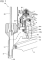
- FIG. 1 is a main part configuration diagram illustrating an example of a nailing machine according to a first embodiment.
- FIG. 2 is an overall configuration diagram illustrating the example of the nailing machine of the first embodiment.
- a nailing machine 1A includes a driving cylinder 2 that is actuated with compressed air serving as a fluid, which is a power source, to perform a striking operation, and an air chamber 3 in which compressed air supplied from an external air compressor (not illustrated) is stored.
- the driving cylinder 2 is provided in an inner portion of a housing 10 having a shape extending in one direction
- the air chamber 3 is provided in an inner portion of a handle 11 extending from the housing 10 in another direction.
- a blowback chamber 31 is provided around a lower portion of the driving cylinder 2 at the inner portion of the housing 10.
- the driving cylinder 2 which is an example of a driving mechanism, includes a driver 20 drives a nail or the like (not illustrated), and a driving piston 21 provided with the driver 20.
- the driving piston 21 is slidably provided. In the driving cylinder 2, the driving piston 21 is moved by being pushed with compressed air to drive the driver 20.
- the compressed air is supplied to the air chamber 3 from a compressed air source such as an air compressor through an air plug 30 provided at an end portion of the handle 11.
- the blowback chamber 31 is supplied with compressed air to drive and return the driving piston 21 after a driving operation to an initial position.
- the nailing machine 1A includes, at one end portion of the housing 10, a nose 12 into which the driver 20 enters, and a magazine 13 that supplies a nail (not illustrated) to the nose 12.
- the nose 12 extends along a moving direction of the driver 20.
- a side at which the nose 12 is provided is referred to as a lower direction.
- the nailing machine 1A includes a main valve 4 that regulates inflow and outflow of compressed air in the air chamber 3 to cause the driving piston 21 to reciprocate, and a actuating valve 5 that actuates the main valve 4.
- the main valve 4 switches between inflow of compressed air from the air chamber 3 into the driving cylinder 2 and discharge of the compressed air from inside the driving cylinder 2 to an outside, so that the driving piston 21 is caused to reciprocate.
- the actuating valve 5 includes a valve stem 50 that is provided so as to be reciprocally movable, and the valve stem 50 is moved by a predetermined amount to open a flow path 40 to actuate the main valve 4.
- the nailing machine 1A includes a trigger 6 that receives one operation for actuating the actuating valve 5, a contact arm 8 that moves in response to another operation to be pressed against an object to which a nail is hit, and a contact lever 7.
- the contact lever 7 is provided so as to be capable of being actuated by an operation of the trigger 6 having received the one operation and by an operation of the contact arm 8 having received the other operation, and switches between presence and absence of actuation of the actuating valve 5.
- the nailing machine 1A includes a regulating part 9 that regulates movement, a moving speed, or a movement amount of the contact lever 7 for a predetermined period of time, and that switches between presence and absence of actuation of the contact lever 7 depending on the contact arm 8, according to presence or absence of engagement between the contact lever 7 and the contact arm 8 in this example.
- the trigger 6 is provided on one side of the handle 11 which is a side where the nose 12 is provided.
- One end portion side of the trigger 6, which is a side close to the housing 10, is rotatably supported by a shaft 60.
- a side opposite the side supported by the shaft 60, that is, the other end portion side of the trigger 6 which is a side far from the housing 10 is biased by a spring 61 in a direction of moving toward a side where the nose 12 is provided, by a rotation operation using the shaft 60 as a fulcrum.
- a moving range of the trigger 6 by the rotation operation using the shaft 60 as a fulcrum is regulated by bringing the trigger 6 abutting against an abutting portion formed in the housing 10 and the handle 11.
- the contact lever 7 includes, at one end portion thereof, an engaging portion 70 with which the contact arm 8 can engage, and the other end portion thereof is rotatably supported by a shaft 71 on the trigger 6.
- a pushing portion 72 capable of pushing the valve stem 50 of the actuating valve 5 is provided between the engaging portion 70 and the shaft 71.
- a side opposite the side supported by the shaft 71 that is, the one end portion side of the contact lever 7 where the engaging portion 70 is provided, is biased by a spring 73 such as a torsion coil spring in a direction of moving toward a side where the nose 12 is provided, by a rotation operation using the shaft 71 as a fulcrum.
- the contact arm 8 is provided so as to be movable along an extension direction of the nose 12, and includes an abutting portion 80 that abuts against an object at a tip end side of the nose 12.
- the contact arm 8 includes a first pushing portion 81 that actuates the contact lever 7, and a second pushing portion 82 that actuates the regulating part 9.
- the contact arm 8 is biased by a spring 83 in a direction of protruding from the tip end side of the nose 12.
- the trigger 6 In a state where an operation is released, the trigger 6 is biased by the spring 61 to move to an initial position thereof by the rotation operation using the shaft 60 as a fulcrum. The trigger 6 is moved, by the rotation operation using the shaft 60 as a fulcrum according to a pulling operation, from the initial position to an operating position thereof where the actuating valve 5 can be actuated by the contact lever 7.
- the contact lever 7 When pushed by the contact arm 8, the contact lever 7 is moved, by the rotation operation using the shaft 71 as a fulcrum, from an initial position thereof to a position where the driving cylinder 2 can be actuated in accordance with the position of the trigger 6, that is, to an actuation possible position in this example where the valve stem 50 can be pushed to actuate the actuating valve 5.
- the contact arm 8 moves from an initial position thereof to an actuating position thereof where the contact lever 7 is actuated by the first pushing portion 81 and the regulating part 9 is actuated by the second pushing portion 82.
- the contact lever 7 When the first pushing portion 81 engages with the engaging portion 70 of the contact lever 7 by an operation of moving the contact arm 8 from the initial position thereof to the actuating position thereof, the contact lever 7 is actuated by the operation of the contact arm 8, and the contact lever 7 is moved from the initial position thereof to the actuation possible position thereof.
- the presence or absence of engagement between the engaging portion 70 of the contact lever 7 and the first pushing portion 81 of the contact arm 8 is switched in accordance with the position of the trigger 6 and the position of the contact lever 7.
- the contact lever 7 moves together with the trigger 6 by the rotation operation of the trigger 6 using the shaft 60 as a fulcrum. Accordingly, the initial position and the actuation possible position of the contact lever 7 are relative positions that change in accordance with the position of the trigger 6, and the positions of the engaging portion 70 and the pushing portion 72 of the contact lever 7 vary depending on whether the trigger 6 is in the initial position thereof or the operating position thereof.
- the pushing portion 72 of the contact lever 7 does not contact the valve stem 50 of the actuating valve 5.
- the pushing portion 72 of the contact lever 7 does not contact the valve stem 50 of the actuating valve 5 even if the trigger 6 moves to the operating position thereof.
- the contact arm 8 moves to the actuating position thereof in a state where the trigger 6 is moved to the initial position thereof, the first pushing portion 81 of the contact arm 8 engages with the engaging portion 70 of the contact lever 7, and the contact lever 7 moves to the actuation possible position thereof. Accordingly, when the trigger 6 moves to the operating position thereof, the pushing portion 72 of the contact lever 7 can push the valve stem 50 of the actuating valve 5, and the actuating valve 5 can be actuated by the contact lever 7.
- the first pushing portion 81 cannot engage with the engaging portion 70 of the contact lever 7 even if the contact arm 8 moves, and the pushing portion 72 of the contact lever 7 cannot push the valve stem 50 of the actuating valve 5 even if the trigger 6 moves to the operating position thereof.
- the actuating valve 5 cannot be actuated, and continuous driving by an operation of pushing the contact arm 8 against an object cannot be performed.
- the regulating part 9 is provided, when the contact arm 8 is operated first and the trigger 6 is operated next, the continuous driving can be performed with the presence or absence of the operation of the contact arm 8 for a predetermined period of time.
- the regulating part 9 includes a regulating member 90 that regulates a position of the contact lever 7 to an actuation standby position where the contact lever 7 can be actuated by the contact arm 8.
- the regulating part 9 includes an oil damper 91 that maintains a state for a predetermined period of time where the contact lever 7 is in the actuation standby position.
- the actuation standby position of the contact lever 7 is a position or a range where the contact lever 7 can engage with the contact arm 8, and the contact lever 7 can be actuated by the contact arm 8 while the contact lever 7 is in this position or range.
- the actuation standby position is referred to as an engagement possible position.
- the regulating member 90 is provided so as to be movable along a moving direction of the contact arm 8, and includes, at one end portion along the moving direction, a pushing portion 90a that pushes the contact lever 7.
- the regulating member 90 is provided with the pushing portion 90a thereof adjacent to the first pushing portion 81 of the contact arm 8.
- the regulating member 90 includes an engaged portion 90b that can engage with the oil damper 91.
- the regulating member 90 is biased by a spring 90c in a direction in which the pushing portion 90a approaches the contact lever 7.
- the regulating member 90 moves from an initial position thereof where the pushing portion 90a does not contact the contact lever 7 to a return regulating position for regulating the position of the contact lever 7 to an engagement possible position where the contact lever 7 and the contact arm 8 can engage with each other.
- the return regulating position of the regulating member 90 is a position where, by an operation of that the regulating member 90 moves by being pushed by the spring 90c, the pushing portion 90a protrudes relative to the first pushing portion 81 and the pushing portion 90a can contact the engaging portion 70 of the contact lever 7 in a state where the contact arm 8 is moved to the initial position thereof.
- the oil damper 91 includes a moving member 92 that moves the regulating member 90, and controls movement, a moving speed, or a movement amount of the moving member 92.
- the oil damper 91 controls the moving speed of the moving member 92.
- the moving member 92 is provided so as to be movable along a moving direction of the regulating member 90, and includes a pushed portion 92a that is pushed by the second pushing portion 82 of the contact arm 8 and an engaging portion 92b that engages with the engaged portion 90b of the regulating member 90.
- the oil damper 91 is provided with the pushed portion 92a of the moving member 92 in a moving path of the second pushing portion 82 of the contact arm 8 that moves from the initial position thereof to the actuating position thereof.
- the moving member 92 moves from an initial position thereof where the regulating member 90 is moved to the initial position thereof, to a clocking starting position for starting measuring a time period during which the movement of the contact lever 7 moved to the engagement possible position thereof after an operation of the contact arm 8 is released is regulated, that is, a time period until the regulating member 90, which is moved to the return regulating position, moving to the initial position thereof in this example.
- the regulating member 90 is provided with the engaged portion 90b in a moving path of the engaging portion 92b which is formed due to the movement of the moving member 92.
- the engaging portion 92b of the moving member 92 and the engaged portion 90b of the regulating member 90 engage with each other. Accordingly, the regulating member 90 moves from the return regulating position thereof to the initial position thereof.
- FIG. 3 is a cross-sectional view of the oil damper according to the first embodiment.
- the oil damper 91 of the first embodiment includes a cylinder tube portion 93a that is filled with oil, a piston 93b that is provided so as to be movable in an inner portion of the cylinder tube portion 93a and whose moving speed is controlled with resistance due to viscosity or the like of oil, and a piston shaft portion 93c that transmits movement of the piston 93b to the moving member 92.
- the cylinder tube portion 93a is provided with a space that is defined in a substantially cylindrical shape and that is filled with oil.
- the piston 93b has a circular shape conforming to a shape of an inner circumferential surface of the cylinder tube portion 93a, and a hole portion 93d through which the oil passes is provided so as to penetrate both sides of the piston 93b.
- a plurality of hole portions 93d are provided along a circumferential direction of the piston 93b.
- One end portion of the piston shaft portion 93c is attached to the piston 93b, and the other end portion thereof protruding from the cylinder tube portion 93a is coupled to the moving member 92.
- the oil damper 91 includes a check valve 93e that switches a load in accordance with a direction, in which the piston 93b moves, by opening and closing the hole portions 93d in accordance with the direction in which the piston 93b moves.
- the check valve 93e is provided on one surface of the piston 93b which is a side where the piston shaft portion 93c protrudes in the piston 93b, and has a shape capable of blocking the hole portions 93d.
- the check valve 93e is movable in a direction of separating from the piston 93b along the moving direction of the piston 93b, and is biased by a valve opening and closing spring 93f in a direction to be pushed against the piston 93b.
- the oil damper 91 includes a spring 93g that expands and contracts in accordance with a position of the piston 93b and that applies a force corresponding to an expansion and contraction amount to the piston 93b.
- the spring 93g is an example of a biasing member, is configured with a coil spring, and is provided between a spring retainer 93h provided in the inner portion of the cylinder tube portion 93a and the other surface of the piston 93b.
- the spring 93g In a state where the moving member 92 is moved to the initial position thereof, the spring 93g is compressed by a predetermined amount and biases the piston 93b in a direction in which the piston shaft portion 93c protrudes from the cylinder tube portion 93a.
- the direction in which the piston shaft portion 93c protrudes from the cylinder tube portion 93a is a direction in which the moving member 92 moves from the clocking starting position thereof toward the initial position thereof.
- the spring 93g is compressed between the spring retainer 93h and the piston 93b. With a force to extend of the compressed spring 93g, the piston 93b is pushed in the direction in which the moving member 92 moves from the clocking starting position thereof toward the initial position thereof.
- the oil damper 91 includes a first bypass flow path 93ii and a second bypass flow path 93i 2 that reduce the load at the time the piston 93b moves.
- the first bypass flow path 93ii is an example of a flow path expanded portion, and is provided to face a position of the piston 93b that is in a state where the moving member 92 is moved to the vicinity of the initial position thereof, which is a terminal position of a movement range of the piston 93b that is moved by a force applied by the spring 93g.
- the first bypass flow path 93ii is formed by providing a recess on the inner circumferential surface of the cylinder tube portion 93a. In the cylinder tube portion 93a, an inner diameter thereof at a portion where the first bypass flow path 93ii is provided is larger than an inner diameter thereof at a portion where the first bypass flow path 93ii is not provided.
- a gap between an outer circumferential surface of the piston 93b and the inner circumferential surface of the cylinder tube portion 93a is increased, as compared with a case where the piston 93b faces the inner circumferential surface of the cylinder tube portion 93a at a portion where the first bypass flow path 93ii is not provided.
- the second bypass flow path 93i 2 is an example of a flow path expanded portion, and is provided to face a position of the piston 93b that is in a state where the moving member 92 is moved to the vicinity of the clocking starting position thereof.
- the second bypass flow path 93i 2 is formed by providing a recess on the inner circumferential surface of the cylinder tube portion 93a. In the cylinder tube portion 93a, an inner diameter thereof at a portion where the second bypass flow path 93i 2 is provided is larger than an inner diameter thereof at a portion where the second bypass flow path 93i 2 is not provided.
- a gap between an outer circumferential surface of the piston 93b and the inner circumferential surface of the cylinder tube portion 93a is widened, as compared with a case where the piston 93b faces the inner circumferential surface of the cylinder tube portion 93a at a portion where the second bypass flow path 93i 2 is not provided.
- the oil damper 91 includes a diaphragm 93j that keeps a volume in the cylinder tube portion 93a substantially constant regardless of the position of the piston 93b.
- the diaphragm 93j is configured with an elastically deformable member and is provided on the other end portion side of the cylinder tube portion 93a.
- the moving member 92 moves from the clocking starting position thereof to the initial position thereof by the force to extend of the spring 93g, and the moving speed of the moving member 92 is controlled with the load applied when the piston 93b moves in the cylinder tube portion 93a due to the viscosity of the oil.
- a time period during which the moving member 92 moves from the clocking starting position thereof to the initial position thereof is controlled, and a time period during which the regulating member 90 moves from the return regulating position thereof to the initial position thereof is controlled. Therefore, with respect to the contact lever 7 having moved to the engagement possible position thereof by an operation of moving the contact arm 8 toward the initial position thereof, a time period until returning to the initial position thereof is controlled by operations of the regulating member 90 and the moving member 92.
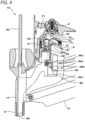
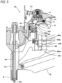
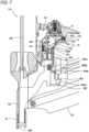
- FIGS. 4 to 9 are illustrative diagrams illustrating examples of operations of the nailing machine according to the first embodiment
- FIGS. 10 to 14 are illustrative diagrams illustrating examples of operations of the oil damper according to the first embodiment.
- the operations of the nailing machine 1A according to the first embodiment will be described below with reference to the drawings.
- the trigger 6 is not pulled and is in the initial position thereof, and the contact arm 8 is not pressed against the object and is in the initial position thereof. Therefore, the contact lever 7, the regulating member 90, and the moving member 92 are also in respective initial positions.
- the engaging portion 70 of the contact lever 7 is positioned in a moving path of the first pushing portion 81 of the contact arm 8.
- the contact arm 8 moves from the initial position thereof to the actuating position thereof by being pressed against the object, starting from the initial state illustrated in FIG. 1 , the first pushing portion 81 of the contact arm 8 pushes the engaging portion 70 of the contact lever 7 as illustrated in FIG. 4 . Accordingly, by the rotation operation using the shaft 71 as a fulcrum, the contact lever 7 moves from the initial position thereof to the actuation possible position thereof where the valve stem 50 of the actuating valve 5 can be pushed to actuate the actuating valve 5. Not that even if the contact lever 7 moves to the actuation possible position thereof, the valve stem 50 cannot be pushed by the contact lever 7 unless the trigger 6 moves to the operating position thereof.
- the second pushing portion 82 of the contact arm 8 pushes the pushed portion 92a of the moving member 92 of the oil damper 91. Accordingly, the moving member 92 of the oil damper 91 moves from the initial position thereof to the clocking starting position thereof.
- the piston 93b faces the first bypass flow path 93ii in the oil damper 91, as illustrated in FIG. 10 . Accordingly, while the moving member 92 is positioned in the vicinity of the initial position thereof in the operation of moving the piston 93b in the direction in which the moving member 92 moves from the initial position thereof toward the clocking starting position thereof as indicated by an arrow U, the resistance at the time the oil flows as indicated by an arrow O 1 between the outer circumferential surface of the piston 93b and the inner circumferential surface of the cylinder tube portion 93a is reduced and the load applied when the piston 93b moves is reduced.
- the check valve 93e is pushed by the oil passing through the hole portions 93d, so that the check valve 93e is separated from the one surface of the piston 93b while compressing the valve opening and closing spring 93f and the hole portions 93d are opened.
- the piston 93b faces the second bypass flow path 93i 2 as illustrated in FIG. 12 . Accordingly, in the operation of moving the piston 93b in the direction in which the moving member 92 moves from the initial position thereof to the clocking starting position thereof, the resistance at the time the oil flows between the outer circumferential surface of the piston 93b and the inner circumferential surface of the cylinder tube portion 93a is reduced and the load applied when the piston 93b moves is reduced.
- the main valve 4 is controlled to actuate the driving cylinder 2 with compressed air, the driving piston 21 moves in a direction in which a fastener (not illustrated), which is a nail in this example, is driven, and a driving operation of the nail (not illustrated) is performed with the driver 20.
- a part of the air in the driving cylinder 2 is supplied to the blowback chamber 31. After the driving operation, the compressed air is supplied from the blowback chamber 31 to the driving cylinder 2, and the driving piston 21 moves in a direction in which the driver 20 is returned.
- the contact arm 8 moves from the actuating position thereof to the initial position thereof by the force of the spring 83 as illustrated in FIG. 6 , by releasing a force of pressing the contact arm 8.
- the regulating member 90 that is moved to the return regulating position regulates the movement of the contact lever 7 that moves in the direction of returning from the actuation possible position thereof toward the initial position thereof, with the pushing portion 90a positioned on a movement path of the contact lever 7.
- the contact lever 7 moves to come into contact with the pushing portion 90a of the regulating member 90 and stops at the engagement possible position thereof. Further, the contact lever 7 having moved to the engagement possible position thereof has the engaging portion 70 thereof positioned on a movement path of the first pushing portion 81 of the contact arm 8.
- the moving member 92 moves from the clocking starting position thereof toward the initial position thereof by the force of the spring 93g, but the moving speed of the moving member 92 is controlled by the oil damper 91. Accordingly, the time period during which the moving member 92 moves from the clocking starting position thereof toward the initial position thereof is controlled, and while the engaging portion 92b of the moving member 92 and the engaged portion 90b of the regulating member 90 are in an unengaged state, the regulating member 90 stops at the return regulating position thereof as illustrated in FIG. 7 .
- the engaging portion 70 is positioned on the movement path of the first pushing portion 81 of the contact arm 8 during a predetermined period of time in which the moving member 92 moves from the clocking starting position thereof to the initial position thereof, that is, during a period of time in which the engaging portion 92b of the moving member 92 and the engaged portion 90b of the regulating member 90 are in an unengaged state.
- the first pushing portion 81 of the contact arm 8 can push the engaging portion 70 of the contact lever 7.
- a continuous driving operation can be performed by an operation of pressing the contact arm 8 against the object during the predetermined period time, with the trigger 6 being in the operating position thereof and in a pulled state.
- the piston 93b faces the first bypass flow path 93ii as illustrated in FIG. 14 . Accordingly, as indicated by the arrow D, in the operation of moving the piston 93b in the direction in which the moving member 92 moves from the clocking starting position thereof toward the initial position thereof, the resistance at the time the oil flows as indicated by an arrow O 3 between the outer circumferential surface of the piston 93b and the inner circumferential surface of the cylinder tube portion 93a is reduced and the load applied when the piston 93b moves is reduced.
- the contact lever 7 moves from the engagement possible position to the initial position thereof, by the rotation operation using the shaft 71 as a fulcrum by the spring 73, in a case where the trigger 6 is in the operating position thereof.
- the engaging portion 70 of the contact lever 7 is retracted from the moving path of the first pushing portion 81 of the contact arm 8.
- the first pushing portion 81 of the contact arm 8 does not contact the engaging portion 70 of the contact lever 7 and the contact lever 7 is not pushed, as illustrated in FIG. 9 .
- the actuating valve 5 is not pushed by the contact lever 7, and the driving operation is not performed. Therefore, the continuous driving operation by pressing the contact arm 8 against the object, with the trigger 6 being in the operating position thereof and in a pulled state, can be regulated by lapse of time using a mechanical configuration.
- the contact lever 7 moves to the initial position thereof.
- the contact arm 8 is moved to the initial position thereof by releasing the force of pressing the contact arm 8.
- the trigger 6 moves to the initial position thereof by releasing the force of pulling the trigger 6. Accordingly, the initial state as illustrated in FIG. 1 is recovered. In the initial state, the engaging portion 70 of the contact lever 7 moves to the moving path of the first pushing portion 81 of the contact arm 8.
- the first pushing portion 81 of the contact arm 8 does not contact the engaging portion 70 of the contact lever 7 and the contact lever 7 is not pushed, even when the contact arm 8 moves to the actuating position thereof by the operation of being pressed against the object.
- valve stem 50 of the actuating valve 5 is not pushed by the contact lever 7, and the driving operation is not performed. Therefore, it is possible to regulate a driving operation that is by an operation other than an operation of a normal procedure of pressing the contact arm 8 against the object before pulling the trigger 6.
- the oil damper 91 is provided to reduce the moving speed of the moving member 92 in the operation of moving from the clocking starting position thereof to the initial position thereof, and provides the load applied when the piston 93b moves with the viscosity of the oil.
- the viscosity of the oil acts as a load applied when the piston 93b moves, and the operating load of the contact arm 8 increases.
- the oil damper 91 is provided with the check valve 93e on the piston 93b.
- the hole portions 93d of the piston 93b are opened when the piston 93b moves in a direction in the operation of pressing the contact arm 8 against the object, thereby reducing the load applied when the piston 93b moves. Accordingly, the operating load of the contact arm 8 is reduced.
- the hole portions 93d of the piston 93b are closed by the check valve 93e, so that the load required when the piston 93b moves can be applied.
- the oil damper 91 is provided with the first bypass flow path 93ii, when the moving member 92 moves to the vicinity of the initial position thereof in the operation of moving the piston 93b in the direction in which the moving member 92 moves from the clocking starting position thereof toward the initial position thereof, the resistance at the time the oil flows between the outer circumferential surface of the piston 93b and the inner circumferential surface of the cylinder tube portion 93a is reduced and the load applied when the piston 93b moves is reduced.
- the moving member 92 can be reliably moved to the initial position thereof during the predetermined period of time by the force to extend of the spring 93g since the load applied when the piston 93b moves is reduced. Therefore, it is possible to reliably control a period of time, during which the continuous driving operation can be performed, by the operation of pressing the contact arm 8 against the object with the trigger 6 being in the operating position thereof and in a pulled state.
- the resistance of the oil at the time the piston 93b moves can be reduced, and a configuration can be easily implemented in which the resistance of the oil at the time the piston 93b moves is changed in accordance with a change in the force applied to the piston 93b by the spring 93g.
- the oil damper 91 is provided with the second bypass flow path 93i 2 , when the moving member 92 moves to the vicinity of the clocking starting position thereof in the operation of moving the piston 93b in the direction in which the moving member 92 moves from the initial position thereof toward the clocking starting position thereof, the resistance at the time the oil flows between the outer circumferential surface of the piston 93b and the inner circumferential surface of the cylinder tube portion 93a is reduced and the load applied when the piston 93b moves is reduced.
- the second bypass flow path 93i 2 may not be provided.
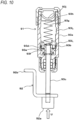
- FIG. 15 is a cross-sectional view illustrating an oil damper according to a second embodiment.
- the oil damper 91 of the second embodiment includes a cylinder tube portion 93k that is filled with oil, the piston 93b that is provided so as to be movable in an inner portion of the cylinder tube portion 93k and whose moving speed is controlled with viscosity of the oil, and the piston shaft portion 93c that transmits movement of the piston 93b to the moving member 92.
- the cylinder tube portion 93k is provided with a space that is defined in a substantially cylindrical shape and that is filled with oil.
- the piston 93b has a circular shape conforming to a shape of an inner circumferential surface of the cylinder tube portion 93k, and a plurality of hole portions 93d through which the oil passes are provided so as to penetrate both sides of the piston 93b.
- One end portion of the piston shaft portion 93c is attached to the piston 93b, and the other end portion thereof protruding from the cylinder tube portion 93a is coupled to the moving member 92.
- the oil damper 91 includes the check valve 93e that switches a load in accordance with a direction, in which the piston 93b moves, by opening and closing the hole portions 93d in accordance with the direction in which the piston 93b moves.
- the check valve 93e is movable in a direction of separating from the piston 93b along the moving direction of the piston 93b, and is biased by the valve opening and closing spring 93f in a direction to be pushed against the piston 93b.
- the check valve 93e In an operation of moving the piston 93b in a direction in which the moving member 92 moves from an initial position thereof to a clocking starting position thereof, the check valve 93e is pushed by the oil passing through the hole portions 93d, so that the check valve 93e is separated from one surface of the piston 93b while compressing the valve opening and closing spring 93f and the hole portions 93d are opened.
- the oil damper 91 includes the spring 93g that presses the piston 93b.
- the spring 93g is an example of a biasing member, is configured with a coil spring, and is provided between the spring retainer 93h provided in the inner portion of the cylinder tube portion 93k and the other surface of the piston 93b.
- the oil damper 91 includes a bypass flow path 93m that reduces a load applied when the piston 93b moves.
- the bypass flow path 93m is an example of a flow path expanded portion, and is provided to face a position of the piston 93b that is in a state where the moving member 92 is moved to the vicinity of the initial position thereof, which is a terminal position of a movement range of the piston 93b that is moved by a force applied by the spring 93g.
- the inner circumferential surface of the cylinder tube portion 93k is in a tapered shape such that an inner diameter gradually increases toward a portion facing the piston 93b in a state where the moving member 92 is moved to the vicinity of the initial position thereof, and an inner diameter of a portion where the bypass flow path 93m is provided is larger than an inner diameter of a portion where the bypass flow path 93m is not provided.
- the oil damper 91 includes a diaphragm 93j that keeps a volume in the cylinder tube portion 93k substantially constant regardless of the position of the piston 93b.
- the diaphragm 93j is configured with an elastically deformable member and is provided on the other end portion side of the cylinder tube portion 93k.
- the moving member 92 moves from the clocking starting position thereof to the initial position thereof by a force to extend of the spring 93g, and a moving speed of the moving member 92 is controlled with the load applied when the piston 93b moves in the cylinder tube portion 93k due to the viscosity of the oil.
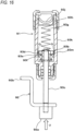
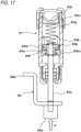
- FIGS. 16 to 20 are illustrative diagrams illustrating examples of operations of the oil damper according to the second embodiment, and among operations of the nailing machine 1A, the operations of the oil damper according to the second embodiment will be described.
- the piston 93b faces the bypass flow path 93m in the oil damper 91 as illustrated in FIG. 16 . Accordingly, while the moving member 92 is positioned in the vicinity of the initial position thereof in the operation of moving the piston 93b in the direction in which the moving member 92 moves from the initial position thereof toward the clocking starting position thereof as indicated by an arrow U, the resistance at the time the oil flows as indicated by an arrow O 1 between the outer circumferential surface of the piston 93b and the inner circumferential surface of the cylinder tube portion 93k is reduced and the load applied when the piston 93b moves is reduced.
- the check valve 93e is pushed by the oil passing through the hole portions 93d, so that the check valve 93e is separated from the one surface of the piston 93b while compressing the valve opening and closing spring 93f and the hole portions 93d are opened.
- oil dampers using the resistance due to the viscosity of oil are described as examples of the fluid damper of the present invention, and the present invention is not limited thereto.
- the present invention is applicable to various types of cylinder dampers, for example, a damper obtained by filling and enclosing a liquid different from oil in a cylinder, a damper obtained by filling and enclosing a gas such as nitrogen gas in a cylinder instead of oil, or a damper having a configuration of controlling inflow of gas into a cylinder and outflow of the gas from inside the cylinder.
- a nailing machine that drives a nail is described as an example of the driving tool of the present invention, and the present invention is not limited thereto.
- the present invention is also applicable to, for example, a screw driving machine that drives a screw.
- 1A nailing machine (driving tool); 10 housing; 11 handle; 12 nose; 13 magazine; 2 driving cylinder (driving mechanism); 20 driver; 21 driving piston; 3 air chamber; 30 air plug; 31 blowback chamber; 4 main valve; 5 actuating valve; 50 valve stem; 6 trigger; 60 shaft; 61 spring; 7 contact lever; 70 engaging portion; 71 shaft; 72 pushing portion; 73 spring; 8 contact arm; 80 abutting portion; 81 first pushing portion; 82 second pushing portion; 83 spring; 9 regulating part; 90 regulating member; 90a pushing portion; 90b engaged portion; 90c spring; 91 oil damper; 92 moving member; 92a pushed portion; 92b engaging portion; 93a cylinder tube portion; 93b piston; 93c piston shaft portion; 93d hole portion; 93e check valve; 93f valve opening and closing spring; 93g spring (biasing member); 93h spring retainer; 93ii first bypass flow path (flow path expanded portion); 93i 2 second bypass flow path (flow
Landscapes
- Engineering & Computer Science (AREA)
- Mechanical Engineering (AREA)
- Physics & Mathematics (AREA)
- Fluid Mechanics (AREA)
- General Engineering & Computer Science (AREA)
- Portable Nailing Machines And Staplers (AREA)
- Fluid-Damping Devices (AREA)
Claims (6)
- Outil d'entraînement comprenant :un mécanisme d'entraînement (2) qui entraîne un élément de fixation distribué dans une partie de nez ;une gâchette (6) qui reçoit une opération pour actionner le mécanisme d'entraînement (2) ;un bras de contact (8) qui est prévu de manière à pouvoir se déplacer en va-et-vient et qui reçoit une autre opération pour actionner le mécanisme d'entraînement (2) ;un levier de contact (7) qui est prévu de manière à pouvoir être actionné par des opérations de la gâchette et du bras de contact (8) et qui est configuré pour commuter entre la présence et l'absence d'actionnement du mécanisme d'entraînement (2) ;caractérisé en ce queun amortisseur à fluide qui est configuré pour commander une vitesse de déplacement du levier de contact (7), dans lequell'amortisseur à fluide comprend :une partie de tube cylindrique (93a, 93k) qui est remplie d'un fluide ;un piston (93b) qui est prévu de manière à pouvoir se déplacer dans une partie intérieure de la partie de tube cylindrique (93a, 93k) et dont la vitesse de déplacement est commandée par la résistance du fluide ; etun élément de sollicitation (93g) qui se dilate et se contracte conformément à une position du piston (93b) et qui applique une force correspondant à une quantité de dilatation et de contraction de l'élément de sollicitation (93g) au piston (93b), dans lequella résistance du fluide au moment où le piston (93b) se déplace est changée conformément à la position du piston (93b).
- Outil d'entraînement selon la revendication 1, dans lequel
la résistance du fluide au moment où le piston (93b) se déplace est changée conformément à un changement de la force appliquée au piston (93b) par l'élément de sollicitation (93g). - Outil d'entraînement selon la revendication 2, dans lequel
la force appliquée au piston (93b) par l'élément de sollicitation (93g) change conformément à la quantité de dilatation et de contraction de l'élément de sollicitation (93g), et lorsque le piston (93b) se déplace d'une position où la force appliquée à celui-ci par l'élément de sollicitation (93g) est importante jusqu'à une position où la force appliquée à celui-ci par l'élément de sollicitation (93g) est faible, la résistance du fluide au moment où le piston (93b) se déplace est réduite. - Outil d'entraînement selon l'une quelconque des revendications 1 à 3, dans lequel
la résistance du fluide au moment où le piston (93b) se déplace est changée en changeant la surface d'un trajet d'écoulement à travers lequel passe le fluide. - Outil d'entraînement selon l'une quelconque des revendications 1 à 4, l'amortisseur à fluide comprenant en outre :
une partie dilatée de trajet d'écoulement où une surface d'un trajet d'écoulement à travers lequel passe le fluide est augmentée conformément à une position terminale d'une plage de déplacement du piston (93b) qui est déplacé par la force appliquée par l'élément de sollicitation (93g). - Outil d'entraînement selon la revendication 1 comprenant en outre :une partie de régulation (9) qui est configurée pour commuter entre la présence et l'absence d'actionnement du bras de contact (8) du levier de contact (7), dans lequella partie de régulation (9) comporte :un élément de régulation (90) qui est configuré pour réguler une position du levier de contact (7) à une position d'attente d'actionnement où le bras de contact (8) est capable d'actionner le levier de contact (7) ; etl'amortisseur à fluide, etl'amortisseur à fluide est configuré pour commander une vitesse de déplacement d'un élément mobile qui actionne l'élément de régulation.
Applications Claiming Priority (2)
| Application Number | Priority Date | Filing Date | Title |
|---|---|---|---|
| JP2018036896 | 2018-03-01 | ||
| PCT/JP2019/007712 WO2019168075A1 (fr) | 2018-03-01 | 2019-02-27 | Amortisseur à huile et outil d'entraînement |
Publications (4)
| Publication Number | Publication Date |
|---|---|
| EP3760894A1 EP3760894A1 (fr) | 2021-01-06 |
| EP3760894A4 EP3760894A4 (fr) | 2021-12-08 |
| EP3760894C0 EP3760894C0 (fr) | 2024-11-06 |
| EP3760894B1 true EP3760894B1 (fr) | 2024-11-06 |
Family
ID=67805365
Family Applications (1)
| Application Number | Title | Priority Date | Filing Date |
|---|---|---|---|
| EP19760964.7A Active EP3760894B1 (fr) | 2018-03-01 | 2019-02-27 | Amortisseur à huile et outil d'entraînement |
Country Status (4)
| Country | Link |
|---|---|
| US (1) | US11590639B2 (fr) |
| EP (1) | EP3760894B1 (fr) |
| JP (1) | JP7222389B2 (fr) |
| WO (1) | WO2019168075A1 (fr) |
Families Citing this family (7)
| Publication number | Priority date | Publication date | Assignee | Title |
|---|---|---|---|---|
| WO2023158729A1 (fr) | 2022-02-18 | 2023-08-24 | Milwaukee Electric Tool Corporation | Visseuse de fermeture motorisée |
| US12533778B2 (en) | 2022-03-04 | 2026-01-27 | Milwaukee Electric Tool Corporation | Powered fastener driver |
| DE112023000450T5 (de) | 2022-03-04 | 2024-10-24 | Milwaukee Electric Tool Corporation | Fremdkraftbetätigter befestigungsmitteleintreiber |
| US12434367B2 (en) | 2022-03-04 | 2025-10-07 | Milwaukee Electric Tool Corporation | Powered fastener driver |
| US12337451B2 (en) * | 2022-08-15 | 2025-06-24 | Taizhou Dajiang Ind. Co. Ltd. | Energy storage and driving mechanisms and nail gun having same |
| DE102024112221A1 (de) | 2023-05-05 | 2024-11-07 | Milwaukee Electric Tool Corporation | Fremdkraftbetätigter befestigungsmitteleintreiber |
| DE102024112566A1 (de) | 2023-05-05 | 2024-11-07 | Milwaukee Electric Tool Corporation | Fremdkraftbetätigter befestigungsmitteleintreiber |
Family Cites Families (13)
| Publication number | Priority date | Publication date | Assignee | Title |
|---|---|---|---|---|
| US3803840A (en) | 1972-12-22 | 1974-04-16 | Illinois Tool Works | Power driver device |
| JPS55175647U (fr) * | 1979-06-05 | 1980-12-16 | ||
| JPS57164335U (fr) * | 1981-04-13 | 1982-10-16 | ||
| DE3142237A1 (de) * | 1981-10-24 | 1983-05-05 | Signode Corp., Glenview, Ill. | Pneumatisch betaetigbares befestigungsmitteleintreibgeraet |
| JP3287172B2 (ja) * | 1995-04-05 | 2002-05-27 | マックス株式会社 | 釘打ち機のトリガ装置 |
| JP3344458B2 (ja) * | 1996-11-28 | 2002-11-11 | マックス株式会社 | 釘打機の連続打ちと単発打ちの作動タイミング調整機構 |
| DE202009006233U1 (de) | 2009-04-30 | 2010-09-23 | Lautenschläger, Horst | Dämpferzylinder für eine Dämpfungseinrichtung für Möbel |
| JP5338841B2 (ja) * | 2011-04-01 | 2013-11-13 | Smc株式会社 | 油圧式ショックアブソーバ |
| GB2513848A (en) * | 2013-05-03 | 2014-11-12 | Lama D D Dekani | Improvements in damper assemblies |
| JP6408944B2 (ja) | 2015-03-24 | 2018-10-17 | 株式会社マキタ | 打ち込み工具 |
| JP6562086B2 (ja) * | 2015-12-28 | 2019-08-21 | 工機ホールディングス株式会社 | 打込機 |
| JP2018036896A (ja) | 2016-08-31 | 2018-03-08 | 株式会社ジャパンディスプレイ | タッチセンサ及び表示装置 |
| JP6824781B2 (ja) * | 2017-03-01 | 2021-02-03 | 株式会社マキタ | 打ち込み工具 |
-
2019
- 2019-02-27 WO PCT/JP2019/007712 patent/WO2019168075A1/fr not_active Ceased
- 2019-02-27 JP JP2020503597A patent/JP7222389B2/ja active Active
- 2019-02-27 EP EP19760964.7A patent/EP3760894B1/fr active Active
- 2019-02-27 US US16/975,348 patent/US11590639B2/en active Active
Also Published As
| Publication number | Publication date |
|---|---|
| JPWO2019168075A1 (ja) | 2021-03-04 |
| US20200391365A1 (en) | 2020-12-17 |
| JP7222389B2 (ja) | 2023-02-15 |
| EP3760894C0 (fr) | 2024-11-06 |
| EP3760894A4 (fr) | 2021-12-08 |
| WO2019168075A1 (fr) | 2019-09-06 |
| US11590639B2 (en) | 2023-02-28 |
| EP3760894A1 (fr) | 2021-01-06 |
Similar Documents
| Publication | Publication Date | Title |
|---|---|---|
| EP3760894B1 (fr) | Amortisseur à huile et outil d'entraînement | |
| EP3760895A1 (fr) | Amortisseur à fluide et outil d'entraînement | |
| EP3760382B1 (fr) | Outil d'entrainement d'élément de fixation | |
| JP6950423B2 (ja) | 打込み工具 | |
| EP3398722A1 (fr) | Dispositif d'entraînement | |
| JP7043771B2 (ja) | 打込み工具 | |
| JP7392765B2 (ja) | 空気圧工具 | |
| CN111225769A (zh) | 具有安全调节元件的气动钉枪 | |
| US11707825B2 (en) | Pneumatic tool | |
| US10898993B2 (en) | Driving tool | |
| RU2699883C1 (ru) | Пневматический гвоздезабивной пистолет с однократным и контактным запуском | |
| US20230278178A1 (en) | Pneumatic tool | |
| US11780067B2 (en) | Pneumatic tool |
Legal Events
| Date | Code | Title | Description |
|---|---|---|---|
| STAA | Information on the status of an ep patent application or granted ep patent |
Free format text: STATUS: THE INTERNATIONAL PUBLICATION HAS BEEN MADE |
|
| PUAI | Public reference made under article 153(3) epc to a published international application that has entered the european phase |
Free format text: ORIGINAL CODE: 0009012 |
|
| STAA | Information on the status of an ep patent application or granted ep patent |
Free format text: STATUS: REQUEST FOR EXAMINATION WAS MADE |
|
| 17P | Request for examination filed |
Effective date: 20200824 |
|
| AK | Designated contracting states |
Kind code of ref document: A1 Designated state(s): AL AT BE BG CH CY CZ DE DK EE ES FI FR GB GR HR HU IE IS IT LI LT LU LV MC MK MT NL NO PL PT RO RS SE SI SK SM TR |
|
| AX | Request for extension of the european patent |
Extension state: BA ME |
|
| DAV | Request for validation of the european patent (deleted) | ||
| DAX | Request for extension of the european patent (deleted) | ||
| A4 | Supplementary search report drawn up and despatched |
Effective date: 20211110 |
|
| RIC1 | Information provided on ipc code assigned before grant |
Ipc: F16F 9/19 20060101ALN20211104BHEP Ipc: B25C 1/04 20060101ALI20211104BHEP Ipc: B25C 1/00 20060101ALI20211104BHEP Ipc: F16F 9/32 20060101ALI20211104BHEP Ipc: F16F 9/48 20060101AFI20211104BHEP |
|
| RIC1 | Information provided on ipc code assigned before grant |
Ipc: F16F 9/19 20060101ALN20240328BHEP Ipc: B25C 1/04 20060101ALI20240328BHEP Ipc: B25C 1/00 20060101ALI20240328BHEP Ipc: F16F 9/32 20060101ALI20240328BHEP Ipc: F16F 9/48 20060101AFI20240328BHEP |
|
| GRAP | Despatch of communication of intention to grant a patent |
Free format text: ORIGINAL CODE: EPIDOSNIGR1 |
|
| STAA | Information on the status of an ep patent application or granted ep patent |
Free format text: STATUS: GRANT OF PATENT IS INTENDED |
|
| INTG | Intention to grant announced |
Effective date: 20240604 |
|
| GRAS | Grant fee paid |
Free format text: ORIGINAL CODE: EPIDOSNIGR3 |
|
| GRAA | (expected) grant |
Free format text: ORIGINAL CODE: 0009210 |
|
| STAA | Information on the status of an ep patent application or granted ep patent |
Free format text: STATUS: THE PATENT HAS BEEN GRANTED |
|
| AK | Designated contracting states |
Kind code of ref document: B1 Designated state(s): AL AT BE BG CH CY CZ DE DK EE ES FI FR GB GR HR HU IE IS IT LI LT LU LV MC MK MT NL NO PL PT RO RS SE SI SK SM TR |
|
| REG | Reference to a national code |
Ref country code: GB Ref legal event code: FG4D |
|
| REG | Reference to a national code |
Ref country code: CH Ref legal event code: EP |
|
| REG | Reference to a national code |
Ref country code: DE Ref legal event code: R096 Ref document number: 602019061529 Country of ref document: DE |
|
| REG | Reference to a national code |
Ref country code: IE Ref legal event code: FG4D |
|
| U01 | Request for unitary effect filed |
Effective date: 20241125 |
|
| U07 | Unitary effect registered |
Designated state(s): AT BE BG DE DK EE FI FR IT LT LU LV MT NL PT RO SE SI Effective date: 20241202 |
|
| U20 | Renewal fee for the european patent with unitary effect paid |
Year of fee payment: 7 Effective date: 20250107 |
|
| PG25 | Lapsed in a contracting state [announced via postgrant information from national office to epo] |
Ref country code: IS Free format text: LAPSE BECAUSE OF FAILURE TO SUBMIT A TRANSLATION OF THE DESCRIPTION OR TO PAY THE FEE WITHIN THE PRESCRIBED TIME-LIMIT Effective date: 20250306 Ref country code: HR Free format text: LAPSE BECAUSE OF FAILURE TO SUBMIT A TRANSLATION OF THE DESCRIPTION OR TO PAY THE FEE WITHIN THE PRESCRIBED TIME-LIMIT Effective date: 20241106 |
|
| PG25 | Lapsed in a contracting state [announced via postgrant information from national office to epo] |
Ref country code: ES Free format text: LAPSE BECAUSE OF FAILURE TO SUBMIT A TRANSLATION OF THE DESCRIPTION OR TO PAY THE FEE WITHIN THE PRESCRIBED TIME-LIMIT Effective date: 20241106 |
|
| PG25 | Lapsed in a contracting state [announced via postgrant information from national office to epo] |
Ref country code: NO Free format text: LAPSE BECAUSE OF FAILURE TO SUBMIT A TRANSLATION OF THE DESCRIPTION OR TO PAY THE FEE WITHIN THE PRESCRIBED TIME-LIMIT Effective date: 20250206 |
|
| PG25 | Lapsed in a contracting state [announced via postgrant information from national office to epo] |
Ref country code: GR Free format text: LAPSE BECAUSE OF FAILURE TO SUBMIT A TRANSLATION OF THE DESCRIPTION OR TO PAY THE FEE WITHIN THE PRESCRIBED TIME-LIMIT Effective date: 20250207 |
|
| PG25 | Lapsed in a contracting state [announced via postgrant information from national office to epo] |
Ref country code: PL Free format text: LAPSE BECAUSE OF FAILURE TO SUBMIT A TRANSLATION OF THE DESCRIPTION OR TO PAY THE FEE WITHIN THE PRESCRIBED TIME-LIMIT Effective date: 20241106 |
|
| PG25 | Lapsed in a contracting state [announced via postgrant information from national office to epo] |
Ref country code: RS Free format text: LAPSE BECAUSE OF FAILURE TO SUBMIT A TRANSLATION OF THE DESCRIPTION OR TO PAY THE FEE WITHIN THE PRESCRIBED TIME-LIMIT Effective date: 20250206 |
|
| PG25 | Lapsed in a contracting state [announced via postgrant information from national office to epo] |
Ref country code: SM Free format text: LAPSE BECAUSE OF FAILURE TO SUBMIT A TRANSLATION OF THE DESCRIPTION OR TO PAY THE FEE WITHIN THE PRESCRIBED TIME-LIMIT Effective date: 20241106 |
|
| PG25 | Lapsed in a contracting state [announced via postgrant information from national office to epo] |
Ref country code: SK Free format text: LAPSE BECAUSE OF FAILURE TO SUBMIT A TRANSLATION OF THE DESCRIPTION OR TO PAY THE FEE WITHIN THE PRESCRIBED TIME-LIMIT Effective date: 20241106 |
|
| PG25 | Lapsed in a contracting state [announced via postgrant information from national office to epo] |
Ref country code: CZ Free format text: LAPSE BECAUSE OF FAILURE TO SUBMIT A TRANSLATION OF THE DESCRIPTION OR TO PAY THE FEE WITHIN THE PRESCRIBED TIME-LIMIT Effective date: 20241106 |
|
| PLBE | No opposition filed within time limit |
Free format text: ORIGINAL CODE: 0009261 |
|
| STAA | Information on the status of an ep patent application or granted ep patent |
Free format text: STATUS: NO OPPOSITION FILED WITHIN TIME LIMIT |
|
| PG25 | Lapsed in a contracting state [announced via postgrant information from national office to epo] |
Ref country code: MC Free format text: LAPSE BECAUSE OF FAILURE TO SUBMIT A TRANSLATION OF THE DESCRIPTION OR TO PAY THE FEE WITHIN THE PRESCRIBED TIME-LIMIT Effective date: 20241106 |
|
| REG | Reference to a national code |
Ref country code: CH Ref legal event code: PL |
|
| 26N | No opposition filed |
Effective date: 20250807 |
|
| PG25 | Lapsed in a contracting state [announced via postgrant information from national office to epo] |
Ref country code: CH Free format text: LAPSE BECAUSE OF NON-PAYMENT OF DUE FEES Effective date: 20250228 |
|
| PG25 | Lapsed in a contracting state [announced via postgrant information from national office to epo] |
Ref country code: IE Free format text: LAPSE BECAUSE OF NON-PAYMENT OF DUE FEES Effective date: 20250227 |
|
| U20 | Renewal fee for the european patent with unitary effect paid |
Year of fee payment: 8 Effective date: 20260106 |
|
| PGFP | Annual fee paid to national office [announced via postgrant information from national office to epo] |
Ref country code: GB Payment date: 20260106 Year of fee payment: 8 |
|
| U1N | Appointed representative for the unitary patent procedure changed after the registration of the unitary effect |
Representative=s name: MARKS & CLERK LLP; GB |