EP3760914B2 - Personen- und fahrzeugbezogene entblendung von leuchten - Google Patents
Personen- und fahrzeugbezogene entblendung von leuchten Download PDFInfo
- Publication number
- EP3760914B2 EP3760914B2 EP20183768.9A EP20183768A EP3760914B2 EP 3760914 B2 EP3760914 B2 EP 3760914B2 EP 20183768 A EP20183768 A EP 20183768A EP 3760914 B2 EP3760914 B2 EP 3760914B2
- Authority
- EP
- European Patent Office
- Prior art keywords
- luminaire
- sensor
- vehicle
- person
- light
- Prior art date
- Legal status (The legal status is an assumption and is not a legal conclusion. Google has not performed a legal analysis and makes no representation as to the accuracy of the status listed.)
- Active
Links
Images


Classifications
-
- F—MECHANICAL ENGINEERING; LIGHTING; HEATING; WEAPONS; BLASTING
- F21—LIGHTING
- F21V—FUNCTIONAL FEATURES OR DETAILS OF LIGHTING DEVICES OR SYSTEMS THEREOF; STRUCTURAL COMBINATIONS OF LIGHTING DEVICES WITH OTHER ARTICLES, NOT OTHERWISE PROVIDED FOR
- F21V23/00—Arrangement of electric circuit elements in or on lighting devices
- F21V23/04—Arrangement of electric circuit elements in or on lighting devices the elements being switches
- F21V23/0442—Arrangement of electric circuit elements in or on lighting devices the elements being switches activated by means of a sensor, e.g. motion or photodetectors
- F21V23/0471—Arrangement of electric circuit elements in or on lighting devices the elements being switches activated by means of a sensor, e.g. motion or photodetectors the sensor detecting the proximity, the presence or the movement of an object or a person
-
- F—MECHANICAL ENGINEERING; LIGHTING; HEATING; WEAPONS; BLASTING
- F21—LIGHTING
- F21S—NON-PORTABLE LIGHTING DEVICES; SYSTEMS THEREOF; VEHICLE LIGHTING DEVICES SPECIALLY ADAPTED FOR VEHICLE EXTERIORS
- F21S8/00—Lighting devices intended for fixed installation
- F21S8/04—Lighting devices intended for fixed installation intended only for mounting on a ceiling or the like overhead structures
-
- H—ELECTRICITY
- H05—ELECTRIC TECHNIQUES NOT OTHERWISE PROVIDED FOR
- H05B—ELECTRIC HEATING; ELECTRIC LIGHT SOURCES NOT OTHERWISE PROVIDED FOR; CIRCUIT ARRANGEMENTS FOR ELECTRIC LIGHT SOURCES, IN GENERAL
- H05B47/00—Circuit arrangements for operating light sources in general, i.e. where the type of light source is not relevant
- H05B47/10—Controlling the light source
- H05B47/105—Controlling the light source in response to determined parameters
- H05B47/115—Controlling the light source in response to determined parameters by determining the presence or movement of objects or living beings
-
- F—MECHANICAL ENGINEERING; LIGHTING; HEATING; WEAPONS; BLASTING
- F21—LIGHTING
- F21W—INDEXING SCHEME ASSOCIATED WITH SUBCLASSES F21K, F21L, F21S and F21V, RELATING TO USES OR APPLICATIONS OF LIGHTING DEVICES OR SYSTEMS
- F21W2131/00—Use or application of lighting devices or systems not provided for in codes F21W2102/00-F21W2121/00
- F21W2131/10—Outdoor lighting
- F21W2131/103—Outdoor lighting of streets or roads
-
- H—ELECTRICITY
- H05—ELECTRIC TECHNIQUES NOT OTHERWISE PROVIDED FOR
- H05B—ELECTRIC HEATING; ELECTRIC LIGHT SOURCES NOT OTHERWISE PROVIDED FOR; CIRCUIT ARRANGEMENTS FOR ELECTRIC LIGHT SOURCES, IN GENERAL
- H05B47/00—Circuit arrangements for operating light sources in general, i.e. where the type of light source is not relevant
- H05B47/10—Controlling the light source
- H05B47/105—Controlling the light source in response to determined parameters
- H05B47/115—Controlling the light source in response to determined parameters by determining the presence or movement of objects or living beings
- H05B47/12—Controlling the light source in response to determined parameters by determining the presence or movement of objects or living beings by detecting audible sound
-
- H—ELECTRICITY
- H05—ELECTRIC TECHNIQUES NOT OTHERWISE PROVIDED FOR
- H05B—ELECTRIC HEATING; ELECTRIC LIGHT SOURCES NOT OTHERWISE PROVIDED FOR; CIRCUIT ARRANGEMENTS FOR ELECTRIC LIGHT SOURCES, IN GENERAL
- H05B47/00—Circuit arrangements for operating light sources in general, i.e. where the type of light source is not relevant
- H05B47/10—Controlling the light source
- H05B47/105—Controlling the light source in response to determined parameters
- H05B47/115—Controlling the light source in response to determined parameters by determining the presence or movement of objects or living beings
- H05B47/125—Controlling the light source in response to determined parameters by determining the presence or movement of objects or living beings by using cameras
-
- H—ELECTRICITY
- H05—ELECTRIC TECHNIQUES NOT OTHERWISE PROVIDED FOR
- H05B—ELECTRIC HEATING; ELECTRIC LIGHT SOURCES NOT OTHERWISE PROVIDED FOR; CIRCUIT ARRANGEMENTS FOR ELECTRIC LIGHT SOURCES, IN GENERAL
- H05B47/00—Circuit arrangements for operating light sources in general, i.e. where the type of light source is not relevant
- H05B47/10—Controlling the light source
- H05B47/105—Controlling the light source in response to determined parameters
- H05B47/115—Controlling the light source in response to determined parameters by determining the presence or movement of objects or living beings
- H05B47/13—Controlling the light source in response to determined parameters by determining the presence or movement of objects or living beings by using passive infrared detectors
-
- Y—GENERAL TAGGING OF NEW TECHNOLOGICAL DEVELOPMENTS; GENERAL TAGGING OF CROSS-SECTIONAL TECHNOLOGIES SPANNING OVER SEVERAL SECTIONS OF THE IPC; TECHNICAL SUBJECTS COVERED BY FORMER USPC CROSS-REFERENCE ART COLLECTIONS [XRACs] AND DIGESTS
- Y02—TECHNOLOGIES OR APPLICATIONS FOR MITIGATION OR ADAPTATION AGAINST CLIMATE CHANGE
- Y02B—CLIMATE CHANGE MITIGATION TECHNOLOGIES RELATED TO BUILDINGS, e.g. HOUSING, HOUSE APPLIANCES OR RELATED END-USER APPLICATIONS
- Y02B20/00—Energy efficient lighting technologies, e.g. halogen lamps or gas discharge lamps
- Y02B20/40—Control techniques providing energy savings, e.g. smart controller or presence detection
Definitions
- the present invention relates to a luminaire for stationary installation in an indoor area (e.g. high-bay warehouse or corridor) or outdoor area (e.g. traffic route or parking lot) with a variable light distribution.
- an indoor area e.g. high-bay warehouse or corridor
- outdoor area e.g. traffic route or parking lot
- luminaires with a wide light distribution are used in many applications to achieve uniform illumination of a large area with as few luminaires as possible.
- high luminous fluxes must be used and a large proportion of the light emitted by the luminaire must leave the luminaire at very small angles (relative to the horizontal).
- both of these measures increase the glare effect of the luminaire. Therefore, there are regulations for glare limitation (e.g. DIN EN 13201), particularly for activities involving critical visual tasks. To avoid glare for critical visual tasks and still achieve high illuminance at the user level, shorter luminaire spacing must be selected.
- a disadvantage is that, on the one hand, higher installation and acquisition costs are incurred, and on the other hand, a larger number of luminaires must be maintained.
- a luminaire according to the preamble of claim 1 is known from US 2014/320023 A1 Further lighting devices, which are particularly designed to reduce glare, are known from US 2018/324929 A1 , US 2016/150614 A1 and CN 109724020 A known.
- the object of the present invention is to provide a luminaire with variable light distribution which reduces the glare of a person, possibly in a vehicle.
- a special feature of the luminaire according to the invention is the way it avoids glare.
- a control device of the luminaire receives sensor information and evaluates it to determine a solid angle of the luminaire at which a person or vehicle approaches the luminaire.
- the luminous flux of the luminaire is reduced in the said solid angle at which the person or vehicle approaches.
- potential glare to the person or vehicle occupant is greatly reduced, as the luminous intensity (luminous flux per solid angle) at the location of the person or vehicle is reduced.
- the luminaire can illuminate any other solid angle with high light intensity as long as no person, possibly in a vehicle, is present at these solid angles facing the luminaire. Consequently, a smaller number of luminaires, which are positioned at a greater distance from each other, can be planned and installed in the lighting system.
- the luminaire has a wide-beam luminous intensity distribution curve (LDC) in a vertical section plane through the luminaire (C(0-180) plane).
- LDC wide-beam luminous intensity distribution curve
- the wide-beam LDC enables the luminaire to be used to illuminate particularly elongated surfaces (e.g., corridors or streets) with large luminaire spacing.
- the luminaire is designed for attachment to a building structure, such as a wall or ceiling, or to a mast, for example, a light pole.
- a building structure such as a wall or ceiling
- a mast for example, a light pole.
- a luminaire can have multiple light sources, and the luminous flux can be adjusted by dimming at least one of the multiple light sources.
- Arranging multiple light sources in the luminaire offers the advantage that the light sources can be aligned independently of one another and thus emit luminous fluxes into different solid angles of the luminaire.
- this form of arrangement of dimmable light sources offers the possibility of reducing the luminous flux in a specific solid angle of the luminaire by simply dimming the respective light sources whose luminous flux is emitted into this solid angle of the luminaire. Consequently, this type of luminaire design enables the use of a cost-effective and low-maintenance luminaire module.
- the luminaire has at least one movable optic.
- the luminous flux is adjusted by displacing the optic relative to the light source.
- This embodiment allows the use of one or more centrally arranged, high-intensity light sources.
- the use of an optic offers the possibility of illuminating complex structures with a highly variable light distribution.
- the luminaire is designed to illuminate multiple streets or other traffic routes, in particular streets running parallel to one another.
- the luminaire's control system processes sensor information to determine the solid angles of the luminaire for multiple people and/or vehicles, at which each person or vehicle approaches the luminaire.
- the luminous flux of the luminaire is then reduced in the respective solid angles.
- the control is further configured to increase the light distribution in the solid angle of the light in which a person or vehicle is located and moving away from the light.
- the light distribution is increased in several solid angles of the light, in each of which a person or vehicle is moving away from the light.
- This embodiment offers the advantage that the reduction in illumination with reduced light intensity in one solid angle can be kept as short as possible in order to improve the illumination for the person or vehicle following behind.
- an additional increase in the luminous flux in the respective solid angle simplifies the detection of the person or vehicle passing through the illuminated solid angle and thus being more strongly illuminated from behind.
- the sensor information is provided by at least one sensor, wherein the sensor is installed in the light. This offers the advantage that the light can independently detect its surroundings and is therefore only dependent on electricity.
- the sensor information is provided by a sensor located externally of the luminaire, with the luminaire having an interface for receiving the sensor information.
- This arrangement offers the possibility of centrally mounting a sensor with a very large detection range, with the sensor information being sent to the luminaire and, if necessary, to other luminaires.
- the sensor information is provided by multiple sensors, which can be installed either in the luminaire or mounted externally.
- This embodiment allows the luminaire to detect the immediate surroundings using short-range sensors, for example, while externally mounted long-range sensors send additional sensor information to the luminaire. This not only improves the accuracy of the luminaire's control, but also provides a fail-safe system.
- the sensor device is a radar sensor, an ultrasonic sensor, a high-frequency sensor, a microwave sensor, a camera sensor, a LIDAR sensor, a brightness sensor, a luminance sensor, and/or an infrared sensor.
- a radar sensor is suitable for detecting long distances, for example, a road, and in particular fast vehicles, for example, on a federal highway.
- An ultrasonic sensor enables precise monitoring of short and medium distances (without an obstructed line of sight).
- a high-frequency sensor can be used in particular for high-precision monitoring in interior spaces.
- a microwave sensor can be used in particular for monitoring areas with an obstructed line of sight, for example, shelves or thin walls.
- a camera sensor can be used in particular for monitoring and evaluating complex situations.
- a LIDAR sensor (light detection and ranging) can be used for 360° monitoring of large areas using a laser.
- a brightness sensor can be used for detecting changes in light and dark.
- a luminance sensor can be used, in particular, to detect luminous structures, such as approaching headlights.
- An infrared sensor can be used to detect temperature changes, such as those caused by approaching people. Combinations of sensors are also possible.
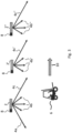
- FIG. 1 to 3 An example of a lighting situation is shown.
- the luminaires 2 to 2" with variable light distribution curve which can be used within the scope of this disclosure, are described in the German patent application with the same filing date and titled "Luminaire with adaptive LVK" by the same applicant.
- the luminaires 2 to 2" are mounted in an elevated position, for example the ceiling, and emit their light downwards to the user level.
- the light distribution is illustrated by the arrows 4X to 4X", where the length of the arrow indicates the light intensity in the respective solid angle, and "X" is a placeholder for a letter from "a” to "c", each of which corresponds to a different direction and/or angle at which the luminous flux leaves the luminaire.
- the outer solid angles of the light distribution must be illuminated with high intensity, here 4a to 4a" and 4c to 4c".
- FIG 1 The use of a non-controlled luminaire with a wide beam light distribution curve is illustrated. As in Figure 1 As can be seen, the light intensity of all lights 2 to 2" is identical in the respective solid angle. The light distribution is not controlled by reducing the luminous flux. In the case shown, a person in the vehicle 6, who is located in the outer area of the light cone of the light 2, would be dazzled by the light distribution with high intensity 4a in the direction of travel.
- Figure 2 shows the same starting position as Figure 1 , whereby the lights 2 to 2" in this case additionally have a sensor 8.
- This sensor enables the provision of the sensor information, which is processed by the control device of the light. If the person or the vehicle 6 approaches, indicated by the direction of travel 10, the sensors detect the approaching person or the vehicle 6 and forward this sensor information to the control unit of the light. The control unit processes the sensor information and determines the solid angle in which the vehicle approaches the light.
- the solid angle determined by the control device is the area in which the person or the vehicle 6 walks or drives through the outer light cone. Exactly this solid angle, which has a high light intensity, forms the critical area in which the person or the vehicle 6 experiences the strongest glare.
- FIGS. 4 and 5 illustrate the use of the luminaire using the example of a high-bay warehouse.
- the luminaires are, for example, Figure 1 shown, are mounted on the ceiling and illuminate the path between the shelves 12 with an elliptical light distribution 14, measured in the conical section of the area to be illuminated.
- Figure 4 represents the situation with lights whose light intensity is not controlled. This can be seen from the fact that in the area of the vehicle 6 the light distribution 14 is Figure 4 is mirror-symmetrical in front of and behind the vehicle in the direction of movement of the vehicle. The illuminance on the illuminated surface is similar at every point in order to produce the most homogeneous illumination possible of the rectangular user plane 16.
- Figure 5 shows a Figure 4 Identical initial situation, but using controlled lights.
- the luminous flux of the light is reduced. This prevents glare for the person in the vehicle 6 and, despite a one-sidedly distorted light distribution, creates a roughly homogeneous illumination in the user plane 16. This is represented by the sharp cut-off line at the respective right edge of the light distribution 14, whereas the respective light distribution on the left side of the light cone is gently faded out (no elliptical boundary on the left half of the user plane 16).
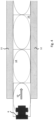
- the Figures 6 and 7 represent another application example for the lamp 18.
- the lamp 18 illuminates the two streets 28a and 28b of a two-lane road with two light cones per lane (left of the lamps 20a and 20d, and right of the lamps 20b and 20c).
- vehicles 22a and 22b are traveling in the direction 26a and 26b towards the light, they are detected by the sensor 24.
- Figure 6 shows the case where the two vehicles 22a and 22b are moving towards the solid angles 20a and 20c of the lamp.
- the two vehicles 22a and 22b have reached the solid angle in front of the lamp in the direction of travel of the person or the vehicle, respectively.
- the luminous flux was reduced by to avoid dazzling road users.
Landscapes
- Engineering & Computer Science (AREA)
- General Engineering & Computer Science (AREA)
- Non-Portable Lighting Devices Or Systems Thereof (AREA)
Description
- Die vorliegende Erfindung betrifft eine Leuchte zur stationären Montage in einem Innenbereich (z.B. Hochregallager oder Flur) oder Außenbereich (z.B. Verkehrsweg oder Parkplatz) mit einer veränderbaren Lichtverteilung.
- Für Lichtinstallationen im Innen- und Außenbereich werden in vielen Anwendungsbereichen Leuchten mit einer breiten Lichtverteilung eingesetzt, um die gleichmäßige Beleuchtung einer großen Fläche mit möglichst wenig Leuchten zu erreichen. Um trotz der großen auszuleuchtenden Fläche eine ausreichende Beleuchtungsstärke zu erreichen, müssen einerseits hohe Lichtströme verwendet werden und andererseits muss ein großer Anteil des von der Leuchte ausgesendeten Lichts die Leuchte unter sehr kleinen Winkeln (gegenüber der Horizontalen) verlassen. Diese beiden Maßnahmen erhöhen jedoch die Blendwirkung der Leuchte. Insbesondere für Tätigkeiten mit kritischen Sehaufgaben gibt es daher Vorschriften zur Blendungsbegrenzung (z.B. DIN EN 13201). Um für kritische Sehaufgaben eine Blendung zu vermeiden und dennoch eine hohe Beleuchtungsstärke der Anwenderebene zu erreichen, müssen daher geringere Leuchtenabstände gewählt werden.
- Ein Nachteil besteht dabei darin, dass einerseits höhere Installations- und Anschaffungskosten anfallen, und weiterhin eine größere Anzahl von Leuchten gewartet werden muss.
- Eine Leuchte gemäß dem Oberbegriff des Anspruchs 1 ist aus der
US 2014/320023 A1 bekannt. Weitere Beleuchtungsvorrichtungen, welche insbesondere zur Verringerung der Blendung eingerichtet sind, sind aus derUS 2018/324929 A1 ,US 2016/150614 A1 undCN 109724020 A bekannt. - Aufgabe der vorliegenden Erfindung ist es, eine Leuchte mit veränderbarer Lichtverteilung bereitzustellen, die die Blendung einer Person, ggf. in einem Fahrzeug, reduziert.
- Gelöst wird die Aufgabe durch einen Leuchte nach Anspruch 1.
- Eine Besonderheit der erfindungsgemäßen Leuchte besteht in der Art der Blendvermeidung. Eine Steuereinrichtung der Leuchte empfängt eine Sensorinformation und wertet diese aus, um einen Raumwinkel der Leuchte zu bestimmen, in welchem sich eine Person bzw. ein Fahrzeug der Leuchte nähert. Durch das Ansteuern der Lichtverteilung der Leuchte wird der Lichtstrom der Leuchte in dem genannten Raumwinkel, in dem sich die Person bzw. das Fahrzeug nähert, verringert. Durch das gezielte Verringern des Lichtstroms in dem Raumwinkel, in dem sich eine Person bzw. ein Fahrzeug der Leuchte nähert und folglich die Blickrichtung zur Leuchte weist, wird eine mögliche Blendung der Person bzw. des Fahrzeuginsassen stark verringert, da die Lichtstärke (Lichtstrom pro Raumwinkel) am Aufenthaltsort der Person bzw. des Fahrzeugs reduziert wird. Zugleich kann die Leuchte jeden anderen Raumwinkel mit einer großen Lichtintensität ausleuchten solange keine Person ggf. in einem Fahrzeug mit Blickrichtung auf die Leuchte in diesen Raumwinkeln anwesend ist. Folglich kann bei der Planung und Installation der Beleuchtungsanlage eine geringere Anzahl an Leuchten, welche mit einem größeren Abstand zueinander stehen, vorgesehen werden.
- Gemäß einer bevorzugten Ausführungsform weist die Leuchte in einer vertikalen Schnittebene durch die Leuchte (C(0-180)-Ebene) eine breitstrahlende Lichtstärkeverteilungskurve (LVK) auf. Die breitstrahlende LVK ermöglicht es mit der Leuchte insbesondere länglich geschnittene Flächen (z.B. Gänge oder Straßen) mit großen Leuchtenabständen zu beleuchten.
- Gemäß einer bevorzugten Ausführungsform ist die Leuchte zur Befestigung an einer Gebäudestruktur, wie beispielsweise einer Wand oder Decke, oder an einem Mast, beispielsweise ein Lichtmast, eingerichtet. Dies vereinfacht das Anbringen der Leuchte an einer höher gelegenen Gebäudestruktur, beispielsweise an der Decke eines Hochregallagers, oder einer Verkehrsstruktur, beispielsweise ein Mast für eine Straßenbeleuchtungseinheit. Durch das Anbringen der Leuchte an dieser Struktur kann insbesondere die Möglichkeit der großflächigen Beleuchtung optimal ausgenutzt werden.
- Gemäß einer bevorzugten Ausführungsform kann eine Leuchte mehrere Lichtquellen aufweisen und das Anpassen des Lichtstroms durch ein Dimmen wenigstens einer der mehreren Lichtquellen geschehen. Das Anordnen von mehreren Lichtquellen in der Leuchte bietet den Vorteil, dass die Lichtquellen unabhängig voneinander ausgerichtet werden können und somit Lichtströme in unterschiedliche Raumwinkel der Leuchte abgeben können. Zugleich bietet diese Form der Anordnung von dimmbaren Lichtquellen die Möglichkeit, den Lichtstrom in einem bestimmten Raumwinkel der Leuchte durch bloßes Dimmen der betreffenden Lichtquellen, deren Lichtstrom in diesen Raumwinkel der Leuchte gesendet wird, zu verringern. Folglich ermöglicht diese Art der Leuchtenausführung die Verwendung eines kostengünstigen und wartungsarmen Leuchtenmoduls.
- Gemäß einer bevorzugten Ausführungsform weist die Leuchte wenigstens eine bewegliche Optik auf. Das Anpassen des Lichtstroms erfolgt durch ein Verlagern der Optik gegenüber der Lichtquelle. Diese Ausführungsform ermöglicht die Verwendung einer oder mehreren zentral angeordneten, lichtstarken Lichtquellen. Ferner bietet das Verwenden einer Optik die Möglichkeit, komplexe Strukturen mit einer hochvariablen Lichtverteilung auszuleuchten.
- Erfindungsgemäß ist die Leuchte zur Beleuchtung mehrerer, insbesondere parallel zueinander verlaufender Straßen oder anderen Verkehrswegen eingerichtet. Die Steuerung der Leuchte verarbeitet eine Sensorinformation, um für mehrere Personen und/oder Fahrzeuge Raumwinkel der Leuchte, in welchen sich jeweils eine Person bzw. ein Fahrzeug der Leuchte nähert, zu bestimmen. Das Verringern der Lichtströme der Leuchte erfolgt anschließend in den jeweiligen Raumwinkeln. Dies bietet den Vorteil, dass beispielsweise bei nebeneinanderliegenden, mehrspurigen Straßen die Verwendung einer einzigen Leuchte für jeweils einen Längenabschnitt der Straße ausreicht.
- Erfindungsgemäß ist die Steuerung ferner dazu eingerichtet, die Lichtverteilung in dem Raumwinkel der Leuchte, in welchem sich eine Person bzw. ein Fahrzeug befindet und sich von der Leuchte entfernt, zu erhöhen. Mit Rückbezug auf die zuvor genannte bevorzugte Ausführungsform, erfolgt das Erhöhen der Lichtverteilung in mehreren Raumwinkeln der Leuchte, in welchen sich jeweils eine Person bzw. ein Fahrzeug von der Leuchte entfernt. Diese Ausführungsform bietet den Vorteil, dass der Beleuchtungsreduzierung mit verringerter Lichtintensität in einem Raumwinkel möglichst kurz gehalten werden kann, um die Ausleuchtung für nachfolgende Person bzw. das Fahrzeug zu verbessern. Ferner vereinfacht ein zusätzliches Erhöhen des Lichtstroms im betreffenden Raumwinkel das Erkennen der Person bzw. des Fahrzeugs, welche bzw. welches den erhellten Raumwinkel passiert und somit von hinten stärker angestrahlt wird. Gemäß einer bevorzugten Ausführungsform wird die Sensorinformation durch wenigstens einen Sensor bereitgestellt, wobei der Sensor in der Leuchte verbaut ist. Dies bietet den Vorteil, dass die Leuchte selbstständig ihre Umgebung erfassen kann und somit nur Stromgebunden ist.
- Gemäß einer bevorzugten Ausführungsform wird die Sensorinformation durch einen Sensor bereitgestellt, welcher extern von der Leuchte angeordnet ist, wobei die Leuchte eine Schnittstelle zum Empfangen der Sensorinformation aufweist. Diese Anordnung bietet die Möglichkeit, einen Sensor mit einer sehr großen Erfassungsreichweite zentral anzubringen, wobei die Sensorinformation an die Leuchte, und ggf. weitere Leuchten, gesendet wird.
- Gemäß einer bevorzugten Ausführungsform wird die Sensorinformation durch mehrere Sensoren bereitgestellt, welche sowohl in der Leuchte verbaut sind, als auch extern von der Leuchte angebracht sein können. Diese Ausführungsform ermöglicht es, dass die Leuchte beispielsweise mittels Kurzstreckensensoren die unmittelbare Umgebung erfasst, während extern angebrachte Langstreckensensoren zusätzliche Sensorinformationen an die Leuchte senden. Dadurch kann einerseits die Genauigkeit der Ansteuerung der Leuchte verbessert werden, andererseits aber auch ein ausfallsicheres System bereitgestellt werden.
- Gemäß einer bevorzugten Ausführungsform ist die Sensoreinrichtung ein Radarsensor, ein Ultraschallsensor, ein Hochfrequenzsensor, ein Mikrowellensensor, ein Kamerasensor, ein LIDAR-Sensor, Helligkeitssensor, ein Leuchtdichte-Sensor, und/oder ein Infrarotsensor. Ein Radarsensor ist zur Erfassung von langen Strecken, beispielsweise einer Straße, und insbesondere schnellen Fahrzeugen, beispielsweise auf einer Bundesstraße, geeignet. Ein Ultraschallsensor ermöglicht die präzise Überwachung von kurzen und mittleren Distanzen (ohne verdeckte Sichtachse). Ein Hochfrequenzsensor kann insbesondere zur hochpräzisen Überwachung im Innenraum eingesetzt werden. Ein Mikrowellensensor kann insbesondere zur Überwachung von Bereichen mit versperrter Sichtachse, beispielsweise von Regalen oder dünnen Wänden, verwendet werden. Ein Kamerasensor kann insbesondere zu Überwachung und Auswertung komplexer Situationen verwendet werden. Ein LIDAR-Sensor (light detection and ranging) kann für die 360°-Überwachung großer Flächen mittels eines Lasers eingesetzt werden. Ein Helligkeitssensor kann für die Detektion von Hell-Dunkel-Änderungen verwendet werden. Ein Leuchtdichtesensor kann insbesondere zur Detektion von leuchtenden Strukturen, beispielsweise sich annäherndem Scheinwerferlicht, genutzt werden. Ein Infrarotsensor kann zum Erfassen von Temperaturänderungen, beispielsweise durch sich nähernde Personen, genutzt werden. Kombinationen der Sensoren sind ebenso möglich.
- Weitere Vorteile und Merkmale werden aus der nachfolgenden Beschreibung bevorzugter, nicht beanspruchter Ausführungsformen deutlich, die in Verbindung mit den Figuren gegeben wird. In den Figuren ist folgendes dargestellt:
- Figur 1
- zeigt eine perspektivische Ansicht konventioneller Leuchten mit einem Fahrzeug.
- Figur 2
- zeigt eine Ansicht gemäß
Figur 1 mit Leuchten und das Dimmen des Lichtstroms aufgrund des sich nähernden Fahrzeugs. - Figur 3
- illustriert das Dimmen des Lichtstroms aufgrund des Fahrzeugs aus
Figur 2 , welches die erste Leuchte passiert hat. - Figur 4
- zeigt perspektivische die Ausleuchtung eines Hochregallagers mit konventionellen Leuchten und einem sich bewegenden Fahrzeug.
- Figur 5
- zeigt die blendfreie Ausleuchtung eines Hochregallagers gemäß
Figur 4 mit Leuchten. - Figur 6
- zeigt perspektivische die Ausleuchtung eines zweispurigen Wegs mit einer Leuchte und zwei sich nähernden Fahrzeugen.
- Figur 7
- illustriert die veränderte Lichtverteilung zum Verhindern der Blendung der Fahrzeuge aus
Figur 6 . - In den
Figuren 1 bis 3 wird beispielhaft eine Beleuchtungssituation dargestellt. Die Leuchten 2 bis 2" mit veränderbarer Lichtverteilungskurve, welche im Rahmen dieser Offenbarung verwendet werden können, sind in der deutschen Patentanmeldung mit selben Anmeldetag und mit dem Titel "Leuchte mit adaptiver LVK" derselben Anmelderin beschrieben. Im Beispiel derFiguren 1 bis 3 sind die Leuchten 2 bis 2" an einer erhöhten Position angebracht, beispielsweise der Decke, und geben ihr Licht nach unten auf die Anwenderebene ab. Die Lichtverteilung wird mit den Pfeilen 4X bis 4X" verdeutlicht, wobei die Länge des Pfeils die Lichtintensität in dem betreffenden Raumwinkel veranschaulicht, und "X" Platzhalter für einen Buchstaben von "a" bis "c" ist, welcher jeweils einer unterschiedlichen Richtung und/oder einem unterschiedlichen Winkel zugeordnet ist, unter dem der Lichtstrom die Leuchte verlässt. Um eine gleichmäßige Leuchtdichte zu erreichen, müssen die äußeren Raumwinkel der Lichtverteilung mit hoher Intensität ausgeleuchtet werden, hier 4a bis 4a" und 4c bis 4c". - In
Figur 1 wird die Verwendung einer nicht-gesteuerten Leuchte mit breitstrahlender Lichtverteilungskurve illustriert. Wie inFigur 1 zu erkennen ist, ist die Lichtintensität aller Leuchten 2 bis 2" im jeweiligen Raumwinkel identisch. Es erfolgt keine Ansteuerung der Lichtverteilung durch ein Verringern des Lichtstroms. Im dargestellten Fall, würde eine Person im Fahrzeug 6, welche sich im äußeren Bereich des Lichtkegels der Leuchte 2 befindet, durch die in Fahrtrichtung liegende Lichtverteilung mit hoher Intensität 4a geblendet werden. -
Figur 2 zeigt dieselbe Ausgangslage wieFigur 1 , wobei die Leuchten 2 bis 2" im vorliegenden Fall zusätzlich über einen Sensor 8 verfügen. Dieser Sensor ermöglicht die Bereitstellung der Sensorinformation, welche von der Steuereinrichtung der Leuchte verarbeitet wird. Nähert sich die Person bzw. das Fahrzeug 6, angezeigt durch die Fahrtrichtung 10, erkennen die Sensoren die sich nähernde Personen oder das Fahrzeug 6 und geben diese Sensorinformationen an das Steuergerät der Leuchte weiter. Das Steuergerät verarbeitet die Sensorinformation und bestimmt den Raumwinkel, in welchem sich das Fahrzeug der Leuchte nähert. Der von der Steuereinrichtung bestimmte Raumwinkel ist der Bereich, in welchem die Person bzw. das Fahrzeug 6 den äußeren Lichtkegel durchschreitet oder -fährt. Genau dieser Raumwinkel, welcher eine hohe Lichtintensität aufweist, bildet den kritischen Bereich, in welchem die Person bzw. das Fahrzeug 6 die stärkste Blendung erfahren. Wie ausFigur 2 hervorgeht, wurde die Lichtverteilung der Leuchte in diesem Bereich angesteuert, um den Lichtstrom in diesem Raumwinkel (Lichtintensität) zu verringern. Dies zeigt sich im direkten Vergleich zwischenFigur 1 undFigur 2 durch das Fehlen der Lichtverteilung mit hoher Intensität in Fahrtrichtung 4a, welche die Person bzw. das Fahrzeug 6 blenden würde. - In
Figur 3 wird der weitere Regelverlauf des Lichtsystems illustriert. Die Person bzw. das Fahrzeug 6, welches die Bewegungsrichtung 10 beibehält, wird nun, im Vergleich zuFigur 2 , zu einem späteren Zeitpunkt dargestellt. Im Vergleich zuFigur 2 ist die Lichtverteilung mit hoher Intensität in Fahrtrichtung 4a der Leuchte 2 nicht mehr verringert, da die Person bzw. das Fahrzeug 6 diese Leuchte bereits passiert hat. Aufgrund der Fahrtrichtung 10 und der Position der Person bzw. des Fahrzeugs 6, sind nun die Lichtverteilungen mit hoher Intensität in Fahrtrichtung 4a' und 4a" verringert, um eine Blendung zu verhindern. Alternativ kann, je nach Einsatzort, das Verringern des Lichtstroms durch ein geringes Abdunkeln im betreffenden Raumwinkel erfolgen. Ferner kann es in bestimmten Anwendungsfällen, beispielsweise bei der Beleuchtung im Tunnel, hilfreich sein, bei einem sich nähernden Fahrzeug bereits Lichtströme von weiteren, in Fahrtrichtung nachfolgenden Leuchten abzudunkeln, um die Hell-Dunkel-Grenzen-Verschiebung in einem geeigneten Abstand (z.B. empfohlener Mindestabstand zum vorausfahrenden Fahrzeug) homogen vor dem Fahrzeug zu halten. Das erneute Erhöhen des Lichtstroms in zuvor abgedunkelten Raumwinkeln kann erfolgen, unmittelbar nachdem die Person bzw. das Fahrzeug 6 den für die Blendung kritischen Raumwinkel verlassen haben, oder beispielsweise auch erst nach Ablauf einer Wartezeit. DieFiguren 4 und5 illustrieren die Verwendung der Leuchte am Beispiel eines Hochregallagers. Die Leuchten sind, wie beispielsweise inFigur 1 dargestellt, an der Decke angebracht und erhellen den Weg zwischen den Regalen 12 mit einer elliptischen Lichtverteilung 14, gemessen im Kegelmantelschnitt der zu beleuchtenden Fläche. -
Figur 4 stellt die Situation mit Leuchten dar, deren Lichtintensität nicht gesteuert wird. Dies ist daran zu erkennen, dass im Bereich des Fahrzeugs 6 die Lichtverteilung 14 inFigur 4 in Bewegungsrichtung des Fahrzeugs vor und hinter dem Fahrzeug spiegelsymmetrisch ist. Die Beleuchtungsstärke auf der beleuchteten Fläche ist an jedem Punkt ähnlich groß, um eine möglichst homogene Ausleuchtung der rechteckigen Anwenderebene 16 zu erzeugen. -
Figur 5 zeigt eine zuFigur 4 identische Ausgangssituation, jedoch unter der Verwendung von gesteuerten Leuchten. Im jeweiligen Raumwinkel, aus dem sich das Fahrzeug in Fahrtrichtung 10 der Leuchte nähert, wird der Lichtstrom der Leuchte verringert. Dadurch wird erreicht, dass die Blendung der Person im Fahrzeugs 6 vermieden wird und trotz einer einseitig verzerrten Lichtverteilung eine etwa homogene Ausleuchtung in der Anwenderebene 16 erzeugt wird. Dargestellt wird dies durch die scharfe Hell-Dunkel-Grenze am jeweiligen rechten Rand der Lichtverteilung 14, wohingegen die jeweilige Lichtverteilung auf der linken Seite des Lichtkegels sanft ausgeblendet ist (keine elliptische Begrenzung auf der linken Hälfte der Anwenderebene 16). - Die
Figuren 6 und7 stellen ein weiteres Anwendungsbeispiel für die Leuchte 18 dar. Die Leuchte 18 leuchtet die beiden Straßen 28a und 28b einer zweispurigen Straße mit jeweils zwei Lichtkegeln pro Weg aus (links der Leuchte 20a und 20d, und rechts der Leuchte 20b und 20c). Bewegen sich, wie inFigur 6 und7 dargestellt, Fahrzeuge 22a und 22b in Fahrtrichtung 26a und 26b auf die Leuchte zu, werden diese vom Sensor 24 erfasst. -
Figur 6 zeigt den Fall, dass sich die beiden Fahrzeuge 22a und 22b auf die Raumwinkel 20a und 20c der Leuchte zubewegen. In der Darstellung vonFigur 7 haben die beiden Fahrzeuge 22a und 22b den jeweils in Fahrtrichtung der Person bzw. des Fahrzeugs vor der Leuchte liegenden Raumwinkel erreicht. In diese Raumwinkel 20a und 20c wurde der Lichtstrom verringert, um eine Blendung der Verkehrsteilnehmer zu vermeiden. -
- 2-2"
- Leuchte
- 4a-4a"
- Lichtstärke
- 4b-4b"
- Lichtstärke
- 4c-4c"
- Lichtstärke
- 6
- Fahrzeug
- 8
- Sensor
- 10
- Fahrtrichtung
- 12
- Regalwand
- 14
- Lichtverteilung
- 16
- Anwenderebene
- 18
- Leuchte
- 20a, 20b
- Raumwinkel in Fahrtrichtung auf unteren Weg
- 20c, 20d
- Raumwinkel entgegen der Fahrtrichtung
- 22a, 22b
- Fahrzeug
- 24
- Sensor
- 26a, 26b
- Fahrtrichtung
- 28a, 28b
- Spur einer Straße
Claims (10)
- Leuchte (2) zur stationären Montage in einem Innen- oder Außenraum mit einer veränderbaren Lichtverteilung,wobei die Leuchte eine Steuereinrichtung (8, 24) aufweist, die eingerichtet ist, um eine Sensorinformation zu empfangen, durch die Sensorinformation einen Raumwinkel der Leuchte (2), in welchem sich eine Person oder ein Fahrzeug (6) der Leuchte nähert, zu bestimmen, und die Lichtverteilung der Leuchte (2) anzusteuern, um einen Lichtstrom der Leuchte, der in den genannten Raumwinkel (4a) abgegeben wird, zu verringern,wobei die Steuerung ferner eingerichtet ist, um den Lichtstrom in einem Raumwinkel der Leuchte (4c), in welchem sich die Person oder Fahrzeug befindet und sich von der Leuchte entfernt, zu erhöhen,wobei die Leuchte (2) zur Beleuchtung mehrerer, insb. parallel zueinander verlaufender Straßen (28a, 28b) eingerichtet ist, unddie Steuerung eingerichtet ist, um aus der Sensorinformation für mehrere Personen und/oder Fahrzeuge (22a, 22b) Raumwinkel (20a, 20c) der Leuchte, in welchem sich jeweils eine Person oder ein Fahrzeug (22a, 22b) nähert, zu bestimmen,und die Leuchte anzusteuern, um Lichtströme der Leuchte, die in den genannten Raumwinkel (20a, 20c) abgegeben werden, zu verringern.
- Leuchte nach Anspruch 1, wobei die Leuchte (2) in der C(0-180)-Ebene eine breitstrahlende Lichtstärkeverteilungskurve aufweist.
- Leuchte nach einem der vorherigen Ansprüche, wobei die Leuchte (2) zur Befestigung an einer Gebäudestruktur, insbesondere Wand oder Decke, oder an einem Mast eingerichtet ist.
- Leuchte nach einem der vorherigen Ansprüche, wobei die Leuchte (2) mehrere Leuchtquellen aufweist, und das Anpassen des Lichtstroms durch ein Dimmen wenigstens einer der mehreren Lichtquellen erfolgt.
- Leuchte nach einem der vorherigen Ansprüche, wobei die Leuchte (2) wenigstens eine bewegliche Optik aufweist, und das Anpassen des Lichtstroms durch ein Verlagern der Optik gegenüber der Lichtquelle erfolgt.
- Leuchte nach Anspruch 1, wobei die Steuerung eingerichtet ist, um den Lichtstrom in mehreren Raumwinkeln (20b, 20d) der Leuchte, in welchen sich jeweils eine Person oder ein Fahrzeug von der Leuchte entfernt, zu erhöhen.
- Leuchte nach einem der vorherigen Ansprüche, wobei die Sensorinformation durch wenigstens einen Sensor (8, 24) bereitgestellt wird, und der Sensor (8, 24) in der Leuchte verbaut ist.
- Leuchte nach einem der Ansprüche 1 bis 6, wobei die Leuchte eine Schnittstelle aufweist, die einrichtet ist, um ein Sensorinformation, die durch einen extern von der Leuchte verbauten Sensor bereitgestellt wird, zu empfangen.
- Leuchte nach einem der Ansprüche 1 bis 6, wobei die Sensorinformation durch mehrere Sensoren bereitgestellt wird, wobei wenigstens ein Sensor (8, 24) in der Leuchte verbaut ist, und wenigstens eine weitere Sensorinformationen durch einen extern von der Leuchte verbauten Sensor bereitgestellt wird, und die Leuchte eine Schnittstelle aufweist, die einrichtet ist, um die Sensorinformation, die durch den extern von der Leuchte verbauten Sensor bereitgestellt wird, zu empfangen.
- Leuchte nach Anspruche 7 bis 9, wobei die Sensoreinrichtung ein Radarsensor, einen Ultraschallsensor, ein Hochfrequenz-Sensor, ein Mikrowellensensor, ein Kamerasensor, ein LIDAR-Sensor, ein Helligkeitssensor, ein Leuchtdichtesensor und/oder ein Infrarot-Sensor ist.
Applications Claiming Priority (1)
| Application Number | Priority Date | Filing Date | Title |
|---|---|---|---|
| DE102019118283.2A DE102019118283A1 (de) | 2019-07-05 | 2019-07-05 | Personen- und/oder Fahrzeugbezogene Entblendung von Leuchten |
Publications (3)
| Publication Number | Publication Date |
|---|---|
| EP3760914A1 EP3760914A1 (de) | 2021-01-06 |
| EP3760914B1 EP3760914B1 (de) | 2022-03-09 |
| EP3760914B2 true EP3760914B2 (de) | 2025-05-07 |
Family
ID=71465094
Family Applications (1)
| Application Number | Title | Priority Date | Filing Date |
|---|---|---|---|
| EP20183768.9A Active EP3760914B2 (de) | 2019-07-05 | 2020-07-02 | Personen- und fahrzeugbezogene entblendung von leuchten |
Country Status (2)
| Country | Link |
|---|---|
| EP (1) | EP3760914B2 (de) |
| DE (1) | DE102019118283A1 (de) |
Citations (5)
| Publication number | Priority date | Publication date | Assignee | Title |
|---|---|---|---|---|
| US20050018434A1 (en) † | 2003-05-30 | 2005-01-27 | Ronald Giuliano | Positional luminaire |
| EP2789213A1 (de) † | 2011-12-08 | 2014-10-15 | Koninklijke Philips N.V. | Leuchte |
| EP3089559A1 (de) † | 2015-04-10 | 2016-11-02 | Google, Inc. | Dynamische weglichthelligkeit auf basis von grösse und entfernung von bewegung/gegenstand, der sich der vorrichtung nähert |
| WO2018048528A1 (en) † | 2016-09-08 | 2018-03-15 | Osram Sylvania Inc. | Spatially and temporally smooth occupancy lighting |
| US9930752B2 (en) † | 2015-11-10 | 2018-03-27 | General Electric Company | Image sensor controlled lighting fixture |
Family Cites Families (5)
| Publication number | Priority date | Publication date | Assignee | Title |
|---|---|---|---|---|
| DE102007061160A1 (de) * | 2007-12-17 | 2009-06-25 | Semperlux Aktiengesellschaft - Lichttechnische Werke - | Außenleuchte |
| US9338850B2 (en) * | 2013-04-24 | 2016-05-10 | GE Lighting Solutions, LLC | Lighting systems and methods providing active glare control |
| US9877374B2 (en) * | 2014-11-25 | 2018-01-23 | Cree, Inc. | Lighting apparatus and methods providing variable illumination characteristics based on object detection |
| US10225910B2 (en) * | 2017-05-05 | 2019-03-05 | Osram Sylvania Inc. | Systems and methods for glare-free adaptive lighting |
| CN109724020A (zh) * | 2017-10-30 | 2019-05-07 | 光宝电子(广州)有限公司 | 户外照明结构及其操作方法 |
-
2019
- 2019-07-05 DE DE102019118283.2A patent/DE102019118283A1/de active Pending
-
2020
- 2020-07-02 EP EP20183768.9A patent/EP3760914B2/de active Active
Patent Citations (5)
| Publication number | Priority date | Publication date | Assignee | Title |
|---|---|---|---|---|
| US20050018434A1 (en) † | 2003-05-30 | 2005-01-27 | Ronald Giuliano | Positional luminaire |
| EP2789213A1 (de) † | 2011-12-08 | 2014-10-15 | Koninklijke Philips N.V. | Leuchte |
| EP3089559A1 (de) † | 2015-04-10 | 2016-11-02 | Google, Inc. | Dynamische weglichthelligkeit auf basis von grösse und entfernung von bewegung/gegenstand, der sich der vorrichtung nähert |
| US9930752B2 (en) † | 2015-11-10 | 2018-03-27 | General Electric Company | Image sensor controlled lighting fixture |
| WO2018048528A1 (en) † | 2016-09-08 | 2018-03-15 | Osram Sylvania Inc. | Spatially and temporally smooth occupancy lighting |
Also Published As
| Publication number | Publication date |
|---|---|
| DE102019118283A1 (de) | 2021-01-07 |
| EP3760914A1 (de) | 2021-01-06 |
| EP3760914B1 (de) | 2022-03-09 |
Similar Documents
| Publication | Publication Date | Title |
|---|---|---|
| DE102012016782B4 (de) | Verfahren zum Betreiben eines Scheinwerfersystems und Scheinwerfersystem für ein Fahrzeug | |
| AT509035B1 (de) | Beleuchtungsvorrichtung und beleuchtungssystem | |
| EP2567866B1 (de) | Verfahren zum Betreiben eines Scheinwerfers eines Kraftfahrzeugs | |
| EP3548337B1 (de) | Steuern eines scheinwerfers eines kraftfahrzeuges | |
| WO2010124315A1 (de) | Steuerverfahren für eine beleuchtung | |
| DE19716784A1 (de) | Scheinwerferanlage für Fahrzeuge | |
| DE102007048717A1 (de) | Vorrichtung und Verfahren zum Reduzieren der Lichtblendung eines Fahrers eines Kraftfahrzeugs | |
| DE102007002809A1 (de) | Verfahren zum gepulsten Betrieb einer Beleuchtungseinrichtung mit Leuchtdioden (LED) für Kraftfahrzeuge | |
| DE102011002894A1 (de) | Kollisionsabhängige Fahrerbeleuchtung | |
| EP3770488A1 (de) | Strassenleuchte mit kommunikationsschnittstelle zu fahrzeugen | |
| DE102019131052A1 (de) | Lidar-integrierte beleuchtungsvorrichtung für ein fahrzeug | |
| DE102019214319A1 (de) | Verfahren zur Verbesserten Umfelderfassung | |
| EP3013125B1 (de) | Adaptive strassenleuchte | |
| EP3760914B2 (de) | Personen- und fahrzeugbezogene entblendung von leuchten | |
| DE102008008880B4 (de) | Fahrzeugleuchtensystem | |
| DE102014005423A1 (de) | Beleuchtungsvorrichtung und Verfahren zur Steuerung einer Beleuchtungseinheit eines Fahrzeugs | |
| DE102013006045A1 (de) | Verfahren zur Steuerung eines Scheinwerfers | |
| DE102016200323A1 (de) | Verfahren zur Erkennung einer Blendungssituation und zur entsprechenden Ansteuerung zumindest eines lichtaussendenden Elements | |
| DE102004055882A1 (de) | Kraftfahrzeug mit einer Beleuchtungseinrichtung umfassend ein Steuergerät und ein über das Steuergerät zum Ausleuchten einer Kurve in Abhängigkeit des über einen Lenkwinkelsensor erfassten Lenkwinkels ansteuerbares Leuchtmittel | |
| DE69120492T2 (de) | Strassenbeleuchtungsverfahren und -vorrichtung mit horizontalem, auf die Rückseite der Fahrzeuge gerichtetem Lichtstrom | |
| EP3770489B1 (de) | Adaptive strassenleuchte mit personendetektor | |
| DE202004006444U1 (de) | Einrichtung zur Sicherung eines Fußgängerüberweges | |
| DE102012006692A1 (de) | Beleuchtungseinrichtung sowie entsprechendes Verfahren zur Beleuchtung, insbesondere für ein Schienenfahrzeug | |
| DE102011120223A1 (de) | Anordnung und Verfahren zur Verhinderungvon Wildunfällen | |
| DE202005002515U1 (de) | Einrichtung zur Sicherung eines Fußgängerüberweges |
Legal Events
| Date | Code | Title | Description |
|---|---|---|---|
| PUAI | Public reference made under article 153(3) epc to a published international application that has entered the european phase |
Free format text: ORIGINAL CODE: 0009012 |
|
| STAA | Information on the status of an ep patent application or granted ep patent |
Free format text: STATUS: THE APPLICATION HAS BEEN PUBLISHED |
|
| AK | Designated contracting states |
Kind code of ref document: A1 Designated state(s): AL AT BE BG CH CY CZ DE DK EE ES FI FR GB GR HR HU IE IS IT LI LT LU LV MC MK MT NL NO PL PT RO RS SE SI SK SM TR |
|
| AX | Request for extension of the european patent |
Extension state: BA ME |
|
| STAA | Information on the status of an ep patent application or granted ep patent |
Free format text: STATUS: REQUEST FOR EXAMINATION WAS MADE |
|
| 17P | Request for examination filed |
Effective date: 20210702 |
|
| RBV | Designated contracting states (corrected) |
Designated state(s): AL AT BE BG CH CY CZ DE DK EE ES FI FR GB GR HR HU IE IS IT LI LT LU LV MC MK MT NL NO PL PT RO RS SE SI SK SM TR |
|
| RIC1 | Information provided on ipc code assigned before grant |
Ipc: F21W 131/103 20060101ALN20210812BHEP Ipc: F21V 23/04 20060101ALI20210812BHEP Ipc: F21S 8/04 20060101AFI20210812BHEP |
|
| GRAP | Despatch of communication of intention to grant a patent |
Free format text: ORIGINAL CODE: EPIDOSNIGR1 |
|
| STAA | Information on the status of an ep patent application or granted ep patent |
Free format text: STATUS: GRANT OF PATENT IS INTENDED |
|
| RIC1 | Information provided on ipc code assigned before grant |
Ipc: F21W 131/103 20060101ALN20210910BHEP Ipc: F21V 23/04 20060101ALI20210910BHEP Ipc: F21S 8/04 20060101AFI20210910BHEP |
|
| INTG | Intention to grant announced |
Effective date: 20211006 |
|
| GRAS | Grant fee paid |
Free format text: ORIGINAL CODE: EPIDOSNIGR3 |
|
| GRAA | (expected) grant |
Free format text: ORIGINAL CODE: 0009210 |
|
| STAA | Information on the status of an ep patent application or granted ep patent |
Free format text: STATUS: THE PATENT HAS BEEN GRANTED |
|
| AK | Designated contracting states |
Kind code of ref document: B1 Designated state(s): AL AT BE BG CH CY CZ DE DK EE ES FI FR GB GR HR HU IE IS IT LI LT LU LV MC MK MT NL NO PL PT RO RS SE SI SK SM TR |
|
| REG | Reference to a national code |
Ref country code: CH Ref legal event code: EP Ref country code: AT Ref legal event code: REF Ref document number: 1474449 Country of ref document: AT Kind code of ref document: T Effective date: 20220315 |
|
| REG | Reference to a national code |
Ref country code: DE Ref legal event code: R096 Ref document number: 502020000773 Country of ref document: DE |
|
| REG | Reference to a national code |
Ref country code: IE Ref legal event code: FG4D Free format text: LANGUAGE OF EP DOCUMENT: GERMAN |
|
| REG | Reference to a national code |
Ref country code: LT Ref legal event code: MG9D |
|
| REG | Reference to a national code |
Ref country code: NL Ref legal event code: MP Effective date: 20220309 |
|
| PG25 | Lapsed in a contracting state [announced via postgrant information from national office to epo] |
Ref country code: SE Free format text: LAPSE BECAUSE OF FAILURE TO SUBMIT A TRANSLATION OF THE DESCRIPTION OR TO PAY THE FEE WITHIN THE PRESCRIBED TIME-LIMIT Effective date: 20220309 Ref country code: RS Free format text: LAPSE BECAUSE OF FAILURE TO SUBMIT A TRANSLATION OF THE DESCRIPTION OR TO PAY THE FEE WITHIN THE PRESCRIBED TIME-LIMIT Effective date: 20220309 Ref country code: NO Free format text: LAPSE BECAUSE OF FAILURE TO SUBMIT A TRANSLATION OF THE DESCRIPTION OR TO PAY THE FEE WITHIN THE PRESCRIBED TIME-LIMIT Effective date: 20220609 Ref country code: LT Free format text: LAPSE BECAUSE OF FAILURE TO SUBMIT A TRANSLATION OF THE DESCRIPTION OR TO PAY THE FEE WITHIN THE PRESCRIBED TIME-LIMIT Effective date: 20220309 Ref country code: HR Free format text: LAPSE BECAUSE OF FAILURE TO SUBMIT A TRANSLATION OF THE DESCRIPTION OR TO PAY THE FEE WITHIN THE PRESCRIBED TIME-LIMIT Effective date: 20220309 Ref country code: BG Free format text: LAPSE BECAUSE OF FAILURE TO SUBMIT A TRANSLATION OF THE DESCRIPTION OR TO PAY THE FEE WITHIN THE PRESCRIBED TIME-LIMIT Effective date: 20220609 |
|
| PG25 | Lapsed in a contracting state [announced via postgrant information from national office to epo] |
Ref country code: LV Free format text: LAPSE BECAUSE OF FAILURE TO SUBMIT A TRANSLATION OF THE DESCRIPTION OR TO PAY THE FEE WITHIN THE PRESCRIBED TIME-LIMIT Effective date: 20220309 Ref country code: GR Free format text: LAPSE BECAUSE OF FAILURE TO SUBMIT A TRANSLATION OF THE DESCRIPTION OR TO PAY THE FEE WITHIN THE PRESCRIBED TIME-LIMIT Effective date: 20220610 Ref country code: FI Free format text: LAPSE BECAUSE OF FAILURE TO SUBMIT A TRANSLATION OF THE DESCRIPTION OR TO PAY THE FEE WITHIN THE PRESCRIBED TIME-LIMIT Effective date: 20220309 |
|
| PG25 | Lapsed in a contracting state [announced via postgrant information from national office to epo] |
Ref country code: NL Free format text: LAPSE BECAUSE OF FAILURE TO SUBMIT A TRANSLATION OF THE DESCRIPTION OR TO PAY THE FEE WITHIN THE PRESCRIBED TIME-LIMIT Effective date: 20220309 |
|
| PG25 | Lapsed in a contracting state [announced via postgrant information from national office to epo] |
Ref country code: SM Free format text: LAPSE BECAUSE OF FAILURE TO SUBMIT A TRANSLATION OF THE DESCRIPTION OR TO PAY THE FEE WITHIN THE PRESCRIBED TIME-LIMIT Effective date: 20220309 Ref country code: SK Free format text: LAPSE BECAUSE OF FAILURE TO SUBMIT A TRANSLATION OF THE DESCRIPTION OR TO PAY THE FEE WITHIN THE PRESCRIBED TIME-LIMIT Effective date: 20220309 Ref country code: RO Free format text: LAPSE BECAUSE OF FAILURE TO SUBMIT A TRANSLATION OF THE DESCRIPTION OR TO PAY THE FEE WITHIN THE PRESCRIBED TIME-LIMIT Effective date: 20220309 Ref country code: PT Free format text: LAPSE BECAUSE OF FAILURE TO SUBMIT A TRANSLATION OF THE DESCRIPTION OR TO PAY THE FEE WITHIN THE PRESCRIBED TIME-LIMIT Effective date: 20220711 Ref country code: ES Free format text: LAPSE BECAUSE OF FAILURE TO SUBMIT A TRANSLATION OF THE DESCRIPTION OR TO PAY THE FEE WITHIN THE PRESCRIBED TIME-LIMIT Effective date: 20220309 Ref country code: EE Free format text: LAPSE BECAUSE OF FAILURE TO SUBMIT A TRANSLATION OF THE DESCRIPTION OR TO PAY THE FEE WITHIN THE PRESCRIBED TIME-LIMIT Effective date: 20220309 Ref country code: CZ Free format text: LAPSE BECAUSE OF FAILURE TO SUBMIT A TRANSLATION OF THE DESCRIPTION OR TO PAY THE FEE WITHIN THE PRESCRIBED TIME-LIMIT Effective date: 20220309 |
|
| PG25 | Lapsed in a contracting state [announced via postgrant information from national office to epo] |
Ref country code: PL Free format text: LAPSE BECAUSE OF FAILURE TO SUBMIT A TRANSLATION OF THE DESCRIPTION OR TO PAY THE FEE WITHIN THE PRESCRIBED TIME-LIMIT Effective date: 20220309 Ref country code: IS Free format text: LAPSE BECAUSE OF FAILURE TO SUBMIT A TRANSLATION OF THE DESCRIPTION OR TO PAY THE FEE WITHIN THE PRESCRIBED TIME-LIMIT Effective date: 20220709 Ref country code: AL Free format text: LAPSE BECAUSE OF FAILURE TO SUBMIT A TRANSLATION OF THE DESCRIPTION OR TO PAY THE FEE WITHIN THE PRESCRIBED TIME-LIMIT Effective date: 20220309 |
|
| REG | Reference to a national code |
Ref country code: DE Ref legal event code: R026 Ref document number: 502020000773 Country of ref document: DE |
|
| PLAN | Information deleted related to communication of a notice of opposition and request to file observations + time limit |
Free format text: ORIGINAL CODE: EPIDOSDOBS2 |
|
| PLAX | Notice of opposition and request to file observation + time limit sent |
Free format text: ORIGINAL CODE: EPIDOSNOBS2 |
|
| PLBI | Opposition filed |
Free format text: ORIGINAL CODE: 0009260 |
|
| 26 | Opposition filed |
Opponent name: SCHOEPF, PATRICK Effective date: 20221209 |
|
| PG25 | Lapsed in a contracting state [announced via postgrant information from national office to epo] |
Ref country code: DK Free format text: LAPSE BECAUSE OF FAILURE TO SUBMIT A TRANSLATION OF THE DESCRIPTION OR TO PAY THE FEE WITHIN THE PRESCRIBED TIME-LIMIT Effective date: 20220309 |
|
| PLAX | Notice of opposition and request to file observation + time limit sent |
Free format text: ORIGINAL CODE: EPIDOSNOBS2 |
|
| PG25 | Lapsed in a contracting state [announced via postgrant information from national office to epo] |
Ref country code: SI Free format text: LAPSE BECAUSE OF FAILURE TO SUBMIT A TRANSLATION OF THE DESCRIPTION OR TO PAY THE FEE WITHIN THE PRESCRIBED TIME-LIMIT Effective date: 20220309 Ref country code: MC Free format text: LAPSE BECAUSE OF FAILURE TO SUBMIT A TRANSLATION OF THE DESCRIPTION OR TO PAY THE FEE WITHIN THE PRESCRIBED TIME-LIMIT Effective date: 20220309 |
|
| REG | Reference to a national code |
Ref country code: BE Ref legal event code: MM Effective date: 20220731 |
|
| PG25 | Lapsed in a contracting state [announced via postgrant information from national office to epo] |
Ref country code: LU Free format text: LAPSE BECAUSE OF NON-PAYMENT OF DUE FEES Effective date: 20220702 |
|
| PG25 | Lapsed in a contracting state [announced via postgrant information from national office to epo] |
Ref country code: BE Free format text: LAPSE BECAUSE OF NON-PAYMENT OF DUE FEES Effective date: 20220731 |
|
| PLBB | Reply of patent proprietor to notice(s) of opposition received |
Free format text: ORIGINAL CODE: EPIDOSNOBS3 |
|
| PG25 | Lapsed in a contracting state [announced via postgrant information from national office to epo] |
Ref country code: IT Free format text: LAPSE BECAUSE OF FAILURE TO SUBMIT A TRANSLATION OF THE DESCRIPTION OR TO PAY THE FEE WITHIN THE PRESCRIBED TIME-LIMIT Effective date: 20220309 Ref country code: IE Free format text: LAPSE BECAUSE OF NON-PAYMENT OF DUE FEES Effective date: 20220702 |
|
| PG25 | Lapsed in a contracting state [announced via postgrant information from national office to epo] |
Ref country code: MK Free format text: LAPSE BECAUSE OF FAILURE TO SUBMIT A TRANSLATION OF THE DESCRIPTION OR TO PAY THE FEE WITHIN THE PRESCRIBED TIME-LIMIT Effective date: 20220309 Ref country code: CY Free format text: LAPSE BECAUSE OF FAILURE TO SUBMIT A TRANSLATION OF THE DESCRIPTION OR TO PAY THE FEE WITHIN THE PRESCRIBED TIME-LIMIT Effective date: 20220309 |
|
| PG25 | Lapsed in a contracting state [announced via postgrant information from national office to epo] |
Ref country code: HU Free format text: LAPSE BECAUSE OF FAILURE TO SUBMIT A TRANSLATION OF THE DESCRIPTION OR TO PAY THE FEE WITHIN THE PRESCRIBED TIME-LIMIT; INVALID AB INITIO Effective date: 20200702 |
|
| PG25 | Lapsed in a contracting state [announced via postgrant information from national office to epo] |
Ref country code: TR Free format text: LAPSE BECAUSE OF FAILURE TO SUBMIT A TRANSLATION OF THE DESCRIPTION OR TO PAY THE FEE WITHIN THE PRESCRIBED TIME-LIMIT Effective date: 20220309 |
|
| PG25 | Lapsed in a contracting state [announced via postgrant information from national office to epo] |
Ref country code: MT Free format text: LAPSE BECAUSE OF FAILURE TO SUBMIT A TRANSLATION OF THE DESCRIPTION OR TO PAY THE FEE WITHIN THE PRESCRIBED TIME-LIMIT Effective date: 20220309 |
|
| APAH | Appeal reference modified |
Free format text: ORIGINAL CODE: EPIDOSCREFNO |
|
| APAW | Appeal reference deleted |
Free format text: ORIGINAL CODE: EPIDOSDREFNO |
|
| APBP | Date of receipt of notice of appeal recorded |
Free format text: ORIGINAL CODE: EPIDOSNNOA2O |
|
| APBU | Appeal procedure closed |
Free format text: ORIGINAL CODE: EPIDOSNNOA9O |
|
| PUAH | Patent maintained in amended form |
Free format text: ORIGINAL CODE: 0009272 |
|
| STAA | Information on the status of an ep patent application or granted ep patent |
Free format text: STATUS: PATENT MAINTAINED AS AMENDED |
|
| 27A | Patent maintained in amended form |
Effective date: 20250507 |
|
| AK | Designated contracting states |
Kind code of ref document: B2 Designated state(s): AL AT BE BG CH CY CZ DE DK EE ES FI FR GB GR HR HU IE IS IT LI LT LU LV MC MK MT NL NO PL PT RO RS SE SI SK SM TR |
|
| REG | Reference to a national code |
Ref country code: DE Ref legal event code: R102 Ref document number: 502020000773 Country of ref document: DE |
|
| PGFP | Annual fee paid to national office [announced via postgrant information from national office to epo] |
Ref country code: DE Payment date: 20250722 Year of fee payment: 6 |
|
| PGFP | Annual fee paid to national office [announced via postgrant information from national office to epo] |
Ref country code: GB Payment date: 20250724 Year of fee payment: 6 |
|
| PGFP | Annual fee paid to national office [announced via postgrant information from national office to epo] |
Ref country code: FR Payment date: 20250723 Year of fee payment: 6 Ref country code: AT Payment date: 20250721 Year of fee payment: 6 |
|
| PGFP | Annual fee paid to national office [announced via postgrant information from national office to epo] |
Ref country code: CH Payment date: 20250801 Year of fee payment: 6 |