EP3760925B1 - Brennkammeranordnung einer gasturbinenbaugruppe mit dämpfer und verfahren zur herstellung - Google Patents
Brennkammeranordnung einer gasturbinenbaugruppe mit dämpfer und verfahren zur herstellung Download PDFInfo
- Publication number
- EP3760925B1 EP3760925B1 EP19183732.7A EP19183732A EP3760925B1 EP 3760925 B1 EP3760925 B1 EP 3760925B1 EP 19183732 A EP19183732 A EP 19183732A EP 3760925 B1 EP3760925 B1 EP 3760925B1
- Authority
- EP
- European Patent Office
- Prior art keywords
- damping
- axial length
- damper
- combustor assembly
- openings
- Prior art date
- Legal status (The legal status is an assumption and is not a legal conclusion. Google has not performed a legal analysis and makes no representation as to the accuracy of the status listed.)
- Active
Links
Images


Classifications
-
- F—MECHANICAL ENGINEERING; LIGHTING; HEATING; WEAPONS; BLASTING
- F23—COMBUSTION APPARATUS; COMBUSTION PROCESSES
- F23R—GENERATING COMBUSTION PRODUCTS OF HIGH PRESSURE OR HIGH VELOCITY, e.g. GAS-TURBINE COMBUSTION CHAMBERS
- F23R3/00—Continuous combustion chambers using liquid or gaseous fuel
- F23R3/42—Continuous combustion chambers using liquid or gaseous fuel characterised by the arrangement or form of the flame tubes or combustion chambers
-
- F—MECHANICAL ENGINEERING; LIGHTING; HEATING; WEAPONS; BLASTING
- F23—COMBUSTION APPARATUS; COMBUSTION PROCESSES
- F23M—CASINGS, LININGS, WALLS OR DOORS SPECIALLY ADAPTED FOR COMBUSTION CHAMBERS, e.g. FIREBRIDGES; DEVICES FOR DEFLECTING AIR, FLAMES OR COMBUSTION PRODUCTS IN COMBUSTION CHAMBERS; SAFETY ARRANGEMENTS SPECIALLY ADAPTED FOR COMBUSTION APPARATUS; DETAILS OF COMBUSTION CHAMBERS, NOT OTHERWISE PROVIDED FOR
- F23M20/00—Details of combustion chambers, not otherwise provided for, e.g. means for storing heat from flames
- F23M20/005—Noise absorbing means
-
- F—MECHANICAL ENGINEERING; LIGHTING; HEATING; WEAPONS; BLASTING
- F23—COMBUSTION APPARATUS; COMBUSTION PROCESSES
- F23R—GENERATING COMBUSTION PRODUCTS OF HIGH PRESSURE OR HIGH VELOCITY, e.g. GAS-TURBINE COMBUSTION CHAMBERS
- F23R3/00—Continuous combustion chambers using liquid or gaseous fuel
- F23R3/02—Continuous combustion chambers using liquid or gaseous fuel characterised by the air-flow or gas-flow configuration
- F23R3/04—Air inlet arrangements
-
- F—MECHANICAL ENGINEERING; LIGHTING; HEATING; WEAPONS; BLASTING
- F23—COMBUSTION APPARATUS; COMBUSTION PROCESSES
- F23R—GENERATING COMBUSTION PRODUCTS OF HIGH PRESSURE OR HIGH VELOCITY, e.g. GAS-TURBINE COMBUSTION CHAMBERS
- F23R2900/00—Special features of, or arrangements for continuous combustion chambers; Combustion processes therefor
- F23R2900/00014—Reducing thermo-acoustic vibrations by passive means, e.g. by Helmholtz resonators
Definitions
- the present invention relates to combustor assembly of a gas turbine comprising a damper.
- the present invention relates to a sequential combustor assembly with a damper.
- the present invention relates also to a method for manufacturing a combustor assembly with a damper.
- a gas turbine power plant comprises a compressor, a combustor assembly and a turbine.
- the compressor is supplied with air and comprises a plurality of blades compressing the supplied air.
- the compressed air leaving the compressor flows into a plenum, i.e. a closed volume delimited by an outer casing, and from there into the combustor assembly.
- a plenum i.e. a closed volume delimited by an outer casing
- the compressed air and at least one fuel are combusted.
- the resulting hot gas leaves the combustor assembly and is expanded in the turbine performing work.
- sequential combustor assemblies can be used.
- a sequential combustor assembly comprises two combustors in series: a first-stage combustor and a second-stage combustor, which is arranged downstream the first-stage combustor along the gas flow.
- a combustor assembly with a single combustion stage can be also used.
- Known dampers comprise one damper volume that acts as a resonator volume and a neck fluidly connecting the damper volume to at least one inner chamber of the combustor assembly.
- dampers are not sufficiently flexible and are not able to damp broad frequency ranges.
- Other kind of dampers are disclosed in documents US2018/313540 and US 2011/179795 .
- the object of the present invention is therefore to provide a combustor assembly with a damper, which is flexible, simple and economical, both from the functional and the constructive point of view.
- a combustor assembly of a gas turbine assembly as claimed in claim 1.
- the structure of the damper of the combustor assembly according to the invention is flexible and can be also compact.
- the flexibility is given by the possibility of damping different frequencies, as the damping volumes can be sized opportunely depending on the needs.
- At least one of the damping bodies comprises at least one inlet configured to be in fluidic communication with at least one source of air.
- air contributes to cool damper bodies and avoid hot gas ingestion, which would de-tune damper bodies and could cause damages to damper bodies.
- the at least two damping volumes are interconnected in parallel.
- the at least two damping volumes are interconnected in series.
- At least one of the damping volumes is a quarter wave tube.
- At least one of the damping volumes is a Helmholtz resonator.
- the damper comprises a first damping body extending along an extension axis and having a first axial length and a second damping body extending along an extension axis and having a second axial length; the ratio between the greater axial length between the first axial length and the second axial length and the smaller between the first axial length and the second axial lengths being substantially integer, preferably even.
- the present invention relates to a gas turbine plant according to claim 8.
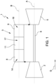
- reference numeral 1 indicates a gas turbine assembly.
- the gas turbine assembly 1 comprises a compressor 2, a sequential combustor assembly 3 and a turbine 5.
- the compressor 2 and the turbine 5 extend along a main axis A.
- an airflow compressed in the compressor 2 is mixed with fuel and is burned in the sequential combustor assembly 3.
- the burned mixture is then expanded in the turbine 5 and converted in mechanical power by a shaft 6, which is connected to an alternator (not shown).
- the sequential combustor assembly 3 comprises a first-stage combustor 8 and a second-stage combustor 9 sequentially arranged along the gas flow direction G.
- the second stage combustor 9 is arranged downstream the first stage combustor 8 along the gas flow direction G.
- a mixer 11 is arranged between the first stage combustor 8 and the second stage combustor 9 .
- the first stage combustor 8 defines a first combustion chamber 14, the second stage combustor 9 defines a second combustion chamber 16, while the mixer 11 defines a mixing chamber 17.
- the first combustion chamber 14, the second combustion chamber 16 and the mixing chamber 17 are in fluidic communication and are defined by a liner 18 (see figure 2 wherein the liner 18 is partially visible), which extends along a longitudinal axis B.
- a supply assembly 20 is arranged in the second combustion chamber 16 of the second stage combustor 9 .
- the supply assembly 20 comprises a central body 21 provided with a plurality of fingers 22 (schematically represented also in figure 3 ).
- the fingers 22 are preferably defined by streamlined bodies, each of which is provided with a plurality of nozzles 24 and is supplied with air and at least one fuel.
- the second stage combustor 9 comprises at least one damper 30.
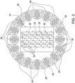
- the second stage combustor 9 comprises a plurality of dampers 30 (in the example here illustrated the dampers are sixteen). Using more than one damper 30 gives the possibility to increase the damping amplitude.
- the dampers 30 are arranged about the central body 21 of the supply assembly 20. More preferably, the dampers 30 are evenly distributed about the central body 21.
- the dampers 30 are preferably coupled to a panel 26 surrounding the central body 21 of the supply assembly 20.
- the panel 26 is also provided with a plurality of cooling holes 25 evenly distributed along the panel 26.
- damper 30 can be arranged also in another portion of the combustor assembly 3.
- damper 30 can be coupled to the liner 18, preferably to the portion of the liner 18 facing the second combustion chamber 16. Damper 30 can also be arranged so as to face into the first combustion chamber 14.
- the damper 30 extends along an extension axis C and comprises a first damper body 31 having a first cavity defining a first damping volume 32, a second damper body 34 having a second cavity defining a second damping volume 35, a perforated connecting plate 36 connecting the first damping volume 32 and the second damping volume 35 and at least one perforated end plate 38.
- the perforated end plate 38 is configured to connect the first damping volume 32 with the outside of the damper 30 which is in fluidic communication with the first combustion chambers 14 and/or the second combustion chamber 16 of the combustor assembly 3.
- the first damping volume 32 and the second damping volume 35 are interconnected in fluidic communication by the perforated connecting plate 36.
- first damping volume 32 and the second damping volume 35 are interconnected in series.
- the first damping volume 32 and the second damping volume 35 are interconnected in parallel.
- the second damper body 34 is provided with at least one inlet 40 configured to be in fluidic communication with at least one source of air.
- the inlet 40 is connected to a plenum (not visible in the attached figures) receiving air from the compressor 2.
- the second damper body 34 is provided with two or more inlets 40 arranged at the bottom of the second cavity.
- the air enters through the inlets 40, flows into the second damping volume 35, passes through the perforated connecting plate 36, flows into the first damping volume 32 and exits through the perforated end plate 38 into the first combustion chambers 14 and/or the second combustion chamber 16 of the combustor assembly 3.
- the air contributes to cool the first damper body 31 and the second damper body 34 and avoid hot gas ingestion, which would de-tune the first damper body 31 and the second damper body 34 and could cause damages to the first damping body 31 and the second damper body 34.
- the inlets 40 are arranged on opposite sides of the second damper body 34.
- the perforated connecting plate 36 and the perforated end plate 38 have a similar structure. Both the perforated connecting plate 36 and the perforated end plate 38 are provided with a plurality of openings 42.
- the openings 42 have a circular shape.
- shape of the openings can be different, for example polygonal or oval or oblong, etc.
- the perforated connecting plate 36 and the perforated end plate 38 are both designed so as to operate in a low Strouhal regime.
- the Strouhal regime is defined by the value of the Strouhal number.
- the openings 42 of the perforated connecting plate 36 and of the perforated end plate 38 are dimensioned according to the following condition: wherein
- the perforated end plate 38 faces directly the first combustion chambers 14 and/or the second combustion chamber 16 and therefore is designed to resist to high temperatures. Thickness and material of the perforated end plate 38 are therefore chosen to guarantee high reliability.
- the perforated connecting plate 36 is subjected to high temperatures too although in a lesser way than the perforated end plate 38.
- the perforated connecting plate 36 and the perforated end plate 38 are made of the same material.
- the perforated connecting plate 36 and the perforated end plate 38 are made with a high temperature resistant material, for example a superalloy as Hastelloy X.
- the perforated connecting plate 36 and the perforated end plate 38 have a different thickness.
- the perforated end plate 38 is preferably thicker than perforated connecting plate 36 as facing the combustion chamber.
- the openings 42 are substantially arranged according to a cross mesh pattern.
- the openings 42 can be substantially arranged according to a square mesh pattern or according to a rectangular mesh pattern or other patterns.
- the mesh pattern of the perforated connecting plate 36 is identical to the mesh pattern of the perforated end plate 38. In this way the openings 42 of the perforated connecting plate 36 are aligned with the openings 42 of the perforated end plate 38.
- the mesh pattern of the perforated connecting plate 36 and of the perforated end plate 38 can be different from each other and the openings 42 of the perforated connecting plate 36 can be misaligned with the openings 42 of the perforated end plate 38.
- Such a solution is useful when the distance between the perforated connecting plate 36 and the perforated end plate 38 is lower than a threshold.
- the openings 42 of the perforated connecting plate 36 are misaligned with openings 42 of the perforated end plate 38 when the length L1 of the first cavity is lower than a threshold.
- the openings 42 of the perforated connecting plate 36 and of the perforated end plate 38 are arranged so as to extend perpendicularly to the plane a 1 a 2 along which the respective perforated connecting plate 36 or the perforated end plate 38 extends.
- the first cavity of the first damper body 31 and the second cavity of the second damper body 34 are dimensioned so as to give to the damper 30 a desired damping effect.
- the first cavity of the first damper body 31 and the second cavity of the second damper body 34 are cylindrical. According to variants not shown, the first cavity of the first damper body 31 and the second cavity of the second damper body 34 can be also prismatic or can have a shape adjusted on the basis of the space available in the combustor assembly 3.
- the first cavity of the first damper body 31 and of the second cavity of the second damper body 34 are designed so as to be a quarter wave tube.
- the dimensioning can be made according to a derivation of the above quarter wave tube formula.
- first cavity of the first damper body 31 and of the second cavity of the second damper body 34 are designed so as to be a Helmholtz resonator.
- the dimensioning can be made according to a derivation of the above Helmholtz formula.
- the dimensioning is preferably made with the quarter wave formula as it is independent from the features of the respective perforated plates.
- the dimensioning is made using the Helmholtz formula.
- the first cavity of the first damper body 31 is dimensioned to damp a first frequency while the second cavity of the second damper body 34 is dimensioned to damp a second frequency different from the first frequency.
- the damper 30 so dimensioned and designed is able to dampen a broad band of frequencies.
- the damper 30, in fact, is able to damp at least three frequencies: the one depending from the dimensions of the first cavity, the one depending from the dimensions of the second cavity and the one depending from the dimensions of the first cavity plus the second cavity.
- the reflection coefficient in fact, is mainly driven by the eigenmode of the two cavities together (i.e. L2+L1), while the response is modulated by the dimensions of each cavity L1 and L2.
- the ratio is defined as "substantially integer”.
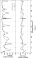
- the trends shown in figure 5 are relating to values of the lengths L1 and L2, which are inverted.
- dotted line represents a solution wherein L2>L1
- continuous line represents a solution wherein the same lengths are inverted (i.e. L2 ⁇ L1).
- the concordance of modes is between the eigenmode of the first cavity L1 and of the second cavity L2.
- the damping and the reflection coefficient is mainly driven by the eigenmode of the 2 cavities together (i.e. L2+L1), it is when the eigenmode of the first cavity or of the second cavity has the same frequency as the eigenmode of the two cavities together (i.e. L2+L1) that the damping gets the best increase.
Landscapes
- Engineering & Computer Science (AREA)
- Chemical & Material Sciences (AREA)
- Combustion & Propulsion (AREA)
- Mechanical Engineering (AREA)
- General Engineering & Computer Science (AREA)
- Soundproofing, Sound Blocking, And Sound Damping (AREA)
Claims (13)
- Brennkammeranordnung für eine Gasturbinenanordnung (1), die mindestens eine Verbrennungskammer (14; 16) und mindestens einen Dämpfer (30) umfasst; wobei der Dämpfer umfasst:- mindestens zwei Dämpfungsvolumina (32, 35), die durch entsprechende Dämpfungskörper (31, 34) definiert sind; wobei die Dämpfungsvolumina (32, 35) in Fluidverbindung miteinander verbunden sind;- mindestens eine perforierte Verbindungsplatte (36), welche die zwei Dämpfungsvolumina (32, 35) verbindet;- mindestens eine perforierte Endplatte (38), die mindestens eines der zwei Dämpfungsvolumina (32, 35) mit einer Verbrennungskammer (16; 14) der Brennkammeranordnung (3) verbindet;wobei die perforierte Verbindungsplatte (36) und die perforierte Endplatte (38) mit einer Vielzahl von Öffnungen (42) versehen sind, dadurch gekennzeichnet, dass die Öffnungen (42) bemessen sind, um in einem Betriebszustand mit niedriger Strouhal-Zahl gemäß der folgenden Formel betrieben zu werden:
 • ω die Winkelfrequenz ist, die mit der zu dämpfenden Frequenz gemäß der folgenden Beziehung ω=2πf korreliert ist;• RH der äquivalente Radius von einer der Öffnungen (42) ist;• Ub die Geschwindigkeit der Strömung durch eine der Öffnungen (42) ist.
 - Brennkammeranordnung nach Anspruch 1, wobei mindestens einer der Dämpfungskörper (31, 34) mindestens einen Einlass (40) umfasst, der dazu ausgestaltet ist, in Fluidverbindung mit mindestens einer Luftquelle zu sein.
- Brennkammeranordnung nach einem der vorhergehenden Ansprüche, wobei die mindestens zwei Dämpfungsvolumina (32, 35) parallel miteinander verbunden sind.
- Brennkammeranordnung nach einem der vorhergehenden Ansprüche, wobei die mindestens zwei Dämpfungsvolumina (32, 35) in Reihe miteinander verbunden sind.
- Brennkammeranordnung nach einem der vorhergehenden Ansprüche, wobei mindestens eines der Dämpfungsvolumina (32, 35) ein Viertelwellenrohr ist.
- Brennkammeranordnung nach einem der vorhergehenden Ansprüche, wobei mindestens eines der Dämpfungsvolumina (32, 35) ein Helmholtz-Resonator ist.
- Brennkammeranordnung nach einem der vorhergehenden Ansprüche, die einen ersten Dämpfungskörper (31; 34), der sich entlang einer Erstreckungsachse (C) erstreckt und eine erste axiale Länge (L1; L2) aufweist, und einen zweiten Dämpfungskörper (34; 31) umfasst, der sich entlang einer Erstreckungsachse (C) erstreckt und eine zweite axiale Länge (L2; L1) aufweist; wobei das Verhältnis (L1/L2; L2/L1) zwischen der größeren axialen Länge (L1, L2; L2, L1) von der ersten axialen Länge (L1; L2) und der zweiten axialen Länge (L2; L1) und der kleineren von der ersten axialen Länge (L1; L2) und der zweiten axialen Länge (L2; L1) im Wesentlichen ganzzahlig, vorzugsweise geradzahlig ist.
- Gasturbinenanordnung, die einen Verdichter (2), eine Gasturbine (5) und eine Brennkammeranordnung (3) nach einem der vorhergehenden Ansprüche umfasst.
- Verfahren zur Herstellung einer Brennkammeranordnung (3) einer Gasturbinenanordnung (1) nach einem der Ansprüche 1 bis 7, wobei das Verfahren zur Herstellung des Dämpfers die folgenden Schritte umfasst:- Bereitstellen mindestens zweier Dämpfungsvolumina (32, 35), die durch entsprechende Dämpfungskörper (31, 34) definiert sind, die sich entlang einer entsprechenden Erstreckungsachse (C) erstrecken; wobei die Dämpfungsvolumina (32, 35) in Fluidverbindung miteinander verbunden sind;- Bereitstellen mindestens einer perforierten Verbindungsplatte (36), die eine Vielzahl von Öffnungen (42) aufweist und die zwei Dämpfungsvolumina (32, 35) verbindet;- Bereitstellen mindestens einer perforierten Endplatte (38), die eine Vielzahl von Öffnungen (42) aufweist und dazu ausgestaltet ist, mindestens eines der zwei Dämpfungsvolumina (32, 35) mit einer Verbrennungskammer (16; 14) der Brennkammeranordnung (3) zu verbinden;wobei der Schritt des Bereitstellens mindestens einer perforierten Verbindungsplatte (36) das Bemessen der Öffnungen (42) umfasst, um in einem Betriebszustand mit niedriger Strouhal-Zahl gemäß der folgenden Formel betrieben zu werden:
 ω die Winkelfrequenz ist, die mit der zu dämpfenden Frequenz gemäß der folgenden Beziehung ω=2πf korreliert ist;RH der äquivalente Radius von einer der Öffnungen (42) ist;Ub die Geschwindigkeit der Strömung durch eine der Öffnungen (42) ist.
 - Verfahren nach Anspruch 9, wobei der Schritt des Bereitstellens mindestens zweier Dämpfungsvolumina (32, 35) das Bemessen eines ersten Hohlraums eines ersten Dämpferkörpers (31) zum Dämpfen einer ersten Frequenz und das Bemessen eines zweiten Hohlraums eines zweiten Dämpferkörpers (34) zum Dämpfen einer zweiten Frequenz umfasst, die sich von der ersten Frequenz unterscheidet.
- Verfahren nach Anspruch 9 oder 10, wobei der Schritt des Bereitstellens mindestens zweier Dämpfungsvolumina (32, 35) das Bemessen mindestens eines der zwei Dämpfungsvolumina (32, 35) als ein Viertelwellenrohr umfasst.
- Verfahren nach einem der Ansprüche 9 bis 11, wobei der Schritt des Bereitstellens mindestens zweier Dämpfungsvolumina (32, 35) das Bemessen mindestens eines der zwei Dämpfungsvolumina (32, 35) als ein Helmholtz-Resonator umfasst.
- Verfahren nach einem der Ansprüche 9 bis 12, wobei der Schritt des Bereitstellens mindestens zweier Dämpfungsvolumina (32, 35) das Bemessen eines ersten Hohlraums eines ersten Dämpferkörpers (31; 34), der eine erste axiale Länge (L1; L2) aufweist, und eines zweiten Hohlraums eines zweiten Dämpfungskörpers (34; 31), der eine zweite axiale Länge (L2; L1) aufweist, umfasst, derart dass das Verhältnis (L1/L2; L2/L1) zwischen der größeren axialen Länge (L1, L2; L2, L1) von der ersten axialen Länge (L1; L2) und der zweiten axialen Länge (L2; L1) und der kleineren von der ersten axialen Länge (L1; L2) und der zweiten axialen Länge (L2; L1) im Wesentlichen ganzzahlig, vorzugsweise geradzahlig ist.
Priority Applications (2)
| Application Number | Priority Date | Filing Date | Title |
|---|---|---|---|
| EP19183732.7A EP3760925B1 (de) | 2019-07-01 | 2019-07-01 | Brennkammeranordnung einer gasturbinenbaugruppe mit dämpfer und verfahren zur herstellung |
| CN202010619065.XA CN112178695B (zh) | 2019-07-01 | 2020-07-01 | 阻尼器、包括阻尼器的燃烧器组件及制造阻尼器的方法 |
Applications Claiming Priority (1)
| Application Number | Priority Date | Filing Date | Title |
|---|---|---|---|
| EP19183732.7A EP3760925B1 (de) | 2019-07-01 | 2019-07-01 | Brennkammeranordnung einer gasturbinenbaugruppe mit dämpfer und verfahren zur herstellung |
Publications (2)
| Publication Number | Publication Date |
|---|---|
| EP3760925A1 EP3760925A1 (de) | 2021-01-06 |
| EP3760925B1 true EP3760925B1 (de) | 2024-12-18 |
Family
ID=67139639
Family Applications (1)
| Application Number | Title | Priority Date | Filing Date |
|---|---|---|---|
| EP19183732.7A Active EP3760925B1 (de) | 2019-07-01 | 2019-07-01 | Brennkammeranordnung einer gasturbinenbaugruppe mit dämpfer und verfahren zur herstellung |
Country Status (2)
| Country | Link |
|---|---|
| EP (1) | EP3760925B1 (de) |
| CN (1) | CN112178695B (de) |
Families Citing this family (3)
| Publication number | Priority date | Publication date | Assignee | Title |
|---|---|---|---|---|
| CN115682033B (zh) * | 2021-07-28 | 2024-09-24 | 北京航空航天大学 | 防振燃烧室以及燃烧室防振方法 |
| CN116293795B (zh) * | 2021-12-06 | 2025-05-16 | 通用电气阿维奥有限责任公司 | 用于燃气涡轮燃烧器应用的圆顶集成声学阻尼器 |
| CN117917528A (zh) * | 2022-10-20 | 2024-04-23 | 通用电气公司 | 用于燃烧器的整流罩阻尼器 |
Family Cites Families (12)
| Publication number | Priority date | Publication date | Assignee | Title |
|---|---|---|---|---|
| DE2728778B2 (de) * | 1977-06-25 | 1979-08-30 | Bayer Ag, 5090 Leverkusen | Verfahren zur Geräuschminderung bei der Drosselung von Dampf- und Gasstromen |
| DE19640980B4 (de) * | 1996-10-04 | 2008-06-19 | Alstom | Vorrichtung zur Dämpfung von thermoakustischen Schwingungen in einer Brennkammer |
| JP4592513B2 (ja) * | 2004-09-30 | 2010-12-01 | 三菱重工業株式会社 | ガスタービン制御装置、及びガスタービンシステム |
| US8789372B2 (en) * | 2009-07-08 | 2014-07-29 | General Electric Company | Injector with integrated resonator |
| EP2385303A1 (de) * | 2010-05-03 | 2011-11-09 | Alstom Technology Ltd | Verbrennungsvorrichtung für eine Gasturbine |
| EP2397759A1 (de) * | 2010-06-16 | 2011-12-21 | Alstom Technology Ltd | Dämpfungsanordnung |
| US20120180500A1 (en) * | 2011-01-13 | 2012-07-19 | General Electric Company | System for damping vibration in a gas turbine engine |
| WO2013144070A1 (en) * | 2012-03-30 | 2013-10-03 | Alstom Technology Ltd | Combustion chamber seal segments equipped with damping devices |
| US10088165B2 (en) * | 2015-04-07 | 2018-10-02 | General Electric Company | System and method for tuning resonators |
| EP2860451A1 (de) * | 2013-10-11 | 2015-04-15 | Alstom Technology Ltd | Brennkammer einer Gasturbine mit verbesserter Schalldämpfung |
| EP3153777B1 (de) * | 2015-10-05 | 2021-03-03 | Ansaldo Energia Switzerland AG | Dämpferanordnung für eine brennkammer |
| US20180313540A1 (en) * | 2017-05-01 | 2018-11-01 | General Electric Company | Acoustic Damper for Gas Turbine Engine Combustors |
-
2019
- 2019-07-01 EP EP19183732.7A patent/EP3760925B1/de active Active
-
2020
- 2020-07-01 CN CN202010619065.XA patent/CN112178695B/zh active Active
Also Published As
| Publication number | Publication date |
|---|---|
| CN112178695A (zh) | 2021-01-05 |
| CN112178695B (zh) | 2024-07-26 |
| EP3760925A1 (de) | 2021-01-06 |
Similar Documents
| Publication | Publication Date | Title |
|---|---|---|
| US8733496B2 (en) | Acoustic damper, combustor, and gas turbine | |
| US10094568B2 (en) | Combustor dynamics mitigation | |
| CN102889613B (zh) | 用于对涡轮机燃烧器中的振荡进行阻尼的系统 | |
| CA2384336C (en) | A combustion chamber | |
| US8516819B2 (en) | Forward-section resonator for high frequency dynamic damping | |
| CN101680663B (zh) | 具有亥姆霍兹共振器的涡轮发动机燃料喷射器 | |
| US9217373B2 (en) | Fuel nozzle for reducing modal coupling of combustion dynamics | |
| KR101201559B1 (ko) | 감쇠 장치 및 가스 터빈 연소기 | |
| EP3760925B1 (de) | Brennkammeranordnung einer gasturbinenbaugruppe mit dämpfer und verfahren zur herstellung | |
| CN103842727A (zh) | 用于衰减低频动力的燃烧器帽 | |
| US8631654B2 (en) | Burner system and method for damping such a burner system | |
| JP2010271034A (ja) | 共鳴スワーラ | |
| US20140013754A1 (en) | Power augmentation system with dynamics damping | |
| EP3974723B1 (de) | Gasturbine für kraftwerk mit einer dämpfungsvorrichtung | |
| EP3663548B1 (de) | Dämpfer für eine brennkammeranordnung eines gasturbinenkraftwerks und brennkammeranordnung mit dem dämpfer | |
| JP2004183946A (ja) | ガスタービン燃焼器、及びこれを備えたガスタービン |
Legal Events
| Date | Code | Title | Description |
|---|---|---|---|
| PUAI | Public reference made under article 153(3) epc to a published international application that has entered the european phase |
Free format text: ORIGINAL CODE: 0009012 |
|
| STAA | Information on the status of an ep patent application or granted ep patent |
Free format text: STATUS: THE APPLICATION HAS BEEN PUBLISHED |
|
| AK | Designated contracting states |
Kind code of ref document: A1 Designated state(s): AL AT BE BG CH CY CZ DE DK EE ES FI FR GB GR HR HU IE IS IT LI LT LU LV MC MK MT NL NO PL PT RO RS SE SI SK SM TR |
|
| AX | Request for extension of the european patent |
Extension state: BA ME |
|
| STAA | Information on the status of an ep patent application or granted ep patent |
Free format text: STATUS: REQUEST FOR EXAMINATION WAS MADE |
|
| 17P | Request for examination filed |
Effective date: 20210705 |
|
| RBV | Designated contracting states (corrected) |
Designated state(s): AL AT BE BG CH CY CZ DE DK EE ES FI FR GB GR HR HU IE IS IT LI LT LU LV MC MK MT NL NO PL PT RO RS SE SI SK SM TR |
|
| STAA | Information on the status of an ep patent application or granted ep patent |
Free format text: STATUS: EXAMINATION IS IN PROGRESS |
|
| 17Q | First examination report despatched |
Effective date: 20221004 |
|
| P01 | Opt-out of the competence of the unified patent court (upc) registered |
Effective date: 20240430 |
|
| GRAP | Despatch of communication of intention to grant a patent |
Free format text: ORIGINAL CODE: EPIDOSNIGR1 |
|
| STAA | Information on the status of an ep patent application or granted ep patent |
Free format text: STATUS: GRANT OF PATENT IS INTENDED |
|
| INTG | Intention to grant announced |
Effective date: 20240716 |
|
| GRAS | Grant fee paid |
Free format text: ORIGINAL CODE: EPIDOSNIGR3 |
|
| GRAA | (expected) grant |
Free format text: ORIGINAL CODE: 0009210 |
|
| STAA | Information on the status of an ep patent application or granted ep patent |
Free format text: STATUS: THE PATENT HAS BEEN GRANTED |
|
| AK | Designated contracting states |
Kind code of ref document: B1 Designated state(s): AL AT BE BG CH CY CZ DE DK EE ES FI FR GB GR HR HU IE IS IT LI LT LU LV MC MK MT NL NO PL PT RO RS SE SI SK SM TR |
|
| REG | Reference to a national code |
Ref country code: CH Ref legal event code: EP |
|
| REG | Reference to a national code |
Ref country code: DE Ref legal event code: R096 Ref document number: 602019063572 Country of ref document: DE |
|
| REG | Reference to a national code |
Ref country code: IE Ref legal event code: FG4D |
|
| REG | Reference to a national code |
Ref country code: LT Ref legal event code: MG9D |
|
| PG25 | Lapsed in a contracting state [announced via postgrant information from national office to epo] |
Ref country code: HR Free format text: LAPSE BECAUSE OF FAILURE TO SUBMIT A TRANSLATION OF THE DESCRIPTION OR TO PAY THE FEE WITHIN THE PRESCRIBED TIME-LIMIT Effective date: 20241218 |
|
| PG25 | Lapsed in a contracting state [announced via postgrant information from national office to epo] |
Ref country code: FI Free format text: LAPSE BECAUSE OF FAILURE TO SUBMIT A TRANSLATION OF THE DESCRIPTION OR TO PAY THE FEE WITHIN THE PRESCRIBED TIME-LIMIT Effective date: 20241218 |
|
| PG25 | Lapsed in a contracting state [announced via postgrant information from national office to epo] |
Ref country code: BG Free format text: LAPSE BECAUSE OF FAILURE TO SUBMIT A TRANSLATION OF THE DESCRIPTION OR TO PAY THE FEE WITHIN THE PRESCRIBED TIME-LIMIT Effective date: 20241218 |
|
| PG25 | Lapsed in a contracting state [announced via postgrant information from national office to epo] |
Ref country code: NO Free format text: LAPSE BECAUSE OF FAILURE TO SUBMIT A TRANSLATION OF THE DESCRIPTION OR TO PAY THE FEE WITHIN THE PRESCRIBED TIME-LIMIT Effective date: 20250318 |
|
| REG | Reference to a national code |
Ref country code: NL Ref legal event code: MP Effective date: 20241218 |
|
| PG25 | Lapsed in a contracting state [announced via postgrant information from national office to epo] |
Ref country code: LV Free format text: LAPSE BECAUSE OF FAILURE TO SUBMIT A TRANSLATION OF THE DESCRIPTION OR TO PAY THE FEE WITHIN THE PRESCRIBED TIME-LIMIT Effective date: 20241218 Ref country code: GR Free format text: LAPSE BECAUSE OF FAILURE TO SUBMIT A TRANSLATION OF THE DESCRIPTION OR TO PAY THE FEE WITHIN THE PRESCRIBED TIME-LIMIT Effective date: 20250319 |
|
| PG25 | Lapsed in a contracting state [announced via postgrant information from national office to epo] |
Ref country code: RS Free format text: LAPSE BECAUSE OF FAILURE TO SUBMIT A TRANSLATION OF THE DESCRIPTION OR TO PAY THE FEE WITHIN THE PRESCRIBED TIME-LIMIT Effective date: 20250318 |
|
| PG25 | Lapsed in a contracting state [announced via postgrant information from national office to epo] |
Ref country code: NL Free format text: LAPSE BECAUSE OF FAILURE TO SUBMIT A TRANSLATION OF THE DESCRIPTION OR TO PAY THE FEE WITHIN THE PRESCRIBED TIME-LIMIT Effective date: 20241218 |
|
| REG | Reference to a national code |
Ref country code: AT Ref legal event code: MK05 Ref document number: 1752495 Country of ref document: AT Kind code of ref document: T Effective date: 20241218 |
|
| PG25 | Lapsed in a contracting state [announced via postgrant information from national office to epo] |
Ref country code: SM Free format text: LAPSE BECAUSE OF FAILURE TO SUBMIT A TRANSLATION OF THE DESCRIPTION OR TO PAY THE FEE WITHIN THE PRESCRIBED TIME-LIMIT Effective date: 20241218 |
|
| PG25 | Lapsed in a contracting state [announced via postgrant information from national office to epo] |
Ref country code: PL Free format text: LAPSE BECAUSE OF FAILURE TO SUBMIT A TRANSLATION OF THE DESCRIPTION OR TO PAY THE FEE WITHIN THE PRESCRIBED TIME-LIMIT Effective date: 20241218 |
|
| PG25 | Lapsed in a contracting state [announced via postgrant information from national office to epo] |
Ref country code: ES Free format text: LAPSE BECAUSE OF FAILURE TO SUBMIT A TRANSLATION OF THE DESCRIPTION OR TO PAY THE FEE WITHIN THE PRESCRIBED TIME-LIMIT Effective date: 20241218 |
|
| PG25 | Lapsed in a contracting state [announced via postgrant information from national office to epo] |
Ref country code: IS Free format text: LAPSE BECAUSE OF FAILURE TO SUBMIT A TRANSLATION OF THE DESCRIPTION OR TO PAY THE FEE WITHIN THE PRESCRIBED TIME-LIMIT Effective date: 20250418 |
|
| PG25 | Lapsed in a contracting state [announced via postgrant information from national office to epo] |
Ref country code: PT Free format text: LAPSE BECAUSE OF FAILURE TO SUBMIT A TRANSLATION OF THE DESCRIPTION OR TO PAY THE FEE WITHIN THE PRESCRIBED TIME-LIMIT Effective date: 20250421 |
|
| PG25 | Lapsed in a contracting state [announced via postgrant information from national office to epo] |
Ref country code: EE Free format text: LAPSE BECAUSE OF FAILURE TO SUBMIT A TRANSLATION OF THE DESCRIPTION OR TO PAY THE FEE WITHIN THE PRESCRIBED TIME-LIMIT Effective date: 20241218 |
|
| PG25 | Lapsed in a contracting state [announced via postgrant information from national office to epo] |
Ref country code: RO Free format text: LAPSE BECAUSE OF FAILURE TO SUBMIT A TRANSLATION OF THE DESCRIPTION OR TO PAY THE FEE WITHIN THE PRESCRIBED TIME-LIMIT Effective date: 20241218 Ref country code: AT Free format text: LAPSE BECAUSE OF FAILURE TO SUBMIT A TRANSLATION OF THE DESCRIPTION OR TO PAY THE FEE WITHIN THE PRESCRIBED TIME-LIMIT Effective date: 20241218 |
|
| PG25 | Lapsed in a contracting state [announced via postgrant information from national office to epo] |
Ref country code: SK Free format text: LAPSE BECAUSE OF FAILURE TO SUBMIT A TRANSLATION OF THE DESCRIPTION OR TO PAY THE FEE WITHIN THE PRESCRIBED TIME-LIMIT Effective date: 20241218 |
|
| PG25 | Lapsed in a contracting state [announced via postgrant information from national office to epo] |
Ref country code: CZ Free format text: LAPSE BECAUSE OF FAILURE TO SUBMIT A TRANSLATION OF THE DESCRIPTION OR TO PAY THE FEE WITHIN THE PRESCRIBED TIME-LIMIT Effective date: 20241218 |
|
| PG25 | Lapsed in a contracting state [announced via postgrant information from national office to epo] |
Ref country code: SE Free format text: LAPSE BECAUSE OF FAILURE TO SUBMIT A TRANSLATION OF THE DESCRIPTION OR TO PAY THE FEE WITHIN THE PRESCRIBED TIME-LIMIT Effective date: 20241218 |
|
| REG | Reference to a national code |
Ref country code: DE Ref legal event code: R097 Ref document number: 602019063572 Country of ref document: DE |
|
| PG25 | Lapsed in a contracting state [announced via postgrant information from national office to epo] |
Ref country code: DK Free format text: LAPSE BECAUSE OF FAILURE TO SUBMIT A TRANSLATION OF THE DESCRIPTION OR TO PAY THE FEE WITHIN THE PRESCRIBED TIME-LIMIT Effective date: 20241218 |
|
| PGFP | Annual fee paid to national office [announced via postgrant information from national office to epo] |
Ref country code: DE Payment date: 20250722 Year of fee payment: 7 |
|
| PGFP | Annual fee paid to national office [announced via postgrant information from national office to epo] |
Ref country code: IT Payment date: 20250731 Year of fee payment: 7 |
|
| PLBE | No opposition filed within time limit |
Free format text: ORIGINAL CODE: 0009261 |
|
| STAA | Information on the status of an ep patent application or granted ep patent |
Free format text: STATUS: NO OPPOSITION FILED WITHIN TIME LIMIT |
|
| REG | Reference to a national code |
Ref country code: CH Ref legal event code: L10 Free format text: ST27 STATUS EVENT CODE: U-0-0-L10-L00 (AS PROVIDED BY THE NATIONAL OFFICE) Effective date: 20251029 |
|
| 26N | No opposition filed |
Effective date: 20250919 |
|
| REG | Reference to a national code |
Ref country code: CH Ref legal event code: H13 Free format text: ST27 STATUS EVENT CODE: U-0-0-H10-H13 (AS PROVIDED BY THE NATIONAL OFFICE) Effective date: 20260224 |
|
| PG25 | Lapsed in a contracting state [announced via postgrant information from national office to epo] |
Ref country code: LU Free format text: LAPSE BECAUSE OF NON-PAYMENT OF DUE FEES Effective date: 20250701 |
|
| GBPC | Gb: european patent ceased through non-payment of renewal fee |
Effective date: 20250701 |
|
| REG | Reference to a national code |
Ref country code: BE Ref legal event code: MM Effective date: 20250731 |
|
| PG25 | Lapsed in a contracting state [announced via postgrant information from national office to epo] |
Ref country code: GB Free format text: LAPSE BECAUSE OF NON-PAYMENT OF DUE FEES Effective date: 20250701 |
|
| PG25 | Lapsed in a contracting state [announced via postgrant information from national office to epo] |
Ref country code: BE Free format text: LAPSE BECAUSE OF NON-PAYMENT OF DUE FEES Effective date: 20250731 |
|
| PG25 | Lapsed in a contracting state [announced via postgrant information from national office to epo] |
Ref country code: FR Free format text: LAPSE BECAUSE OF NON-PAYMENT OF DUE FEES Effective date: 20250731 |
|
| PG25 | Lapsed in a contracting state [announced via postgrant information from national office to epo] |
Ref country code: CH Free format text: LAPSE BECAUSE OF NON-PAYMENT OF DUE FEES Effective date: 20250731 |