EP3760930A1 - Heizungsherd - Google Patents
Heizungsherd Download PDFInfo
- Publication number
- EP3760930A1 EP3760930A1 EP19760180.0A EP19760180A EP3760930A1 EP 3760930 A1 EP3760930 A1 EP 3760930A1 EP 19760180 A EP19760180 A EP 19760180A EP 3760930 A1 EP3760930 A1 EP 3760930A1
- Authority
- EP
- European Patent Office
- Prior art keywords
- fan
- outer frame
- door
- disposed
- fan case
- Prior art date
- Legal status (The legal status is an assumption and is not a legal conclusion. Google has not performed a legal analysis and makes no representation as to the accuracy of the status listed.)
- Pending
Links
- 238000010438 heat treatment Methods 0.000 title claims abstract description 84
- 230000002265 prevention Effects 0.000 claims abstract description 38
- 239000002184 metal Substances 0.000 claims description 41
- 238000005192 partition Methods 0.000 claims description 20
- 238000001816 cooling Methods 0.000 description 19
- 238000010586 diagram Methods 0.000 description 4
- 230000000694 effects Effects 0.000 description 3
- 235000013305 food Nutrition 0.000 description 2
- 238000012986 modification Methods 0.000 description 2
- 230000004048 modification Effects 0.000 description 2
- 230000005855 radiation Effects 0.000 description 2
- 229910001335 Galvanized steel Inorganic materials 0.000 description 1
- 240000007594 Oryza sativa Species 0.000 description 1
- 235000007164 Oryza sativa Nutrition 0.000 description 1
- 229910000831 Steel Inorganic materials 0.000 description 1
- 238000010411 cooking Methods 0.000 description 1
- 239000008397 galvanized steel Substances 0.000 description 1
- 239000004973 liquid crystal related substance Substances 0.000 description 1
- 235000009566 rice Nutrition 0.000 description 1
- 239000010959 steel Substances 0.000 description 1
- XLYOFNOQVPJJNP-UHFFFAOYSA-N water Substances O XLYOFNOQVPJJNP-UHFFFAOYSA-N 0.000 description 1
Images






Classifications
-
- H—ELECTRICITY
- H05—ELECTRIC TECHNIQUES NOT OTHERWISE PROVIDED FOR
- H05B—ELECTRIC HEATING; ELECTRIC LIGHT SOURCES NOT OTHERWISE PROVIDED FOR; CIRCUIT ARRANGEMENTS FOR ELECTRIC LIGHT SOURCES, IN GENERAL
- H05B6/00—Heating by electric, magnetic or electromagnetic fields
- H05B6/64—Heating using microwaves
- H05B6/76—Prevention of microwave leakage, e.g. door sealings
- H05B6/763—Microwave radiation seals for doors
-
- F—MECHANICAL ENGINEERING; LIGHTING; HEATING; WEAPONS; BLASTING
- F24—HEATING; RANGES; VENTILATING
- F24C—DOMESTIC STOVES OR RANGES ; DETAILS OF DOMESTIC STOVES OR RANGES, OF GENERAL APPLICATION
- F24C15/00—Details
- F24C15/02—Doors specially adapted for stoves or ranges
-
- F—MECHANICAL ENGINEERING; LIGHTING; HEATING; WEAPONS; BLASTING
- F24—HEATING; RANGES; VENTILATING
- F24C—DOMESTIC STOVES OR RANGES ; DETAILS OF DOMESTIC STOVES OR RANGES, OF GENERAL APPLICATION
- F24C15/00—Details
- F24C15/34—Elements and arrangements for heat storage or insulation
-
- F—MECHANICAL ENGINEERING; LIGHTING; HEATING; WEAPONS; BLASTING
- F24—HEATING; RANGES; VENTILATING
- F24C—DOMESTIC STOVES OR RANGES ; DETAILS OF DOMESTIC STOVES OR RANGES, OF GENERAL APPLICATION
- F24C7/00—Stoves or ranges heated by electric energy
- F24C7/02—Stoves or ranges heated by electric energy using microwaves
-
- H—ELECTRICITY
- H05—ELECTRIC TECHNIQUES NOT OTHERWISE PROVIDED FOR
- H05B—ELECTRIC HEATING; ELECTRIC LIGHT SOURCES NOT OTHERWISE PROVIDED FOR; CIRCUIT ARRANGEMENTS FOR ELECTRIC LIGHT SOURCES, IN GENERAL
- H05B6/00—Heating by electric, magnetic or electromagnetic fields
- H05B6/64—Heating using microwaves
- H05B6/642—Cooling of the microwave components and related air circulation systems
Definitions
- the present disclosure relates to a heating cooker that heats food in a heating chamber.
- a fan is disposed in a flow path of a door through which cooling air flows, thereby improving the cooling capacity.
- the fan includes an air intake port and an exhaust port that are disposed to be substantially vertical in the height direction of the door. The fan draws air from below through the air intake port and discharges air upward from the exhaust port.
- the fan is disposed in the height direction of the door, it is necessary to secure a space in the height direction of the door by the thickness of the fan. Therefore, since the height of the door cannot be shortened, it is difficult to reduce the size of the heating cooker.
- the present disclosure provides a heating cooker that can be reduced in size.
- a heating cooker includes a heating chamber having an opening, and a door that openably covers the opening of the heating chamber.
- the door includes an outer frame, a radio wave leakage prevention plate attached to a rear side of the outer frame, an inner frame that sandwiches the radio wave leakage prevention plate between the inner frame and the outer frame, an air intake port provided at a lower portion of the outer frame to take in external air, a board attached to the outer frame, a fan attached to the outer frame, and a first air passage extending from the fan to the board.
- the fan is disposed forward of the radio wave leakage prevention plate, and at least a part of the fan is disposed inside the radio wave leakage prevention plate in a rear view.
- An air intake port of the fan is disposed in a direction in which the intake direction intersects with the air intake port of the outer frame in a front-rear direction of the door in an upright state. Furthermore, the exhaust port of the fan is disposed in a direction in which the discharge direction intersects the intake direction of the fan.
- FIGS. 1 and 2 a heating cooker according to the exemplary embodiment of the present disclosure will be described with reference to FIGS. 1 and 2 .
- FIG. 1 is a front view of heating cooker 1 according to the exemplary embodiment.
- FIG. 2 is a front perspective view of heating cooker 1 with door 7 opened.
- the X direction is described as the longitudinal direction (width direction or left and right direction) of heating cooker 1
- the Y direction is described as the front-rear direction thereof
- the Z direction is described as the height direction thereof.
- the height refers to a distance from the mounting surface of heating cooker 1.
- heating cooker 1 includes housing 3, heating chamber 5 disposed in housing 3, and door 7 and the like.
- Door 7 includes outer frame 13 that openably covers opening 3b opened in front frame 3a serving as a front surface of housing 3.
- Heating chamber 5 is configured by a space formed by being surrounded by upper wall 5a disposed at the upper portion, side walls 5b and 5c disposed at both sides, a rear wall (not shown) disposed at the rear portion, and bottom wall 5e disposed at the lower portion.
- Heating chamber 5 includes a microwave radiation port (not shown) for radiating microwaves.
- Heating cooker 1 is configured to dielectrically heat the object to be heated (food) placed in heating chamber 5 by the microwave radiated from the microwave radiation port.
- heating chamber 5 includes a steam outlet (not shown) in the upper portion. Thereby, the steam generated by a steam generator (not shown) is supplied into heating chamber 5.
- Door 7 includes a rotation center in the horizontal direction on the lower side of opening 3b. Thereby, door 7 is openably attached to housing 3 with the rotation center as the rotation axis.
- Door 7 includes handle 7a mounted on the upper portion of outer frame 13. When the user pulls handle 7a forward and downward, door 7 is rotated so as to be in a horizontal state, and heating chamber 5 is opened. In addition, heating chamber 5 is closed by the user rotating door 7 so as to be in the vertical state.
- Outer frame 13 of door 7 includes display unit 9, operation unit 11, and the like disposed near the other side (right side) in the longitudinal direction (X direction) in a front view.
- Display unit 9 is configured by, for example, a liquid crystal screen, and displays a menu screen and the like.
- Operation unit 11 includes functions such as a push button, a dial, and the like. The user can set various cooking instructions and the like in heating cooker 1 using operation unit 11. Note that, hereinafter, one side in the longitudinal direction will be described as a left side, and the other side will be described as a right side in the front view of heating cooker 1.
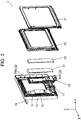
- FIG. 3 is an exploded perspective view of door 7. Note that in the following, when the positional relationship of the components of door 7 is described, the positional relationship with door 7 disposed upright in the Z direction will be described.
- outer frame 13, display unit 9, board 15, fan 17, fan case 19, first metal plate 21 and second metal plate 23 included in metal plates, radio wave leakage prevention plate 25, inner frame 27, and the like are disposed in stated order from a front side (-Y direction) in door 7. That is, door 7 includes at least the above components.
- Electronic components for controlling display unit 9, operation unit 11, and the like are disposed on board 15. Furthermore, a heating element (not shown) that generates heat during operation is disposed on board 15.
- the heating element is, for example, a microcomputer.
- Fan 17 functions to draw outside air (external air) into door 7 and send it out of door 7. Thereby, board 15 that is heated by the heat from heating chamber 5 is cooled. Fan 17 is disposed forward (-Y direction) from radio wave leakage prevention plate 25.
- Fan case 19 covers the rear of board 15 and fan 17 and forms an air passage through which cooling air generated by fan 17 flows.
- First metal plate 21 is disposed behind board 15 with fan case 19 interposed therebetween. First metal plate 21 functions to block heat transmitted from heating chamber 5 to board 15.
- Second metal plate 23 is disposed so as to cover the rear surface of first metal plate 21. Similarly to first metal plate 21, second metal plate 23 also functions to block heat transmitted from heating chamber 5 to board 15.
- Radio wave leakage prevention plate 25 is configured by a metal plate such as a hot-dip galvanized steel plate or an aluminum-plated steel plate, and is attached to the rear side of outer frame 13. Radio wave leakage prevention plate 25 prevents radio waves (microwaves) from leaking out of the interior of heating chamber 5 to the outside through door 7.
- Inner frame 27 is attached to the rear side of radio wave leakage prevention plate 25. At this time, inner frame 27 is disposed so as to sandwich radio wave leakage prevention plate 25 between inner frame 27 and outer frame 13.
- FIG. 4 is a rear perspective view of door 7 with inner frame 27 removed.
- FIG. 5 is a rear perspective view with radio wave leakage prevention plate 25 removed from door 7 illustrated in FIG. 4 .
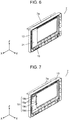
- FIG. 6 is a rear perspective view with second metal plate 23 removed from door 7 illustrated in FIG. 5 .
- Radio wave leakage prevention plate 25 is disposed inside outer frame 13 along the outer edge of outer frame 13 as illustrated in FIG. 4 .
- Second metal plate 23 is disposed on the other side (right side) in the longitudinal direction (X direction) of outer frame 13 as illustrated in FIG. 5 . Second metal plate 23 is located behind board 15 and is disposed between heating chamber 5 and first metal plate 21 in the front-rear direction (Y direction).
- First metal plate 21 is located behind board 15 and is disposed between second metal plate 23 and fan case 19 in the front-rear direction (Y direction) as illustrated in FIG. 6 .
- FIG. 7 is a rear perspective view with first metal plate 21 removed from door 7 illustrated in FIG. 6 .
- FIG. 8 is a rear view with first metal plate 21 removed from door 7 illustrated in FIG. 6 .
- fan case 19 is located behind board 15 and is disposed between board 15 and second metal plate 23 in the front-rear direction (Y direction).
- Fan case 19 includes hole 19a, which is a through-hole, near the inner side (left side) on the upper side.
- Hole 19a is formed, for example, as a long hole extending in the vertical direction (Z direction).
- Two holes 19a are formed in fan case 19 side by side in the vertical direction.
- Behind the hole 19a for example, L-shaped cover 19c that opens to the front side and the outside (right side) in the longitudinal direction of door 7 is attached to fan case 19.
- Cover 19c functions to change the direction of the cooling air flowing backward from board 15 so as to flow outward on the rear surface of fan case 19.
- fan case 19 has a plurality of upper holes 19b formed in the vicinity of the upper portion along the longitudinal direction of door 7. Thereby, the cooling air flowing from the lower end to the upper end of board 15 flows into the rear surface of fan case 19 through upper holes 19b.
- wall 19d protruding rearward is provided near the outside (right side) of the lower side of fan case 19 on the other side (right side) in the longitudinal direction (X direction) of door 7.
- wall 19d protruding rearward is provided near the outside (right side) of the lower side of fan case 19 on the other side (right side) in the longitudinal direction (X direction) of door 7.
- FIG. 9 is a rear perspective view with fan case 19 removed from door 7 illustrated in FIG. 7 .
- FIG. 10 is a rear view with fan case 19 removed from door 7 illustrated in FIG. 7 .
- outer frame 13 of door 7 has air intake port 13a formed at a lower portion on the other side (right side) in the longitudinal direction (X direction) to take in external air. Furthermore, board 15 is attached to outer frame 13 together with display unit 9. In addition, fan 17 is provided near the lower portion of outer frame 13 on the other side in the longitudinal direction and above air intake port 13a.
- FIG. 11 is an enlarged view around fan 17 illustrated in FIG. 10 .
- fan 17 has air intake port 17a and exhaust port 17b.
- the opening of air intake port 17a is provided in the front-rear direction (Y direction) of door 7.
- the opening of exhaust port 17b of fan 17 is provided toward the upper direction (Z direction) of door 7.
- air intake port 17a of fan 17 that takes in external air is disposed such that the intake direction is the front-rear direction (Y direction) of door 7 in the upright state, that is, the direction intersecting air intake port 13a of outer frame 13 (see FIG. 13 ).
- the direction in which fan 17 takes in and the direction in which air intake port 13a intersects may be a right angle.
- exhaust port 17b of fan 17 is disposed such that the discharge direction is a direction intersecting the intake direction of air intake port 17a.
- a direction intersecting between the discharge direction of air intake port 17a of fan 17 and the intake direction of exhaust port 17b of fan 17 may be a right angle. Therefore, the axis of rotation of the blade of fan 17 is disposed along the front-rear direction (Y direction).
- a sirocco fan is exemplified as fan 17.
- outer frame 13 includes first partition wall 13c and second partition wall 13d extending rearward (Y direction) from the rear surface of outer frame 13.
- Groove 13b is formed by first partition wall 13c, second partition wall 13d, and rear wall 13e that is a part of the rear surface of outer frame 13.
- Groove 13b extends upward from exhaust port 17b of fan 17.
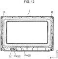
- radio wave leakage prevention plate 25 and fan 17 will be described with reference to FIG. 12 .
- FIG. 12 is a diagram illustrating the positional relationship between radio wave leakage prevention plate 25 and fan 17 of door 7 of heating cooker 1.
- fan 17 is disposed inside radio wave leakage prevention plate 25 in a rear view and is covered with radio wave leakage prevention plate 25.
- fan 17 is disposed such that, for example, the upper portion including exhaust port 17b and the vicinity of the central part are crawled inside radio wave leakage prevention plate 25.
- the lower portion of fan 17 is disposed so as to protrude downward from lower edge 25a of radio wave leakage prevention plate 25. With this disposition, it is not necessary to dispose the air intake port and the exhaust port in the vertical direction unlike the conventional fan configuration, so that the length (dimension) of door 7 in the height direction can be reduced.
- FIG. 13 is a view inside door 7 as viewed from a longitudinal cross section around fan 17.
- FIG. 14 is a front perspective view of fan 17, fan case 19, and board 15.
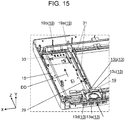
- FIG. 15 is a diagram illustrating air passages. Note that in FIG. 15 , fan case 19 is illustrated by a broken line, and is illustrated with the inside seen through.
- fan case 19 further includes outer wall 19e, partition wall 19g, hole 19h, and front wall 19k.
- Outer wall 19e extends forward (-Y direction) from the inner (left side) end of the front surface of fan case 19.
- Partition wall 19g extends outside (to the right of) outer wall 19e and forward (-Y direction) parallel to outer wall 19e.
- Hole 19h is opened in partition wall 19g at a position corresponding to a branch point between first air passage 29 and second air passage 31 configuring air passages described later.
- Front wall 19k is configured by a part of the front surface of fan case 19.
- Groove 19m is formed by outer wall 19e, partition wall 19g, and front wall 19k described above. Specifically, groove 19m extends upward from exhaust port 17b of fan 17.
- Groove 13b of outer frame 13 and groove 19m of fan case 19 described above are fitted in the front-rear direction (Y direction). Thereby, air passages in which the external air exhausted from exhaust port 17b of fan 17 flows upward (in Z direction) inside fan case 19 are formed.
- hole 19h formed in partition wall 19g of fan case 19 described above serves as a branch point between first air passage 29 and second air passage 31. Thereby, a part of the cooling air flows onto board 15 through hole 19h. On the other hand, the cooling air flowing upward of fan case 19 without passing through hole 19h passes through second air passage 31.
- the external air indicated by arrow AA which is taken in from air intake port 13a of outer frame 13 (see FIG. 13 ), is taken in from air intake port 17a of fan 17 through air intake port 19f of fan case 19 (see FIGS. 11 and 13 ) disposed so as to face air intake port 13a in the front-rear direction.
- the external air taken in from below fan 17 goes around to the rear of fan 17 as illustrated by arrow BB, is taken in from an air intake port 17a, and is discharged from exhaust port 17b as illustrated by arrow CC.
- first air passage 29 in which the cooling air is branched toward board 15 by hole 19h formed in partition wall 19g is formed in the middle of the air passage flowing upward along groove 13b of outer frame 13. Therefore, the cooling air flowing on board 15 along first air passage 29 flows toward upper hole 19b of fan case 19 as illustrated by arrow DD in FIG. 15 .
- the cooling air passing through upper hole 19b flows on the rear surface side of fan case 19 along third air passage 33 illustrated in FIGS. 8 and 15 .
- Third air passage 33 is connected to fourth air passage 35 flowing between fan case 19 and first metal plate 21 as illustrated in FIG. 8 .
- the cooling air branched from first air passage 29 and further flowing along groove 13b of outer frame 13 flows on the rear side of fan case 19 along second air passage 31 passing through hole 19a of fan case 19 (see FIGS. 7 and 15 ). It is then connected to fourth air passage 35 (see FIG. 8 ) flowing between fan case 19 and first metal plate 21.
- air passages configured by, for example, first air passage 29 to fourth air passage 35 are formed inside door 7. And, the external air taken in through fan 17 flows inside fan case 19 along the air passages, and cools board 15 and the like.
- heating cooker 1 of the present disclosure includes heating chamber 5 having opening 3b, and door 7 that openably covers opening 3b of heating chamber 5.
- Door 7 includes outer frame 13, radio wave leakage prevention plate 25 attached to the rear side of outer frame 13, inner frame 27 that sandwiches radio wave leakage prevention plate 25 between inner frame 27 and outer frame 13, and air intake port 13a that is provided at a lower portion of outer frame 13 and takes in external air.
- door 7 includes board 15 attached to outer frame 13, fan 17 attached to outer frame 13, and first air passage 29 extending from fan 17 to board 15.
- Fan 17 is disposed forward of radio wave leakage prevention plate 25. At least a portion of fan 17 is disposed inside radio wave leakage prevention plate 25 in a rear view.
- Air intake port 17a of fan 17 is disposed in a direction in which the intake direction is intersects with air intake port 13a of outer frame 13 in the front-rear direction of door 7 in the upright state. Furthermore, exhaust port 17b of fan 17 is disposed in a direction in which the discharge direction intersects the intake direction of the fan.
- heating cooker 1 of the present disclosure is arranged such that the intake direction of air intake port 17a of fan 17 and the discharge direction of exhaust port 17b are different. Thereby, the direction of the external air taken in is changed, for example, into an orthogonal direction, so that the external air can be taken in slowly. As a result, it is possible to suppress the intake of steam from another cooker such as a rice cooker and the like or a water heater disposed below heating cooker 1 into heating cooker 1.
- a part of fan 17 is disposed inside radio wave leakage prevention plate 25. Thereby, the height dimension of door 7 can be shortened. As a result, heating cooker 1 can be reduced in size.
- heating cooker 1 of the present disclosure includes fan case 19 that covers fan 17 and board 15, and outer frame 13 has groove 13b formed with first partition wall 13c and second partition wall 13d configuring partition walls thereinside.
- First air passage 29 is formed by groove 13b of outer frame 13 and fan case 19. That is, first air passage 29 configuring an air passage extending from fan 17 to board 15 is formed by fan case 19 and groove 13b of outer frame 13. Therefore, the external air taken in from air intake port 13a of outer frame 13 is appropriately blown to board 15. Thereby, board 15 can be effectively cooled by the external air.
- fan case 19 of heating cooker 1 of the present disclosure has hole 19a that is formed behind groove 13b of outer frame 13 and configures a through-hole, and second air passage 31 extending from fan 17 to the rear surface of fan case 19 through hole 19a is formed by groove 13b of outer frame 13 and fan case 19. That is, hole 19a configuring the through-hole is formed in fan case 19. Thereby, second air passage 31 configuring an air passage from fan 17 to the rear surface of fan case 19 through hole 19a is formed. As a result, the rear surface of fan case 19 can be effectively cooled.
- fan case 19 of heating cooker 1 of the present disclosure includes upper hole 19b formed upward of board 15, and third air passage 33 extending from board 15 to the rear surface of fan case 19 through upper hole 19b. That is, third air passage 33 configuring an air passage in which the cooling air that has cooled board 15 passes through upper hole 19b of fan case 19 and reaches the rear surface of fan case 19 is formed. Thereby, the rear surface of fan case 19 can be effectively cooled.
- door 7 of heating cooker 1 of the present disclosure includes first metal plate 21 configuring metal plates that cover at least a part of the rear side of fan case 19, and fourth air passage 35 between the rear surface of fan case 19 and the front surface of first metal plate 21. That is, the cooling air that has passed through third air passage 33 reaching the rear surface of fan case 19 passes through fourth air passage 35 configuring an air passage between the rear surface of fan case 19 and first metal plate 21. Thereby, first metal plate 21 is cooled. As a result, the heat shielding effect of first metal plate 21 on board 15 is furthermore improved. In addition, an air curtain is formed between fan case 19 and first metal plate 21 by fourth air passage 35. Thereby, the heat transferred to first metal plate 21 can be absorbed by the cooling air. As a result, the function of first metal plate 21 as a heat shield plate is further improved, and the heat transfer to fan case 19 can be efficiently reduced.
- a heating element that generates heat during operation is mounted on board 15 of heating cooker 1 of the present disclosure, and the heating element is disposed on first air passage 29. Thereby, the heating element can be efficiently cooled by the cooling air flowing on first air passage 29.
- the heating cooker includes a heating chamber having the opening and a door that openably covers the opening of the heating chamber.
- the door includes an outer frame, a radio wave leakage prevention plate attached to the rear side of the outer frame, an inner frame that sandwiches the radio wave leakage prevention plate between the inner frame and the outer frame, and an air intake port provided at a lower portion of the outer frame to take in external air.
- the door includes a board attached to the outer frame, a fan attached to the outer frame, and a first air passage extending from the fan to the board.
- the fan is disposed forward of the radio wave leakage prevention plate. At least a part of the fan is disposed inside the radio wave leakage prevention plate in a rear view.
- An air intake port of the fan is disposed in a direction in which the intake direction intersects with the air intake port of the outer frame in a front-rear direction of the door in an upright state. Furthermore, the exhaust port of the fan is disposed in a direction in which the discharge direction intersects the intake direction of the fan.
- a fan case that covers the fan and the board is provided, and the outer frame has a groove formed by a partition wall thereinside.
- the first air passage may be formed by the groove of the outer frame and the fan case.
- the fan case may have a through-hole formed behind the groove of the outer frame, and a second air passage extending from the fan to the rear surface of the fan case through the through-hole may be formed by the groove of the outer frame and the fan case.
- the fan case may include an upper hole formed upward of the board, and the door may include a third air passage extending from the board through the upper hole to a rear surface of the fan case.
- the door may include a metal plate that covers at least a part of the rear side of the fan case, and a fourth air passage between the rear surface of the fan case and the front surface of the metal plate.
- the board may be provided with a heating element that generates heat during operation, and the heating element may be disposed on the first air passage.
- the present disclosure is useful as a heating cooker such as a high-frequency heating cooker, a high-frequency heating cooker with a steam generator, a high-frequency heating cooker with a heater, and the like.
Landscapes
- Engineering & Computer Science (AREA)
- Chemical & Material Sciences (AREA)
- Combustion & Propulsion (AREA)
- Mechanical Engineering (AREA)
- General Engineering & Computer Science (AREA)
- Physics & Mathematics (AREA)
- Electromagnetism (AREA)
- Electric Ovens (AREA)
Applications Claiming Priority (2)
| Application Number | Priority Date | Filing Date | Title |
|---|---|---|---|
| JP2018035457A JP6906199B2 (ja) | 2018-02-28 | 2018-02-28 | 加熱調理器 |
| PCT/JP2019/005255 WO2019167639A1 (ja) | 2018-02-28 | 2019-02-14 | 加熱調理器 |
Publications (2)
| Publication Number | Publication Date |
|---|---|
| EP3760930A1 true EP3760930A1 (de) | 2021-01-06 |
| EP3760930A4 EP3760930A4 (de) | 2021-04-14 |
Family
ID=67808908
Family Applications (1)
| Application Number | Title | Priority Date | Filing Date |
|---|---|---|---|
| EP19760180.0A Pending EP3760930A4 (de) | 2018-02-28 | 2019-02-14 | Heizungsherd |
Country Status (4)
| Country | Link |
|---|---|
| EP (1) | EP3760930A4 (de) |
| JP (1) | JP6906199B2 (de) |
| CN (1) | CN111758005B (de) |
| WO (1) | WO2019167639A1 (de) |
Families Citing this family (8)
| Publication number | Priority date | Publication date | Assignee | Title |
|---|---|---|---|---|
| US11202347B2 (en) * | 2019-08-26 | 2021-12-14 | Haier Us Appliance Solutions, Inc. | Over-the-range microwaves having one or more airflow features |
| JP7253723B2 (ja) * | 2019-09-12 | 2023-04-07 | パナソニックIpマネジメント株式会社 | 加熱調理器 |
| JP7262053B2 (ja) * | 2019-09-12 | 2023-04-21 | パナソニックIpマネジメント株式会社 | 加熱調理器 |
| US11821631B2 (en) | 2020-07-24 | 2023-11-21 | Haier Us Appliance Solutions, Inc. | Over-the-range microwave including airflow regulating features |
| US11821633B2 (en) | 2020-07-24 | 2023-11-21 | Haier Us Appliance Solutions, Inc. | Over-the-range microwave including airflow regulating features |
| JP7407141B2 (ja) * | 2021-02-26 | 2023-12-28 | 日立グローバルライフソリューションズ株式会社 | 加熱調理器 |
| CN113659808B (zh) * | 2021-08-19 | 2025-03-28 | 江苏博乐电力能源装备有限公司 | Dc-dc电压转换器 |
| US12601501B2 (en) * | 2021-10-28 | 2026-04-14 | Lg Electronics Inc. | Cooking appliance |
Family Cites Families (16)
| Publication number | Priority date | Publication date | Assignee | Title |
|---|---|---|---|---|
| DE19523876A1 (de) * | 1995-06-30 | 1997-01-02 | Aeg Hausgeraete Gmbh | Bach- und Bratofen |
| KR100468121B1 (ko) * | 2002-06-29 | 2005-01-26 | 삼성전자주식회사 | 전자렌지 |
| KR100538169B1 (ko) * | 2003-01-09 | 2005-12-22 | 삼성전자주식회사 | 벽걸이형 전자렌지 |
| CN100471349C (zh) * | 2007-07-17 | 2009-03-18 | 王宝根 | 防微波炉微波泄漏的微波吸收腔 |
| CN101280953B (zh) * | 2008-05-22 | 2012-05-02 | 王瑞良 | 高频微波取暖热水器 |
| JP5161274B2 (ja) * | 2010-08-31 | 2013-03-13 | シャープ株式会社 | 加熱調理器 |
| CN102213454A (zh) * | 2011-06-08 | 2011-10-12 | 广东美的微波电器制造有限公司 | 微波炉 |
| JP5899452B2 (ja) | 2012-02-13 | 2016-04-06 | パナソニックIpマネジメント株式会社 | 加熱調理器 |
| KR102113495B1 (ko) * | 2013-11-29 | 2020-05-22 | 삼성전자주식회사 | 컨트롤패널 및 이를 포함하는 전자렌지 |
| KR102149316B1 (ko) * | 2013-12-18 | 2020-10-15 | 삼성전자주식회사 | 마그네트론 및 그를 가지는 고주파 가열기기 |
| JP6101858B2 (ja) * | 2014-02-27 | 2017-03-22 | シャープ株式会社 | 加熱調理器 |
| CN203642257U (zh) * | 2014-03-20 | 2014-06-11 | 宁波方太厨具有限公司 | 一种蒸箱微波炉一体机 |
| JP6596252B2 (ja) * | 2015-07-23 | 2019-10-23 | シャープ株式会社 | 加熱調理器 |
| CN205026750U (zh) * | 2015-09-21 | 2016-02-10 | 广东美的厨房电器制造有限公司 | 微波加热装置 |
| KR20190054031A (ko) * | 2016-03-01 | 2019-05-21 | 마이어 인텔렉츄얼 프로퍼티즈 리미티드 | 인덕션 버너 냉각 시스템 및 방법 |
| WO2019235003A1 (ja) * | 2018-06-07 | 2019-12-12 | シャープ株式会社 | 加熱調理器 |
-
2018
- 2018-02-28 JP JP2018035457A patent/JP6906199B2/ja active Active
-
2019
- 2019-02-14 EP EP19760180.0A patent/EP3760930A4/de active Pending
- 2019-02-14 CN CN201980015024.5A patent/CN111758005B/zh active Active
- 2019-02-14 WO PCT/JP2019/005255 patent/WO2019167639A1/ja not_active Ceased
Also Published As
| Publication number | Publication date |
|---|---|
| JP2019152345A (ja) | 2019-09-12 |
| WO2019167639A1 (ja) | 2019-09-06 |
| EP3760930A4 (de) | 2021-04-14 |
| JP6906199B2 (ja) | 2021-07-21 |
| CN111758005A (zh) | 2020-10-09 |
| CN111758005B (zh) | 2022-07-08 |
Similar Documents
| Publication | Publication Date | Title |
|---|---|---|
| EP3760930A1 (de) | Heizungsherd | |
| CA2987557C (en) | Heat cooking device | |
| JP5318200B2 (ja) | 加熱調理器 | |
| JP7253723B2 (ja) | 加熱調理器 | |
| CN101261015A (zh) | 加热烹调器 | |
| KR101450898B1 (ko) | 전기오븐의 도어 | |
| JP7271534B2 (ja) | 加熱調理器 | |
| US6956191B2 (en) | Microwave oven having a projection door which extends a cooking chamber of the microwave oven | |
| EP4206541B1 (de) | Kocher mit heizung | |
| JP7446897B2 (ja) | 加熱調理器 | |
| JPWO2020145245A1 (ja) | 加熱調理器 | |
| JP2001311519A (ja) | 加熱調理器 | |
| JP7262053B2 (ja) | 加熱調理器 | |
| JP7308789B2 (ja) | 加熱調理器 | |
| US6750434B1 (en) | Microwave oven | |
| EP1389894B1 (de) | Mikrowellenofen | |
| JP7090583B2 (ja) | 加熱調理器 | |
| JP5993637B2 (ja) | 加熱調理器 | |
| WO2018138944A1 (ja) | 加熱調理器 |
Legal Events
| Date | Code | Title | Description |
|---|---|---|---|
| STAA | Information on the status of an ep patent application or granted ep patent |
Free format text: STATUS: THE INTERNATIONAL PUBLICATION HAS BEEN MADE |
|
| PUAI | Public reference made under article 153(3) epc to a published international application that has entered the european phase |
Free format text: ORIGINAL CODE: 0009012 |
|
| STAA | Information on the status of an ep patent application or granted ep patent |
Free format text: STATUS: REQUEST FOR EXAMINATION WAS MADE |
|
| 17P | Request for examination filed |
Effective date: 20200806 |
|
| AK | Designated contracting states |
Kind code of ref document: A1 Designated state(s): AL AT BE BG CH CY CZ DE DK EE ES FI FR GB GR HR HU IE IS IT LI LT LU LV MC MK MT NL NO PL PT RO RS SE SI SK SM TR |
|
| AX | Request for extension of the european patent |
Extension state: BA ME |
|
| REG | Reference to a national code |
Ref country code: DE Ref legal event code: R079 Free format text: PREVIOUS MAIN CLASS: F24C0007020000 Ipc: H05B0006640000 |
|
| A4 | Supplementary search report drawn up and despatched |
Effective date: 20210316 |
|
| RIC1 | Information provided on ipc code assigned before grant |
Ipc: H05B 6/64 20060101AFI20210310BHEP Ipc: H05B 6/76 20060101ALI20210310BHEP Ipc: F24C 7/02 20060101ALI20210310BHEP Ipc: F24C 15/02 20060101ALI20210310BHEP Ipc: F24C 15/34 20060101ALI20210310BHEP |
|
| DAV | Request for validation of the european patent (deleted) | ||
| DAX | Request for extension of the european patent (deleted) | ||
| STAA | Information on the status of an ep patent application or granted ep patent |
Free format text: STATUS: EXAMINATION IS IN PROGRESS |
|
| 17Q | First examination report despatched |
Effective date: 20231025 |