EP3760962A1 - Wärmetauscher - Google Patents
Wärmetauscher Download PDFInfo
- Publication number
- EP3760962A1 EP3760962A1 EP19461554.8A EP19461554A EP3760962A1 EP 3760962 A1 EP3760962 A1 EP 3760962A1 EP 19461554 A EP19461554 A EP 19461554A EP 3760962 A1 EP3760962 A1 EP 3760962A1
- Authority
- EP
- European Patent Office
- Prior art keywords
- fluid
- channels
- heat exchanger
- fluid channels
- end portions
- Prior art date
- Legal status (The legal status is an assumption and is not a legal conclusion. Google has not performed a legal analysis and makes no representation as to the accuracy of the status listed.)
- Granted
Links
Images


Classifications
-
- F—MECHANICAL ENGINEERING; LIGHTING; HEATING; WEAPONS; BLASTING
- F28—HEAT EXCHANGE IN GENERAL
- F28F—DETAILS OF HEAT-EXCHANGE AND HEAT-TRANSFER APPARATUS, OF GENERAL APPLICATION
- F28F7/00—Elements not covered by group F28F1/00, F28F3/00 or F28F5/00
- F28F7/02—Blocks traversed by passages for heat-exchange media
-
- F—MECHANICAL ENGINEERING; LIGHTING; HEATING; WEAPONS; BLASTING
- F28—HEAT EXCHANGE IN GENERAL
- F28D—HEAT-EXCHANGE APPARATUS, NOT PROVIDED FOR IN ANOTHER SUBCLASS, IN WHICH THE HEAT-EXCHANGE MEDIA DO NOT COME INTO DIRECT CONTACT
- F28D1/00—Heat-exchange apparatus having stationary conduit assemblies for one heat-exchange medium only, the media being in contact with different sides of the conduit wall, in which the other heat-exchange medium is a large body of fluid, e.g. domestic or motor car radiators
- F28D1/02—Heat-exchange apparatus having stationary conduit assemblies for one heat-exchange medium only, the media being in contact with different sides of the conduit wall, in which the other heat-exchange medium is a large body of fluid, e.g. domestic or motor car radiators with heat-exchange conduits immersed in the body of fluid
- F28D1/04—Heat-exchange apparatus having stationary conduit assemblies for one heat-exchange medium only, the media being in contact with different sides of the conduit wall, in which the other heat-exchange medium is a large body of fluid, e.g. domestic or motor car radiators with heat-exchange conduits immersed in the body of fluid with tubular conduits
- F28D1/053—Heat-exchange apparatus having stationary conduit assemblies for one heat-exchange medium only, the media being in contact with different sides of the conduit wall, in which the other heat-exchange medium is a large body of fluid, e.g. domestic or motor car radiators with heat-exchange conduits immersed in the body of fluid with tubular conduits the conduits being straight
- F28D1/0535—Heat-exchange apparatus having stationary conduit assemblies for one heat-exchange medium only, the media being in contact with different sides of the conduit wall, in which the other heat-exchange medium is a large body of fluid, e.g. domestic or motor car radiators with heat-exchange conduits immersed in the body of fluid with tubular conduits the conduits being straight the conduits having a non-circular cross-section
- F28D1/05366—Assemblies of conduits connected to common headers, e.g. core type radiators
- F28D1/05383—Assemblies of conduits connected to common headers, e.g. core type radiators with multiple rows of conduits or with multi-channel conduits
-
- B—PERFORMING OPERATIONS; TRANSPORTING
- B33—ADDITIVE MANUFACTURING TECHNOLOGY
- B33Y—ADDITIVE MANUFACTURING, i.e. MANUFACTURING OF THREE-DIMENSIONAL [3D] OBJECTS BY ADDITIVE DEPOSITION, ADDITIVE AGGLOMERATION OR ADDITIVE LAYERING, e.g. BY 3D PRINTING, STEREOLITHOGRAPHY OR SELECTIVE LASER SINTERING
- B33Y80/00—Products made by additive manufacturing
-
- F—MECHANICAL ENGINEERING; LIGHTING; HEATING; WEAPONS; BLASTING
- F28—HEAT EXCHANGE IN GENERAL
- F28D—HEAT-EXCHANGE APPARATUS, NOT PROVIDED FOR IN ANOTHER SUBCLASS, IN WHICH THE HEAT-EXCHANGE MEDIA DO NOT COME INTO DIRECT CONTACT
- F28D7/00—Heat-exchange apparatus having stationary tubular conduit assemblies for both heat-exchange media, the media being in contact with different sides of a conduit wall
- F28D7/16—Heat-exchange apparatus having stationary tubular conduit assemblies for both heat-exchange media, the media being in contact with different sides of a conduit wall the conduits being arranged in parallel spaced relation
-
- F—MECHANICAL ENGINEERING; LIGHTING; HEATING; WEAPONS; BLASTING
- F28—HEAT EXCHANGE IN GENERAL
- F28F—DETAILS OF HEAT-EXCHANGE AND HEAT-TRANSFER APPARATUS, OF GENERAL APPLICATION
- F28F1/00—Tubular elements; Assemblies of tubular elements
- F28F1/006—Tubular elements; Assemblies of tubular elements with variable shape, e.g. with modified tube ends, with different geometrical features
-
- F—MECHANICAL ENGINEERING; LIGHTING; HEATING; WEAPONS; BLASTING
- F28—HEAT EXCHANGE IN GENERAL
- F28F—DETAILS OF HEAT-EXCHANGE AND HEAT-TRANSFER APPARATUS, OF GENERAL APPLICATION
- F28F1/00—Tubular elements; Assemblies of tubular elements
- F28F1/02—Tubular elements of cross-section which is non-circular
- F28F1/025—Tubular elements of cross-section which is non-circular with variable shape, e.g. with modified tube ends, with different geometrical features
-
- F—MECHANICAL ENGINEERING; LIGHTING; HEATING; WEAPONS; BLASTING
- F28—HEAT EXCHANGE IN GENERAL
- F28F—DETAILS OF HEAT-EXCHANGE AND HEAT-TRANSFER APPARATUS, OF GENERAL APPLICATION
- F28F1/00—Tubular elements; Assemblies of tubular elements
- F28F1/02—Tubular elements of cross-section which is non-circular
- F28F1/04—Tubular elements of cross-section which is non-circular polygonal, e.g. rectangular
-
- F—MECHANICAL ENGINEERING; LIGHTING; HEATING; WEAPONS; BLASTING
- F28—HEAT EXCHANGE IN GENERAL
- F28F—DETAILS OF HEAT-EXCHANGE AND HEAT-TRANSFER APPARATUS, OF GENERAL APPLICATION
- F28F9/00—Casings; Header boxes; Auxiliary supports for elements; Auxiliary members within casings
- F28F9/02—Header boxes; End plates
-
- B—PERFORMING OPERATIONS; TRANSPORTING
- B33—ADDITIVE MANUFACTURING TECHNOLOGY
- B33Y—ADDITIVE MANUFACTURING, i.e. MANUFACTURING OF THREE-DIMENSIONAL [3D] OBJECTS BY ADDITIVE DEPOSITION, ADDITIVE AGGLOMERATION OR ADDITIVE LAYERING, e.g. BY 3D PRINTING, STEREOLITHOGRAPHY OR SELECTIVE LASER SINTERING
- B33Y10/00—Processes of additive manufacturing
-
- F—MECHANICAL ENGINEERING; LIGHTING; HEATING; WEAPONS; BLASTING
- F28—HEAT EXCHANGE IN GENERAL
- F28F—DETAILS OF HEAT-EXCHANGE AND HEAT-TRANSFER APPARATUS, OF GENERAL APPLICATION
- F28F9/00—Casings; Header boxes; Auxiliary supports for elements; Auxiliary members within casings
- F28F9/02—Header boxes; End plates
- F28F2009/0285—Other particular headers or end plates
- F28F2009/029—Other particular headers or end plates with increasing or decreasing cross-section, e.g. having conical shape
Definitions
- the present disclosure generally relates to heat exchangers and methods of making heat exchangers.
- Heat exchangers include two flow paths located proximate but fluidly isolated from one another, such that a cold fluid can cool a hotter fluid or a hot fluid can heat a colder fluid.
- the channels through which the flow paths flow may include primary heat exchange surfaces, wherein a single wall separates hot and cold fluids on either side of the wall and heat exchange occurs between the fluids across the wall, and secondary heat exchange surfaces, wherein heat is conducted along a member to another location to be cooled.
- a first aspect of the present disclosure provides a heat exchanger for exchanging heat between first and second fluids comprises first fluid channels extending in a longitudinal direction for carrying a first fluid, and second fluid channels extending in the longitudinal direction for carrying a second fluid, wherein the first and second fluid channels are arranged in an alternating pattern such that each of a plurality of the first channels is located laterally between second channels and each of a plurality of second channels is located laterally between first channels, and wherein the second fluid channels extend longitudinally beyond ends of the first fluid channels, and have end portions that decrease in cross sectional area such that the first fluid is able to pass around and between the end portions of the second fluid channels.
- the lateral direction is orthogonal to the longitudinal direction.
- the end portions of the second fluid channels may decrease in cross sectional area from locations coinciding with the ends of the first fluid channels to the distal ends of the second fluid channels.
- the second fluid channels may extend longitudinally beyond the ends of the first fluid channels at only one longitudinal end of the first fluid channels, e.g. the upstream end or the downstream end. Alternatively, the second fluid channels may extend longitudinally beyond both of the ends of the first fluid channels.
- the first fluid channels and second fluid channels may extend parallel to one another, in the longitudinal direction.
- the channels are arranged such that the first fluid supplied to the plurality of first fluid channels is fluidly isolated from the second fluid supplied to the plurality of second fluid channels.
- Each of the plurality of first fluid channels may have a first length
- each of the plurality of second channels may have a second length, wherein the second length is greater than the first length
- Each of the plurality of second fluid channels may taper or otherwise change to a smaller cross sectional area beyond the ends of the first fluid channels.
- the cross sections of the plurality of first fluid channels a may be substantially rhombus shaped, and the cross sections of the plurality of second channels may be substantially rhombus shaped at least for the portions of their lengths that extend between the ends of the first fluid channels.
- Each of the second channels may have a different cross-sectional shape in its end portions to the cross-sectional shape in its central portion between the end portions.
- the central portion may be rhombus shaped
- the end portions may be oval or circular shaped.
- the cross sections are taken perpendicular to the longitudinal axis.
- the cross sections of the plurality of first fluid channels and the plurality of second fluid channels may be identical, i.e. be the same size and shape, in the portion of the heat exchanger in which the first channels extend.
- the rhombus shapes can tessellate such that each of the plurality of first fluid channels is surrounded on all four sides by a second fluid channel, and vice versa. This results in every wall of the channels (aside from those located at the outer edge of the heat exchanger) being a primary heat transfer surface, i.e. located between a first channel and a second channel.
- the rhombus shapes may include flattened points, to aid in the manufacturing process.
- each of the second fluid channels may remain the same, i.e. during tapering, the cross section may remain a substantially rhombus shape.
- the cross-sectional shape of the channels may be a shape other than a rhombus.
- each of the plurality of first and second fluid channels may comprise a wave-shape in the longitudinal direction. This induces fluid turbulence, which aids in the heat exchange.
- each of the plurality of first and second fluid channels may extend straight in the longitudinal direction.
- the heat exchanger may comprise an upstream parting wall contacting upstream ends of the second fluid channels, wherein a first inlet chamber is defined between the upstream parting wall, an outer housing of the heat exchanger and upstream ends of the first fluid channels, and wherein the outer housing comprises an first inlet into the first inlet chamber for supplying the first fluid.
- the first inlet chamber is configured such that first fluid passed into the inlet flows around and between the upstream ends of the second fluid channels and into the upstream ends of the first fluid channels.
- the first inlet may be arranged in the top of the heat exchanger.
- the heat exchanger may comprise a second inlet chamber on an opposite side of the upstream parting wall to the first inlet chamber, wherein the upstream parting wall has orifices therein such that second fluid supplied to the second inlet chamber can pass through the upstream parting wall, into and through the second fluid channels.
- the heat exchanger may comprise a second inlet in the outer housing of the heat exchanger for supplying the second fluid into the second inlet chamber.
- the heat exchanger may comprise a downstream parting wall contacting downstream ends of the second fluid channels, wherein a first outlet chamber is defined between the downstream parting wall, an outer housing of the heat exchanger and downstream ends of the first fluid channels, and wherein the outer housing comprises a first outlet from the first outlet chamber.
- the first outlet chamber is configured such that first fluid passed into the chamber flows around and between the downstream ends of the second fluid channels and out of the chamber through the first outlet.
- the first outlet may be arranged in the bottom of the heat exchanger.
- the heat exchanger may comprise a second outlet chamber on an opposite side of the downstream parting wall to the first outlet chamber, wherein the downstream parting wall has orifices therein such that the second fluid exiting the second fluid channels can pass into the second outlet chamber.
- the outer housing may comprise a second outlet arranged to allow the second fluid to exit the second outlet chamber.
- end portions of the second fluid channels need not decrease in cross-sectional area (relative to the central portions of those channels) in order that the first fluid can pass around and between the second fluid channels.
- the present disclosure also provides a heat exchanger for exchanging heat between first and second fluids, comprises first fluid channels extending in a longitudinal direction for carrying a first fluid, and second fluid channels extending in the longitudinal direction for carrying a second fluid, wherein the first and second fluid channels are arranged in an alternating pattern such that each of a plurality of the first channels is located laterally between second channels and each of a plurality of second channels is located laterally between first channels, and wherein the second fluid channels have end portions that extend longitudinally beyond ends of the first fluid channels, and wherein one or both of the end portions of each second fluid channel has a different cross sectional shape to the portion of the second fluid channel between the end portions and such that the first fluid is able to pass around and between the end portions of the second fluid channels.
- the end portions may have the same cross sectional area as the portion of the second fluid channel between the end portions, or may have a decreased cross-sectional area.
- each of the second fluid channels, located between the end portions may have a rhombus shaped cross-section, and one or both of the end portions may have an oval or circular shaped cross-section.
- the shape change may be gradual along the second fluid channel, or may be stepped.
- the heat exchanger may comprise any of the features of the above described first and aspect of the present disclosure (except that the end portions of the second fluid channels need not necessarily decrease in in cross-sectional area.
- the present disclosure also provides a method of forming the above described heat exchanger comprises forming the heat exchanger in the longitudinal direction using additive manufacturing.
- the additive manufacturing may be 3D printing.
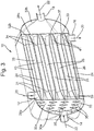
- FIG. 1 shows an embodiment of an elongated heat exchanger 10 in accordance with the present disclosure.
- the heat exchanger 10 is shown having a substantially square cross section in a plane that is orthogonal to the longitudinal axis.
- the heat exchanger 10 may have any suitable cross section, for example depending on the space available where it is desired to be installed.
- it may have a substantially C-shaped cross section.
- the heat exchanger includes two flow paths, which are fluidly isolated from one another, i.e. the fluids are maintained separate and do not intermix.
- the heat exchanger 10 includes a first inlet 12 and a first outlet 16 relating to a first flow path for a first fluid, and a second inlet 14 and a second outlet 18 relating to a second flow path for a second fluid.
- a first stream of fluid 20 will flow through the first flow path from the first inlet 12 to the first outlet 16, and a second stream of fluid 22 will flow through the second flow path from the second inlet 14 to the second outlet 18.
- the temperature differential between the two streams of fluid will be reduced along their flow paths as the hot fluid exchanges its heat energy to the cold fluid as the fluids progress to the outlets 16,18: i.e. the hotter fluid will become cooler, and the cooler fluid will become hotter.
- the first fluid may be in gaseous and/or liquid form for at least part of the first flow path; and/or the second fluid may be in gaseous and/or liquid form for at least part of the second flow path.
- Figure 2 shows a cross sectional view of the upstream portion of the heat exchanger of Figure 1 that would be seen if it was cut along its width, i.e. cut in a plane defined by the width direction and line A of Figure 1 .
- the heat exchanger includes a plurality of fluid channels 24,26. Each channel is associated with one of the first and second flow paths, i.e. the ends of any given channel are either in communication with first fluid inlet 12 and first fluid outlet 16 or are alternatively in communication with second fluid inlet 14 and second fluid outlet 18.
- a plurality of first channels 24 form part of the first flow path
- a plurality of second channels 26 form part of the second flow path.
- Each of the first and second channels 24,26 may have a substantially diamond or rhombus cross-sectional shape (in the plane orthogonal to the longitudinal axis).
- the plurality of first channels 24 are arranged laterally (i.e. radially) between the plurality of second channels 26, and vice versa, such that each wall of each channel is a primary heat exchange surface, aside from for the channels at the radial edges of the heat exchanger 10.
- four walls of each of the plurality of first channels also form the walls of second channels, and vice four walls of each of the plurality of second channels also form the walls of first channels, except for the channels located at the radial edges of the heat exchanger 10. This provides for efficient heat exchange between the channels.
- Figure 3 shows a cross sectional view of the heat exchanger of Figures 1 and 2 , that would be seen if it was cut along its length in a plane defined by the longitudinal axis and line C in Figure 2 .
- First and second channels 24 and 26 extend longitudinally through the heat exchanger, parallel to one another. In longitudinal end portions of the heat exchanger, each second flow channel 26 tapers such that its cross section becomes smaller in a direction away from the longitudinal centre of the channel. The end portions 39, 41 of the second flow channels 26 beyond the first flow channels 24 taper down towards parting walls 32a,32b.
- the parting walls 32a,32b have orifices 33 therethrough and the orifices in the ends 35, 37 of the second flow channels 26 coincide with orifices 33 in the parting walls 32a,32b.
- the end portions 39, 41 of the second flow channels 26 taper down, this results in the first channels 24 being shorter than the second channels 26 and terminating at first and second ends 31 34.
- the end portions 39,41 of the second flow channels 26 may decrease in cross sectional area whilst maintaining the same shape, i.e. the dimensions thereof decrease whilst staying the same relative to one another.
- the end portions 39,41 of the second flow channels 26 may decrease in cross sectional area and have a different cross-sectional shape to the central portion 43 between the end portions 39, 41.
- the second flow channels 26 may have a substantially diamond or rhombus cross-sectional shape (in the plane orthogonal to the longitudinal axis) in a portion 43 between the end portions 39, 41, but may have an oval or circular cross-sectional shape in the end portions 39,41.
- the end portions 39,41 of the second flow channels may have a cross-sectional shape that is different to the central portion 43 but has the same cross-sectional area.
- the second flow channels 26 may have a substantially diamond or rhombus cross-sectional shape (in the plane orthogonal to the longitudinal axis) in a middle portion 43 between the end portions 39, 41, which may change to a circular or oval shape (in the end portions 39,41) having the same cross sectional area as the diamond or rhombus of the middle portion.
- the change in shape may be gradual or stepped.
- the upstream ends of all of the first channels 24 are in fluid communication with each other, as the fluid 20 is able to flow around the reduced cross section ends of the second channels 24 and between the upstream ends of the first channels 24.
- the fluid 20 is unable to flow through parting wall 32a, as the orifices 33 therein are coincident with the openings into the second channels 26.
- a first inlet chamber 28a is therefore defined between the upstream ends of the first channels 24, the upstream parting wall 32a and the external housing of the heat exchanger.
- First inlet 12 is able to supply fluid 20 into the first inlet chamber 28a such that it can flow around the tapered ends of the second channels 26 and pass into the upstream ends of the first channels 24.
- First inlet 12 may be arranged to supply fluid into the top of the heat exchanger.
- the housing of the heat exchanger and the parting wall 32a define a second inlet chamber 30a, located on the other side of the parting wall 32a to the channels 24,26.
- the second fluid is able to be supplied into the second inlet chamber 30a through second inlet 14.
- Fluid 20 is able to flow out of the downstream ends of the first channels 24 and around the reduced diameter ends of the second channels 24.
- the fluid 20 is unable to flow through parting wall 32b, as the orifices therein are coincident with the downstream openings into the second channels 26.
- a first outlet chamber 28b is therefore defined between the downstream ends of the first channels 24, the downstream parting wall 32b and the external housing of the heat exchanger.
- First outlet 16 may be arranged to allow fluid to exit the bottom of the heat exchanger.
- the housing of the heat exchanger and the downstream parting wall 32b define a second outlet chamber 30b, located on the other side of the parting wall 32b to the channels 24,26.
- the second fluid 22 is able to pass from the second flow channels 26 through the orifices in the downstream parting wall 32b and into the second outlet chamber. The second fluid 22 may then exit the heat exchanger through second outlet 18.
- the first fluid 20 is supplied to the first inlet 12 and passes into the first inlet chamber 28a.
- the first fluid 20 flows around the outsides of the tapered, upstream ends of the second channels 26 so as to fill the first inlet chamber 28a.
- the first fluid 20 enters the upstream ends 31 of the first channels 24 and travels through these channels and out of their downstream ends 34 into the first outlet chamber 28b.
- the first fluid 20 is able to flow around the outsides of the tapered, downstream ends of the second channels 26 to the first outlet 16.
- the arrows in Figure 4 show the above-described flow of the first fluid 20 through the heat exchanger. More specifically, Figure 4 shows a view of the portion the heat exchanger of Figures 1-3 from the first inlet 12 to the downstream end. Figure 4 shows a cross sectional view of this portion, that would be seen if the heat exchanger was cut along its length in a plane defined by the longitudinal axis and line D in Figure 2 .
- Figure 5 shows a cross section of the heat exchanger that would be seen if it was cut along its length in a plane defined by the longitudinal axis and line E in Figure 2 .
- This arrows in this Figure show the second flow path through the heat exchanger.
- the second fluid flows into the second inlet 14 and into second inlet chamber 30a.
- the fluid fills the second inlet chamber 30a and passes through the orifices 33 in the upstream parting plate 32a and into the second channels 26.
- the second fluid flows along the second channels 26 and passes out of the downstream ends 37 of these channels and into the second outlet chamber 30b.
- the second fluid 22 then passes out of the second outlet 18.
- the first and second fluids flow through the heat exchanger simultaneously such that heat in one of the fluids is passed into the other fluid.
- the channels may have various forms, such as wave channels (i.e. having waved sides or surface, such as sinusoidal waves). Such channels may induce turbulence in fluid flow therein.
- the heat exchanger may be formed using any suitable manufacturing process. However, in preferred embodiments, the heat exchanger is formed using an additive manufacturing method such as 3D printing.
- the heat changer may be 3D printed from one longitudinal end thereof to the other.
- An alternative embodiment may be substantially the same as that described above, aside from the end portions 39 of the second fluid channels being of a different cross-sectional shape to the rest of the channel.
- the orifices 33 in the parting walls 32a,32b are therefore also modified so as to have the same different cross-sectional shape as the end portions 39.
- the cross-sectional area in the end portions 39 may be the same as (or smaller than) the cross sectional area in the rest of the second fluid channels.
- the longitudinally central portions 43 (i.e. the lengths between the end portions) of the second fluid channels 26 have rhombus shaped cross-sections, whereas the end portions 39 have oval shaped cross-sections.
- the cross sectional areas of each of the second fluid channels 26 may remain constant along its entire length. As such, a fluid pressure drop is prevented along the channels. Fluid is able to flow between the end portions 39 of the second fluid channels 26 in the first inlet chamber 28a, in the manner described above.
- the ends of the second flow channels are depicted as tapering gradually and progressively, they could alternatively step down in cross-section.
Landscapes
- Engineering & Computer Science (AREA)
- Physics & Mathematics (AREA)
- Thermal Sciences (AREA)
- Mechanical Engineering (AREA)
- General Engineering & Computer Science (AREA)
- Geometry (AREA)
- Chemical & Material Sciences (AREA)
- Manufacturing & Machinery (AREA)
- Materials Engineering (AREA)
- Heat-Exchange Devices With Radiators And Conduit Assemblies (AREA)
Priority Applications (2)
| Application Number | Priority Date | Filing Date | Title |
|---|---|---|---|
| EP19461554.8A EP3760962B1 (de) | 2019-07-05 | 2019-07-05 | Wärmetauscher |
| US16/719,582 US11754341B2 (en) | 2019-07-05 | 2019-12-18 | Heat exchanger |
Applications Claiming Priority (1)
| Application Number | Priority Date | Filing Date | Title |
|---|---|---|---|
| EP19461554.8A EP3760962B1 (de) | 2019-07-05 | 2019-07-05 | Wärmetauscher |
Publications (2)
| Publication Number | Publication Date |
|---|---|
| EP3760962A1 true EP3760962A1 (de) | 2021-01-06 |
| EP3760962B1 EP3760962B1 (de) | 2023-08-30 |
Family
ID=67211657
Family Applications (1)
| Application Number | Title | Priority Date | Filing Date |
|---|---|---|---|
| EP19461554.8A Active EP3760962B1 (de) | 2019-07-05 | 2019-07-05 | Wärmetauscher |
Country Status (2)
| Country | Link |
|---|---|
| US (1) | US11754341B2 (de) |
| EP (1) | EP3760962B1 (de) |
Cited By (1)
| Publication number | Priority date | Publication date | Assignee | Title |
|---|---|---|---|---|
| WO2024114973A1 (de) * | 2022-11-30 | 2024-06-06 | Arvos Gmbh | Wärmeübertrager mit mehreren rohren |
Families Citing this family (16)
| Publication number | Priority date | Publication date | Assignee | Title |
|---|---|---|---|---|
| US9987508B2 (en) * | 2016-08-31 | 2018-06-05 | Emerson Process Management Regulator Technologies Tulsa, Llc | Hybrid composite flame cell |
| SG11202012923YA (en) * | 2018-06-29 | 2021-01-28 | Nat Univ Singapore | Heat exchange unit and method of manufacture thereof |
| US10955200B2 (en) * | 2018-07-13 | 2021-03-23 | General Electric Company | Heat exchangers having a three-dimensional lattice structure with baffle cells and methods of forming baffles in a three-dimensional lattice structure of a heat exchanger |
| JP7479202B2 (ja) * | 2020-06-03 | 2024-05-08 | 本田技研工業株式会社 | 熱交換器 |
| CN113251836B (zh) * | 2021-06-04 | 2025-03-04 | 江苏科技大学 | 一种紧凑型微通道lng换热器及其制备方法 |
| CN113970257B (zh) * | 2021-10-29 | 2024-01-30 | 台州龙江化工机械科技有限公司 | 一种冷却装置、油气分离器以及制冷系统 |
| GB2613014A (en) * | 2021-11-22 | 2023-05-24 | Edwards Ltd | Heat exchanger |
| FR3130949B1 (fr) * | 2021-12-16 | 2024-01-05 | Commissariat Energie Atomique | Echangeur de chaleur à calandre et tubes |
| KR102704954B1 (ko) * | 2021-12-17 | 2024-09-09 | 한국기계연구원 | 방빙성 타원형 튜브 적용 극저온 열교환기 |
| GB2624906A (en) * | 2022-11-30 | 2024-06-05 | Bae Systems Plc | Heat exchanger |
| FR3142797B1 (fr) | 2022-12-06 | 2025-01-03 | Commissariat Energie Atomique | Echangeur de chaleur à structure alvéolaire |
| CN115942598B (zh) * | 2023-01-09 | 2023-05-16 | 西安交通大学 | 一种模块化的方圆复合通道印刷电路板换热器 |
| DE102023202185A1 (de) * | 2023-03-10 | 2024-09-12 | Mahle International Gmbh | Additiv Gefertigter Wärmeübertrager |
| DE102023202186A1 (de) * | 2023-03-10 | 2024-09-12 | Mahle International Gmbh | Additiv gefertigter Wärmeübertrager |
| JP2024141558A (ja) * | 2023-03-29 | 2024-10-10 | 本田技研工業株式会社 | 熱交換器及びその製造方法 |
| EP4477981B1 (de) * | 2023-06-16 | 2026-04-29 | Hamilton Sundstrand Corporation | Wärmetauscherkerndesign |
Citations (3)
| Publication number | Priority date | Publication date | Assignee | Title |
|---|---|---|---|---|
| FR2812718A1 (fr) * | 2000-08-04 | 2002-02-08 | Ciat Sa | Tube d'echange thermique et echangeur de chaleur intratubulaire muni de tels tubes |
| US20170089643A1 (en) * | 2015-09-25 | 2017-03-30 | Westinghouse Electric Company, Llc. | Heat Exchanger |
| EP3239642A1 (de) * | 2016-01-15 | 2017-11-01 | Hamilton Sundstrand Corporation | Wärmetauscher |
Family Cites Families (26)
| Publication number | Priority date | Publication date | Assignee | Title |
|---|---|---|---|---|
| US910192A (en) * | 1906-04-27 | 1909-01-19 | Philippe Jules Grouvelle | Tube. |
| US1277526A (en) * | 1914-11-12 | 1918-09-03 | Schutte & Koerting Company | Heat-exchanging apparatus. |
| US1618485A (en) * | 1925-07-22 | 1927-02-22 | Fred A C Skinner | Radiator |
| US1946234A (en) * | 1931-05-19 | 1934-02-06 | Griscom Russell Co | Heat exchanger |
| US4730669A (en) * | 1986-02-03 | 1988-03-15 | Long Manufacturing Ltd. | Heat exchanger core construction utilizing a diamond-shaped tube-to-header joint configuration |
| US5046555A (en) * | 1990-09-06 | 1991-09-10 | General Motors Corporation | Extended surface tube-to-header connection for condenser |
| DE4212717A1 (de) * | 1992-04-16 | 1993-10-21 | Laengerer & Reich Gmbh & Co | Wärmeaustauscher |
| JPH0684188U (ja) * | 1993-04-26 | 1994-12-02 | サンデン株式会社 | 熱交換器 |
| US8459342B2 (en) * | 2003-11-25 | 2013-06-11 | Beckett Gas, Inc. | Heat exchanger tube with integral restricting and turbulating structure |
| EP2584301B1 (de) * | 2011-10-19 | 2014-08-13 | WS-Wärmeprozesstechnik GmbH | Hochtemperatur-Wärmeübertrager |
| EP3071913B1 (de) * | 2013-11-18 | 2020-06-03 | General Electric Company | Monolithische röhre-in einem matrixwärmetauscher |
| US9976815B1 (en) * | 2014-02-20 | 2018-05-22 | Hrl Laboratories, Llc | Heat exchangers made from additively manufactured sacrificial templates |
| KR102291151B1 (ko) * | 2014-11-03 | 2021-08-19 | 현대모비스 주식회사 | 전력변환장치용 냉각유로모듈 및 이를 구비한 전력변화장치 |
| US10527362B2 (en) | 2015-09-21 | 2020-01-07 | Lockheed Martin Corporation | Integrated multi-chamber heat exchanger |
| US10371462B2 (en) * | 2015-09-21 | 2019-08-06 | Lockheed Martin Corporation | Integrated multi-chamber heat exchanger |
| US20170146305A1 (en) * | 2015-11-24 | 2017-05-25 | Hamilton Sundstrand Corporation | Header for heat exchanger |
| US20170198976A1 (en) | 2016-01-13 | 2017-07-13 | Hamilton Sundstrand Corporation | Heat exchangers |
| US20170198979A1 (en) * | 2016-01-13 | 2017-07-13 | Hamilton Sundstrand Corporation | Heat exchangers |
| US20170198978A1 (en) | 2016-01-13 | 2017-07-13 | Hamilton Sundstrand Corporation | Heat exchangers |
| US11243030B2 (en) | 2016-01-13 | 2022-02-08 | Hamilton Sundstrand Corporation | Heat exchangers |
| US11112183B2 (en) | 2016-01-14 | 2021-09-07 | Hamilton Sundstrand Corporation | Heat exchanger channels |
| WO2017214489A1 (en) | 2016-06-09 | 2017-12-14 | Fluid Handling Llc | 3d spiral heat exchanger |
| US10107555B1 (en) * | 2017-04-21 | 2018-10-23 | Unison Industries, Llc | Heat exchanger assembly |
| US10203169B2 (en) * | 2017-06-12 | 2019-02-12 | Microsoft Technology Licensing, Llc | Thermal management devices, systems and methods |
| US11226158B2 (en) * | 2019-04-01 | 2022-01-18 | Hamilton Sundstrand Corporation | Heat exchanger fractal splitter |
| US11156381B2 (en) * | 2019-10-03 | 2021-10-26 | Johnson Controls Technology Company | Motor mount for HVAC system |
-
2019
- 2019-07-05 EP EP19461554.8A patent/EP3760962B1/de active Active
- 2019-12-18 US US16/719,582 patent/US11754341B2/en active Active
Patent Citations (3)
| Publication number | Priority date | Publication date | Assignee | Title |
|---|---|---|---|---|
| FR2812718A1 (fr) * | 2000-08-04 | 2002-02-08 | Ciat Sa | Tube d'echange thermique et echangeur de chaleur intratubulaire muni de tels tubes |
| US20170089643A1 (en) * | 2015-09-25 | 2017-03-30 | Westinghouse Electric Company, Llc. | Heat Exchanger |
| EP3239642A1 (de) * | 2016-01-15 | 2017-11-01 | Hamilton Sundstrand Corporation | Wärmetauscher |
Cited By (1)
| Publication number | Priority date | Publication date | Assignee | Title |
|---|---|---|---|---|
| WO2024114973A1 (de) * | 2022-11-30 | 2024-06-06 | Arvos Gmbh | Wärmeübertrager mit mehreren rohren |
Also Published As
| Publication number | Publication date |
|---|---|
| EP3760962B1 (de) | 2023-08-30 |
| US11754341B2 (en) | 2023-09-12 |
| US20210003349A1 (en) | 2021-01-07 |
Similar Documents
| Publication | Publication Date | Title |
|---|---|---|
| US11754341B2 (en) | Heat exchanger | |
| EP3640574B1 (de) | Gegenstrom-wärmetauscher mit schraubenförmigen kanälen | |
| US20110139413A1 (en) | Flow distributor for a heat exchanger assembly | |
| US10215497B2 (en) | Heat exchanger and production method for heat exchanger | |
| CN110268216B (zh) | 换热板和换热器 | |
| KR102145084B1 (ko) | 판형 열교환기 | |
| US20170089643A1 (en) | Heat Exchanger | |
| EP1644683B1 (de) | Wärmetauscherrohr | |
| EP3604998A1 (de) | Gegenstromwärmetauscher | |
| US9921000B2 (en) | Heat exchanger comprising one or more plate assemblies with a plurality of interconnected channels and related method | |
| US11209213B2 (en) | Heat exchanger | |
| CN103988042A (zh) | 用于热交换器的板和配备有这样的板的热交换器 | |
| US20110240275A1 (en) | Low thermal strain multi-cooler | |
| JP7528078B2 (ja) | マイクロチャネル熱交換器 | |
| EP4109027A1 (de) | Wellenförmiger wärmetauscherkern mit angrenzendem durchgang und verteiler | |
| KR20160042182A (ko) | 열교환기용 튜브 | |
| KR20190098190A (ko) | 열 교환기용 헤더 및 열 교환기 | |
| US20180156544A1 (en) | Two phase distributor evaporator | |
| CN110462331A (zh) | 具有调节通道部分的液/气混合器装置的热交换器 | |
| US20200408466A1 (en) | Heat exchanger with improved liquid/gas mixing device | |
| US10458714B2 (en) | Heat exchanger assembly | |
| JP7805162B2 (ja) | 熱交換器用プレート、熱交換器用プレート積層体、及びマイクロチャンネル熱交換器 | |
| US20180010864A1 (en) | Heat exchanger with interleaved passages | |
| JP2023041317A (ja) | 熱交換器 | |
| KR101673605B1 (ko) | 공기조화기용 증발기 |
Legal Events
| Date | Code | Title | Description |
|---|---|---|---|
| PUAI | Public reference made under article 153(3) epc to a published international application that has entered the european phase |
Free format text: ORIGINAL CODE: 0009012 |
|
| STAA | Information on the status of an ep patent application or granted ep patent |
Free format text: STATUS: THE APPLICATION HAS BEEN PUBLISHED |
|
| AK | Designated contracting states |
Kind code of ref document: A1 Designated state(s): AL AT BE BG CH CY CZ DE DK EE ES FI FR GB GR HR HU IE IS IT LI LT LU LV MC MK MT NL NO PL PT RO RS SE SI SK SM TR |
|
| AX | Request for extension of the european patent |
Extension state: BA ME |
|
| STAA | Information on the status of an ep patent application or granted ep patent |
Free format text: STATUS: REQUEST FOR EXAMINATION WAS MADE |
|
| 17P | Request for examination filed |
Effective date: 20210706 |
|
| RBV | Designated contracting states (corrected) |
Designated state(s): AL AT BE BG CH CY CZ DE DK EE ES FI FR GB GR HR HU IE IS IT LI LT LU LV MC MK MT NL NO PL PT RO RS SE SI SK SM TR |
|
| GRAP | Despatch of communication of intention to grant a patent |
Free format text: ORIGINAL CODE: EPIDOSNIGR1 |
|
| STAA | Information on the status of an ep patent application or granted ep patent |
Free format text: STATUS: GRANT OF PATENT IS INTENDED |
|
| RIC1 | Information provided on ipc code assigned before grant |
Ipc: F28F 9/02 20060101ALI20221103BHEP Ipc: F28F 1/02 20060101ALI20221103BHEP Ipc: F28F 1/00 20060101ALI20221103BHEP Ipc: F28D 7/16 20060101ALI20221103BHEP Ipc: F28F 7/02 20060101AFI20221103BHEP |
|
| INTG | Intention to grant announced |
Effective date: 20221124 |
|
| GRAS | Grant fee paid |
Free format text: ORIGINAL CODE: EPIDOSNIGR3 |
|
| GRAA | (expected) grant |
Free format text: ORIGINAL CODE: 0009210 |
|
| STAA | Information on the status of an ep patent application or granted ep patent |
Free format text: STATUS: THE PATENT HAS BEEN GRANTED |
|
| AK | Designated contracting states |
Kind code of ref document: B1 Designated state(s): AL AT BE BG CH CY CZ DE DK EE ES FI FR GB GR HR HU IE IS IT LI LT LU LV MC MK MT NL NO PL PT RO RS SE SI SK SM TR |
|
| REG | Reference to a national code |
Ref country code: GB Ref legal event code: FG4D |
|
| REG | Reference to a national code |
Ref country code: CH Ref legal event code: EP |
|
| REG | Reference to a national code |
Ref country code: DE Ref legal event code: R096 Ref document number: 602019036077 Country of ref document: DE |
|
| REG | Reference to a national code |
Ref country code: IE Ref legal event code: FG4D |
|
| REG | Reference to a national code |
Ref country code: LT Ref legal event code: MG9D |
|
| REG | Reference to a national code |
Ref country code: NL Ref legal event code: MP Effective date: 20230830 |
|
| REG | Reference to a national code |
Ref country code: AT Ref legal event code: MK05 Ref document number: 1605952 Country of ref document: AT Kind code of ref document: T Effective date: 20230830 |
|
| PG25 | Lapsed in a contracting state [announced via postgrant information from national office to epo] |
Ref country code: GR Free format text: LAPSE BECAUSE OF FAILURE TO SUBMIT A TRANSLATION OF THE DESCRIPTION OR TO PAY THE FEE WITHIN THE PRESCRIBED TIME-LIMIT Effective date: 20231201 |
|
| PG25 | Lapsed in a contracting state [announced via postgrant information from national office to epo] |
Ref country code: IS Free format text: LAPSE BECAUSE OF FAILURE TO SUBMIT A TRANSLATION OF THE DESCRIPTION OR TO PAY THE FEE WITHIN THE PRESCRIBED TIME-LIMIT Effective date: 20231230 |
|
| PG25 | Lapsed in a contracting state [announced via postgrant information from national office to epo] |
Ref country code: SE Free format text: LAPSE BECAUSE OF FAILURE TO SUBMIT A TRANSLATION OF THE DESCRIPTION OR TO PAY THE FEE WITHIN THE PRESCRIBED TIME-LIMIT Effective date: 20230830 Ref country code: RS Free format text: LAPSE BECAUSE OF FAILURE TO SUBMIT A TRANSLATION OF THE DESCRIPTION OR TO PAY THE FEE WITHIN THE PRESCRIBED TIME-LIMIT Effective date: 20230830 Ref country code: NO Free format text: LAPSE BECAUSE OF FAILURE TO SUBMIT A TRANSLATION OF THE DESCRIPTION OR TO PAY THE FEE WITHIN THE PRESCRIBED TIME-LIMIT Effective date: 20231130 Ref country code: LV Free format text: LAPSE BECAUSE OF FAILURE TO SUBMIT A TRANSLATION OF THE DESCRIPTION OR TO PAY THE FEE WITHIN THE PRESCRIBED TIME-LIMIT Effective date: 20230830 Ref country code: LT Free format text: LAPSE BECAUSE OF FAILURE TO SUBMIT A TRANSLATION OF THE DESCRIPTION OR TO PAY THE FEE WITHIN THE PRESCRIBED TIME-LIMIT Effective date: 20230830 Ref country code: IS Free format text: LAPSE BECAUSE OF FAILURE TO SUBMIT A TRANSLATION OF THE DESCRIPTION OR TO PAY THE FEE WITHIN THE PRESCRIBED TIME-LIMIT Effective date: 20231230 Ref country code: HR Free format text: LAPSE BECAUSE OF FAILURE TO SUBMIT A TRANSLATION OF THE DESCRIPTION OR TO PAY THE FEE WITHIN THE PRESCRIBED TIME-LIMIT Effective date: 20230830 Ref country code: GR Free format text: LAPSE BECAUSE OF FAILURE TO SUBMIT A TRANSLATION OF THE DESCRIPTION OR TO PAY THE FEE WITHIN THE PRESCRIBED TIME-LIMIT Effective date: 20231201 Ref country code: FI Free format text: LAPSE BECAUSE OF FAILURE TO SUBMIT A TRANSLATION OF THE DESCRIPTION OR TO PAY THE FEE WITHIN THE PRESCRIBED TIME-LIMIT Effective date: 20230830 Ref country code: AT Free format text: LAPSE BECAUSE OF FAILURE TO SUBMIT A TRANSLATION OF THE DESCRIPTION OR TO PAY THE FEE WITHIN THE PRESCRIBED TIME-LIMIT Effective date: 20230830 |
|
| PG25 | Lapsed in a contracting state [announced via postgrant information from national office to epo] |
Ref country code: PL Free format text: LAPSE BECAUSE OF FAILURE TO SUBMIT A TRANSLATION OF THE DESCRIPTION OR TO PAY THE FEE WITHIN THE PRESCRIBED TIME-LIMIT Effective date: 20230830 Ref country code: NL Free format text: LAPSE BECAUSE OF FAILURE TO SUBMIT A TRANSLATION OF THE DESCRIPTION OR TO PAY THE FEE WITHIN THE PRESCRIBED TIME-LIMIT Effective date: 20230830 |
|
| PG25 | Lapsed in a contracting state [announced via postgrant information from national office to epo] |
Ref country code: ES Free format text: LAPSE BECAUSE OF FAILURE TO SUBMIT A TRANSLATION OF THE DESCRIPTION OR TO PAY THE FEE WITHIN THE PRESCRIBED TIME-LIMIT Effective date: 20230830 |
|
| PG25 | Lapsed in a contracting state [announced via postgrant information from national office to epo] |
Ref country code: SM Free format text: LAPSE BECAUSE OF FAILURE TO SUBMIT A TRANSLATION OF THE DESCRIPTION OR TO PAY THE FEE WITHIN THE PRESCRIBED TIME-LIMIT Effective date: 20230830 Ref country code: RO Free format text: LAPSE BECAUSE OF FAILURE TO SUBMIT A TRANSLATION OF THE DESCRIPTION OR TO PAY THE FEE WITHIN THE PRESCRIBED TIME-LIMIT Effective date: 20230830 Ref country code: ES Free format text: LAPSE BECAUSE OF FAILURE TO SUBMIT A TRANSLATION OF THE DESCRIPTION OR TO PAY THE FEE WITHIN THE PRESCRIBED TIME-LIMIT Effective date: 20230830 Ref country code: EE Free format text: LAPSE BECAUSE OF FAILURE TO SUBMIT A TRANSLATION OF THE DESCRIPTION OR TO PAY THE FEE WITHIN THE PRESCRIBED TIME-LIMIT Effective date: 20230830 Ref country code: DK Free format text: LAPSE BECAUSE OF FAILURE TO SUBMIT A TRANSLATION OF THE DESCRIPTION OR TO PAY THE FEE WITHIN THE PRESCRIBED TIME-LIMIT Effective date: 20230830 Ref country code: CZ Free format text: LAPSE BECAUSE OF FAILURE TO SUBMIT A TRANSLATION OF THE DESCRIPTION OR TO PAY THE FEE WITHIN THE PRESCRIBED TIME-LIMIT Effective date: 20230830 Ref country code: PT Free format text: LAPSE BECAUSE OF FAILURE TO SUBMIT A TRANSLATION OF THE DESCRIPTION OR TO PAY THE FEE WITHIN THE PRESCRIBED TIME-LIMIT Effective date: 20240102 Ref country code: SK Free format text: LAPSE BECAUSE OF FAILURE TO SUBMIT A TRANSLATION OF THE DESCRIPTION OR TO PAY THE FEE WITHIN THE PRESCRIBED TIME-LIMIT Effective date: 20230830 |
|
| PG25 | Lapsed in a contracting state [announced via postgrant information from national office to epo] |
Ref country code: IT Free format text: LAPSE BECAUSE OF FAILURE TO SUBMIT A TRANSLATION OF THE DESCRIPTION OR TO PAY THE FEE WITHIN THE PRESCRIBED TIME-LIMIT Effective date: 20230830 |
|
| REG | Reference to a national code |
Ref country code: DE Ref legal event code: R097 Ref document number: 602019036077 Country of ref document: DE |
|
| PLBE | No opposition filed within time limit |
Free format text: ORIGINAL CODE: 0009261 |
|
| STAA | Information on the status of an ep patent application or granted ep patent |
Free format text: STATUS: NO OPPOSITION FILED WITHIN TIME LIMIT |
|
| PG25 | Lapsed in a contracting state [announced via postgrant information from national office to epo] |
Ref country code: SI Free format text: LAPSE BECAUSE OF FAILURE TO SUBMIT A TRANSLATION OF THE DESCRIPTION OR TO PAY THE FEE WITHIN THE PRESCRIBED TIME-LIMIT Effective date: 20230830 |
|
| 26N | No opposition filed |
Effective date: 20240603 |
|
| PG25 | Lapsed in a contracting state [announced via postgrant information from national office to epo] |
Ref country code: BG Free format text: LAPSE BECAUSE OF FAILURE TO SUBMIT A TRANSLATION OF THE DESCRIPTION OR TO PAY THE FEE WITHIN THE PRESCRIBED TIME-LIMIT Effective date: 20230830 |
|
| PG25 | Lapsed in a contracting state [announced via postgrant information from national office to epo] |
Ref country code: BG Free format text: LAPSE BECAUSE OF FAILURE TO SUBMIT A TRANSLATION OF THE DESCRIPTION OR TO PAY THE FEE WITHIN THE PRESCRIBED TIME-LIMIT Effective date: 20230830 |
|
| PG25 | Lapsed in a contracting state [announced via postgrant information from national office to epo] |
Ref country code: MC Free format text: LAPSE BECAUSE OF FAILURE TO SUBMIT A TRANSLATION OF THE DESCRIPTION OR TO PAY THE FEE WITHIN THE PRESCRIBED TIME-LIMIT Effective date: 20230830 |
|
| REG | Reference to a national code |
Ref country code: CH Ref legal event code: PL |
|
| PG25 | Lapsed in a contracting state [announced via postgrant information from national office to epo] |
Ref country code: LU Free format text: LAPSE BECAUSE OF NON-PAYMENT OF DUE FEES Effective date: 20240705 |
|
| PG25 | Lapsed in a contracting state [announced via postgrant information from national office to epo] |
Ref country code: LU Free format text: LAPSE BECAUSE OF NON-PAYMENT OF DUE FEES Effective date: 20240705 |
|
| PG25 | Lapsed in a contracting state [announced via postgrant information from national office to epo] |
Ref country code: BE Free format text: LAPSE BECAUSE OF NON-PAYMENT OF DUE FEES Effective date: 20240731 Ref country code: CH Free format text: LAPSE BECAUSE OF NON-PAYMENT OF DUE FEES Effective date: 20240731 |
|
| REG | Reference to a national code |
Ref country code: BE Ref legal event code: MM Effective date: 20240731 |
|
| PGFP | Annual fee paid to national office [announced via postgrant information from national office to epo] |
Ref country code: GB Payment date: 20250619 Year of fee payment: 7 |
|
| PGFP | Annual fee paid to national office [announced via postgrant information from national office to epo] |
Ref country code: FR Payment date: 20250620 Year of fee payment: 7 |
|
| PG25 | Lapsed in a contracting state [announced via postgrant information from national office to epo] |
Ref country code: IE Free format text: LAPSE BECAUSE OF NON-PAYMENT OF DUE FEES Effective date: 20240705 |
|
| PGFP | Annual fee paid to national office [announced via postgrant information from national office to epo] |
Ref country code: DE Payment date: 20250620 Year of fee payment: 7 |
|
| PG25 | Lapsed in a contracting state [announced via postgrant information from national office to epo] |
Ref country code: CY Free format text: LAPSE BECAUSE OF FAILURE TO SUBMIT A TRANSLATION OF THE DESCRIPTION OR TO PAY THE FEE WITHIN THE PRESCRIBED TIME-LIMIT; INVALID AB INITIO Effective date: 20190705 |
|
| PG25 | Lapsed in a contracting state [announced via postgrant information from national office to epo] |
Ref country code: HU Free format text: LAPSE BECAUSE OF FAILURE TO SUBMIT A TRANSLATION OF THE DESCRIPTION OR TO PAY THE FEE WITHIN THE PRESCRIBED TIME-LIMIT; INVALID AB INITIO Effective date: 20190705 |