EP3760968B1 - Verfahren zur oct-bildgebung - Google Patents
Verfahren zur oct-bildgebung Download PDFInfo
- Publication number
- EP3760968B1 EP3760968B1 EP20182152.7A EP20182152A EP3760968B1 EP 3760968 B1 EP3760968 B1 EP 3760968B1 EP 20182152 A EP20182152 A EP 20182152A EP 3760968 B1 EP3760968 B1 EP 3760968B1
- Authority
- EP
- European Patent Office
- Prior art keywords
- image data
- oct
- pieces
- region
- dimensional
- Prior art date
- Legal status (The legal status is an assumption and is not a legal conclusion. Google has not performed a legal analysis and makes no representation as to the accuracy of the status listed.)
- Active
Links
Images






Classifications
-
- A—HUMAN NECESSITIES
- A61—MEDICAL OR VETERINARY SCIENCE; HYGIENE
- A61B—DIAGNOSIS; SURGERY; IDENTIFICATION
- A61B3/00—Apparatus for testing the eyes; Instruments for examining the eyes
- A61B3/0016—Operational features thereof
- A61B3/0025—Operational features thereof characterised by electronic signal processing, e.g. eye models
-
- A—HUMAN NECESSITIES
- A61—MEDICAL OR VETERINARY SCIENCE; HYGIENE
- A61B—DIAGNOSIS; SURGERY; IDENTIFICATION
- A61B3/00—Apparatus for testing the eyes; Instruments for examining the eyes
- A61B3/10—Objective types, i.e. instruments for examining the eyes independent of the patients' perceptions or reactions
- A61B3/12—Objective types, i.e. instruments for examining the eyes independent of the patients' perceptions or reactions for looking at the eye fundus, e.g. ophthalmoscopes
-
- A—HUMAN NECESSITIES
- A61—MEDICAL OR VETERINARY SCIENCE; HYGIENE
- A61B—DIAGNOSIS; SURGERY; IDENTIFICATION
- A61B5/00—Measuring for diagnostic purposes; Identification of persons
- A61B5/0059—Measuring for diagnostic purposes; Identification of persons using light, e.g. diagnosis by transillumination, diascopy, fluorescence
- A61B5/0062—Arrangements for scanning
- A61B5/0066—Optical coherence imaging
-
- G—PHYSICS
- G01—MEASURING; TESTING
- G01B—MEASURING LENGTH, THICKNESS OR SIMILAR LINEAR DIMENSIONS; MEASURING ANGLES; MEASURING AREAS; MEASURING IRREGULARITIES OF SURFACES OR CONTOURS
- G01B9/00—Measuring instruments characterised by the use of optical techniques
- G01B9/02—Interferometers
- G01B9/02055—Reduction or prevention of errors; Testing; Calibration
- G01B9/0207—Error reduction by correction of the measurement signal based on independently determined error sources, e.g. using a reference interferometer
- G01B9/02072—Error reduction by correction of the measurement signal based on independently determined error sources, e.g. using a reference interferometer by calibration or testing of interferometer
-
- G—PHYSICS
- G01—MEASURING; TESTING
- G01B—MEASURING LENGTH, THICKNESS OR SIMILAR LINEAR DIMENSIONS; MEASURING ANGLES; MEASURING AREAS; MEASURING IRREGULARITIES OF SURFACES OR CONTOURS
- G01B9/00—Measuring instruments characterised by the use of optical techniques
- G01B9/02—Interferometers
- G01B9/02083—Interferometers characterised by particular signal processing and presentation
-
- G—PHYSICS
- G01—MEASURING; TESTING
- G01B—MEASURING LENGTH, THICKNESS OR SIMILAR LINEAR DIMENSIONS; MEASURING ANGLES; MEASURING AREAS; MEASURING IRREGULARITIES OF SURFACES OR CONTOURS
- G01B9/00—Measuring instruments characterised by the use of optical techniques
- G01B9/02—Interferometers
- G01B9/0209—Low-coherence interferometers
- G01B9/02091—Tomographic interferometers, e.g. based on optical coherence
-
- G—PHYSICS
- G06—COMPUTING OR CALCULATING; COUNTING
- G06T—IMAGE DATA PROCESSING OR GENERATION, IN GENERAL
- G06T3/00—Geometric image transformations in the plane of the image
- G06T3/14—Transformations for image registration, e.g. adjusting or mapping for alignment of images
-
- G—PHYSICS
- G06—COMPUTING OR CALCULATING; COUNTING
- G06T—IMAGE DATA PROCESSING OR GENERATION, IN GENERAL
- G06T3/00—Geometric image transformations in the plane of the image
- G06T3/20—Linear translation of whole images or parts thereof, e.g. panning
-
- G—PHYSICS
- G06—COMPUTING OR CALCULATING; COUNTING
- G06T—IMAGE DATA PROCESSING OR GENERATION, IN GENERAL
- G06T3/00—Geometric image transformations in the plane of the image
- G06T3/60—Rotation of whole images or parts thereof
-
- G—PHYSICS
- G06—COMPUTING OR CALCULATING; COUNTING
- G06T—IMAGE DATA PROCESSING OR GENERATION, IN GENERAL
- G06T7/00—Image analysis
- G06T7/30—Determination of transform parameters for the alignment of images, i.e. image registration
- G06T7/32—Determination of transform parameters for the alignment of images, i.e. image registration using correlation-based methods
-
- A—HUMAN NECESSITIES
- A61—MEDICAL OR VETERINARY SCIENCE; HYGIENE
- A61B—DIAGNOSIS; SURGERY; IDENTIFICATION
- A61B3/00—Apparatus for testing the eyes; Instruments for examining the eyes
- A61B3/10—Objective types, i.e. instruments for examining the eyes independent of the patients' perceptions or reactions
- A61B3/102—Objective types, i.e. instruments for examining the eyes independent of the patients' perceptions or reactions for optical coherence tomography [OCT]
-
- G—PHYSICS
- G06—COMPUTING OR CALCULATING; COUNTING
- G06T—IMAGE DATA PROCESSING OR GENERATION, IN GENERAL
- G06T2200/00—Indexing scheme for image data processing or generation, in general
- G06T2200/04—Indexing scheme for image data processing or generation, in general involving 3D image data
-
- G—PHYSICS
- G06—COMPUTING OR CALCULATING; COUNTING
- G06T—IMAGE DATA PROCESSING OR GENERATION, IN GENERAL
- G06T2207/00—Indexing scheme for image analysis or image enhancement
- G06T2207/10—Image acquisition modality
- G06T2207/10072—Tomographic images
- G06T2207/10101—Optical tomography; Optical coherence tomography [OCT]
-
- G—PHYSICS
- G06—COMPUTING OR CALCULATING; COUNTING
- G06T—IMAGE DATA PROCESSING OR GENERATION, IN GENERAL
- G06T2207/00—Indexing scheme for image analysis or image enhancement
- G06T2207/20—Special algorithmic details
- G06T2207/20212—Image combination
-
- G—PHYSICS
- G06—COMPUTING OR CALCULATING; COUNTING
- G06T—IMAGE DATA PROCESSING OR GENERATION, IN GENERAL
- G06T2207/00—Indexing scheme for image analysis or image enhancement
- G06T2207/30—Subject of image; Context of image processing
- G06T2207/30004—Biomedical image processing
- G06T2207/30041—Eye; Retina; Ophthalmic
Definitions
- Embodiments described herein relate generally to a method of OCT imaging.
- OCT is an imaging technique capable of representing a light scattering medium at a resolution of micrometer level or less, and is used for medical imaging, nondestructive testing and the like.
- OCT is a low-coherence-interferometry-based technique and typically utilizes near infrared light to ensure the reaching depth of the light into a sample of a scattering medium.
- US Patent No. 7,884,945 discloses a method of processing an OCT data set represented as a function of optical depths that is obtained by a measurement of backscattering or back reflection in order to acquire OCT data efficiently and to acquire OCT data from a specific region of a sample accurately and in a short time.
- the method includes a step of analyzing an OCT data set to identify landmark region data of at least the first subset, a step of placing the OCT data set based on the landmark region data, and a step of processing at least the second subset of the OCT data set based on the correspondence between the OCT data set and the landmark region data.
- US Patent No. 8,405,834 discloses a method for monitoring disease progression.
- the method includes a step of acquiring an OCT survey scan data set represented as a function of optical depths that is obtained by a measurement of backscattering or back reflection, a step of analyzing the survey scan data set to identify a landmark region, a step of assigning a location in the sample or a location relating to a fixed position to an element of the survey scan data set to register part of the survey scan data set representing at least part of a diseased or affected tissue region relating to the landmark region, and a step of monitoring the changes in the diseased or affected tissue region at different points in time.
- An object of the present disclosure is to improve the efficiency of OCT data processing.
- a "processor” is, for example, a circuit (circuitry) such as a central processing unit (CPU), a graphics processing unit (GPU), an application specific integrated circuit (ASIC), a programmable logic device (e.g., a simple programmable logic device (SPLD)), a complex programmable logic device (CPLD), a field programable gate array (FPGA), or the like.
- the processor provides some examples for realizing desired functions, for example, by reading out and executing a program stored in a storage circuit or a storage device.
- OCT optical coherence tomography
- Swept source OCT is an imaging technique performed by splitting light emitted from a wavelength tunable light source into measurement light and reference light, superposing the return light of the measurement light returned from the sample with the reference light to generate interference light, detecting the interference light with a photodetector, and applying Fourier transform and other processes to the detected data acquired according to the wavelength sweeping and the measurement light scanning.
- Spectral domain OCT is an imaging technique performed by splitting light emitted from a low coherence light source (broadband light source) into measurement light and reference light, superposing the return light of the measurement light returned from the sample with the reference light to generate interference light, detecting the interference light using a spectrometer to obtain the spectral distribution thereof, and applying Fourier transform and other processes to the spectral distribution detected.
- a low coherence light source broadband light source
- swept source OCT is an OCT technique of acquiring the spectral distribution of the interference light by time division
- spectral domain OCT is an OCT technique of acquiring the spectral distribution of the interference light by space division.
- Types other than such Fourier domain OCT include time domain OCT and en-face OCT (or full field OCT).
- Time domain OCT introduces mechanical and sequential scanning in the axial direction (Z direction).
- En-face OCT provides two dimensional imaging of the XY plane orthogonal to the Z direction.
- exemplary aspects described below may be used in ophthalmic imaging, analysis, measurement, evaluation and the like. However, some exemplary aspects may be used in any fields other than ophthalmology such as medical departments other than ophthalmology (e.g., dermatology, dentistry, surgery) and industrial fields (e.g., nondestructive testing).
- medical departments other than ophthalmology
- industrial fields e.g., nondestructive testing
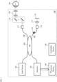
- FIGs. 1 and 2 show the configuration of the OCT apparatus (ophthalmic apparatus) 100 according to an exemplary aspect.
- the ophthalmic apparatus 100 provides an OCT imaging method.
- the ophthalmic apparatus 100 is configured to acquire three dimensional data sets from mutually different three dimensional regions of a sample (eye). Typically, the three dimensional regions are set in the manner that each of the three dimensional regions partially overlaps one or more other three dimensional regions.
- the ophthalmic apparatus 100 acquires three dimensional data sets respectively corresponding to the three dimensional regions by sequentially executing OCT scans respectively targeting the three dimensional regions.
- the order in which the OCT scans are applied, that is, the order assigned to the three dimensional regions is arbitrarily set.
- an order may be assigned to the three dimensional regions so that the n-th three dimensional region and the (n+1)-th three dimensional region partially and mutually overlap (where n is a positive integer).
- an order may be arbitrarily assigned to these three dimensional regions. Note that taking eye movements and the like into consideration, it is considerable that a region to which an OCT scan targeting a certain three dimensional region is actually applied does not coincide with this three dimensional region. However, a region that substantially coincides with this three dimensional region may be scanned using fixation and/or tracking.
- the number of three dimensional data sets acquired from one three dimensional region is not limited to one. For example, by acquiring two or more three dimensional data sets from a single three dimensional region, averaging for image quality improvement and motion contrast data generation (OCT angiography, etc.) may be executed in subsequent processing.
- OCT angiography motion contrast data generation
- the ophthalmic apparatus 100 is configured to generate a plurality of pieces of image data from three dimensional data sets acquired by the application of the OCT scans to the three dimensional regions. Thereby, a plurality of pieces of image data corresponding to the targeted three dimensional regions is obtained.
- the above-mentioned averaging and/or motion contrast data generation may be performed at this stage.
- the ophthalmic apparatus 100 is configured to perform registration (the first registration) between the plurality of pieces of image data by applying image correlation calculation to each of the overlap regions of the plurality of pieces of image data corresponding to the targeted three dimensional regions.
- the ophthalmic apparatus 100 is configured to arrange (or, register or align) the plurality of pieces of image data according to the image correlations of their overlap regions. Since the three dimensional regions are typically set in the manner that each of them partially overlaps with one or more others as described above, each image data partially overlaps with at least one other image data. By using the image correlation of such overlap regions, registration between these pieces of image data can be performed, and eventually, whole registration between the plurality of pieces of image data can be achieved.
- the ophthalmic apparatus 100 is configured to compose the plurality of pieces of image data based on the result of the whole registration between the plurality of pieces of image data.
- the resulting image data from such composition is referred to as panoramic image data or montage image data, and is computer graphics image data depicting a wider area than each of the original three dimensional regions.
- the ophthalmic apparatus 100 may be configured to designate an imaging region for the sample (eye). For example, the ophthalmic apparatus 100 may designate an imaging region to which an OCT scan is applied, in response to a command or instruction for designating an imaging region from the user. In another example, the ophthalmic apparatus 100 may designate an imaging region based on image data obtained from the sample by itself and/or image data of the sample obtained from another apparatus. In still another example, the ophthalmic apparatus 100 may designate an imaging region with reference to information on an imaging region designated in the past examination of the sample. Such past information is typically stored in a medical data system such as an electronic medical record system. Furthermore, the ophthalmic apparatus 100 may be configured to set target regions to include the imaging region designated.
- the union of the target regions includes the imaging region designated for the sample.
- the ophthalmic apparatus 100 may set target regions in response to a command or instruction for setting target regions from the user.
- the ophthalmic apparatus 100 may set target regions based on image data obtained from the sample by itself and/or image data of the sample obtained from another apparatus.
- the ophthalmic apparatus 100 may set target regions with reference to information on target regions set in the past examination of the sample. Such past information is typically stored in a medical data system such as an electronic medical record system.
- the ophthalmic apparatus 100 acquires three dimensional data sets corresponding to the three dimensional regions by sequentially applying OCT scans to the target regions set to include the imaging region.
- a certain target region and a three dimensional region to which an OCT scan is applied correspondingly may not coincide with each other due to the influence of eye movements or the like.
- a certain target region, a three dimensional region to which an OCT scan is applied correspondingly, and a three dimensional data set acquired by this OCT scan may be associated with each other.
- the ophthalmic apparatus 100 acquires two three dimensional data sets by applying OCT scans to two target regions (referred to as a target region pair) of the target regions that have been set to include the imaging region, and then generates two pieces of image data from the two three dimensional data sets. Further, the ophthalmic apparatus 100 may evaluate the overlap region between the two pieces of image data generated. Examples of the evaluation include an evaluation of the size of the overlap region, evaluation of the magnitude of the image correlation value, evaluation of the magnitude etc. of the relative movement amount (e.g., translation amount, rotation amount, etc.) from a preset positional relationship of the two pieces of image data. The ophthalmic apparatus 100 may select a subsequent process according to the result of the evaluation.
- the ophthalmic apparatus 100 may perform, in a selective manner according to the result of the evaluation, the application of the registration (the first registration described above) to the two pieces of image data, or the application of another OCT scan to at least one target region of the target region pair.
- the application of the registration is selected in the event that the evaluation result is good (suitable), and the application of another OCT scan is selected in the event that the evaluation result is not good.
- the evaluation typically includes a comparison with a preset threshold value.
- a good evaluation result is obtained, for example, in the event that the size of the overlap region is equal to or greater than the threshold value, in the event that the image correlation value is equal to or greater than the threshold value, or, in the event that the relative movement amount from the preset positional relationship between the two pieces of image data is less than the threshold value.
- Such a series of processes namely, application of OCT scans to a target region pair, generation of an image data pair, evaluation of an overlap region, and execution of selective processing according to the evaluation result
- target region pairs may be set according to the order assigned to the target regions.
- the n-th target region and the (n+1)-th target region may be paired (where n is a positive integer).
- target region pairs (n, n+1) set from five target regions are the following four: (1, 2), (2, 3), (3, 4) and (4, 5).
- the aspects of the target region pairs are not limited to the type of (n, n+1).
- a group of target region pairs may be set so that a set of target regions included in all the target region pairs covers the plurality of target regions that have been set to include the imaging region.
- a group of target region pairs may be set so that the set of target regions included in all target region pairs includes only part of the plurality of target regions that have been set to include the imaging region.
- a target region pair involved with this newly performed OCT scan may be the same as or at least partially different from the target region pair that has been involved with the previous (or earlier) OCT scan.
- the ophthalmic apparatus 100 may be configured to change at least one target region of the target region pairs applied to the previous (or earlier) OCT scan, based on the result of the overlap region evaluation.
- the ophthalmic apparatus 100 may use the result of the previous overlap region evaluation in such a way that the next overlap region evaluation gives a good result.
- the ophthalmic apparatus 100 may change (adjust, correct) one or both of the two target regions of the target region pair so that any of the followings is achieved: the overlap region size becomes equal to or greater than the threshold value; the image correlation value becomes equal to or greater than the threshold value; and the relative movement amount from the preset positional relationship between the two pieces of image data becomes less than the threshold value.
- the ophthalmic apparatus 100 may be configured to apply another OCT scan to the target region pair reflecting the change. For example, in the event that only one of the target regions of the target region pair is changed, the another OCT scan may be applied only to the changed one.
- an ophthalmic apparatus may be configured to prepare a front image of the sample.
- the ophthalmic apparatus of the present example may have any of the following functions: the function of photographing the sample from the front; the function of photographing the sample from one or more positions other than the front to construct the front image; the function of receiving the front image of the sample from an external device; and the function of reading out the front image of the sample from a recording medium.
- the ophthalmic apparatus of the present example may be configured to change at least one of the target regions of the target region pair based on the front image acquired.
- the change of a target region may include a series of processes as follows: specification (identification) of a partial region of the front image corresponding to that target region; registration between the front image and the image data generated based on a three dimensional data set acquired by an OCT scan on that target region; calculation of a positional difference amount of the image data with respect to the partial region specified; and movement of that target region to compensate for the positional difference amount.
- the target region change operation is not limited to the movement of the target region, and may include any aspect change in the target region, such as the change in the size, change in the shape, and change in the number of target regions.
- the ophthalmic apparatus of the present example may be configured to apply another OCT scan to the two target regions after such a change has been made. The ophthalmic apparatus of the present example will be described after the description of the ophthalmic apparatus 100.
- the ophthalmic apparatus 100 may be configured extract partial image data corresponding to the imaging region, from composite image data constructed by composing a plurality of pieces of image data corresponding to the target regions. As a result, three dimensional image data depicting the designated imaging region is obtained.
- the extraction of the partial image data includes the registration (alignment, positional adjustment) between the imaging region and the composite image data, and the extraction of the partial image data, from the composite image data, that corresponds to the imaging region identified by the registration.
- the registration may be performed using the front image.
- the ophthalmic apparatus 100 may be configured to extract partial image data from each of the plurality of pieces of image data corresponding to the target regions and compose the plurality of pieces of partial image data (the partial image data group) obtained in this way from the plurality of pieces of image data.
- the ophthalmic apparatus 100 may be configured to extract a partial image data group corresponding to the imaging region from the plurality of pieces of imaging data corresponding to the target regions based on the result of the first registration, and then compose the partial image data group.
- Such a configuration also gives three dimensional image data depicting the imaging region designated.
- the ophthalmic apparatus 100 applies the first registration using the image correlation calculation to two pieces of image data, having their overlap region, out of the plurality of pieces of image data generated based on the three dimensional data sets acquired from the mutually different three dimensional regions of the sample (eye).
- Any two pieces of image data (any pair of image data) that overlaps in part with one another is referred to as "the first and the second image data”.
- partial image data of the first image data corresponding to that overlap region is referred to as "the overlap region in the first image data”; and, similarly, partial image data of the second image data corresponding to the overlap region is referred to as "the overlap region in the second image data”.
- the image correlation calculation executed by the ophthalmic apparatus 100 may be the calculation of at least one of the translation amount and the rotation amount between the overlap regions in the first and second image data.
- the translation amount may be a three dimensional translation amount, and typically include three translation amount components in the three directions respectively indicated by the three coordinate axes of a three dimensional orthogonal coordinate system.
- the rotation amount may be a three dimensional rotation amount, and typically include three rotation amount components about the three coordinate axes of the three dimensional orthogonal coordinate system.
- An example of calculation techniques adoptable for such image correlation calculation is phase only correlation (POC).
- the phase only correlation may be, for example, the two dimensional technique disclosed in Japanese Patent No. 6,276,943 (International Patent Publication No.
- the ophthalmic apparatus 100 may be configured to use the two dimensional technique for each of the XY coordinate system, the YZ coordinate system, and the ZX coordinate system of the three dimensional orthogonal coordinate system (XYZ coordinate system).
- the ophthalmic apparatus 100 may be configured to use an arithmetic expression obtained by natural extension of the arithmetic expression of the two dimensional technique to the three dimensional space.
- arithmetic expressions for the three dimensional phase only correlation may be obtained as natural extensions of the arithmetic expressions (1) to (7) for the two dimensional phase only correlation described in Japanese Patent No. 6,276,943 (International Patent Publication No. WO2015/029675 ).
- the exemplary ophthalmic apparatus 100 shown in FIG. 1 includes the light source 102 that generates a light beam.
- the light source 102 is, for example, a broadband light source or a wavelength tunable light source.
- the beam splitter (BS) 104 splits the light beam emitted from the light source 102 into a sample light beam (measurement light) and a reference light beam (reference light). In other words, the beam splitter 104 directs part of the light beam emitted from the light source 102 to the sample arm 106 and another part to the reference arm 108.
- the reference arm 108 includes the polarization controller 110 and the collimator 112.
- the polarization controller 110 is used for regulating the reference light beam, for example, for maximizing the interference efficiency.
- the collimator 112 outputs the reference light beam as a collimated light beam (parallel light beam).
- the reference light beam output from the collimator 112 is converted into a convergent light beam by the lens 114 and projected onto the reflecting mirror 115.
- the reference light beam reflected by the reflecting mirror 115 returns to the beam splitter 104 through the reference arm 108.
- the lens 114 and the reflecting mirror 115 are movable together, whereby the distance from the collimator 112 is changed (in other words, the path length of the reference light beam is changed).
- the sample arm 106 guides the sample light beam via the collimator 117, the two dimensional scanner 116, and one or more objective lenses 118, and projects the sample light beam onto the eye 120 as a sample.
- the two dimensional scanner 116 is, for example, a galvano mirror scanner or a micro electro mechanical systems (MEMS) scanner.
- MEMS micro electro mechanical systems
- the return light of the sample light beam projected on the eye 120 returns to the beam splitter 104 through the sample arm 106.
- the two dimensional scanner 116 enables OCT scanning on a three dimensional region of the eye 120.
- the beam splitter 104 generates an interference light beam by superposing the return light of the reference light beam and the return light of the sample light beam with one another.
- the interference light beam is guided to the detector 122 and detected by it. With this, the echo time delay of the light is measured from the interference spectrum.
- the detector 122 generates a plurality of output sets, based on the composition (superposition) of the return light of the sample light beam supplied from the sample arm 106 and the return light of the reference light beam supplied from the reference arm 108.
- the result of the composition is interferogram data.
- the output sets generated by the detector 122 may respectively correspond to light intensities received at different wavelengths output from the light source 102.
- the light intensities detected include information, for the XY positions, on reflection intensity distributions (backscattering intensity distributions) from the inside region of the eye 120 along the depth direction (Z direction).
- a three dimensional data set is obtained in the above-described manner.
- the three dimensional data set includes a plurality of pieces of A-scan data respectively corresponding to the XY positions.
- Each piece of A-scan data represents a spectral intensity distribution at a corresponding XY position.
- the three dimensional data set acquired by the detector 122 is sent to the processing device 124.
- the processing device 124 executes various kinds of data processing (information processing).
- the processing device 124 is configured, for example, to execute the following processes: a process of generating a plurality of pieces of image data from three dimensional data sets of the sample; a process of applying the image correlation calculation to each of the overlap regions in the plurality of pieces of image data generated, to perform registration (the first registration described above) between the plurality of pieces of image data; and a process of composing the plurality of pieces of image data based on the result of the first registration.
- the processing device 124 is configured to execute processing for realizing at least one of the exemplary features described above.
- the processing device 124 includes a processor that operates according to a processing program. Some specific examples of the processing device 124 will be described later.
- the controlling device 126 executes control of each part of the ophthalmic apparatus 100.
- the controlling device 126 is configured to perform control to prepare three dimensional data sets acquired from mutually different three dimensional regions of the sample.
- the control for preparing the three dimensional data set may include, for example, control for applying an OCT scan to the eye 120, and/or control for obtaining a three dimensional data set acquired from the eye 120 from another device or a recording medium.
- the controlling device 126 is configured to perform control for realizing at least one of the exemplary features described above.
- the controlling device 126 includes a processor that operates according to a control program. Some specific examples of the controlling device 126 will be described later.
- the ophthalmic apparatus 100 may further include a display device, an operation device, a communication device, and other elements.
- the processing device 124 includes the image data generating unit 201, the registration unit 202, and the image data composing unit 203. Further, the processing device 124 includes the imaging region designating unit 204 and the target region setting unit 205. In addition, the processing device 124 includes the overlap region evaluating unit 206. Furthermore, the controlling device 126 includes the scan controlling unit 210.
- the OCT scanner 220 shown in FIG. 2 is configured to apply an OCT scan to the sample (the eye 120).
- the OCT scanner 220 of the present aspect includes, for example, the group of optical elements shown in FIG. 1 , namely, the light source 102, the beam splitter 104, the sample arm 106 (the collimator 117, the two dimensional scanner 116, the objective lens 118, etc.), the reference arm 108 (the collimator 112, the lens 114, the reflecting mirror 115, etc.), and the detector 122.
- the OCT scanner may have other configurations.
- the OCT scanner 220 applies an OCT scan to each of the mutually different three dimensional regions of the eye 120 under the control of the scan controlling unit 210, thereby acquiring three dimensional data sets corresponding to the three dimensional regions.
- the controlling device 126 executes control of each part of the ophthalmic apparatus 100. Control relating to OCT scanning, among various kinds of control, is performed by the scan controlling unit 210.
- the scan controlling unit 210 of the present aspect is configured to perform control for the OCT scanner 220.
- the scan controlling unit 210 of the present aspect may be configured to perform at least control for the light source 102, control for the two dimensional scanner 116, and movement control for the lens 114 and the reflecting mirror 115.
- the scan controlling unit 210 includes a processor that operates according to a scan controlling program.
- the processing device 124 executes various kinds of data processing such as calculation, analysis, measurement, and image processing.
- the image data generating unit 201, the registration unit 202, and the image data composing unit 203 respectively perform the series of three processes described above, namely, the generation of the plurality of pieces of image data based on the three dimensional data sets, the first registration, and the composition of the plurality of pieces of image data.
- the image data generating unit 201 generates image data based on data acquired by the OCT scanner 220.
- the image data generating unit 201 constructs image data of a cross sectional image of the eye 120 based on the output from the OCT scanner 220.
- the output is referred to as sampling data or interference signal data.
- image data generating processing includes filtering, fast Fourier transform (FFT) etc. as in conventional OCT techniques (e.g., swept source or spectral domain OCT technique).
- FFT fast Fourier transform
- reflection intensity profiles are acquired for the A-lines respectively corresponding to the XY positions, and a group of image data for the A-lines is constructed by performing the imaging process on the reflection intensity profiles.
- an A-line is a scan path of the measurement light beam in the eye 120, and a reflection intensity profile lies along the Z direction.
- image data for an A-line is referred to as A-scan image data.
- the image data generating unit 201 may be configured to construct a plurality of pieces of A-scan image data according to an OCT scanning mode (OCT scanning protocol), and then arrange the plurality of pieces of A-scan image data to construct two dimensional image data or three dimensional image data.
- OCT scanning mode is concerned with, for example, the mode of measurement light beam deflection or the mode of A-scan position movement.
- the image data generating unit 201 may construct stack data by embedding the plurality of pieces of cross sectional image data in a single three dimensional coordinate system.
- the image data generating unit 201 may construct voxel data (volume data) by applying voxelization to the stack data.
- the image data generating unit 201 may be configured to perform rendering on the stack data or volume data.
- a rendering technique applied thereto is optional.
- any of volume rendering, multi planar reconstruction (MPR), surface rendering, and other rendering techniques may be applied thereto.
- the image data generating unit 201 may be configured to construct a planar image from the stack data or volume data. Examples of the planar image include a front image and en-face image.
- the image data generating unit 201 may be configured to construct a projection image by integrating the stack data or volume data along their A-lines.
- the OCT scanner 220 acquires three dimensional data sets corresponding to mutually different three dimensional regions of the eye 120.
- the three dimensional data sets acquired are input to the image data generating unit 201.
- the image data generating unit 201 generates (three dimensional) image data from each of the three dimensional data sets input. Thereby, a plurality of pieces of image data respectively corresponding to the mutually different three dimensional regions of the eye 120 is obtained.
- the image data generating unit 201 may be configured to be capable of executing arbitrary processing related to the image data generation in the exemplary features described above.
- the plurality of pieces of image data generated by the image data generating unit 201 is input to the registration unit 202.
- the registration unit 202 performs registration (the first registration) between the plurality of pieces of image data, by applying an image correlation calculation to each of the overlap regions in the plurality of pieces of image data input.
- Japanese Patent No. 6,276,943 ( International Patent Publication No. WO2015/029675 ) provides a technique that can be used for the image correlation calculation performed by the registration unit 202, for example.
- the registration unit 202 may apply phase only correlation to two pieces of image data to determine a positional difference amount (or, positional deviation or displacement) between two overlap regions in the two pieces of image data.
- the positional difference amount is, for example, a positional difference amount of the positional relationship between actually-obtained two overlap regions with respect to a predetermined positional relationship between the two three dimensional regions corresponding to the two overlap regions (that is, the two three dimensional regions to which OCT scans are applied for acquiring the two pieces of image data).
- the positional difference amount typically includes any one or both of a translation amount and a rotation amount. Registration is performed to change the relative position of the two pieces of image data so as to compensate for the positional difference amount determined. In other words, the registration between the two pieces of image data is performed to correct the error in the positional relationship between the two overlap regions actually obtained.
- the registration unit 202 may first select two pieces of image data considered to be overlapped from the plurality of pieces of image data. For this selection, for example, the arrangement of (or the positional relationship between) the mutually different three dimensional regions of the eye 120 is referred to. Then, the registration unit 202 may apply the phase only correlation to the two respective overlap regions in the two pieces of image data selected.
- such registration is applied at least once for each of the plurality of pieces of image data corresponding to the mutually different three dimensional regions of the eye 120. That is, the registration is applied to all of the plurality of pieces of image data corresponding to the mutually different three dimensional regions of the eye 120.
- the registration unit 202 may be able to execute any processing related to the first registration in the exemplary features described above.
- Japanese Patent No. 6,276,943 International Patent Publication No. WO2015/029675
- the applicable registration techniques are not limited to the above examples, and any technique or any modification described in Japanese Patent No. 6,276,943 ( International Patent Publication No. WO2015/029675 ) may be applied.
- any image correlation technique other than the phase only correlation may be used, and further, any image comparison technique other than the image correlation technique may be used.
- the result of registration executed by the registration unit 202 is input to the image data composing unit 203 while the plurality of pieces of image data generated by the image data generating unit 201 is input to the image data composing unit 203.
- the image data composing unit 203 composes the plurality of pieces of image data input from the image data generating unit 201 based on the result of registration input from the registration unit 202.
- the image data composing unit 203 first determines the positional relationship (relative position) of the plurality of pieces of image data based on the result of registration. For example, for two pieces of image data that are overlapped one another, the image data composing unit 203 arranges the two pieces of image data so that their overlap regions overlap each other in accordance with the result of registration. By applying such image arrangement processing to all combinations of two pieces of image data having mutual overlap regions, all the positional relationships of the plurality of pieces of image data may be determined. This means that all of the plurality of pieces of image data may be represented in a common three dimensional coordinate system, and also that the plurality of pieces of image data may be embedded in the same three dimensional image space. Note that it is not necessary to perform the image arrangement processing for all combinations of two pieces of image data having mutual overlap regions. Rather, it is sufficient to apply the image arrangement processing at least once to each of the plurality of pieces of image data.
- the image data composing unit 203 constructs a single image data by applying a known image composition technique to the plurality of pieces of image data to which the image arrangement processing has been applied.
- the resulting composite image data is also referred to as montage image data, panoramic image data, or the like.
- any two or more of the plurality of pieces of image data may be composed.
- processing such as registration may be applied only to two or more pieces of image data to be composed.
- the image data composing unit 203 may be configured to extract part of the composite image data obtained by the composition of a plurality of pieces of image data.
- the image data composing unit 203 may be configured to extract partial image data corresponding to the imaging region designated by the imaging region designating unit 204 (described later).
- the image data composing unit 203 may be configured to extract part of each of the plurality of pieces of image data (or part of each of two or more pieces of image data out of the plurality of pieces of image data) based on the result of registration performed by the registration unit 202, and then compose the plurality of (or two or more) pieces of partial image data extracted.
- the image data composing unit 203 may be configured to extract partial image data corresponding to the imaging region designated by the imaging region designating unit 204 (described later) from each of the plurality of pieces of image data (or each of two or more pieces of image data out of the plurality of pieces of image data), and then compose the group of partial image data extracted.
- the imaging region designating unit 204 is configured to designate an imaging region for the eye 120.
- the imaging region indicates a region of the eye 120 to which an OCT scan is applied.
- the region of the eye 120 to which the OCT scan is applied is a three dimensional region.
- the imaging region designated by the imaging region designating unit 204 is typically a two dimensional region defined by the XY coordinates orthogonal to the axial direction (the Z direction, Z coordinate axis).
- the area (range) in the Z direction is defined as the predetermined imaging area (default area) in the Z direction for the OCT system mounted on the ophthalmic apparatus 100, for example.
- the imaging region designating unit 204 may designate, as an imaging area, a three dimensional region that includes a Z directional area in addition to an XY directional area.
- the ophthalmic apparatus 100 may be configured so that the user can perform an operation of designating an imaging region using the operation device (and the display device) mentioned above.
- the imaging region designating unit 204 may execute designation of an imaging region in response to an imaging region designation command or instruction from the user.
- the controlling device 126 displays a front image of the eye 120 on the display device, and the user designates a desired region in the front image using the operation device.
- the imaging region designating unit 204 records the region designated by the user as coordinate information in the front image.
- the region defined by the coordinate information is treated as an imaging region.
- the imaging region designating unit 204 may designate an imaging region based on image data acquired by imaging the eye 120 with the ophthalmic apparatus 100, and/or based on image data of the eye 120 obtained from another apparatus.
- the imaging region designating unit 204 may, for example, detect a feature site in the image data and determine an imaging region with reference to the detected feature site.
- the feature site of an eye fundus may be the optic nerve head, the macula, a blood vessel, a lesion, etc.
- the feature site of an anterior eye segment may be the center of the pupil, the center of gravity of the pupil, the center of the iris, the center of gravity of the iris, the corneal apex, the apex of the front surface of the crystalline lens, the apex on the back surface of the crystalline lens, the ciliary body, the Zinn's zonule, a blood vessel, a lesion, etc.
- an imaging region is, for example, a region within which a feature site is placed, and also is a region having a predetermined shape and/or a predetermined size.
- an imaging region may be a square region having a predetermined size defined on the XY plane, including the optic nerve head and the macula.
- the midpoint of the line segment connecting the center of the optic nerve head and the fovea centralis is placed at the center of the square region.
- the imaging region designating unit 204 may designate the current imaging region with reference to information on the imaging region designated in the past for the eye 120.
- the controlling device 126 accesses a medical data system with the communication device mentioned above, searches the medical data system for past imaging region information of the eye 120, and inputs the searched imaging region information to the imaging region designating unit 204.
- the imaging region designating unit 204 uses the imaging region information to designate an imaging region applied to the current imaging of the eye 120.
- the target region setting unit 205 sets target regions so that the target regions include the imaging region designated by the imaging region designating unit 204.
- the target region setting unit 205 may assign an order to the of target regions. The order assignment (ordering) of the target regions is executed, for example, in the manner described above.
- the ophthalmic apparatus 100 may be configured so that the user can designate the target regions using the operation device (and display device) mentioned above.
- the target region setting unit 205 may set the target regions upon receiving a target region designation command or instruction from the user.
- the controlling device 126 may display a front image of the eye 120 on the display device while overlaying the imaging region on the front image.
- the user may designate desired regions using the operation device.
- the target region setting unit 205 may record coordinate information in the front image, for each of the regions designated by the user. The regions defined by such coordinate information are treated as target regions.
- the target region setting unit 205 may set target regions based on image data acquired by imaging the eye 120 with the ophthalmic apparatus 100, and/or, image data of the eye 120 obtained from another apparatus.
- the target region setting unit 205 may detect a feature site in the image data and set target regions so that the region representing the feature site detected is included in one of the target regions. Thereby, the image of the detected feature site can be depicted in a suitable manner. Note that in the event that a feature site is large, target regions may be set so that the region representing the feature site is divided and depicted in two or more of the target regions.
- target regions may be set so that the region representing the feature site is divided and depicted in two or more of the target regions.
- the feature site may be any of the examples mentioned above or other sites.
- Each target region may be of a predetermined shape and/or a predetermined size.
- the target region setting unit 205 may set the current target regions with reference to information on a plurality of target regions set in the past for the eye 120.
- the controlling device 126 accesses a medical data system with the communication device mentioned above, searches the medical data system for past target region information of the eye 120, and inputs the searched target region information to the target region setting unit 205.
- the target region setting unit 205 uses the target region information as target regions applied to the current imaging of the eye 120.
- the scan controlling unit 210 controls the OCT scanner 220 so that an OCT scan is sequentially applied to the target regions. Under this control, the OCT scanner 220 acquires three dimensional data sets corresponding to the target regions.
- the scan controlling unit 210 controls the OCT scanner 220 to sequentially apply an OCT scan to the target regions in accordance with the order assigned by the target region setting unit 205.
- the scan controlling unit 210 may be configured to perform sequential OCT scans on the target regions in a successive manner. In other words, the scan controlling unit 210 may be configured to execute the sequential OCT scans for the target regions as a series of operations programmed in advance.
- the scan controlling unit 210 may perform sequential OCT scans on target regions in combination with other operations.
- the ophthalmic apparatus 100 may be configured to perform OCT scans on the target regions one by one while checking every time whether or not each of the OCT scans has been appropriately performed.
- the scan controlling unit 210 controls the OCT scanner 220 so as to apply an OCT scan to a target region (referred to as a new target region) to which the order subsequent to the reference target regions is assigned.
- the image data generating unit 201 generates image data (referred to as new image data) from three dimensional data set acquired from the new target region.
- the two target regions consisting of the reference target region and the new target region correspond to the target region pair (n, n+1) described above.
- the two pieces of image data consisting of the reference image data and the new image data correspond to the aforementioned image data pair.
- the reference image data and the new image data are input to the overlap region evaluating unit 206.
- the overlap region evaluating unit 206 evaluates the overlap regions in the reference image data and the new image data. This evaluates whether or not the overlap between the reference image data and the new image data is appropriate for the composition of the two pieces of image data.
- the overlap region evaluating unit 206 may be configured to perform at least one of the evaluations among the following evaluations: an evaluation based on the sizes of the overlap regions in the reference image data and the new image data; an evaluation based on an image correlation value between the overlap regions in the reference image data and the new image data; and an evaluation based on a relative movement amount with respect to a preset positional relationship between the reference image data and the new image data.
- the image correlation value is calculated by a phase only correlation calculation, and the evaluation thereof is performed based on at least one of the magnitudes of a translation amount and a rotation amount.
- an evaluation may be performed based on a correlation value indicating the degree of similarity between the overlap regions in the reference image data and the new image data.
- the preset positional relationship between the reference image data and the new image data corresponds to, for example, the positional relationship between the reference target region and the new target region.
- the evaluation result obtained by the overlap region evaluating unit 206 is input to the controlling device 126.
- the controlling device 126 may select a control content according to the evaluation result input.
- the controlling device 126 of the present aspect may select and perform: the application of registration (the first registration described above) to the reference target region and the new target region; or the re-application of OCT scanning to at least one of the reference target region and the new target region.
- the controlling device 126 of the present aspect may be configured to select the first registration in the event that a "good" evaluation result has been obtained, and select the re-application of OCT scanning (the application of another OCT scan) in the event that a "good” evaluation result has not been obtained.
- the evaluation carried out by the overlap region evaluating unit 206 may include threshold processing (i.e., comparison with a preset threshold).
- the overlap region evaluating unit 206 may be configured to calculate the size of the overlap regions in the reference image data and the new image data, compare the size with a threshold value.
- the overlap region evaluating unit 206 may be configured to give "good" evaluation result in the case where the size is equal to or larger than the threshold value.
- the size of the overlap regions examples include volume (e.g., size defined in the XYZ coordinate system), area (e.g., size defined in any of the XY coordinate system, the YZ coordinate system, the ZX coordinate system, and a two dimensional coordinate system in an arbitrary orientation), length (e.g., size defined by any of the X coordinate, the Y coordinate, the Z coordinate, and a coordinate axis in an arbitrary orientation), surface area, perimeter, diagonal area, and diagonal length.
- the overlap region evaluating unit 206 of the present example is configured to determine whether or not the overlap between the reference image data and the new image data has a sufficient size for image data composition.
- the overlap region evaluating unit 206 may be configured to apply an image correlation calculation to the combination of the overlap region in the reference image data and the overlap region in the new image data, compare the image correlation value obtained by the image correlation calculation with a threshold value, and determine as "good” in the case where the image correlation value is equal to or greater than the threshold value.
- the overlap region evaluating unit 206 of the present example is configured to determine whether or not the overlap regions in the reference image data and the new image data have sufficient correlation for image data composition.
- the overlap region evaluating unit 206 may be configured to determine a positional relationship (a relative position) between the reference image data (the overlap region included therein) and the new image data (the overlap region included therein), calculate an error (a relative movement amount) of the relative position with respect to the positional relationship between the reference target region and the new target region, compare the relative movement amount with a threshold value, and determine as "good” in the event that the relative movement amount is less than the threshold value.
- the overlap region evaluating unit 206 of the present example is configured to determine whether or not the positional error, which is the difference between: the location of the overlap regions in the actually-obtained reference image data and the actually-obtained new image data; and the relative position between the reference target region and the new target region set for OCT scanning, is sufficiently small for image data composition.
- the ophthalmic apparatus 100 is configured to perform a combination of the followings: sequential OCT scanning for target regions; sequential generation of image data; sequential evaluation of overlap regions; and sequential application of the selection of processing according to evaluation results. Some examples of operations realized by the combination will be described below.
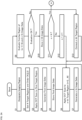
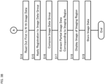
- FIGs. 3A , 3B , and 3C show examples of the operations of the ophthalmic apparatus 100.
- the operations shown in FIGs. 3B and 3C are alternatively applicable. That is, the operation shown in one of FIGs. 3B and 3C may be combined with the operation shown in FIG. 3A .
- preparatory operations such as alignment, focusing, optical path length adjustment, and polarization adjustment may be performed at arbitrary stages using known methods or techniques.
- the imaging region designating unit 204 designates an imaging region for the eye 120 (S1).
- the imaging region 310 is designated to include the optic nerve head and the macula of the fundus 300.
- the target region setting unit 205 sets target regions to include the imaging region designated in step S1, and sets an order in which OCT scanning is applied to the target regions (S2).
- N number of target regions are set.
- N is an integer equal to or greater than 2.
- the target regions are referred to as "the first target region", “the second target region”,..., “the N-th target region” according to the scan order set in step S2.
- the seven target regions 321 to 327 are set to include the imaging region 310 illustrated in FIG. 4A .
- the target regions 321 to 327 are arranged so that any two adjacent target regions partially overlap each other.
- the two adjacent target regions 322 and 323 are arranged to partially overlap each other, and the two adjacent target regions 323 and 324 are arranged to partially overlap each other.
- the scan order corresponding to the order of the reference numerals 321 to 327 is assigned to the target regions 321 to 327.
- the target region 321 is referred to as "the first target region”
- the target region 322 is referred to as "the second target region”
- the target region 327 is referred to as "the seventh target region”.
- OCT scanning is started in response to a trigger.
- the scan controlling unit 210 applies an OCT scan to the first target region among the target regions set in step S2 (S3).
- an OCT scan is applied to the first target region 321 in this stage.
- the image data generating unit 201 generates image data based on a three dimensional data set acquired from the first target region by the OCT scan in step S3 (S4).
- the image data generated is referred to as "the first image data”.
- the controlling device 126 stores the first image data generated in step S4 in a storage device (not shown in drawings) (S5).
- the storage device is typically provided in the ophthalmic apparatus 100 (e.g., provided in the controlling device 126). However, the storage device may be provided outside the ophthalmic apparatus 100.
- the scan controlling unit 210 applies an OCT scan to the target region to which the next order has been assigned (S6).
- an OCT scan is applied to the second target region.
- the present step S6 is repeatedly performed until appropriate image data is obtained from all of the target regions set in step S2.
- n 2,..., N.
- N is the number of the target regions set in step S2.
- the image data generating unit 201 generates image data based on a three dimensional data set acquired from the n-th target region by the OCT scan in step S6 (S7). This image data is referred to as "the n-th image data”.
- the controlling device 126 reads out the (n-1)-th image data and the n-th image data from the storage device, and sends them to the overlap region evaluating unit 206.
- the overlap region evaluating unit 206 executes the evaluation of the overlap regions in the (n-1)-th image data and the n-th image data (S8).
- step S8 In the event that the result of the evaluation in step S8 is good (S9: Yes), the operation proceeds to step S10. On the other hand, in the event that the result of the evaluation in step S8 is not good (S9: No), the operation proceeds to step S13. In other words, the operation proceeds to step S10 when the n-th image data (overlap region) sufficient for image data composition has been obtained, and the operation proceeds to step S13 when it has not been obtained.
- the controlling device 126 stores the n-th image data generated in step S7 in the storage device (S10).
- the controlling device 126 performs control for transferring to the processing related to the next target region (the (n+1)-th target region) (S12).
- This control includes, for example, control for changing the area to which OCT scanning is applied, such as control of the two-dimensional scanner 116 and/or control for changing the fixation position.
- the operation proceeds to step S13.
- the target region setting unit 205 corrects the n-th target region (S13).
- the target region setting unit 205 may perform the correction of the n-th target region based on the result of the evaluation in step S8.
- the n-th target region to which OCT scanning is applied later, among the (n-1)-th target region and the n-th target region as in the present example.
- the (n-1)-th target region may be changed, or both the (n-1)-th target region and the n-th target region may be changed.
- step S6 The operation returns to step S6 by the control of step S12.
- the operation of the present example proceeds to step S14 in FIG. 3B or to step S21 in FIG. 3C .
- step S11 to step S14 the controlling device 126 reads out the first to N-th image data corresponding to the first to N-th target regions from the storage device (S14).
- the controlling device 126 sends the N pieces of image data (image data group) read out, to the registration unit 202.
- the registration unit 202 applies the registration to the image data group input by the controlling device 126 (S15).
- each image data included in the image data group has an overlap region, which partly overlaps adjacent image data, appropriate for image data composition.
- each image data included in the image data group has an overlap region, which partly overlaps adjacent image data, appropriate for registration.
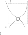
- FIG. 4C represents the image data 334 corresponding to the target region 324 shown in FIG. 4B .
- an OCT scan aims at the target region 324 and is applied to it, the region to which the OCT scan is actually applied is sometimes deviated from the intended target region 324 due to the influence of eye movement or the like.
- FIG. 4D shows the arrangement of the seven pieces of image data 331 to 337 corresponding to the seven target regions 321 to 327 shown in FIG. 4B according to the arrangement of the seven target regions 321 to 327. If the seven pieces of image data 331 to 337 are arranged in this way, that is, if the seven pieces of image data 331 to 337 are arranged without considering the influence of eye movement or the like, the image 340 of a certain tissue (the tissue image 340) is depicted in a disconnected manner, for example.
- step S15 By applying the registration in step S15, the influence of eye movement can be compensated for (or, cancelled or eliminated).
- the registration By applying the registration to the seven pieces of image data 331 to 337 shown in FIG. 4D , the relative positions of the seven pieces of image data 331 to 337 can be adjusted. This leads to the tissue image 340 being depicted in a smoothly connected manner like the actual aspect of that tissue. (See FIG. 4E ).
- the result of the registration performed in step S15 is input to the image data composing unit 203.
- the image data composing unit 203 composes the pieces of data in the image data group arranged according to the registration result (S16).
- the image data composing unit 203 composes the seven pieces of image data 331 to 337 arranged as shown in FIG. 4E . With this, the composite image data corresponding to the region of the eye 120 including the imaging region designated in step S1 is obtained.
- the image data composing unit 203 extracts partial image data corresponding to the imaging region designated in step S1, from the composite image data generated in step S16 (S17).
- the controlling device 126 displays the image of the imaging region designated in step S1 on the display device described above, based on the partial image data obtained in step S17 (S18).
- the displayed image is obtained by applying rendering to the partial image data that is three dimensional image data.
- rendering may be performed on the composite image data obtained in step S16, or on any one or more of the first to N-th image data.
- the user may designate a desired viewpoint or a desired cross section for rendering. Alternatively, a viewpoint or a cross section for rendering may be set in advance.
- the controlling device 126 may store any one or more of the following pieces of image data in a storage device not shown in drawings (S19): the partial image data obtained in step S 17; the composite image data obtained in step S 16; and the first to N-th image data.
- the storage device may be, for example, any of an element of the ophthalmic apparatus 100, a peripheral device of the ophthalmic apparatus 100, a device connectable to the ophthalmic apparatus 100 via a communication line, and a portable recording medium.
- the operation shown in FIGs. 3A and 3B is completed (End).
- step S11 the controlling device 126 reads out the first to N-th image data corresponding to the first to N-th target regions (S21) as in step S14 of FIG. 3B .
- the registration unit 202 applies the registration to the image data group input by the controlling device 126 (S22).
- the result of the registration executed in step S22 is input to the image data composing unit 203.
- the image data composing unit 203 extracts partial image data corresponding to the imaging region from each image data included in the image data group (S23). Thereby, a partial image data group corresponding to the image data group is obtained.
- the image data composing unit 203 composes the partial image data group extracted from the image data group in step S23, according to the result of the registration (S24). With this, composite image data corresponding to the imaging region designated in step S1 is obtained.
- the controlling device 126 applies rendering to the composite image data obtained in step S24 to display the image of the imaging region designated in step S1 on the aforementioned display device (S25).
- the controlling device 126 may store any one or more of the following pieces of image data in a storage device not shown in drawings (S26): the composite image data obtained in step S24; the partial image data group obtained in step S23; and the first to N-th image data.
- S26 a storage device not shown in drawings
- the target regions 321 to 327 shown in FIG. 4B are arranged in a line.
- arrangement aspects of target regions are not limited to this example.
- the target region 421 may be set at the center of the imaging region 310, and the six target regions 422 to 427 may be set around the target region 421.
- Each of the surrounding (or peripheral) target regions 422 to 427 partially overlaps the central target region 421. Further, any two target regions adjacent to each other among the surrounding target regions 422 to 427 do not overlap each other. In the case where such an arrangement is employed, the registration is applied to the combination of each of the surrounding target regions 422 to 427 and the central target region 421.
- the ophthalmic apparatus 500 illustrated in FIG. 6 includes the controlling device 510, the OCT scanner 520, the photographing device 530, and the processing device 540.
- the controlling device 510 may be configured in the same manner as the controlling device 126 of the ophthalmic apparatus 100.
- the OCT scanner 520 may be configured in the same manner as the OCT scanner 220 of the ophthalmic apparatus 100.
- the processing device 540 may be configured in the same manner as the processing device 124 of the ophthalmic apparatus 100.
- the ophthalmic apparatus 500 may be obtained by adding the photographing device 530 to the ophthalmic apparatus 100.
- the sample of the present aspect is an eye.
- description will be made with reference to the elements of the ophthalmic apparatus 100 (see FIG. 2 , etc.).
- the photographing device 530 acquires a front image by photographing the eye.
- the photographing device 530 may include a camera for photographing the eye (the fundus, the anterior eye segment, etc.) that is located (directly) in front of the eye.
- the photographing device 530 may include a camera that photographs the eye from one or more positions other than the front position, and a processor that converts the image(s) acquired by the camera into a front image.
- the ophthalmic apparatus 500 may include a communication device that receives a front image of the eye from an external device, or a reader that reads out a front image of the eye from a recording medium.
- the photographing device 530 may be a known ophthalmic modality device such as a fundus camera, a slit lamp microscope, or a surgical microscope.
- the ophthalmic apparatus 500 may execute correction of the target regions based on the front image acquired by the photographing device 530 (see step S13 in FIG. 3A for comparison).
- the processing device 540 of the present aspect may be configured to identify a partial region of the front image corresponding to a concerned target region, perform registration between the front image and image data generated based on the three dimensional data set acquired from that target region by the OCT scan, and calculate the positional difference amount of the image data with respect to the partial region.
- the controlling device 510 performs control for changing the concerned target region to compensate for the positional difference amount calculated by the processing device 540.
- the change of the target region may be, for example, any one of the followings: movement of that target region; change in the size of that target region; change in the shape of that target region; and change of the number of the target regions.
- the controlling device 510 (the scan controlling unit 210) applies another OCT scan to the target region subjected to such a change.
- infrared illumination is widely used to observe eye fundus by a motion picture without inducing miosis.
- the purposes of the use of an image obtained by infrared observation is not limited to the target region correction.
- an infrared front image may be utilized for designating an imaging region, setting target regions, setting a scan order, evaluating overlap regions, registration (the first registration), composition of image data, and the like.
- the ophthalmic apparatus 500 may be configured to display or analyze an infrared front image for any of these purposes.
- "rough (coarse)" registration may be performed with reference to the infrared front image.
- the second registration may be performed by comparing each of the plurality of pieces of image data corresponding to the target regions with the infrared front image, and identifying partial regions of the infrared front image respectively corresponding to the plurality of pieces of image data.
- the image data corresponding to each target region is three dimensional image data (typically image data defined in the XYZ coordinate system), and the infrared front image is two dimensional image data (typically image data defined in the XY coordinate system).
- the second registration may include, for example, a process of converting three dimensional image data corresponding to a target region into two dimensional image data defined in the two dimensional coordinate system in which the infrared front image is defined.
- the two dimensional image data obtained by the conversion of the three dimensional image data may be, for example, the projection image mentioned above.
- the registration between the infrared front image and the three dimensional image data may be performed using the result of the registration between the infrared front image and the projection image.
- OCT apparatuses ophthalmic apparatuses
- the ophthalmic apparatus 100 includes the OCT scanner 220 (520), the image data generating unit 201, the registration unit 202, and the image data composing unit 203.
- the OCT scanner 220 acquires three dimensional data sets from mutually different three dimensional regions of the eye 120.
- the image data generating unit 201 generates a plurality of pieces of image data from the three dimensional data sets acquired by the OCT scanner 220.
- the registration unit 202 performs the first registration between the plurality of pieces of image data generated by the image data generating unit 201, by applying image correlation calculation to each of the overlap regions in the plurality of pieces of image data.
- the image data composing unit 203 composes the plurality of pieces of image data corresponding to the mutually different three dimensional regions based on a result of the first registration performed by the registration unit 202.
- image data composition can be performed after the registration using the image correlation calculation between three dimensional image data. Therefore, composite image data corresponding to a wide region of the sample can be acquired without having to perform processing relating to landmarks as in the inventions described in US Patent No. 7,884,945 and US Patent No. 8,405,834 .
- This makes it possible to improve effective utilization of resources required for processing and shorten processing time, thereby achieving further efficiency improvement in OCT data processing. Consequently, real-time processing can be preferably performed, for example.
- the ophthalmic apparatus 100 may further include the imaging region designating unit 204 and the target region setting unit 205.
- the imaging region designating unit 204 designates an imaging region for the sample.
- the target region setting unit 205 sets target regions to include the imaging region designated by the imaging region designating unit 204.
- the OCT scanner 220 (520) is capable of sequentially applying OCT scanning to the target regions set by the target region setting unit 205, thereby acquiring three dimensional data sets corresponding to the target regions (that is, corresponding to the mutually different three dimensional regions).
- composite image data can be preferably acquired for a desired imaging region.
- the ophthalmic apparatus 100 may further include the overlap region evaluating unit 206. If this is the case, the OCT scanner 220 (520) may acquire two pieces of three dimensional data sets by applying OCT scans to two target regions among the target regions set by the target region setting unit 205.
- the image data generating unit 201 can generate two pieces of image data from the two pieces of three dimensional data sets acquired from the two target regions.
- the overlap region evaluating unit 206 evaluates the overlap regions in the two pieces of image data corresponding to the two target regions generated by the image data generating unit 201.
- the ophthalmic apparatus 100 performs the application of the first registration to at least the two pieces of image data, or the application of another OCT scan (the re-application of an OCT scan) to at least one of the two target regions, according to the result of the evaluation executed by the overlap region evaluating unit 206.
- the first registration or the re-application of the OCT scan may be performed in a selective manner together with the evaluation of the overlap regions.
- the first registration is selected in the event that the overlap regions between image data is preferable, and the re-application of the OCT scan is selected in the event that the overlap regions between image data is not preferable.
- the image data may be acquired again in the event that the overlap regions are not appropriate, and the first registration and image data composition may be performed using preferable overlap regions.
- the target region setting unit 205 may change at least one of the two target regions based on the result of the evaluation performed by the overlap region evaluating unit 206.
- the OCT scanner 220 may perform re-application of the OCT scan to the target region(s) that has been changed by the target region setting unit 205.
- the target region(s) can be adjusted before the re-application of OCT scanning. This increases the possibility of obtaining a preferable overlap region by the OCT scan in the re-application.
- the ophthalmic apparatus 500 may further include a device for preparing a front image of the sample (e.g., the photographing device 530, a communication device, a reader, etc.).
- the target region setting unit 205 may change at least one of the two target regions based on the front image.
- the OCT scanner 220 may apply another OCT scan to the target region(s) that has been changed by the target region setting unit 205.
- the target region can be adjusted before the application of another OCT scan. This increases the possibility of obtaining a preferable overlap region(s) by the another OCT scan.
- the registration unit 202 may perform the second registration between the plurality of pieces of image data based on the front image before the first registration.
- the first registration (precise, fine registration) may be performed taking the overlap regions into account after the second registration using the front image for roughly performing relative positional alignment of the plurality of pieces of image data.
- the quality of registration can be improved.
- the image data composing unit 203 may extract partial image data corresponding to the imaging region designated by the imaging region designating unit 204, from the composite image data obtained by composing the plurality of pieces of image data corresponding to the target regions.
- the reliability of acquiring image data of a desired imaging region i.e., the reliability of acquiring partial image data
- the reliability of acquiring image data of a desired imaging region i.e., the reliability of acquiring partial image data
- the image data composing unit 203 may extract a partial image data group each corresponding to the imaging region designated by the imaging region designating unit 204, from the plurality of pieces of image data respectively corresponding to the target regions, based on the result of the first registration executed by the registration unit 202.
- the image data composing unit 203 may generate composite mage data by composing the partial image data group extracted from the plurality of pieces of image data.
- the reliability of acquiring image data of a desired imaging region i.e., the reliability of acquiring partial image data
- the reliability of acquiring image data of a desired imaging region i.e., the reliability of acquiring partial image data
- the image correlation calculation performed by the registration unit 202 for the first and second image data having overlap regions may calculate at least one of the translation amount and the rotation amount between the overlap regions in the first and second image data.
- the image correlation calculation may include phase only correlation calculation.
- the positional relationship between the first and second image data can be obtained in an efficient manner owing to the utilization of image correlation (e.g., phase only correlation), without having to perform processing, like landmark detection, that requires a large amount of resources.
- image correlation e.g., phase only correlation
- the sample of the present aspect is a living eye, but an OCT apparatus used for measurement of samples other than living eyes may have the same and/or like functions and configurations.
- any of the items (functions, hardware configurations, software configurations, etc.) regarding the ophthalmic apparatus 100 (500) may be combined with an OCT apparatus of any aspect.
- the items combined yield or provide corresponding actions and effects.
- Some aspects relate to a method of controlling an OCT apparatus that includes a processor and an OCT scanner that applies an OCT scan to a sample.
- the control method may include at least the following steps: a step of controlling the OCT scanner to acquire three dimensional data sets from mutually different three dimensional regions of the sample; a step of controlling the processor to generate a plurality of pieces of image data from the three dimensional data sets; a step of controlling the processor to perform the first registration between the plurality of pieces of image data by applying an image correlation calculation to each of overlap regions in the plurality of pieces of image data; and a step of controlling the processor to compose the plurality of pieces of image data based on a result of the first registration.
- composite image data corresponding to a wide region of the sample can be acquired without having to perform processing relating to landmarks. This makes it possible to improve effective utilization of resources required for processing and shorten processing time, thereby achieving further efficiency improvement in OCT data processing. Consequently, real-time processing can be preferably performed, for example.
- any of the items (functions, hardware configurations, software configurations, etc.) regarding the ophthalmic apparatus 100 (500) may be combined with the control method of the present aspect.
- the items combined yield or provide corresponding actions and effects.
- Some aspects relate to a program that causes a computer to execute such a control method of an OCT apparatus. Any of the items described regarding the ophthalmic apparatus 100 (500) may be combined with the program. Further, some aspects relate to a computer-readable non-transitory recording medium storing such a program. Any of the items described regarding the ophthalmic apparatus 100 (500) may be combined with the recording medium.
- the ophthalmic apparatus 100 (500) functions as an OCT data processing apparatus that processes data acquired by OCT scanning.
- the ophthalmic apparatus 100 (500) includes the OCT scanner 220 (520) as an element of performing OCT scanning; however, the OCT data processing apparatus may not include such an OCT scanning element.
- the OCT data processing apparatus includes a receiving unit that includes the communication device and/or the reader described above and receives three dimensional data sets acquired from mutually different three dimensional regions of a sample from the outside.
- the image data generating unit 201 generates a plurality of pieces of image data from the three dimensional data sets received from the outside by the receiving unit.
- the registration unit 202 performs the first registration between the plurality of pieces of image data, by applying an image correlation calculation to each of the overlap regions in the plurality of pieces of image data generated by the image data generating unit 201.
- the image data composing unit 203 composes the plurality of pieces of image data based on a result of the first registration executed by the registration unit 202.
- composite image data corresponding to a wide region of the sample can be acquired without having to perform processing relating to landmarks. This makes it possible to improve effective utilization of resources required for processing and shorten processing time, thereby achieving further efficiency improvement in OCT data processing. Consequently, real-time processing can be preferably performed, for example.
- any of the items (functions, hardware configurations, software configurations, etc.) regarding the ophthalmic apparatus 100 may be combined with the control method of the present aspect.
- the items combined yield or provide corresponding actions and effects.
- Some aspects relate to a program that causes a computer to execute such a control method of an OCT data processing apparatus. Any of the items described regarding the ophthalmic apparatus 100 (500) may be combined with the program. Further, some aspects relate to a computer-readable non-transitory recording medium storing such a program. Any of the items described regarding the ophthalmic apparatus 100 (500) may be combined with the recording medium.
- Some aspects of an OCT apparatus e.g., the ophthalmic apparatus 100 or 500
- some aspects of a method of controlling an OCT apparatus some aspects of an OCT data processing apparatus, or some aspects of a method of controlling an OCT data processing apparatus provide an imaging method using OCT.
- the OCT imaging method of some aspects may include at least the following steps: a step of acquiring three dimensional data sets from mutually different three dimensional regions of a sample; a step of generating a plurality of pieces of image data from the three dimensional data sets; a step of performing the first registration between the plurality of pieces of image data by applying an image correlation calculation to each of the overlap regions in the plurality of pieces of image data; and composing the plurality of pieces of image data based on a result of the first registration.
- any of the items (functions, hardware configurations, software configurations, etc.) regarding the ophthalmic apparatus 100 (500) may be combined with the OCT imaging method of the present aspect.
- the items combined yield or provide corresponding actions and effects.
- Some aspects relate to a program that causes a computer to execute such an OCT imaging method. Any of the items described regarding the ophthalmic apparatus 100 (500) may be combined with the program. Further, some aspects relate to a computer-readable non-transitory recording medium storing such a program. Any of the items described regarding the ophthalmic apparatus 100 (500) may be combined with the recording medium.
- Some aspects of an OCT apparatus e.g., the ophthalmic apparatus 100 or 500
- some aspects of a method of controlling an OCT apparatus some aspects of an OCT data processing apparatus, or some aspects of a method of controlling an OCT data processing apparatus provide a method of processing OCT data.
- the OCT data processing method of some aspects may include at least the following steps: a step of preparing three dimensional data sets acquired from mutually different three dimensional regions of a sample; a step of generating a plurality of pieces of image data from the three dimensional data sets; a step of performing the first registration between the plurality of pieces of image data by applying an image correlation calculation to each of the overlap regions in the plurality of pieces of image data; and a step of composing the plurality of pieces of image data based on a result of the first registration.
- any of the items (functions, hardware configurations, software configurations, etc.) regarding the ophthalmic apparatus 100 (500) may be combined with the OCT data processing method of the present aspect.
- the items combined yield or provide corresponding actions and effects.
- Some aspects relate to a program that causes a computer to execute such an OCT data processing method. Any of the items described regarding the ophthalmic apparatus 100 (500) may be combined with the program. Further, some aspects relate to a computer-readable non-transitory recording medium storing such a program. Any of the items described regarding the ophthalmic apparatus 100 (500) may be combined with the recording medium.
- the non-transitory recording medium may be in any form, and examples thereof include a magnetic disk, an optical disk, a magneto-optical disk, a semiconductor memory, and the like.
Landscapes
- Health & Medical Sciences (AREA)
- Life Sciences & Earth Sciences (AREA)
- Engineering & Computer Science (AREA)
- Physics & Mathematics (AREA)
- General Physics & Mathematics (AREA)
- General Health & Medical Sciences (AREA)
- Biomedical Technology (AREA)
- Biophysics (AREA)
- Heart & Thoracic Surgery (AREA)
- Medical Informatics (AREA)
- Molecular Biology (AREA)
- Surgery (AREA)
- Animal Behavior & Ethology (AREA)
- Public Health (AREA)
- Veterinary Medicine (AREA)
- Radiology & Medical Imaging (AREA)
- Nuclear Medicine, Radiotherapy & Molecular Imaging (AREA)
- Ophthalmology & Optometry (AREA)
- Theoretical Computer Science (AREA)
- Signal Processing (AREA)
- Pathology (AREA)
- Computer Vision & Pattern Recognition (AREA)
- Eye Examination Apparatus (AREA)
- Investigating Or Analysing Materials By Optical Means (AREA)
Claims (8)
- Verfahren zur Bildgebung mithilfe von optischer Kohärenztomographie, OCT, das Folgendes umfasst:Erfassen mehrerer dreidimensionaler Datensätze aus mehreren dreidimensionalen Regionen einer Probe, die sich voneinander unterscheiden,Erzeugen mehrerer Bilddatenstücke aus den mehreren dreidimensionalen Datensätzen,Durchführen einer ersten Registrierung zwischen den mehreren Bilddatenstücken durch Anwenden einer Bildkorrelationsberechnung auf jede von mehreren Überschneidungsregionen in den mehreren Bilddatenstücken undZusammenstellen der mehreren Bilddatenstücke auf der Grundlage eines Ergebnisses der ersten Registrierung,wobei das Verfahren ferner Folgendes umfasst:Bestimmen einer Bildgebungsregion in der Probe undderartiges Einstellen mehrerer Zielregionen, dass sie die Bildgebungsregion enthalten, wobeidie mehreren dreidimensionalen Datensätze durch aufeinanderfolgendes Anwenden eines OCT-Scans auf die mehreren Zielregionen erfasst werden,wobei das Verfahren Folgendes umfasst:Erfassen von zweien der mehreren dreidimensionalen Datensätze durch aufeinanderfolgendes Anwenden eines OCT-Scans auf zwei der mehreren Zielregionen, Erzeugen von zweien der mehreren Bilddatenstücke aus den zwei dreidimensionalen Datensätzen,gekennzeichnet durchEvaluieren einer Überschneidungsregion der beiden Bilddatenstücke undje nach Ergebnis der Evaluierung Auswählen und Durchführen:- eines Anwendens der ersten Registrierung auf zumindest die zwei Bilddatenstücke oder- eines Anwendens eines weiteren OCT-Scans auf zumindest eine der beiden Zielregionen,wobei das Erfassen von zwei dreidimensionalen Datensätzen, das Erzeugen von zwei Bilddatenstücken, das Evaluieren einer Überschneidungsregion und das Anwenden der ersten Registrierung oder eines weiteren OCT-Scans auf mindestens eine der beiden Zielregionen wiederholt wird, bis alle der mehreren Bilddatenstücke erzeugt sind.
- OCT-Bildgebungsverfahren nach Anspruch 1, das ferner das Ändern mindestens einer der beiden Zielregionen auf der Grundlage des Ergebnisses der Evaluierung umfasst, wobei
der weitere OCT-Scan auf eine geänderte Zielregion angewendet wird. - OCT-Bildgebungsverfahren nach Anspruch 1, das ferner Folgendes umfasst:Vorbereiten einer Vorderansicht der Probe undÄndern mindestens einer der beiden Zielregionen auf der Grundlage der Vorderansicht, wobeider weitere OCT-Scan auf eine geänderte Zielregion angewendet wird.
- OCT-Bildgebungsverfahren nach Anspruch 1, das ferner das Extrahieren von der Bildgebungsregion entsprechenden Teilbilddaten aus zusammengesetzten Bilddaten umfasst, die durch Zusammensetzen der mehreren Bilddatenstücke erhalten werden.
- OCT-Bildgebungsverfahren nach Anspruch 1, das ferner das Extrahieren einer der Bildgebungsregion entsprechenden Teilbilddatengruppe aus den mehreren Bilddatenstücken auf der Grundlage des Ergebnisses der ersten Registrierung und das Zusammensetzen der Teilbilddatengruppe umfasst.
- OCT-Bildgebungsverfahren nach Anspruch 1, wobei die Bildkorrelationsberechnung für erste und zweite Bilddaten, die einander überschneidende Regionen enthalten, einen Translations- und/oder einen Rotationsbetrag zwischen der Überschneidungsregion in den ersten Bilddaten und der Überschneidungsregion in den zweiten Bilddaten berechnet.
- OCT-Bildgebungsverfahren nach Anspruch 6, wobei die Bildkorrelationsberechnung eine nur die Phase betreffende Korrelationsberechnung umfasst.
- OCT-Bildgebungsverfahren nach Anspruch 1, wobei das Evaluieren der Überschneidungsregion einen Vergleich mit einem voreingestellten Schwellenwert umfasst, wobei ein gutes Evaluierungsergebnis erhalten wird,- wenn eine Größe der Überschneidungsregion mindestens dem Schwellenwert entspricht oder- wenn ein Bildkorrelationswert mindestens dem Schwellenwert entspricht oder- wenn ein Betrag einer relativen Bewegung aus einer voreingestellten Positionsbeziehung zwischen den beiden Bilddatenstücken unter dem Schwellenwert liegt.
Applications Claiming Priority (3)
| Application Number | Priority Date | Filing Date | Title |
|---|---|---|---|
| JP2019123437A JP7409793B2 (ja) | 2019-07-02 | 2019-07-02 | 光コヒーレンストモグラフィ(oct)装置の作動方法、octデータ処理装置の作動方法、oct装置、octデータ処理装置 |
| JP2019123431A JP2021007665A (ja) | 2019-07-02 | 2019-07-02 | 光コヒーレンストモグラフィ(oct)データ処理方法、oct装置、その制御方法、octデータ処理装置、その制御方法、プログラム、及び、記録媒体 |
| JP2019129315A JP7308679B2 (ja) | 2019-07-11 | 2019-07-11 | 光コヒーレンストモグラフィ(oct)イメージング方法 |
Publications (3)
| Publication Number | Publication Date |
|---|---|
| EP3760968A2 EP3760968A2 (de) | 2021-01-06 |
| EP3760968A3 EP3760968A3 (de) | 2021-04-28 |
| EP3760968B1 true EP3760968B1 (de) | 2024-09-04 |
Family
ID=71143626
Family Applications (4)
| Application Number | Title | Priority Date | Filing Date |
|---|---|---|---|
| EP20182152.7A Active EP3760968B1 (de) | 2019-07-02 | 2020-06-25 | Verfahren zur oct-bildgebung |
| EP21200117.6A Pending EP3961147A1 (de) | 2019-07-02 | 2020-06-25 | Verfahren zur verarbeitung von daten der optischen kohärenztomografie (oct) |
| EP20182150.1A Pending EP3760967A3 (de) | 2019-07-02 | 2020-06-25 | Verfahren zur verarbeitung von daten der optischen kohärenztomografie (oct) |
| EP20182149.3A Active EP3760966B1 (de) | 2019-07-02 | 2020-06-25 | Verfahren zur bildgebung durch optische kohärenztomografie (oct) und verfahren zur verarbeitung von oct-daten |
Family Applications After (3)
| Application Number | Title | Priority Date | Filing Date |
|---|---|---|---|
| EP21200117.6A Pending EP3961147A1 (de) | 2019-07-02 | 2020-06-25 | Verfahren zur verarbeitung von daten der optischen kohärenztomografie (oct) |
| EP20182150.1A Pending EP3760967A3 (de) | 2019-07-02 | 2020-06-25 | Verfahren zur verarbeitung von daten der optischen kohärenztomografie (oct) |
| EP20182149.3A Active EP3760966B1 (de) | 2019-07-02 | 2020-06-25 | Verfahren zur bildgebung durch optische kohärenztomografie (oct) und verfahren zur verarbeitung von oct-daten |
Country Status (2)
| Country | Link |
|---|---|
| US (4) | US11375892B2 (de) |
| EP (4) | EP3760968B1 (de) |
Families Citing this family (3)
| Publication number | Priority date | Publication date | Assignee | Title |
|---|---|---|---|---|
| JP7491096B2 (ja) * | 2020-07-03 | 2024-05-28 | 株式会社ニデック | 眼科情報解析装置および眼科情報解析プログラム |
| JP7853292B2 (ja) * | 2020-10-23 | 2026-04-28 | ジェネンテック, インコーポレイテッド | マルチモーダル地図状萎縮病変セグメンテーション |
| WO2025231051A1 (en) * | 2024-05-03 | 2025-11-06 | Topcon Corporation | Method and apparatus for acquiring ophthalmic image data and identifying disease |
Family Cites Families (38)
| Publication number | Priority date | Publication date | Assignee | Title |
|---|---|---|---|---|
| US6044181A (en) * | 1997-08-01 | 2000-03-28 | Microsoft Corporation | Focal length estimation method and apparatus for construction of panoramic mosaic images |
| US6434265B1 (en) * | 1998-09-25 | 2002-08-13 | Apple Computers, Inc. | Aligning rectilinear images in 3D through projective registration and calibration |
| US7301644B2 (en) * | 2004-12-02 | 2007-11-27 | University Of Miami | Enhanced optical coherence tomography for anatomical mapping |
| WO2006078802A1 (en) | 2005-01-21 | 2006-07-27 | Massachusetts Institute Of Technology | Methods and apparatus for optical coherence tomography scanning |
| JP4916779B2 (ja) * | 2005-09-29 | 2012-04-18 | 株式会社トプコン | 眼底観察装置 |
| US7768652B2 (en) * | 2006-03-16 | 2010-08-03 | Carl Zeiss Meditec, Inc. | Methods for mapping tissue with optical coherence tomography data |
| US20130003077A1 (en) * | 2010-03-31 | 2013-01-03 | Canon Kabushiki Kaisha | Tomographic imaging apparatus and control apparatus for tomographic imaging apparatus |
| US8396269B2 (en) * | 2010-04-08 | 2013-03-12 | Digital Pathco LLC | Image quality assessment including comparison of overlapped margins |
| JP5735790B2 (ja) | 2010-12-02 | 2015-06-17 | 株式会社ニデック | 眼科撮影装置 |
| JP5236089B1 (ja) * | 2012-01-26 | 2013-07-17 | キヤノン株式会社 | 光干渉断層撮像装置、光干渉断層撮像装置の制御方法、およびプログラム |
| JP6115007B2 (ja) | 2012-01-31 | 2017-04-19 | 株式会社ニデック | 眼科画像処理装置及びプログラム |
| EP2633804B1 (de) | 2012-03-02 | 2017-12-06 | Nidek Co., Ltd | Ophthalmologische Fotografiervorrichtung |
| JP6007517B2 (ja) | 2012-03-02 | 2016-10-12 | 株式会社ニデック | 眼科撮影装置 |
| US9016862B2 (en) * | 2012-05-10 | 2015-04-28 | Sonomed Ip Holdings, Inc. | Multimodality correlation of optical coherence tomography using secondary reference images |
| EP2929327B1 (de) * | 2012-12-05 | 2019-08-14 | Perimeter Medical Imaging, Inc. | System und verfahren für oct-bildgebung mit breitem feld |
| JP6184114B2 (ja) * | 2013-01-31 | 2017-08-23 | キヤノン株式会社 | 光干渉断層撮像装置およびその制御方法 |
| US20140293289A1 (en) | 2013-03-27 | 2014-10-02 | Kabushiki Kaisha Topcon | Method for Generating Two-Dimensional Images From Three-Dimensional Optical Coherence Tomography Interferogram Data |
| US9295387B2 (en) * | 2013-04-03 | 2016-03-29 | Kabushiki Kaisha Topcon | Ophthalmologic apparatus |
| US10268885B2 (en) * | 2013-04-15 | 2019-04-23 | Microsoft Technology Licensing, Llc | Extracting true color from a color and infrared sensor |
| JP6415030B2 (ja) * | 2013-08-07 | 2018-10-31 | キヤノン株式会社 | 画像処理装置、画像処理方法及びプログラム |
| JP6276943B2 (ja) * | 2013-08-28 | 2018-02-07 | 株式会社トプコン | 眼科装置 |
| JP6463047B2 (ja) * | 2014-09-05 | 2019-01-30 | キヤノン株式会社 | 眼科装置及び眼科装置の作動方法 |
| JP6719891B2 (ja) * | 2015-01-07 | 2020-07-08 | キヤノン株式会社 | 画像処理装置及び画像処理方法 |
| US20170004344A1 (en) * | 2015-07-02 | 2017-01-05 | Canon Kabushiki Kaisha | Robust Eye Tracking for Scanning Laser Ophthalmoscope |
| JP6580448B2 (ja) | 2015-10-16 | 2019-09-25 | 株式会社トプコン | 眼科撮影装置及び眼科情報処理装置 |
| JP6624945B2 (ja) * | 2016-01-21 | 2019-12-25 | キヤノン株式会社 | 画像形成方法及び装置 |
| US11452442B2 (en) * | 2016-06-15 | 2022-09-27 | Oregon Health & Science University | Systems and methods for automated widefield optical coherence tomography angiography |
| JP6307141B2 (ja) | 2016-11-10 | 2018-04-04 | キヤノン株式会社 | 眼科装置、眼科システム、眼科装置の制御方法およびプログラム |
| JP2018117693A (ja) | 2017-01-23 | 2018-08-02 | 株式会社トプコン | 眼科装置 |
| WO2018175654A1 (en) * | 2017-03-23 | 2018-09-27 | Doheny Eye Institute | Systems, methods, and devices for optical coherence tomgraphy multiple enface angiography averaging |
| JP6776189B2 (ja) | 2017-06-26 | 2020-10-28 | 株式会社トプコン | 眼科装置、及びその制御方法 |
| JP6472495B2 (ja) | 2017-08-09 | 2019-02-20 | キヤノン株式会社 | 眼科装置および制御方法 |
| JP2019041841A (ja) | 2017-08-30 | 2019-03-22 | 株式会社トプコン | 眼科装置、及びその制御方法 |
| US11000187B2 (en) * | 2017-09-07 | 2021-05-11 | Carl Zeiss Meditec, Inc. | Systems and methods for improved montaging of ophthalmic imaging data |
| JP2018023818A (ja) | 2017-10-13 | 2018-02-15 | 株式会社トプコン | 眼科観察装置 |
| US10681267B2 (en) * | 2017-12-28 | 2020-06-09 | Facebook, Inc. | Systems and methods for increasing resolution of images captured by a camera sensor |
| US10560641B2 (en) * | 2017-12-28 | 2020-02-11 | Facebook, Inc. | Systems and methods for generating a bias for a camera sensor for increasing resolution of captured images |
| JP7677885B2 (ja) * | 2018-11-21 | 2025-05-15 | ユニバーシティ オブ ワシントン | 遠隔眼科学における網膜テンプレート合致のためのシステムおよび方法 |
-
2020
- 2020-06-25 EP EP20182152.7A patent/EP3760968B1/de active Active
- 2020-06-25 EP EP21200117.6A patent/EP3961147A1/de active Pending
- 2020-06-25 EP EP20182150.1A patent/EP3760967A3/de active Pending
- 2020-06-25 EP EP20182149.3A patent/EP3760966B1/de active Active
- 2020-06-30 US US16/916,154 patent/US11375892B2/en active Active
- 2020-07-01 US US16/917,925 patent/US11849996B2/en active Active
- 2020-07-01 US US16/917,922 patent/US11229355B2/en active Active
-
2023
- 2023-10-11 US US18/378,711 patent/US12226160B2/en active Active
Also Published As
| Publication number | Publication date |
|---|---|
| US20210004971A1 (en) | 2021-01-07 |
| EP3760966B1 (de) | 2024-06-26 |
| US20210003383A1 (en) | 2021-01-07 |
| EP3760968A3 (de) | 2021-04-28 |
| EP3760968A2 (de) | 2021-01-06 |
| EP3760967A3 (de) | 2021-04-07 |
| US11375892B2 (en) | 2022-07-05 |
| EP3760967A2 (de) | 2021-01-06 |
| EP3961147A1 (de) | 2022-03-02 |
| US11849996B2 (en) | 2023-12-26 |
| EP3760966A1 (de) | 2021-01-06 |
| US20210000338A1 (en) | 2021-01-07 |
| US20240041316A1 (en) | 2024-02-08 |
| US11229355B2 (en) | 2022-01-25 |
| US12226160B2 (en) | 2025-02-18 |
Similar Documents
| Publication | Publication Date | Title |
|---|---|---|
| US12226160B2 (en) | Method of processing optical coherence tomography (OCT) data, method of OCT imaging, and OCT data processing apparatus | |
| JP6746960B2 (ja) | 眼科用レーザ治療装置 | |
| JP6987522B2 (ja) | 画像生成装置、画像生成方法、及びプログラム | |
| EP3449807B1 (de) | Ophthalmologische vorrichtung und verfahren zur steuerung davon | |
| JP7104516B2 (ja) | 断層画像撮影装置 | |
| JP2019088382A (ja) | 画像処理装置、眼科撮影装置、画像処理方法、及びプログラム | |
| EP3430975A1 (de) | Ophthalmische vorrichtung | |
| US20220386864A1 (en) | Oct apparatus and non-transitory computer-readable storage medium | |
| US12256994B2 (en) | Systems and methods for combining fundus images of an eye | |
| JP7824386B2 (ja) | 眼科装置、その制御方法、プログラム、及び記録媒体 | |
| JP2021062077A (ja) | 眼科装置 | |
| JP7019128B2 (ja) | 光断層画像撮影装置 | |
| JP2025113303A (ja) | 光コヒーレンストモグラフィ(oct)データ処理方法 | |
| EP3628212B1 (de) | Ophthalmische bildgebungsvorrichtung, steuerungsverfahren dafür, ophthalmisches bildgebungsverfahren und aufzeichnungsmedium | |
| JP7308679B2 (ja) | 光コヒーレンストモグラフィ(oct)イメージング方法 | |
| JP2021090631A (ja) | 画像処理方法、走査型イメージング方法、画像処理装置、その制御方法、走査型イメージング装置、その制御方法、プログラム、及び記録媒体 | |
| JP7409793B2 (ja) | 光コヒーレンストモグラフィ(oct)装置の作動方法、octデータ処理装置の作動方法、oct装置、octデータ処理装置 | |
| JP7317582B2 (ja) | 眼科装置及び眼科装置の制御方法 | |
| JP7024240B2 (ja) | 眼科システムおよび眼科システム制御プログラム | |
| JP6936676B2 (ja) | 眼科装置 | |
| JP2024146325A (ja) | 医療画像処理装置、oct装置、および医療画像処理プログラム |
Legal Events
| Date | Code | Title | Description |
|---|---|---|---|
| PUAI | Public reference made under article 153(3) epc to a published international application that has entered the european phase |
Free format text: ORIGINAL CODE: 0009012 |
|
| STAA | Information on the status of an ep patent application or granted ep patent |
Free format text: STATUS: REQUEST FOR EXAMINATION WAS MADE |
|
| 17P | Request for examination filed |
Effective date: 20200723 |
|
| AK | Designated contracting states |
Kind code of ref document: A2 Designated state(s): AL AT BE BG CH CY CZ DE DK EE ES FI FR GB GR HR HU IE IS IT LI LT LU LV MC MK MT NL NO PL PT RO RS SE SI SK SM TR |
|
| AX | Request for extension of the european patent |
Extension state: BA ME |
|
| PUAL | Search report despatched |
Free format text: ORIGINAL CODE: 0009013 |
|
| AK | Designated contracting states |
Kind code of ref document: A3 Designated state(s): AL AT BE BG CH CY CZ DE DK EE ES FI FR GB GR HR HU IE IS IT LI LT LU LV MC MK MT NL NO PL PT RO RS SE SI SK SM TR |
|
| AX | Request for extension of the european patent |
Extension state: BA ME |
|
| RIC1 | Information provided on ipc code assigned before grant |
Ipc: G01B 9/02 20060101AFI20210322BHEP Ipc: A61B 3/10 20060101ALI20210322BHEP |
|
| STAA | Information on the status of an ep patent application or granted ep patent |
Free format text: STATUS: EXAMINATION IS IN PROGRESS |
|
| 17Q | First examination report despatched |
Effective date: 20230131 |
|
| GRAP | Despatch of communication of intention to grant a patent |
Free format text: ORIGINAL CODE: EPIDOSNIGR1 |
|
| STAA | Information on the status of an ep patent application or granted ep patent |
Free format text: STATUS: GRANT OF PATENT IS INTENDED |
|
| RIC1 | Information provided on ipc code assigned before grant |
Ipc: A61B 3/00 20060101ALI20240415BHEP Ipc: G01B 9/02091 20220101ALI20240415BHEP Ipc: G01B 9/02055 20220101ALI20240415BHEP Ipc: A61B 3/10 20060101ALI20240415BHEP Ipc: G01B 9/02 20060101AFI20240415BHEP |
|
| INTG | Intention to grant announced |
Effective date: 20240429 |
|
| GRAS | Grant fee paid |
Free format text: ORIGINAL CODE: EPIDOSNIGR3 |
|
| GRAA | (expected) grant |
Free format text: ORIGINAL CODE: 0009210 |
|
| STAA | Information on the status of an ep patent application or granted ep patent |
Free format text: STATUS: THE PATENT HAS BEEN GRANTED |
|
| AK | Designated contracting states |
Kind code of ref document: B1 Designated state(s): AL AT BE BG CH CY CZ DE DK EE ES FI FR GB GR HR HU IE IS IT LI LT LU LV MC MK MT NL NO PL PT RO RS SE SI SK SM TR |
|
| REG | Reference to a national code |
Ref country code: GB Ref legal event code: FG4D |
|
| REG | Reference to a national code |
Ref country code: CH Ref legal event code: EP |
|
| REG | Reference to a national code |
Ref country code: IE Ref legal event code: FG4D |
|
| REG | Reference to a national code |
Ref country code: DE Ref legal event code: R096 Ref document number: 602020036929 Country of ref document: DE |
|
| REG | Reference to a national code |
Ref country code: LT Ref legal event code: MG9D |
|
| REG | Reference to a national code |
Ref country code: NL Ref legal event code: MP Effective date: 20240904 |
|
| PG25 | Lapsed in a contracting state [announced via postgrant information from national office to epo] |
Ref country code: NO Free format text: LAPSE BECAUSE OF FAILURE TO SUBMIT A TRANSLATION OF THE DESCRIPTION OR TO PAY THE FEE WITHIN THE PRESCRIBED TIME-LIMIT Effective date: 20241204 |
|
| PG25 | Lapsed in a contracting state [announced via postgrant information from national office to epo] |
Ref country code: GR Free format text: LAPSE BECAUSE OF FAILURE TO SUBMIT A TRANSLATION OF THE DESCRIPTION OR TO PAY THE FEE WITHIN THE PRESCRIBED TIME-LIMIT Effective date: 20241205 Ref country code: PL Free format text: LAPSE BECAUSE OF FAILURE TO SUBMIT A TRANSLATION OF THE DESCRIPTION OR TO PAY THE FEE WITHIN THE PRESCRIBED TIME-LIMIT Effective date: 20240904 Ref country code: FI Free format text: LAPSE BECAUSE OF FAILURE TO SUBMIT A TRANSLATION OF THE DESCRIPTION OR TO PAY THE FEE WITHIN THE PRESCRIBED TIME-LIMIT Effective date: 20240904 |
|
| PG25 | Lapsed in a contracting state [announced via postgrant information from national office to epo] |
Ref country code: BG Free format text: LAPSE BECAUSE OF FAILURE TO SUBMIT A TRANSLATION OF THE DESCRIPTION OR TO PAY THE FEE WITHIN THE PRESCRIBED TIME-LIMIT Effective date: 20240904 |
|
| PG25 | Lapsed in a contracting state [announced via postgrant information from national office to epo] |
Ref country code: LV Free format text: LAPSE BECAUSE OF FAILURE TO SUBMIT A TRANSLATION OF THE DESCRIPTION OR TO PAY THE FEE WITHIN THE PRESCRIBED TIME-LIMIT Effective date: 20240904 |
|
| PG25 | Lapsed in a contracting state [announced via postgrant information from national office to epo] |
Ref country code: HR Free format text: LAPSE BECAUSE OF FAILURE TO SUBMIT A TRANSLATION OF THE DESCRIPTION OR TO PAY THE FEE WITHIN THE PRESCRIBED TIME-LIMIT Effective date: 20240904 |
|
| PG25 | Lapsed in a contracting state [announced via postgrant information from national office to epo] |
Ref country code: ES Free format text: LAPSE BECAUSE OF FAILURE TO SUBMIT A TRANSLATION OF THE DESCRIPTION OR TO PAY THE FEE WITHIN THE PRESCRIBED TIME-LIMIT Effective date: 20240904 Ref country code: RS Free format text: LAPSE BECAUSE OF FAILURE TO SUBMIT A TRANSLATION OF THE DESCRIPTION OR TO PAY THE FEE WITHIN THE PRESCRIBED TIME-LIMIT Effective date: 20241204 |
|
| PG25 | Lapsed in a contracting state [announced via postgrant information from national office to epo] |
Ref country code: RS Free format text: LAPSE BECAUSE OF FAILURE TO SUBMIT A TRANSLATION OF THE DESCRIPTION OR TO PAY THE FEE WITHIN THE PRESCRIBED TIME-LIMIT Effective date: 20241204 Ref country code: PL Free format text: LAPSE BECAUSE OF FAILURE TO SUBMIT A TRANSLATION OF THE DESCRIPTION OR TO PAY THE FEE WITHIN THE PRESCRIBED TIME-LIMIT Effective date: 20240904 Ref country code: NO Free format text: LAPSE BECAUSE OF FAILURE TO SUBMIT A TRANSLATION OF THE DESCRIPTION OR TO PAY THE FEE WITHIN THE PRESCRIBED TIME-LIMIT Effective date: 20241204 Ref country code: LV Free format text: LAPSE BECAUSE OF FAILURE TO SUBMIT A TRANSLATION OF THE DESCRIPTION OR TO PAY THE FEE WITHIN THE PRESCRIBED TIME-LIMIT Effective date: 20240904 Ref country code: HR Free format text: LAPSE BECAUSE OF FAILURE TO SUBMIT A TRANSLATION OF THE DESCRIPTION OR TO PAY THE FEE WITHIN THE PRESCRIBED TIME-LIMIT Effective date: 20240904 Ref country code: GR Free format text: LAPSE BECAUSE OF FAILURE TO SUBMIT A TRANSLATION OF THE DESCRIPTION OR TO PAY THE FEE WITHIN THE PRESCRIBED TIME-LIMIT Effective date: 20241205 Ref country code: FI Free format text: LAPSE BECAUSE OF FAILURE TO SUBMIT A TRANSLATION OF THE DESCRIPTION OR TO PAY THE FEE WITHIN THE PRESCRIBED TIME-LIMIT Effective date: 20240904 Ref country code: ES Free format text: LAPSE BECAUSE OF FAILURE TO SUBMIT A TRANSLATION OF THE DESCRIPTION OR TO PAY THE FEE WITHIN THE PRESCRIBED TIME-LIMIT Effective date: 20240904 Ref country code: BG Free format text: LAPSE BECAUSE OF FAILURE TO SUBMIT A TRANSLATION OF THE DESCRIPTION OR TO PAY THE FEE WITHIN THE PRESCRIBED TIME-LIMIT Effective date: 20240904 |
|
| REG | Reference to a national code |
Ref country code: AT Ref legal event code: MK05 Ref document number: 1720789 Country of ref document: AT Kind code of ref document: T Effective date: 20240904 |
|
| PG25 | Lapsed in a contracting state [announced via postgrant information from national office to epo] |
Ref country code: NL Free format text: LAPSE BECAUSE OF FAILURE TO SUBMIT A TRANSLATION OF THE DESCRIPTION OR TO PAY THE FEE WITHIN THE PRESCRIBED TIME-LIMIT Effective date: 20240904 |
|
| PG25 | Lapsed in a contracting state [announced via postgrant information from national office to epo] |
Ref country code: IS Free format text: LAPSE BECAUSE OF FAILURE TO SUBMIT A TRANSLATION OF THE DESCRIPTION OR TO PAY THE FEE WITHIN THE PRESCRIBED TIME-LIMIT Effective date: 20250104 Ref country code: PT Free format text: LAPSE BECAUSE OF FAILURE TO SUBMIT A TRANSLATION OF THE DESCRIPTION OR TO PAY THE FEE WITHIN THE PRESCRIBED TIME-LIMIT Effective date: 20250106 |
|
| PG25 | Lapsed in a contracting state [announced via postgrant information from national office to epo] |
Ref country code: RO Free format text: LAPSE BECAUSE OF FAILURE TO SUBMIT A TRANSLATION OF THE DESCRIPTION OR TO PAY THE FEE WITHIN THE PRESCRIBED TIME-LIMIT Effective date: 20240904 Ref country code: SM Free format text: LAPSE BECAUSE OF FAILURE TO SUBMIT A TRANSLATION OF THE DESCRIPTION OR TO PAY THE FEE WITHIN THE PRESCRIBED TIME-LIMIT Effective date: 20240904 |
|
| PG25 | Lapsed in a contracting state [announced via postgrant information from national office to epo] |
Ref country code: EE Free format text: LAPSE BECAUSE OF FAILURE TO SUBMIT A TRANSLATION OF THE DESCRIPTION OR TO PAY THE FEE WITHIN THE PRESCRIBED TIME-LIMIT Effective date: 20240904 Ref country code: AT Free format text: LAPSE BECAUSE OF FAILURE TO SUBMIT A TRANSLATION OF THE DESCRIPTION OR TO PAY THE FEE WITHIN THE PRESCRIBED TIME-LIMIT Effective date: 20240904 |
|
| PG25 | Lapsed in a contracting state [announced via postgrant information from national office to epo] |
Ref country code: CZ Free format text: LAPSE BECAUSE OF FAILURE TO SUBMIT A TRANSLATION OF THE DESCRIPTION OR TO PAY THE FEE WITHIN THE PRESCRIBED TIME-LIMIT Effective date: 20240904 |
|
| PG25 | Lapsed in a contracting state [announced via postgrant information from national office to epo] |
Ref country code: SK Free format text: LAPSE BECAUSE OF FAILURE TO SUBMIT A TRANSLATION OF THE DESCRIPTION OR TO PAY THE FEE WITHIN THE PRESCRIBED TIME-LIMIT Effective date: 20240904 Ref country code: IT Free format text: LAPSE BECAUSE OF FAILURE TO SUBMIT A TRANSLATION OF THE DESCRIPTION OR TO PAY THE FEE WITHIN THE PRESCRIBED TIME-LIMIT Effective date: 20240904 |
|
| REG | Reference to a national code |
Ref country code: DE Ref legal event code: R097 Ref document number: 602020036929 Country of ref document: DE |
|
| PGFP | Annual fee paid to national office [announced via postgrant information from national office to epo] |
Ref country code: DE Payment date: 20250429 Year of fee payment: 6 |
|
| PG25 | Lapsed in a contracting state [announced via postgrant information from national office to epo] |
Ref country code: DK Free format text: LAPSE BECAUSE OF FAILURE TO SUBMIT A TRANSLATION OF THE DESCRIPTION OR TO PAY THE FEE WITHIN THE PRESCRIBED TIME-LIMIT Effective date: 20240904 |
|
| PLBE | No opposition filed within time limit |
Free format text: ORIGINAL CODE: 0009261 |
|
| STAA | Information on the status of an ep patent application or granted ep patent |
Free format text: STATUS: NO OPPOSITION FILED WITHIN TIME LIMIT |
|
| PGFP | Annual fee paid to national office [announced via postgrant information from national office to epo] |
Ref country code: FR Payment date: 20250508 Year of fee payment: 6 |
|
| 26N | No opposition filed |
Effective date: 20250605 |
|
| PG25 | Lapsed in a contracting state [announced via postgrant information from national office to epo] |
Ref country code: SE Free format text: LAPSE BECAUSE OF FAILURE TO SUBMIT A TRANSLATION OF THE DESCRIPTION OR TO PAY THE FEE WITHIN THE PRESCRIBED TIME-LIMIT Effective date: 20240904 |
|
| REG | Reference to a national code |
Ref country code: CH Ref legal event code: H13 Free format text: ST27 STATUS EVENT CODE: U-0-0-H10-H13 (AS PROVIDED BY THE NATIONAL OFFICE) Effective date: 20260127 |
|
| PG25 | Lapsed in a contracting state [announced via postgrant information from national office to epo] |
Ref country code: MC Free format text: LAPSE BECAUSE OF FAILURE TO SUBMIT A TRANSLATION OF THE DESCRIPTION OR TO PAY THE FEE WITHIN THE PRESCRIBED TIME-LIMIT Effective date: 20240904 |
|
| PG25 | Lapsed in a contracting state [announced via postgrant information from national office to epo] |
Ref country code: LU Free format text: LAPSE BECAUSE OF NON-PAYMENT OF DUE FEES Effective date: 20250625 |
|
| GBPC | Gb: european patent ceased through non-payment of renewal fee |
Effective date: 20250625 |
|
| REG | Reference to a national code |
Ref country code: BE Ref legal event code: MM Effective date: 20250630 |
|
| PG25 | Lapsed in a contracting state [announced via postgrant information from national office to epo] |
Ref country code: GB Free format text: LAPSE BECAUSE OF NON-PAYMENT OF DUE FEES Effective date: 20250625 |
|
| PG25 | Lapsed in a contracting state [announced via postgrant information from national office to epo] |
Ref country code: IE Free format text: LAPSE BECAUSE OF NON-PAYMENT OF DUE FEES Effective date: 20250625 |
|
| PG25 | Lapsed in a contracting state [announced via postgrant information from national office to epo] |
Ref country code: BE Free format text: LAPSE BECAUSE OF NON-PAYMENT OF DUE FEES Effective date: 20250630 |
|
| PG25 | Lapsed in a contracting state [announced via postgrant information from national office to epo] |
Ref country code: CH Free format text: LAPSE BECAUSE OF NON-PAYMENT OF DUE FEES Effective date: 20250630 |