EP3760995A1 - Dispositif de mesure de pression - Google Patents
Dispositif de mesure de pression Download PDFInfo
- Publication number
- EP3760995A1 EP3760995A1 EP20181568.5A EP20181568A EP3760995A1 EP 3760995 A1 EP3760995 A1 EP 3760995A1 EP 20181568 A EP20181568 A EP 20181568A EP 3760995 A1 EP3760995 A1 EP 3760995A1
- Authority
- EP
- European Patent Office
- Prior art keywords
- pressure
- measuring device
- pressure measuring
- pressure measurement
- values
- Prior art date
- Legal status (The legal status is an assumption and is not a legal conclusion. Google has not performed a legal analysis and makes no representation as to the accuracy of the status listed.)
- Granted
Links
Images


Classifications
-
- G—PHYSICS
- G01—MEASURING; TESTING
- G01L—MEASURING FORCE, STRESS, TORQUE, WORK, MECHANICAL POWER, MECHANICAL EFFICIENCY, OR FLUID PRESSURE
- G01L21/00—Vacuum gauges
- G01L21/16—Vacuum gauges by measuring variation of frictional resistance of gases
- G01L21/24—Vacuum gauges by measuring variation of frictional resistance of gases using rotating members; Vacuum gauges of the Langmuir type
-
- G—PHYSICS
- G01—MEASURING; TESTING
- G01L—MEASURING FORCE, STRESS, TORQUE, WORK, MECHANICAL POWER, MECHANICAL EFFICIENCY, OR FLUID PRESSURE
- G01L21/00—Vacuum gauges
- G01L21/10—Vacuum gauges by measuring variations in the heat conductivity of the medium, the pressure of which is to be measured
- G01L21/12—Vacuum gauges by measuring variations in the heat conductivity of the medium, the pressure of which is to be measured measuring changes in electric resistance of measuring members, e.g. of filaments; Vacuum gauges of the Pirani type
-
- G—PHYSICS
- G01—MEASURING; TESTING
- G01L—MEASURING FORCE, STRESS, TORQUE, WORK, MECHANICAL POWER, MECHANICAL EFFICIENCY, OR FLUID PRESSURE
- G01L21/00—Vacuum gauges
- G01L21/30—Vacuum gauges by making use of ionisation effects
-
- G—PHYSICS
- G01—MEASURING; TESTING
- G01L—MEASURING FORCE, STRESS, TORQUE, WORK, MECHANICAL POWER, MECHANICAL EFFICIENCY, OR FLUID PRESSURE
- G01L27/00—Testing or calibrating of apparatus for measuring fluid pressure
- G01L27/002—Calibrating, i.e. establishing true relation between transducer output value and value to be measured, zeroing, linearising or span error determination
- G01L27/005—Apparatus for calibrating pressure sensors
Definitions
- the present invention relates first of all to a pressure measuring device and a processing system with such a pressure measuring device.
- the invention also relates to a method for measuring pressure by means of a pressure measuring device.
- the present invention is located in the field of vacuum process measurement and / or regulation, but is not restricted to it.
- a vacuum range is used between the air pressure of the atmosphere of around 1000 hPa and an extreme ultra-high vacuum of 10-14 hPa.
- Air is a gas mixture that consists of many particles in the form of atoms and molecules. These particles are in constant motion. If they hit somewhere, they exert a force there.
- the pressure or vacuum measurement is defined by determining a unit of area and measuring the number and intensity of these impacts on this area. Measurements are necessary in order to set defined conditions and to control and test processes. For this reason, vacuum gauges generally need to be “calibrated” (not primary standards). This means that individual measuring devices with the same function must be adjusted in such a way that they deliver the same measurement results under the same conditions within the specifications of each measurement method. There are various technical devices that are essential for applications in industry and research in order to evaluate or measure the vacuum medium.
- Vacuum technology as such has been known for a long time. In practice, different methods are available for measuring the pressure conditions in a vacuum, which differ significantly in their application properties. Vacuum can be divided into different areas.
- Rough vacuum (GV) describes a pressure range between ambient pressure and 1 mbar.
- Fine vacuum (FV) describes the range between 1 mbar and 10 -3 mbar.
- High vacuum (HV) means the range between 10 -3 mbar and 10 -8 mbar.
- Ultra-high vacuum (UHV) is the range between 10 -8 mbar and 10 -13 mbar.
- the object of the present invention is to carry out a measurement in wide pressure ranges with the most accurate, reproducible and long-term stable pressure measurement values possible.
- the present invention is initially directed to a pressure measuring device.
- the invention is not limited to the measurement of specific pressure areas and the size of specific pressure measurement values.
- a pressure measuring device is in particular a device by means of which a pressure, in particular the pressure conditions, is determined, for example measured or determined.
- the pressure measuring device has a number of different components, which are explained in the further course of the description.
- the pressure measuring device of the present invention can be designed or implemented in different ways.
- the pressure measuring device is designed in the form of a physical entity.
- An entity is to be understood as a unit.
- a physical entity represents a physical unit. All components thus represent internal components with respect to the pressure measuring device. This means in particular that all components are arranged or formed within a housing.
- the pressure measuring device is designed partly in the form of a physical entity and partly in the form of a functional entity.
- a functional entity is characterized in particular by the fact that the components are spatially separated from one another and the unit results from the functional interaction of the individual components. In this case, only a subgroup of the components is internal components in the sense of the first preferred embodiment. At least one component of the pressure measuring device is designed as an external component.
- the pressure measuring device is designed as a purely functional entity. This means that all components are each designed as independent, spatially separated components.
- the individual components for realizing the pressure measuring device are functionally connected to one another in a suitable manner.
- the pressure measuring device is designed as a vacuum pressure measuring device.
- the pressure measuring device preferably interacts with a processing system. That is, the pressure measuring device works with the Machining system together.
- the pressure measuring device is an independent, separate entity compared to the processing system, which works together with the processing system.
- the pressure measuring device is only partially an independent, separate entity compared to the processing system.
- At least individual components of the pressure measuring device are, in particular integral, constituent parts of the processing system and are arranged or formed on or in the processing system. However, these last-mentioned components interact with the first-mentioned components for the purpose of realizing the pressure measuring device.
- all components of the pressure measuring device, in particular integral parts of the processing system are, however, functionally cooperating to implement the pressure measuring device. Preferred exemplary embodiments of the various embodiments are described in greater detail in the further course of the description, in particular also in connection with the figures in the description of the figures.
- a processing system is in particular a system for manufacturing and / or handling and / or processing and / or for examining and / or for determining properties of workpieces.
- at least individual processing steps are carried out under or at a certain pressure, preferably in at least one Process chamber.
- a certain pressure preferably in at least one Process chamber.
- precise knowledge of the prevailing, actual pressure value is required.
- the pressure measuring device according to the invention is used in this context.
- the present invention is not limited to specific types of processing systems. Some examples of this are explained in more detail in the further course of the description.
- the processing system is designed as a vacuum processing system.
- a vacuum processing system preferably has at least one vacuum processing chamber on.
- precise knowledge of the vacuum value actually present is required.
- the basic idea of the present invention consists in particular in using two different pressure measurement methods with different pressure measurement devices, which have different properties, the measurements of the two pressure measurement devices preferably running at least largely parallel and the measurements of the two pressure measurement devices combined, preferably in an overlap and / or superposition to be brought.
- a pressure measuring device which has the features of independent patent claim 1.
- the pressure measuring device has a first pressure measuring device.
- the first pressure measuring device is configured to provide first measured pressure values.
- provision of measured pressure values is understood to mean that the measured pressure values are determined directly, for example measured, by the pressure measuring device, but also that the measured pressure values are determined indirectly, for example calculated, derived or the like.
- the first pressure measuring device is characterized by high accuracy and / or long-term stability.
- the first pressure measuring device is therefore designed as a pressure measuring device for high-precision and / or long-term stable pressure measurement.
- the first pressure measuring device is a gas friction manometer or a spinning rotor-gauge sensor device, which is also referred to for short in the context of the description as an SRG sensor device.
- the gas friction manometer has a rotating ball.
- a gas friction manometer basically works as follows: A ball is supported without friction in a magnetic field. An external rotating field ( ⁇ 400 Hz) drives the ball, sets the ball in rotation and causes the ball to rotate. Then the drive is switched off. The ball is braked by the friction in the residual gas. The decrease in the speed of rotation is measured with scanning coils and the particle density of the gas is determined. The deceleration rate can be measured directly as a measure of density or pressure. With this method, only the global properties of the sphere are included in the measurement and are stored with a factor (calibration factor), the rest of the arrangement is not variable or error-prone.
- the measured pressure values provided by the gas friction manometer are preferably provided in the form of electrical signals.
- the gas friction manometer enables a measuring method that is characterized by its high accuracy (1% of the measured value) and a wide (> 6 decades) measuring range that extends into the high vacuum range (HV) (> 10 to 1x10 -7 hPa).
- the pressure measuring device has a very simple structure with a rotating ball as a sensor, works without contact, without penetrations into the vacuum or mechanically stressed components. All information and interactions take place via magnetic and electromagnetic forces in the vacuum.
- the gas friction manometer therefore has no electrically or mechanically loaded components and achieves a correspondingly high long-term stability (drift ⁇ 1% / year), is also robust and corrosion-resistant, for example made of all metal.
- the process is far less influenced by temperature, aging or coating effects. Due to the accuracy in high vacuum and the long-term stability, the gas friction manometer is used in many calibration laboratories as a transfer standard.
- the first pressure measuring device interacts with a second pressure measuring device, which is designed as a faster and / or continuous pressure measuring device compared to the first pressure measuring device.
- the pressure measuring device therefore has a second pressure measuring device, which is designed as a faster and / or continuous pressure measuring device compared to the first pressure measuring device.
- the second pressure measuring device is configured to provide second pressure measurement values.
- the second pressure measuring device is part of a pressure measuring device designed as a physical entity.
- both the first and the second pressure measuring device are preferably combined physically into a single entity.
- both the first pressure measuring device and the second Pressure measuring device can be arranged in a housing.
- the pressure measurement values provided by the first and second pressure measurement devices are processed in the pressure measurement device embodied as a physical entity, that is to say unit. This can take place, for example, in a control device as explained in more detail below.
- the two pressure measuring devices are not physically located within a single physical entity, but only the first pressure measuring device.
- the second pressure measuring device is then located outside it and can, for example, be part of a processing system and be arranged or formed on or in the processing system.
- the pressure measuring device preferably has an interface which is configured to receive measured pressure values from the second pressure measuring device.
- the pressure measurement values provided by the second pressure measurement device are read into the pressure measurement device, for example in a control device described below, via the interface.
- the second pressure measuring device can be any other pressure measuring device of a processing system.
- the measured pressure values provided by the second pressure measuring device are transmitted via the interface and processed further at a suitable point within the pressure measuring device.
- the second pressure measuring device is again not part of a physical entity of the pressure measuring device.
- the second pressure measuring device is still read by the processing system, for example by its system control, and the processing system uses the recorded second pressure measurement values of the second pressure measuring device itself to carry out the pressure measurement according to the invention.
- the term “configure” is understood in particular to mean that a component is designed for a specific function.
- the second pressure measuring device is preferably characterized by speed and / or continuous measurements.
- the second pressure measuring device is therefore preferably designed as a pressure measuring device for rapid and / or continuous pressure measurement.
- the present invention is not limited to specific embodiments for the second pressure measuring device. Some preferred, but not exclusive, exemplary embodiments are explained in more detail in the further course of the description.
- the first pressure measuring device and the second pressure measuring device are preferably arranged in a common measuring space or assigned to a common measuring space.
- the measuring room is preferably the process chamber of a processing system.
- the pressure measuring device has a control device which is provided in such a way that it is able to relate the first pressure measurement values provided by the first pressure measurement device and the second pressure measurement values provided by the second pressure measurement device to one another. Preferred embodiments of such a control device are explained in more detail in the further course of the description.
- the control device has a calibration device. Preferred embodiments of such a calibration device are explained in more detail in the further course of the description.
- the calibration device is provided in such a way that it is able to calibrate and optionally adjust the second pressure measurement values provided by the second pressure measurement device by means of the first pressure measurement values provided by the first pressure measurement device, and / or those provided by the first pressure measurement device first pressure readings by means of the second pressure measurement device provided second pressure measurement values, in particular continuously, to calibrate and optionally to adjust.
- the first and second measured pressure values are preferably not mixed.
- the signal, i.e. the second pressure measurement value, of the second pressure measurement device is calibrated or recalibrated and optionally adjusted, preferably continuously, by means of the signal, i.e. the first pressure measurement value, of the first pressure measurement device.
- the properties of the second pressure measuring device for example its speed, can be retained.
- the positive properties of the first pressure measuring device are also used, for example its accuracy and / or stability.
- the calibration device is therefore preferably provided in such a way that it is able to carry out a, preferably in-situ, calibration of the second pressure measuring device by means of the first pressure measuring device in a, preferably cyclical, process.
- a, preferably in-situ, calibration of the second pressure measuring device by means of the first pressure measuring device in a, preferably cyclical, process.
- the pressure measuring device is preferably configured, ie designed, to relate to one another, that is to say in particular to bring them into connection with one another, in particular to combine, pressure measurement values that are provided by the first pressure measuring device and the second pressure measuring device.
- the combination of the pressure measuring devices or the combination of the pressure measured values of the two pressure measuring devices to form a signal can be implemented in various ways.
- the pressure measuring device is designed such that the measurements of the first and second pressure measuring devices run at least largely parallel.
- the pressure measuring device is designed such that the measurements of the first and second pressure measuring devices are made to overlap and / or superimpose.
- the calibration device preferably has suitable combination means, overlapping means or superimposing means. For the design and functioning of such means At this point, reference is also made in full to the statements relating to the method according to the invention.
- the further measuring range can also be used advantageously for setting the second pressure measuring device (zero point setting).
- the pressure measuring device of the present invention in its entirety is preferably a combination pressure measuring device in which the pressure measured values of the two pressure measuring devices, which are preferably in the form of signals or are converted into signals, for example by software, are preferably combined into one signal.
- the second pressure measuring device preferably always leads. If, for example, there is no pressure change so that a steady pressure is present, the signal from the second pressure measuring device carries, while the first, slow pressure measuring device determines an accurate first pressure measurement value in the form of an accurate signal and optionally stores it in a memory device. When the pressure changes, which in turn is determined by the second pressure measuring device, the exact signal from the first pressure measuring device is transmitted to the second pressure measured value in accordance with internal specifications, and this is calibrated. If the value is approached again, it is more precise, and the calibration curve of the imprecise and less stable measuring method is increased or reduced to the true state.
- the second measured pressure values of the second pressure measuring device are calibrated and optionally adjusted by means of the first measured pressure values of the first pressure measuring device. If the pressure range of the second pressure measuring device is more suitable, the calibration and, if necessary, adjustment can also be carried out in reverse order, alternatively or additionally in a different embodiment. This is described in more detail below in connection with the calibration process. If there is a change in pressure, the fast signal from the second pressure measuring device also leads. If the pressure is constant again, the signal from the second pressure measuring device is again carried, and the first device measures again in the background, and if the pressure changes, the second signal is recalibrated. In other words: the signal of the second pressure measuring device is calibrated, preferably repeatedly, by the signal from the first pressure measuring device, and preferably brought to the correct, otherwise never attainable accuracy value of 1% of the measured value between 10 and 1x10 -7 mbar.
- the present invention in particular realizes a unique measurement in wide ranges, in particular for vacuum process measurement and / or regulation / control.
- a uniquely accurate, long-term stable and yet fast measurement over approximately 9 decades in the HV (10 to 10 -7 mbar) can be realized.
- the solution according to the invention is characterized by fast response times (high to low: minutes-seconds / low to high: two-digit ms). There is a unique accuracy of up to 1% of the measured value in the 10 -4 to 1x10 -7 range.
- the useful range of capacitive process manometers for example, can be extended by at least two decades.
- the solution according to the invention is relatively insensitive to temperature and contamination. Under suitable conditions, a high long-term stability (of up to years) can be achieved, not in days / weeks.
- the solution according to the invention allows dynamic, rapid measurement in the vacuum range (10 to 5x10 -7 mbar).
- the pressure measuring device can be switched on from time to time. Or it can preferably be run in continuous operation.
- the invention is not restricted to specific types of the second pressure measuring devices. Some preferred exemplary embodiments are described below.
- the second pressure measuring device is designed as a heat conduction vacuum meter, in particular as a Pirani vacuum meter.
- ionizing or capacitive systems can also supply the second pressure value as a second measuring method.
- Heat conduction vacuum gauges are already known from the prior art and basically work as follows: A wire in the recipient is heated by the current through a measuring bridge. It cools down by conduction of the gas molecules to the wall of the recipient. The temperature-dependent resistance of the wire is given in measured by the measuring bridge. The heat conduction can be calculated from resistance and heating current. The heat conduction is proportional to the particle density and free path and is therefore independent of the pressure.
- the thermal conduction vacuum gauge uses the linear relationship between thermal conductivity and pressure of a gas.
- the core of this pressure measuring device is a current-carrying wire (filament), which is usually made of tungsten. It releases the heat generated in it to the surrounding gas. If the gas pressure is reduced, less heat can be dissipated, which would increase the temperature of the wire and thus its resistance.
- the wire is connected as a branch of a Wheatstone bridge. The heating voltage on this bridge is regulated in such a way that the resistance and thus the temperature of the measuring wire is constant regardless of the heat dissipation.
- the heat conduction vacuum gauge measures the pressure indirectly via the particle number density. Since this depends on the type of particle, the pressure measurement depends on the type of gas.
- the pressure scale is usually based on nitrogen; the pressure read is referred to as the "nitrogen equivalent pressure".
- the second pressure measuring device can also be designed in a different way.
- the second pressure measuring device must, however, be designed in such a way that it meets the criteria described above in comparison to the first pressure measuring device.
- a number of exemplary embodiments for the second pressure measuring device are described below.
- the second pressure measuring device can be a direct pressure measuring device.
- the pressure (p) is physically the result of a force (F) acting on a surface (A).
- the most direct pressure measurement method would therefore be to determine a force acting on a given surface.
- This is implemented, for example, with the piston manometer, with its weight-loaded piston with a defined cross-sectional area.
- Liquid manometers in which the pressure only depends on the height (h) and the density (Q) of the liquid column, are also called Immediate pressure gauges viewed.
- (g) is the acceleration due to gravity. ⁇ indicates the use of difference quantities.
- liquid manometers U-tube manometers, McLeod manometers, etc.
- liquid manometers U-tube manometers, McLeod manometers, etc.
- the indirect pressure measuring devices also include pressure gauges with a spring-elastic measuring element.
- Various types of metallic springs are used in spring pressure gauges to measure pressure. The calibration is carried out using liquid manometers.
- the advantages of spring pressure gauges are their low cost and their insensitivity to environmental influences.
- Bourdon tube pressure gauges, diaphragm pressure gauges and capsule pressure gauges They differ fundamentally in the shape of the spring used.
- the second pressure measuring device can be an absolute and differential pressure measuring device.
- pressure measuring devices with a spring-elastic measuring element are mostly used for measuring absolute and differential pressure.
- the atmospheric air pressure on the measuring spring must be replaced by a vacuum. So the inside of the capsule spring is evacuated in an aneroid barometer, so that the air pressure acting from the outside deforms the membranes. If the housing of a Bourdon tube pressure gauge is evacuated, an absolute pressure measuring device is also obtained.
- a diaphragm pressure gauge the side of the diaphragm facing away from the measuring pressure must be evacuated. Diaphragm measuring systems are mostly used for differential pressure measurement.
- the two diaphragm springs are hydraulically coupled via a filling medium.
- the resilient corrugated pipes ensure that the two pressure chambers are sealed against the atmosphere.
- the two sealing elements provide overload protection: As soon as one side of the differential pressure manometer is overloaded, they safely shut off the pressure chamber from the atmosphere.
- the second pressure measuring device can be a piezoresistive pressure measuring device.
- the piezoresistive pressure measuring devices are based on the technology of the Wheatstone measuring bridge.
- the resulting change in resistance can be converted by the microchip integrated in the sensor into the physical quantity pressure.
- the highly sensitive piezoresistive sensor element is located in a diaphragm seal, which is intended to prevent the measuring medium from penetrating the pressure measuring element.
- the measuring system is filled with a liquid (e.g. silicone oil, glycerine or white oil).
- the silicon membrane transfers the pressure to the liquid and this transfers the said pressure to the pressure measuring device.
- the second pressure measuring device can be a capacitive pressure measuring device (CM).
- CM capacitive pressure measuring device
- the capacitance change of a capacitor is used in the capacitive pressure measurement.
- the deflection of the deformable capacitor plate results in a change in the distance between the two capacitor plates.
- the capacitance changes reciprocally to the plate distance and thus to the deflection of the capacitor plate on the one Force works.
- the change in capacitance can be linearized and thus provides usable information that can be transformed into pressure via the ASIC.
- Both methods indirectly use the stream of ions generated from the gas as a measured variable for the pressure.
- energy in the form of heat and voltage (hot wire / filament - hot cathode HC) or high voltage (magnetic field / cold cathode CC) must be transferred into the system. Both the hot filaments and the generated and accelerated ions are reactive and lead to changes in the system (oxidation, sputtering).
- a cold cathode ionization pressure measuring device basically works as follows: A DC voltage of around 2 kV is applied between the anode and the cathode. Existing electrons are accelerated in this field and ionize residual gas particles through impact ionization. A pressure-dependent discharge current is formed which is measured. Above 10 -2 mbar, the ion flow changes into a glow discharge, which is independent of the pressure (upper measuring range limit). Ions that impact either stick to the cathode and are neutralized there, or they knock out material (cathode sputtering). The material is deposited on the walls of the measuring rooms. This process slowly consumes the cathode and is therefore usually designed to be replaceable.
- the Penning vacuum meter is based on residual gas ionization using cold cathodes.
- the neutralization of the ions leads to a measurable (electron) current, which is based on the ion current and therefore depends on the particle number density in the residual gas.
- the Bayard-Alpert vacuum meter for example, is based on residual gas ionization using hot cathodes.
- the pressure measuring device has a control device which configures, that is to say designed, for processing and relating to one another, in particular for combining and / or overlapping and / or superimposing the pressure measurement values provided by the first and second pressure measuring device.
- the control device is a signal processing device, or the control device has at least one device for signal processing.
- the control device for example have electrical and / or logic components which are combined in a suitable manner to form a circuit.
- the control device preferably has a processor device in which a computer program product runs which, when executed, processes the pressure measurement values provided by the two pressure measurement devices.
- control device can be designed as one or more components and / or placed at different locations.
- the control device can be part of a pressure measuring device embodied as a physical entity and, for example, be arranged or embodied in a corresponding housing.
- the control device can be designed in several parts, with part of the control device being assigned to the physical entity of the pressure measuring device, while at least one other part of the control device is located outside it and is arranged or formed, for example, in the system control of a processing system.
- the control device can only be part of the system control of a processing system.
- the pressure measuring device in particular the control device, preferably has an interface to a system control of a processing system, the interface being configured, that is to say designed, for transmitting signals between the pressure measuring device, in particular its control device, and the system control.
- This makes it possible to make the signals generated in the pressure measuring device available to a system control of a processing system, where they are used to control a processing system, for example.
- the control device has a calibration device which is provided in such a way that it is able to calibrate the second pressure measurement device, in particular the pressure measurement values provided by the second pressure measurement device, on the basis of pressure measurement values from the first pressure measurement device, and / or vice versa.
- the calibration device preferably has a processor unit, the calibration preferably by means of a suitable Program means takes place, for example by means of a suitable computer program product. “Calibration” is understood to mean, in particular, the determination and documentation of a deviation of the second pressure measuring device, in particular the measured pressure values provided by the second pressure measuring device, from the correct value of the measured variable, that is to say of the pressure.
- the calibration device can also be designed to adjust the corresponding measured pressure values after they have been calibrated. While a deviation in the measured pressure values is determined in particular by means of the calibration, the measured pressure values are changed and / or adapted by means of the adjustment process. This procedure allows the pressure measurement values provided by the second pressure measurement device to be recalibrated and optionally adjusted, preferably continuously, or vice versa, using the first pressure measurement values provided by the first pressure measurement device.
- the second pressure measuring device in particular the measured pressure values provided by the second pressure measuring device, is / are preferably calibrated and optionally adjusted by the first pressure measuring device, in particular by the measured pressure values provided by the first pressure measuring device.
- the pressure measurement values provided by the second pressure measurement device are compared with the first pressure measurement values provided by the first pressure measurement device.
- the first measured pressure values serve as the reference signal. If a discrepancy between the second measured pressure values and the first measured pressure values is recognized or determined, the second measured pressure values are adapted to the first measured pressure values. This can be done for example by means of the program means mentioned above.
- the calibration process is described in greater detail below in connection with the method according to the invention, so that at this point reference is made in full to these corresponding statements below.
- the control device preferably has a device for generating electrical signals on the basis of the measured pressure values provided by the first and / or second pressure measuring device. These electrical signals can then be passed on to the system control of a vacuum processing system. If the measured pressure values provided by the pressure measuring device (s) are already electrical signals, such a device can of course be omitted.
- the pressure measuring device in particular its control device, represents a so-called measured value transmitter in these cases.
- the pressure measuring device for example its control device, receives the pressure measured values from the first and / or second pressure measuring device (s) and converts them into electrical signals, for example by means of conversion. Or, the pressure readings are already supplied as electrical signals.
- the pressure measuring device in particular its control device, takes on the function of a so-called “transducer”, for example.
- control device can have a memory device or an interface to such a memory device.
- the measured pressure values provided by the first and / or second pressure measuring device are at least temporarily stored in the memory device.
- the pressure measuring device is preferably configured, that is to say designed, for the in-situ determination of a process pressure in a processing installation.
- the pressure measuring device can be arranged on the processing system or placed next to the processing system.
- the pressure measuring device preferably has a housing, the individual components being arranged within the housing. At least individual components of the pressure measuring device can also be integrated in the processing system in a different configuration.
- a processing system which has at least one process chamber and at least one system controller and also at least one pressure measuring device according to the first aspect of the invention. For this reason, reference is made and referred to in full at this point to the statements on the first aspect of the invention and to the general description of the invention above.
- the invention is not restricted to specific types of processing systems. Some preferred embodiments of this are explained in more detail below.
- the processing system is preferably a vacuum processing system.
- the system control preferably has at least one interface to the pressure measuring device.
- This interface is configured or designed for the exchange of signals between the system control and the pressure measuring device.
- the signals emanating from the pressure measuring device, in particular from its control device, which are present in particular as electrical signals, can be used after being received in the system control to control the processing system.
- the vacuum pressure measuring device, in particular its control device can be part of the system control.
- the processing system is described below in the context of a preferred embodiment in the form of a vacuum processing system in the field of semiconductor production. It goes without saying that the invention is not restricted to this particular embodiment.
- the processing system is preferably designed as a vacuum processing system in the field of semiconductor production.
- Semiconductor technology in particular is characterized by ever smaller structure sizes and ever more complex components.
- the elements should be able to be produced defect-free on the smallest possible area (Zero Defect Strategy).
- the processing should take place on wafers that are as large as possible and possibly as thin as possible. Wafers are about a millimeter thick disks made from semiconductor blanks and mostly made of silicon. In order to manufacture modern processors, they have to go through hundreds of process steps, many of them in FV and HV with the monitoring of one of the most important process variables - pressure.
- CM capacitive pressure sensors
- the widely used capacitive manometers (CM) are based on the direct measurement of the pressure (p) as a proportional force (K) on a constant area (A).
- the deflection (x) membrane is measured capacitively in relation to a counter electrode. The membrane is part of the capacitor / bridge circuit and the change in distance is converted into an electrical signal.
- CMs for process control are used in many semiconductor processes and are brought onto the market in >> 10,000 quantities every year (PVD, Dry-Etch, CVD, Diffusion, etc.). Below a pressure range of approx. ⁇ 10 -3 hPa, however, effects such as the change in the ambient temperature or the coating of the membrane ( ⁇ m range) begin to influence the measurement result, which is expressed in the application in the progress of the signal (drift).
- a pressure measuring device in particular in the form of a vacuum pressure measuring device, can now advantageously also be used for such or in such semiconductor manufacturing plants.
- a highly accurate and long-term stable, but slow and discontinuous pressure measurement method using a first pressure measuring device namely using a gas friction manometer or an SRG sensor device
- a highly accurate and long-term stable AND fast and continuous measuring method is converted into a highly accurate and long-term stable AND fast and continuous measuring method.
- This is achieved by combining the measuring signal of this first pressure measuring device with the measuring signal of a second pressure measuring device, which is preferably a simple sensor, whereby the second pressure measuring device should have a dynamic (a characteristic) in the measuring range of the first pressure measuring device and should be fast means quasi continuously, measures.
- the method for pressure measurement is preferably embodied in a processing system, in particular a processing system according to the second aspect of the invention.
- a processing system in particular a processing system according to the second aspect of the invention.
- the measured pressure values are preferably recorded by the first pressure measuring device and by the second pressure measuring device in parallel or almost in parallel.
- the pressure measurement values detected by the first pressure measuring device and by the second pressure measuring device are preferably brought into overlap and / or superimposition.
- a method for pressure measurement in particular using a pressure measuring device according to the first aspect of the invention, is provided, which is characterized in that pressure measurements are carried out by means of a first pressure measuring device, that pressure measurements are carried out with a second pressure measuring device, that the measurements / measuring ranges of the first and second pressure measuring device in particular run at least largely parallel and / or in particular overlapping in wide areas, and that the measuring areas of the first pressure measuring device and the second pressure measuring device are combined, in particular brought into overlap and / or superimposition in one signal, but possibly also the further measuring range of the one, in particular the first pressure measuring device, is advantageously used for setting the other, in particular the second pressure measuring device (zero point setting).
- the second pressure measuring device always leads in the pressure measuring method.
- the second pressure measurement values provided by the second pressure measurement device are calibrated and optionally adjusted by means of the first pressure measurement values provided by the first pressure measurement device, in particular continuously stationary pressure is determined, the pressure is determined on the basis of the first pressure measurement values determined by the first pressure measuring device and optionally stored in a memory device.
- a stationary that is to say constant pressure
- the signal of the second pressure measuring device consequently leads, while the first, slow, pressure measuring device determines and optionally stores an accurate pressure measuring signal.
- the second pressure measurement values of the second pressure measurement device are calibrated and optionally adjusted based on the first pressure measurement values determined by the first pressure measurement device and optionally stored. If the pressure changes, at which the signal from the second pressure measuring device continues to lead, the exact pressure measuring signal of the first pressure measuring device is transferred to the second pressure measuring signal of the second pressure measuring device, in particular according to internal specifications, and this is calibrated, optionally with an adjustment. If this pressure value is approached again, it is now more precise. The calibration curve of the more imprecise and less stable second pressure measurement method is thus raised or lowered to the true pressure value.
- the first pressure measuring device determines the exact pressure and optionally stores it in the memory device. Only when the pressure changes or changes, which the second pressure measuring device also detects, is the second measured pressure value of the second pressure measuring device calibrated and optionally adjusted or readjusted. This process is preferably repeated, and takes place in particular at different pressures, so that a single-point calibration results in multiple calibration, even at different pressures. The system is getting more accurate all the time. For example, drifts in the second pressure measurement method are compensated for.
- a second pressure measuring device for example a simple but fast pressure measuring device measuring in parallel.
- measured values with high accuracy and long-term stability can also be made available for dynamic production processes.
- the pressure values are output digitally or analogously, preferably according to the internal software-based calculation.
- the first pressure measuring device, the precise gas friction manometer can in future calibrate and optionally adjust the second pressure measuring device, for example a fast Pirani.
- a fundamental feature of the present invention is to provide for the first time a pressure measuring device that can be used for process control up to a high vacuum (typically: 1 to approx. 1x10 -7 hPa) and all previously known methods with regard to accuracy, long-term reproducibility, robustness, speed, dynamics and exceeds measuring range ⁇ 10 -3 hPa.
- the second pressure measuring device is made of a corrosion-resistant material, for example all metal, which is the case with some CMs, this also results in a measuring method that measures once down to the HV, with a corrosion resistance that allows the use of Piranies, HC and CC made difficult or impossible so far.
- the present invention thus also closes an application-limited gap in the pressure range up to typically 1x10 -7 mbar
- the positive properties such as accuracy, Reproducibility, high dynamics and a sensibly usable signal up to the high vacuum range (1x10 -7 hPa) are retained.
- the range of application of the solution according to the invention can be expanded into many process applications, e.g. the semiconductor industry, which up to now has relied on capacitive pressure sensors (CM, p min > 10 -4 hPa) and, in the pressure range below, on ionizing processes such as hot cathodes (HC, p min > 10 -12 hPa) or cold cathode (CC, p min > 10 -12 hPa).
- CM capacitive pressure sensors
- HC hot cathodes
- CC cold cathode
- p min are only specifications, most systems for process applications achieve a base pressure of 10 -5 to 10 -7 hPa.
- the invention also enables use in the HV area in which CC, HC and Piranies cannot be used due to corrosion or coating.
- the advantages of the technology according to the invention are in particular that the outstanding properties of a transfer standard can be transferred to process applications.
- users benefit from increased process reliability and increased resource efficiency, because this reduces the material scrap in the production process, e.g. in the semiconductor industry, as well as the manufacturing costs and, as a result, higher product margins can be achieved.
- a basic feature of the present invention is the combination of two pressure measuring devices which measure in parallel and which differ completely in their time constants.
- the measuring intervals may have to be adjusted dynamically.
- CMs With CMs, a) and b) lead to a drift or a fluctuation of the signal in the last decade of the measuring range and can no longer be distinguished from changes in the process.
- CM in the pressure range below 10 -3 hPa is strongly influenced by temperature influences.
- these are less important (root T absolute), especially since one is still in one optimal measurement window moves while the CMs are at their physical resolution limit.
- the present invention is not limited to use in such semiconductor processes.
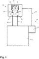
- a processing system 10 is shown in schematic form, which has a process chamber 11 and a system control 12.
- the processing system 10 is, for example, a vacuum processing system, which has at least one vacuum process chamber.
- the processing system 10 also has a pressure measuring device 20 which is designed for in-situ operation.
- the pressure measuring device 20 is, for example, a vacuum pressure measuring device.
- the pressure measuring device 20 has a housing 27 in which the individual components are arranged.
- the pressure measuring device 20 has a first pressure measuring device 21 in the form of a gas friction manometer, which is connected to the process chamber 11 via a line 22 in the form of a pressure connection.
- the pressure measuring device 20 has a control device 24 which has a calibration device 25, optionally a device for generating an electrical signal on the basis of pressure measurement values and / or an amplifier device for amplifying the pressure measurement signals provided.
- the control device 24 has a memory device 32 in which at least temporarily measured pressure values of the first pressure measuring device 21 are stored.
- the first pressure measuring device 21 is connected to the control device 24 via a line 23. Via this line 23, which is a signal transmission line, measured pressure values provided by the first pressure measurement device 21 are transmitted to the control device 24.
- the vacuum pressure measuring device 20 has a second pressure measuring device 28, which is designed, for example, in the form of a heat conduction vacuum gauge.
- the second pressure measuring device 28 is also connected to the process chamber 11 via a line 29 in the form of a pressure connection.
- the second pressure measuring device 28 is also connected to the control device 24 via a line 30. Via this line 30, measured pressure values provided by the second pressure measurement device 28 are transmitted to the control device 24.
- the measured pressure values are processed in the control device 24.
- the electrical signals are transmitted from the control device 24 to the system controller 12 via a line 26 in the form of a signal line. Based on this electrical
- the system control 11 can control the processing system 10 in a suitable manner through signals which represent the pressure.
- the in Figure 1 The illustrated embodiment is the second pressure measuring device 28 is a component of the pressure measuring device 20, which is also arranged within the housing 27.
- FIG. 2 A slightly different embodiment is in Figure 2 shown.
- the pressure measuring device 20 shown there corresponds in large parts to the embodiment according to FIG Figure 1 so that reference is made to the relevant explanations in this regard.
- Identical components are also provided with identical reference numbers.
- the second pressure measuring device 28 is not a physical component of the pressure measuring device 20, but is arranged outside the housing 27 and assigned directly to the process chamber 11.
- the pressure measuring device 20 has an interface 31 which is connected to the second pressure measuring device 28 via a line section 29b in the form of a signal line.
- the second pressure measuring device 28 is connected to the process chamber 11 via a further line section 29a, for example a pressure connection.
- the interface 30 is connected to the control device 24 via a line 30 in the form of a signal line. Measured pressure values provided by the second pressure measuring device 28 are transmitted via the line section 29b to the interface 31 and from there via the line 30 to the control device 24.
- FIG. 3 Another embodiment is shown in Figure 3 shown.
- the pressure measuring device 20 shown there corresponds to a large extent to the embodiments according to Figures 1 and 2 so that reference is made to the relevant explanations in this regard.
- Identical components are also provided with identical reference numbers.
- the second pressure measuring device 28 is not a physical component of the pressure measuring device 20, but is arranged outside the housing 27, as in FIG Figure 2 shown.
- the second pressure measuring device 28 has no connection to the control device 24 provided in the housing 27, but is directly connected to the system control 12 via a line section 29b in the form of a signal line.
- the control device of the pressure measuring device is functionally formed by the control device 24 and by at least components of the system controller 12.
- the mode of operation of the pressure measuring device 20 is described below using a preferred exemplary embodiment according to FIG Figure 1 described.
- First measured pressure values are provided by means of the first pressure measuring device 21 and transmitted to the control device 24.
- the second pressure measuring device 28 which is designed as a faster and / or continuous pressure measuring device compared to the first pressure measuring device 21
- second measured pressure values are provided and transmitted to the control device 24.
- the first measured pressure values of the first pressure measuring device 21 and the second measured pressure values of the second pressure measuring device 28 are related to one another, in particular combined with one another.
- the measured pressure values are preferably recorded in parallel by the first pressure measuring device 21 and by the second pressure measuring device 28 and brought into an overlap and / or superposition.
- an electrical signal is generated in the control device 24, which is transmitted to the system control 12 via the line 26.
- the pressure measurement values of the second pressure measurement device 28 can preferably be calibrated with the calibration device 25 using the pressure measurement values of the first pressure measurement device 21. This is preferably done as follows: If a steady-state pressure is determined on the basis of the second pressure measurement values provided by the second pressure measurement device 28, the pressure is determined on the basis of the pressure measured by the first pressure measuring device 21 determined and optionally stored in the memory device 32. In the case of a stationary, that is to say constant pressure, when there is no change in pressure, the signal from the second pressure measuring device 28 leads, while the first, slow pressure measuring device 21 determines and optionally stores an accurate pressure measuring signal.
- the second pressure measurement values of the second pressure measurement device 28 are calibrated and optionally adjusted based on the first pressure measurement values determined by the first pressure measurement device 21 and optionally stored. If the pressure changes, at which the signal from the second pressure measuring device 28 is still leading, the exact pressure measuring signal from the first pressure measuring device 21, in particular according to internal specifications, is transferred to the second pressure measuring signal from the second pressure measuring device 28 and this is calibrated, optionally with an adjustment . If this pressure value is approached again, it is now more precise. The calibration curve of the more imprecise and less stable second pressure measurement method is thus raised or lowered to the true pressure value. This calibration process is described below in connection with the Figure 7 described in more detail
- the first pressure measuring device 21 is designed in the form of a gas friction manometer.
- the advantages of such a first pressure measuring device 21 are, in particular, that it is a unique, smart technology, that a very accurate high vacuum (HV) measurement is possible (0.1 to 10-7 mbar) and that there is very good long-term stability. However, the measurement is discontinuous and relatively slow. Exemplary characteristics of a corresponding first pressure measuring device 21 are shown in FIG Figure 4 shown.
- the present invention relates in particular to the combination of a first pressure measuring device 21, which measures highly precisely and with long-term stability, but discontinuously, with a second pressure measuring device 28, which measures imprecisely, but quickly, and virtually continuously.
- a first pressure measuring device 21 which measures highly precisely and with long-term stability, but discontinuously
- a second pressure measuring device 28 which measures imprecisely, but quickly, and virtually continuously.
- the pressure measuring device of the present invention is in its entirety a combination pressure measuring device in which the two pressure measured values 33, 34, which are preferably present in the form of signals, for example by software, are preferably combined into one signal.
- This is exemplified by the reference number 35, which symbolizes a corresponding calculation procedure.
- the signal 34 also leads the second pressure measuring device 28.
- the first pressure measuring device 21 determines the first, more precise pressure measured value 33 and optionally stores it in the Storage device.
- the second imprecise, not so long-term stable signal 34 of the second pressure measuring device 28 can be calibrated by means of the calculation procedure 35 according to internal specifications.
- This phase is in the Figure 7 marked with the letter "b”. In phase “b” the first pressure measuring device 21 measures.
- the calibration process is implemented as follows: If a steady-state pressure is determined based on the second pressure measurement values 34 provided by the second pressure measurement device 28, the pressure is determined based on the first pressure measurement values 33 determined by the first pressure measurement device 21 and optionally stored in a memory device. In the case of a steady, i.e. constant pressure, when there is no change in pressure, the signal of the second pressure measuring device 34 leads, while the first, slow, pressure measuring device 33 determines and optionally stores an accurate pressure measuring signal.
- the second pressure measurement values 34 of the second pressure measurement device 28 are calibrated and optionally adjusted on the basis of the first pressure measurement values 33 determined by the first pressure measurement device 21 and optionally stored Figure 7 is symbolized by the reference number 35. If the pressure changes, at which the signal from the second pressure measuring device 28 is still leading, the exact pressure measuring signal 33I of the first pressure measuring device 21, in particular according to internal specifications, is transmitted to the second pressure measuring signal 34 of the second pressure measuring device 28 and this is optionally calibrated an adjustment. If this pressure value is approached again, it is now more precise. The calibration curve of the more imprecise and less stable second pressure measurement method is thus raised or lowered to the true pressure value.
- the combination of the measurement signal from the first pressure measurement device 21 in the form of the pressure measurement 33 of the gas friction manometer with the pressure measurement 34 from the second pressure measurement device 28, for example a simple but fast pressure measurement device 28 that measures in parallel, is implemented high accuracy and long-term stability can also be made available for dynamic production processes.
- the output of the pressure values is preferably done digitally, in particular according to algorithmically based software calculation.
- the first pressure measuring device 21, the precise gas friction manometer can in future calibrate the second pressure measuring device 28, for example a fast Pirani, in particular according to the following scenario: If the pressure is constant, what the second pressure measuring device 28 detects and what in Figure 7 is marked with "b", the first pressure measuring device 21 determines the exact pressure and calibrates the signal 34 of the second pressure measuring device 28, for example at a certain time interval, for example 10 seconds.
- the calculation procedure 35 which is preferably implemented in the form of program means, the pressure measurement value 33 provided by the first pressure measurement device 21, which corresponds to the exact pressure, is transferred to the second pressure measurement value 34 provided by the second pressure measurement device 28, so that the second pressure measurement value 34 calibrated and adjusted, i.e. can be adapted accordingly.
- the fast signal for example the pressure measured value 34 of the second pressure measuring device 28 also leads until a further steady state is reached and the first pressure measuring device 21 "takes over" again. This process can be repeated any number of times.
- the second pressure measuring device 28 provides guidance in the form of the measured pressure values 34. These are shown in FIG Figure 7 shown in the form of a solid line.
- the second pressure measurement device 28 continues to provide the pressure measurement values 34.
- the correct pressure measurement value 33 previously determined by the first pressure measurement device 21 in the stationary phase is combined with the pressure measurement value 34 of the second pressure measurement device 28 combined.
- This wrong value which is in the Figure 7 is marked as a dashed line, is now calibrated and adjusted, that is to say adapted, with the precise pressure previously determined by the first pressure measuring device 21.
Landscapes
- Physics & Mathematics (AREA)
- General Physics & Mathematics (AREA)
- Chemical & Material Sciences (AREA)
- Analytical Chemistry (AREA)
- Measuring Fluid Pressure (AREA)
Applications Claiming Priority (1)
| Application Number | Priority Date | Filing Date | Title |
|---|---|---|---|
| DE102019117104 | 2019-06-25 |
Publications (2)
| Publication Number | Publication Date |
|---|---|
| EP3760995A1 true EP3760995A1 (fr) | 2021-01-06 |
| EP3760995B1 EP3760995B1 (fr) | 2023-09-27 |
Family
ID=71130881
Family Applications (1)
| Application Number | Title | Priority Date | Filing Date |
|---|---|---|---|
| EP20181568.5A Active EP3760995B1 (fr) | 2019-06-25 | 2020-06-23 | Dispositif de mesure de pression |
Country Status (1)
| Country | Link |
|---|---|
| EP (1) | EP3760995B1 (fr) |
Cited By (1)
| Publication number | Priority date | Publication date | Assignee | Title |
|---|---|---|---|---|
| CN116818186A (zh) * | 2023-08-07 | 2023-09-29 | 湖南五凌电力工程有限公司 | 仪表检定方法和仪表检定装置 |
Citations (3)
| Publication number | Priority date | Publication date | Assignee | Title |
|---|---|---|---|---|
| EP0379841A2 (fr) | 1989-01-23 | 1990-08-01 | Balzers Aktiengesellschaft | Appareil de mesure de pression d'un gaz |
| US5250906A (en) * | 1991-10-17 | 1993-10-05 | Granville-Phillips Company | Ionization gauge and method of using and calibrating same |
| DE19860500A1 (de) * | 1998-12-28 | 2000-07-27 | Heinz Ploechinger | Vorrichtung und Verfahren zur Druckmessung |
-
2020
- 2020-06-23 EP EP20181568.5A patent/EP3760995B1/fr active Active
Patent Citations (4)
| Publication number | Priority date | Publication date | Assignee | Title |
|---|---|---|---|---|
| EP0379841A2 (fr) | 1989-01-23 | 1990-08-01 | Balzers Aktiengesellschaft | Appareil de mesure de pression d'un gaz |
| US4995264A (en) * | 1989-01-23 | 1991-02-26 | Balzers Aktiengesellschaft | Gas pressure gauge and pressure measuring method |
| US5250906A (en) * | 1991-10-17 | 1993-10-05 | Granville-Phillips Company | Ionization gauge and method of using and calibrating same |
| DE19860500A1 (de) * | 1998-12-28 | 2000-07-27 | Heinz Ploechinger | Vorrichtung und Verfahren zur Druckmessung |
Cited By (1)
| Publication number | Priority date | Publication date | Assignee | Title |
|---|---|---|---|---|
| CN116818186A (zh) * | 2023-08-07 | 2023-09-29 | 湖南五凌电力工程有限公司 | 仪表检定方法和仪表检定装置 |
Also Published As
| Publication number | Publication date |
|---|---|
| EP3760995B1 (fr) | 2023-09-27 |
Similar Documents
| Publication | Publication Date | Title |
|---|---|---|
| WO2009012605A2 (fr) | Procédé d'étalonnage et d'exploitation d'un dispositif capteur | |
| EP1128172B1 (fr) | Capteur de pression | |
| EP2446243B1 (fr) | Capteur d'hydrogène | |
| WO2008058406A1 (fr) | Capteur de pression à membrane et procédé de fabrication dudit capteur | |
| DE102014207480A1 (de) | Vorrichtung zum Erfassen eines Parameters eines Gases, Verfahren zum Betreiben einer derartigen Vorrichtung und Messsystem zum Bestimmen eines Parameters eines Gases | |
| EP3754329B1 (fr) | Capteur d'hydrogène et son procédé de fabrication, dispositif de mesure et procédé de mesure dune concentration d'hydrogène | |
| EP0379841B1 (fr) | Appareil de mesure de pression d'un gaz | |
| DE102016200699A1 (de) | Herstellungsverfahren für eine Detektionsvorrichtung und Detektionsvorrichtungen | |
| EP3760995B1 (fr) | Dispositif de mesure de pression | |
| WO2017144101A1 (fr) | Cellule de mesure de vide capacitive à plusieurs électrodes | |
| DE202009014795U1 (de) | Druckmessmodul | |
| EP1097361A1 (fr) | Cellule et dispositif de mesure de pression et procede pour surveiller la pression dans une chambre | |
| DE102008029028B3 (de) | Vakuum-Druckmessvorrichtung für einen RTP-Vakuumofen | |
| EP2562784B1 (fr) | Agencement de capteur destiné à caractériser les processus de revêtement par plasma, gravure par plasma et traitement plasma ainsi que le procédé de détermination de grandeurs de référence dans ces processus | |
| DE102021129731A1 (de) | Ionenimplantationsvorrichtung | |
| WO2002018896A1 (fr) | Cellule de mesure de pression | |
| EP4229380B1 (fr) | Procédé de fonctionnement d'un groupe de capteurs de pression | |
| DE102016216229A1 (de) | Mikromechanisches Bauteil, Herstellungsverfahren für ein mikromechanisches Bauteil und Verfahren zum Betreiben eines Drucksensors | |
| WO2002031460A1 (fr) | Cellule de mesure de pression | |
| DE102021131071A1 (de) | Kapazitive Druckmesszelle mit veränderbarem Elektrodenabstand, Verfahren zur Kalibrierung einer kapazitiven Druckmesszelle | |
| DE102010017191B4 (de) | Differenzdrucksensor mit Absolutdruckermittlung | |
| DE102024125180A1 (de) | Verfahren zur Kompensation von Dichtungseinflüssen auf einen Messwert und Feldgerät | |
| DE102020132687A1 (de) | Druckmessaufnehmer | |
| WO2025087805A1 (fr) | Dispositif manométrique | |
| DE102013113690A1 (de) | Druckmessgerät und Verfahren zu dessen Inbetriebnahme an einem Einsatzort |
Legal Events
| Date | Code | Title | Description |
|---|---|---|---|
| PUAI | Public reference made under article 153(3) epc to a published international application that has entered the european phase |
Free format text: ORIGINAL CODE: 0009012 |
|
| STAA | Information on the status of an ep patent application or granted ep patent |
Free format text: STATUS: THE APPLICATION HAS BEEN PUBLISHED |
|
| AK | Designated contracting states |
Kind code of ref document: A1 Designated state(s): AL AT BE BG CH CY CZ DE DK EE ES FI FR GB GR HR HU IE IS IT LI LT LU LV MC MK MT NL NO PL PT RO RS SE SI SK SM TR |
|
| AX | Request for extension of the european patent |
Extension state: BA ME |
|
| STAA | Information on the status of an ep patent application or granted ep patent |
Free format text: STATUS: REQUEST FOR EXAMINATION WAS MADE |
|
| 17P | Request for examination filed |
Effective date: 20210701 |
|
| RBV | Designated contracting states (corrected) |
Designated state(s): AL AT BE BG CH CY CZ DE DK EE ES FI FR GB GR HR HU IE IS IT LI LT LU LV MC MK MT NL NO PL PT RO RS SE SI SK SM TR |
|
| GRAP | Despatch of communication of intention to grant a patent |
Free format text: ORIGINAL CODE: EPIDOSNIGR1 |
|
| STAA | Information on the status of an ep patent application or granted ep patent |
Free format text: STATUS: GRANT OF PATENT IS INTENDED |
|
| INTG | Intention to grant announced |
Effective date: 20230420 |
|
| GRAS | Grant fee paid |
Free format text: ORIGINAL CODE: EPIDOSNIGR3 |
|
| GRAA | (expected) grant |
Free format text: ORIGINAL CODE: 0009210 |
|
| STAA | Information on the status of an ep patent application or granted ep patent |
Free format text: STATUS: THE PATENT HAS BEEN GRANTED |
|
| AK | Designated contracting states |
Kind code of ref document: B1 Designated state(s): AL AT BE BG CH CY CZ DE DK EE ES FI FR GB GR HR HU IE IS IT LI LT LU LV MC MK MT NL NO PL PT RO RS SE SI SK SM TR |
|
| REG | Reference to a national code |
Ref country code: GB Ref legal event code: FG4D Free format text: NOT ENGLISH |
|
| REG | Reference to a national code |
Ref country code: CH Ref legal event code: EP |
|
| REG | Reference to a national code |
Ref country code: DE Ref legal event code: R096 Ref document number: 502020005370 Country of ref document: DE |
|
| REG | Reference to a national code |
Ref country code: IE Ref legal event code: FG4D Free format text: LANGUAGE OF EP DOCUMENT: GERMAN |
|
| REG | Reference to a national code |
Ref country code: LT Ref legal event code: MG9D |
|
| PG25 | Lapsed in a contracting state [announced via postgrant information from national office to epo] |
Ref country code: GR Free format text: LAPSE BECAUSE OF FAILURE TO SUBMIT A TRANSLATION OF THE DESCRIPTION OR TO PAY THE FEE WITHIN THE PRESCRIBED TIME-LIMIT Effective date: 20231228 |
|
| PG25 | Lapsed in a contracting state [announced via postgrant information from national office to epo] |
Ref country code: SE Free format text: LAPSE BECAUSE OF FAILURE TO SUBMIT A TRANSLATION OF THE DESCRIPTION OR TO PAY THE FEE WITHIN THE PRESCRIBED TIME-LIMIT Effective date: 20230927 Ref country code: RS Free format text: LAPSE BECAUSE OF FAILURE TO SUBMIT A TRANSLATION OF THE DESCRIPTION OR TO PAY THE FEE WITHIN THE PRESCRIBED TIME-LIMIT Effective date: 20230927 Ref country code: NO Free format text: LAPSE BECAUSE OF FAILURE TO SUBMIT A TRANSLATION OF THE DESCRIPTION OR TO PAY THE FEE WITHIN THE PRESCRIBED TIME-LIMIT Effective date: 20231227 Ref country code: LV Free format text: LAPSE BECAUSE OF FAILURE TO SUBMIT A TRANSLATION OF THE DESCRIPTION OR TO PAY THE FEE WITHIN THE PRESCRIBED TIME-LIMIT Effective date: 20230927 Ref country code: LT Free format text: LAPSE BECAUSE OF FAILURE TO SUBMIT A TRANSLATION OF THE DESCRIPTION OR TO PAY THE FEE WITHIN THE PRESCRIBED TIME-LIMIT Effective date: 20230927 Ref country code: HR Free format text: LAPSE BECAUSE OF FAILURE TO SUBMIT A TRANSLATION OF THE DESCRIPTION OR TO PAY THE FEE WITHIN THE PRESCRIBED TIME-LIMIT Effective date: 20230927 Ref country code: GR Free format text: LAPSE BECAUSE OF FAILURE TO SUBMIT A TRANSLATION OF THE DESCRIPTION OR TO PAY THE FEE WITHIN THE PRESCRIBED TIME-LIMIT Effective date: 20231228 Ref country code: FI Free format text: LAPSE BECAUSE OF FAILURE TO SUBMIT A TRANSLATION OF THE DESCRIPTION OR TO PAY THE FEE WITHIN THE PRESCRIBED TIME-LIMIT Effective date: 20230927 |
|
| REG | Reference to a national code |
Ref country code: NL Ref legal event code: MP Effective date: 20230927 |
|
| PG25 | Lapsed in a contracting state [announced via postgrant information from national office to epo] |
Ref country code: NL Free format text: LAPSE BECAUSE OF FAILURE TO SUBMIT A TRANSLATION OF THE DESCRIPTION OR TO PAY THE FEE WITHIN THE PRESCRIBED TIME-LIMIT Effective date: 20230927 |
|
| PG25 | Lapsed in a contracting state [announced via postgrant information from national office to epo] |
Ref country code: IS Free format text: LAPSE BECAUSE OF FAILURE TO SUBMIT A TRANSLATION OF THE DESCRIPTION OR TO PAY THE FEE WITHIN THE PRESCRIBED TIME-LIMIT Effective date: 20240127 |
|
| PG25 | Lapsed in a contracting state [announced via postgrant information from national office to epo] |
Ref country code: ES Free format text: LAPSE BECAUSE OF FAILURE TO SUBMIT A TRANSLATION OF THE DESCRIPTION OR TO PAY THE FEE WITHIN THE PRESCRIBED TIME-LIMIT Effective date: 20230927 |
|
| PG25 | Lapsed in a contracting state [announced via postgrant information from national office to epo] |
Ref country code: SM Free format text: LAPSE BECAUSE OF FAILURE TO SUBMIT A TRANSLATION OF THE DESCRIPTION OR TO PAY THE FEE WITHIN THE PRESCRIBED TIME-LIMIT Effective date: 20230927 Ref country code: RO Free format text: LAPSE BECAUSE OF FAILURE TO SUBMIT A TRANSLATION OF THE DESCRIPTION OR TO PAY THE FEE WITHIN THE PRESCRIBED TIME-LIMIT Effective date: 20230927 Ref country code: IS Free format text: LAPSE BECAUSE OF FAILURE TO SUBMIT A TRANSLATION OF THE DESCRIPTION OR TO PAY THE FEE WITHIN THE PRESCRIBED TIME-LIMIT Effective date: 20240127 Ref country code: ES Free format text: LAPSE BECAUSE OF FAILURE TO SUBMIT A TRANSLATION OF THE DESCRIPTION OR TO PAY THE FEE WITHIN THE PRESCRIBED TIME-LIMIT Effective date: 20230927 Ref country code: EE Free format text: LAPSE BECAUSE OF FAILURE TO SUBMIT A TRANSLATION OF THE DESCRIPTION OR TO PAY THE FEE WITHIN THE PRESCRIBED TIME-LIMIT Effective date: 20230927 Ref country code: CZ Free format text: LAPSE BECAUSE OF FAILURE TO SUBMIT A TRANSLATION OF THE DESCRIPTION OR TO PAY THE FEE WITHIN THE PRESCRIBED TIME-LIMIT Effective date: 20230927 Ref country code: SK Free format text: LAPSE BECAUSE OF FAILURE TO SUBMIT A TRANSLATION OF THE DESCRIPTION OR TO PAY THE FEE WITHIN THE PRESCRIBED TIME-LIMIT Effective date: 20230927 Ref country code: PT Free format text: LAPSE BECAUSE OF FAILURE TO SUBMIT A TRANSLATION OF THE DESCRIPTION OR TO PAY THE FEE WITHIN THE PRESCRIBED TIME-LIMIT Effective date: 20240129 |
|
| PG25 | Lapsed in a contracting state [announced via postgrant information from national office to epo] |
Ref country code: PL Free format text: LAPSE BECAUSE OF FAILURE TO SUBMIT A TRANSLATION OF THE DESCRIPTION OR TO PAY THE FEE WITHIN THE PRESCRIBED TIME-LIMIT Effective date: 20230927 Ref country code: IT Free format text: LAPSE BECAUSE OF FAILURE TO SUBMIT A TRANSLATION OF THE DESCRIPTION OR TO PAY THE FEE WITHIN THE PRESCRIBED TIME-LIMIT Effective date: 20230927 |
|
| REG | Reference to a national code |
Ref country code: DE Ref legal event code: R097 Ref document number: 502020005370 Country of ref document: DE |
|
| PG25 | Lapsed in a contracting state [announced via postgrant information from national office to epo] |
Ref country code: DK Free format text: LAPSE BECAUSE OF FAILURE TO SUBMIT A TRANSLATION OF THE DESCRIPTION OR TO PAY THE FEE WITHIN THE PRESCRIBED TIME-LIMIT Effective date: 20230927 |
|
| PG25 | Lapsed in a contracting state [announced via postgrant information from national office to epo] |
Ref country code: DK Free format text: LAPSE BECAUSE OF FAILURE TO SUBMIT A TRANSLATION OF THE DESCRIPTION OR TO PAY THE FEE WITHIN THE PRESCRIBED TIME-LIMIT Effective date: 20230927 |
|
| PLBE | No opposition filed within time limit |
Free format text: ORIGINAL CODE: 0009261 |
|
| STAA | Information on the status of an ep patent application or granted ep patent |
Free format text: STATUS: NO OPPOSITION FILED WITHIN TIME LIMIT |
|
| 26N | No opposition filed |
Effective date: 20240628 |
|
| PG25 | Lapsed in a contracting state [announced via postgrant information from national office to epo] |
Ref country code: SI Free format text: LAPSE BECAUSE OF FAILURE TO SUBMIT A TRANSLATION OF THE DESCRIPTION OR TO PAY THE FEE WITHIN THE PRESCRIBED TIME-LIMIT Effective date: 20230927 |
|
| PG25 | Lapsed in a contracting state [announced via postgrant information from national office to epo] |
Ref country code: SI Free format text: LAPSE BECAUSE OF FAILURE TO SUBMIT A TRANSLATION OF THE DESCRIPTION OR TO PAY THE FEE WITHIN THE PRESCRIBED TIME-LIMIT Effective date: 20230927 |
|
| PG25 | Lapsed in a contracting state [announced via postgrant information from national office to epo] |
Ref country code: BG Free format text: LAPSE BECAUSE OF FAILURE TO SUBMIT A TRANSLATION OF THE DESCRIPTION OR TO PAY THE FEE WITHIN THE PRESCRIBED TIME-LIMIT Effective date: 20230927 |
|
| PG25 | Lapsed in a contracting state [announced via postgrant information from national office to epo] |
Ref country code: BG Free format text: LAPSE BECAUSE OF FAILURE TO SUBMIT A TRANSLATION OF THE DESCRIPTION OR TO PAY THE FEE WITHIN THE PRESCRIBED TIME-LIMIT Effective date: 20230927 |
|
| PG25 | Lapsed in a contracting state [announced via postgrant information from national office to epo] |
Ref country code: MC Free format text: LAPSE BECAUSE OF FAILURE TO SUBMIT A TRANSLATION OF THE DESCRIPTION OR TO PAY THE FEE WITHIN THE PRESCRIBED TIME-LIMIT Effective date: 20230927 |
|
| REG | Reference to a national code |
Ref country code: CH Ref legal event code: PL |
|
| PG25 | Lapsed in a contracting state [announced via postgrant information from national office to epo] |
Ref country code: LU Free format text: LAPSE BECAUSE OF NON-PAYMENT OF DUE FEES Effective date: 20240623 |
|
| PG25 | Lapsed in a contracting state [announced via postgrant information from national office to epo] |
Ref country code: IE Free format text: LAPSE BECAUSE OF NON-PAYMENT OF DUE FEES Effective date: 20240623 |
|
| PG25 | Lapsed in a contracting state [announced via postgrant information from national office to epo] |
Ref country code: BE Free format text: LAPSE BECAUSE OF NON-PAYMENT OF DUE FEES Effective date: 20240630 Ref country code: CH Free format text: LAPSE BECAUSE OF NON-PAYMENT OF DUE FEES Effective date: 20240630 |
|
| REG | Reference to a national code |
Ref country code: BE Ref legal event code: MM Effective date: 20240630 |
|
| PGFP | Annual fee paid to national office [announced via postgrant information from national office to epo] |
Ref country code: DE Payment date: 20250618 Year of fee payment: 6 |
|
| PGFP | Annual fee paid to national office [announced via postgrant information from national office to epo] |
Ref country code: GB Payment date: 20250618 Year of fee payment: 6 |
|
| PGFP | Annual fee paid to national office [announced via postgrant information from national office to epo] |
Ref country code: FR Payment date: 20250626 Year of fee payment: 6 |
|
| PGFP | Annual fee paid to national office [announced via postgrant information from national office to epo] |
Ref country code: AT Payment date: 20250721 Year of fee payment: 5 |
|
| PG25 | Lapsed in a contracting state [announced via postgrant information from national office to epo] |
Ref country code: CY Free format text: LAPSE BECAUSE OF FAILURE TO SUBMIT A TRANSLATION OF THE DESCRIPTION OR TO PAY THE FEE WITHIN THE PRESCRIBED TIME-LIMIT; INVALID AB INITIO Effective date: 20200623 |
|
| PG25 | Lapsed in a contracting state [announced via postgrant information from national office to epo] |
Ref country code: HU Free format text: LAPSE BECAUSE OF FAILURE TO SUBMIT A TRANSLATION OF THE DESCRIPTION OR TO PAY THE FEE WITHIN THE PRESCRIBED TIME-LIMIT; INVALID AB INITIO Effective date: 20200623 |