EP3761009B1 - Systèmes et procédés de détection d'ingestion de particules dans des moteurs à turbine à gaz - Google Patents
Systèmes et procédés de détection d'ingestion de particules dans des moteurs à turbine à gaz Download PDFInfo
- Publication number
- EP3761009B1 EP3761009B1 EP20183102.1A EP20183102A EP3761009B1 EP 3761009 B1 EP3761009 B1 EP 3761009B1 EP 20183102 A EP20183102 A EP 20183102A EP 3761009 B1 EP3761009 B1 EP 3761009B1
- Authority
- EP
- European Patent Office
- Prior art keywords
- light
- sensing
- nanometers
- sensor
- light source
- Prior art date
- Legal status (The legal status is an assumption and is not a legal conclusion. Google has not performed a legal analysis and makes no representation as to the accuracy of the status listed.)
- Active
Links
Images





Classifications
-
- G—PHYSICS
- G01—MEASURING; TESTING
- G01N—INVESTIGATING OR ANALYSING MATERIALS BY DETERMINING THEIR CHEMICAL OR PHYSICAL PROPERTIES
- G01N21/00—Investigating or analysing materials by the use of optical means, i.e. using sub-millimetre waves, infrared, visible or ultraviolet light
- G01N21/17—Systems in which incident light is modified in accordance with the properties of the material investigated
- G01N21/47—Scattering, i.e. diffuse reflection
- G01N21/49—Scattering, i.e. diffuse reflection within a body or fluid
- G01N21/53—Scattering, i.e. diffuse reflection within a body or fluid within a flowing fluid, e.g. smoke
-
- G—PHYSICS
- G01—MEASURING; TESTING
- G01N—INVESTIGATING OR ANALYSING MATERIALS BY DETERMINING THEIR CHEMICAL OR PHYSICAL PROPERTIES
- G01N15/00—Investigating characteristics of particles; Investigating permeability, pore-volume or surface-area of porous materials
- G01N15/10—Investigating individual particles
- G01N15/14—Optical investigation techniques, e.g. flow cytometry
- G01N15/1434—Optical arrangements
-
- G—PHYSICS
- G01—MEASURING; TESTING
- G01N—INVESTIGATING OR ANALYSING MATERIALS BY DETERMINING THEIR CHEMICAL OR PHYSICAL PROPERTIES
- G01N15/00—Investigating characteristics of particles; Investigating permeability, pore-volume or surface-area of porous materials
- G01N15/02—Investigating particle size or size distribution
- G01N15/0205—Investigating particle size or size distribution by optical means
- G01N15/0211—Investigating a scatter or diffraction pattern
-
- G—PHYSICS
- G01—MEASURING; TESTING
- G01N—INVESTIGATING OR ANALYSING MATERIALS BY DETERMINING THEIR CHEMICAL OR PHYSICAL PROPERTIES
- G01N15/00—Investigating characteristics of particles; Investigating permeability, pore-volume or surface-area of porous materials
- G01N15/06—Investigating concentration of particle suspensions
-
- G—PHYSICS
- G01—MEASURING; TESTING
- G01N—INVESTIGATING OR ANALYSING MATERIALS BY DETERMINING THEIR CHEMICAL OR PHYSICAL PROPERTIES
- G01N15/00—Investigating characteristics of particles; Investigating permeability, pore-volume or surface-area of porous materials
- G01N15/10—Investigating individual particles
- G01N15/14—Optical investigation techniques, e.g. flow cytometry
- G01N15/1456—Optical investigation techniques, e.g. flow cytometry without spatial resolution of the texture or inner structure of the particle, e.g. processing of pulse signals
- G01N15/1459—Optical investigation techniques, e.g. flow cytometry without spatial resolution of the texture or inner structure of the particle, e.g. processing of pulse signals the analysis being performed on a sample stream
-
- G—PHYSICS
- G01—MEASURING; TESTING
- G01N—INVESTIGATING OR ANALYSING MATERIALS BY DETERMINING THEIR CHEMICAL OR PHYSICAL PROPERTIES
- G01N21/00—Investigating or analysing materials by the use of optical means, i.e. using sub-millimetre waves, infrared, visible or ultraviolet light
- G01N21/62—Systems in which the material investigated is excited whereby it emits light or causes a change in wavelength of the incident light
- G01N21/63—Systems in which the material investigated is excited whereby it emits light or causes a change in wavelength of the incident light optically excited
- G01N21/64—Fluorescence; Phosphorescence
- G01N21/6428—Measuring fluorescence of fluorescent products of reactions or of fluorochrome labelled reactive substances, e.g. measuring quenching effects, using measuring "optrodes"
- G01N21/643—Measuring fluorescence of fluorescent products of reactions or of fluorochrome labelled reactive substances, e.g. measuring quenching effects, using measuring "optrodes" non-biological material
-
- G—PHYSICS
- G01—MEASURING; TESTING
- G01N—INVESTIGATING OR ANALYSING MATERIALS BY DETERMINING THEIR CHEMICAL OR PHYSICAL PROPERTIES
- G01N15/00—Investigating characteristics of particles; Investigating permeability, pore-volume or surface-area of porous materials
- G01N15/06—Investigating concentration of particle suspensions
- G01N15/075—Investigating concentration of particle suspensions by optical means
-
- G—PHYSICS
- G01—MEASURING; TESTING
- G01N—INVESTIGATING OR ANALYSING MATERIALS BY DETERMINING THEIR CHEMICAL OR PHYSICAL PROPERTIES
- G01N15/00—Investigating characteristics of particles; Investigating permeability, pore-volume or surface-area of porous materials
- G01N2015/0042—Investigating dispersion of solids
- G01N2015/0046—Investigating dispersion of solids in gas, e.g. smoke
-
- G—PHYSICS
- G01—MEASURING; TESTING
- G01N—INVESTIGATING OR ANALYSING MATERIALS BY DETERMINING THEIR CHEMICAL OR PHYSICAL PROPERTIES
- G01N15/00—Investigating characteristics of particles; Investigating permeability, pore-volume or surface-area of porous materials
- G01N15/10—Investigating individual particles
- G01N15/14—Optical investigation techniques, e.g. flow cytometry
- G01N2015/1486—Counting the particles
-
- G—PHYSICS
- G01—MEASURING; TESTING
- G01N—INVESTIGATING OR ANALYSING MATERIALS BY DETERMINING THEIR CHEMICAL OR PHYSICAL PROPERTIES
- G01N15/00—Investigating characteristics of particles; Investigating permeability, pore-volume or surface-area of porous materials
- G01N15/10—Investigating individual particles
- G01N15/14—Optical investigation techniques, e.g. flow cytometry
- G01N2015/1493—Particle size
-
- G—PHYSICS
- G01—MEASURING; TESTING
- G01N—INVESTIGATING OR ANALYSING MATERIALS BY DETERMINING THEIR CHEMICAL OR PHYSICAL PROPERTIES
- G01N21/00—Investigating or analysing materials by the use of optical means, i.e. using sub-millimetre waves, infrared, visible or ultraviolet light
- G01N21/17—Systems in which incident light is modified in accordance with the properties of the material investigated
- G01N21/47—Scattering, i.e. diffuse reflection
- G01N2021/4704—Angular selective
-
- G—PHYSICS
- G01—MEASURING; TESTING
- G01N—INVESTIGATING OR ANALYSING MATERIALS BY DETERMINING THEIR CHEMICAL OR PHYSICAL PROPERTIES
- G01N21/00—Investigating or analysing materials by the use of optical means, i.e. using sub-millimetre waves, infrared, visible or ultraviolet light
- G01N21/17—Systems in which incident light is modified in accordance with the properties of the material investigated
- G01N21/47—Scattering, i.e. diffuse reflection
- G01N2021/4704—Angular selective
- G01N2021/4711—Multiangle measurement
-
- G—PHYSICS
- G01—MEASURING; TESTING
- G01N—INVESTIGATING OR ANALYSING MATERIALS BY DETERMINING THEIR CHEMICAL OR PHYSICAL PROPERTIES
- G01N21/00—Investigating or analysing materials by the use of optical means, i.e. using sub-millimetre waves, infrared, visible or ultraviolet light
- G01N21/17—Systems in which incident light is modified in accordance with the properties of the material investigated
- G01N21/47—Scattering, i.e. diffuse reflection
- G01N2021/4733—Discriminating different types of scatterers
-
- G—PHYSICS
- G01—MEASURING; TESTING
- G01N—INVESTIGATING OR ANALYSING MATERIALS BY DETERMINING THEIR CHEMICAL OR PHYSICAL PROPERTIES
- G01N21/00—Investigating or analysing materials by the use of optical means, i.e. using sub-millimetre waves, infrared, visible or ultraviolet light
- G01N21/17—Systems in which incident light is modified in accordance with the properties of the material investigated
- G01N21/47—Scattering, i.e. diffuse reflection
- G01N2021/4792—Polarisation of scatter light
Definitions
- the present disclosure relates to air quality sensors and, more specifically, to systems and methods for particulate detection in turbine engine gas path flow.
- Gas turbine engine components and structures may be sensitive to Foreign Object Debris (FOD) such as, for example, particulate matter.
- FOD Foreign Object Debris
- particulate matter When present in turbine engine gas path flows, particulate matter may tend to result in catastrophic engine failure.
- Relatively hard and/or dense FOD particles such as, for example, silicate sand, dust, rock, volcanic ash, and/or the like may impact and erode turbine components such as, for example, compressor blades and vanes.
- FOD particles in turbine engine gas paths tend to decrease the operational life and reliability of gas turbine engines.
- US 2018/068498 A1 discloses systems and methods of modifying turbine engine operating limits due to intake of particulate matter.
- a sensor is used at the inlet of a turbine engine to measure the characteristics of particulate flow into the turbine engine.
- the invention provides a method of operating a particulate sensor assembly as claimed in claim 1.
- the method includes emitting a fourth light at a wavelength between 0.01 nanometers and 10 nanometers and detecting the scattered light from the fourth light.
- the method may include emitting a fifth light at a wavelength between 400 nm and 2000 nm and detecting scattered light from the fifth light.
- the fifth light comprises a P polarized light and an S polarized light each defining respectively orthogonal beamlines.
- the method may include detecting a P polarized light and an S polarized light from the scattered light of the fifth light.
- the fifth light is a laser light.
- the detection of the scattered light includes detection of a fluorescent light emitted in response to the emission of at least one of the first light, the second light, or the third light.
- the method may include detection of a fluorescent light emitted in response to the emission of the fourth light.
- the type comprises at least one of silicate sand, water vapor, dust, volcanic ash, sea-salt aerosol, steam, and smoke.
- the system may emitting a fourth light at a wavelength between 0.01 nanometers and 10 nanometers.
- the system may receive at least one of the scattered light from the fourth light or an X-ray fluorescent light emitted in response to the fourth light.
- the system may determine the quantity, the size, and the type based on at least one of the scattered light from the fourth light or the X-ray fluorescent light.
- the system may receive a fluorescent light emitted in response to the emission of at least one of the first light, the second light, or the third light; and determine, the quantity, the size, and the type based on the fluorescent light.
- the system may emit a fifth light at a wavelength between 400 nm and 1100 nm.
- the system may determine the quantity, the size, and the type based on a P polarization and a V polarization of the scattered light from the fifth light.
- the first set of sensing elements emit the first light and the second light
- the second set of sensing elements emit a polarized light
- the third set of sensing elements emit the third light.
- any of the method or process descriptions may be executed in any order and are not necessarily limited to the order presented.
- any reference to singular includes plural embodiments, and any reference to more than one component or step may include a singular embodiment or step.
- any reference to attached, fixed, coupled, connected or the like may include permanent, removable, temporary, partial, full and/or any other possible attachment option.
- any reference to without contact (or similar phrases) may also include reduced contact or minimal contact. Surface shading lines may be used throughout the figures to denote different parts but not necessarily to denote the same or different materials.
- Gas turbine engine 20 may be a two-spool turbofan that generally incorporates a fan section 22, a compressor section 24, a combustor section 26 and a turbine section 28.
- fan section 22 can drive air along a bypass flow-path B while compressor section 24 can drive air through a core flow-path C for compression and communication into combustor section 26 then expansion through turbine section 28.
- a plurality of particulate sensor assemblies 200 may be located throughout the turbine engine 20 in the core flow-path C and/or the bypass flow-path B.
- turbofan gas turbine engine 20 Although depicted as a turbofan gas turbine engine 20 herein, it should be understood that the concepts described herein are not limited to use with turbofans as the teachings may be applied to other types of turbine engines including turbojet engines, a low-bypass turbofan, a high-bypass turbofan, or any other gas turbine known to those skilled in the art.
- Gas turbine engine 20 may generally comprise a low speed spool 30 and a high speed spool 32 mounted for rotation about an engine central longitudinal axis A-A' relative to an engine static structure 36 via one or more bearing systems 38 (shown as bearing system 38-1 and bearing system 38-2). It should be understood that various bearing systems 38 at various locations may alternatively or additionally be provided, including for example, bearing system 38, bearing system 38-1, and bearing system 38-2.
- Low speed spool 30 may generally comprise an inner shaft 40 that interconnects a fan 42, a low pressure (or first) compressor section 44 (also referred to a low pressure compressor) and a low pressure (or first) turbine section 46.
- Inner shaft 40 may be connected to fan 42 through a geared architecture 48 that can drive fan 42 at a lower speed than low speed spool 30.
- Geared architecture 48 may comprise a gear assembly 60 enclosed within a gear housing 62.
- Gear assembly 60 couples inner shaft 40 to a rotating fan structure.
- High speed spool 32 may comprise an outer shaft 50 that interconnects a high pressure compressor (“HPC") 52 (e.g., a second compressor section) and high pressure (or second) turbine section 54.
- HPC high pressure compressor
- a combustor 56 may be located between HPC 52 and high pressure turbine 54.
- a mid-turbine frame 57 of engine static structure 36 may be located generally between high pressure turbine 54 and low pressure turbine 46.
- Mid-turbine frame 57 may support one or more bearing systems 38 in turbine section 28.
- Inner shaft 40 and outer shaft 50 may be concentric and rotate via bearing systems 38 about the engine central longitudinal axis A-A', which is collinear with their longitudinal axes.
- a "high pressure" compressor or turbine experiences a higher pressure than a corresponding "low pressure” compressor or turbine.
- the core airflow C may be compressed by low pressure compressor 44 then HPC 52, mixed and burned with fuel in combustor 56, then expanded over high pressure turbine 54 and low pressure turbine 46.
- Mid-turbine frame 57 includes airfoils 59 which are in the core airflow path.
- Low pressure turbine 46, and high pressure turbine 54 rotationally drive the respective low speed spool 30 and high speed spool 32 in response to the expansion.
- Gas turbine engine 20 may be, for example, a high-bypass geared aircraft engine. In various embodiments, the bypass ratio of gas turbine engine 20 may be greater than about six (6). In various embodiments, the bypass ratio of gas turbine engine 20 may be greater than ten (10).
- geared architecture 48 may be an epicyclic gear train, such as a star gear system (sun gear in meshing engagement with a plurality of star gears supported by a carrier and in meshing engagement with a ring gear) or other gear system. Geared architecture 48 may have a gear reduction ratio of greater than about 2.3 and low pressure turbine 46 may have a pressure ratio that is greater than about 5. In various embodiments, the bypass ratio of gas turbine engine 20 is greater than about ten (10:1).
- the diameter of fan 42 may be significantly larger than that of the low pressure compressor 44, and the low pressure turbine 46 may have a pressure ratio that is greater than about (5:1). Low pressure turbine 46 pressure ratio may be measured prior to inlet of low pressure turbine 46 as related to the pressure at the outlet of low pressure turbine 46 prior to an exhaust nozzle. It should be understood, however, that the above parameters are exemplary of various embodiments of a suitable geared architecture engine and that the present disclosure contemplates other gas turbine engines including direct drive turbofans.
- the next generation of turbofan engines may be designed for higher efficiency which is associated with higher pressure ratios and higher temperatures in the HPC 52. These higher operating temperatures and pressure ratios may create operating environments that may cause thermal loads that are higher than the thermal loads encountered in conventional turbofan engines, which may shorten the operational life of current components.
- HPC 52 may comprise alternating rows of rotating rotors and stationary stators.
- Stators may have a cantilevered configuration or a shrouded configuration.
- a stator may comprise a stator vane, a casing support and a hub support.
- a stator vane may be supported along an outer diameter by a casing support and along an inner diameter by a hub support.
- a cantilevered stator may comprise a stator vane that is only retained and/or supported at the casing (e.g., along an outer diameter).
- rotors may be configured to compress and spin a fluid flow.
- Stators may be configured to receive and straighten the fluid flow.
- the fluid flow discharged from the trailing edge of stators may be straightened (e.g., the flow may be directed in a substantially parallel path to the centerline of the engine and/or HPC) to increase and/or improve the efficiency of the engine and, more specifically, to achieve maximum and/or near maximum compression and efficiency when the straightened air is compressed and spun by rotor 64.
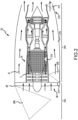
- sensing volumes for particulate sensor assemblies 200 of turbine engine 20 are illustrated in various embodiments. Sensing volumes may be defined in an inlet ingestion sensing region 202 and a turbine gas path sensing region 204.
- a first particulate sensor assembly may be coupled to engine static structure 36 proximate lip 36' to observe a first sensing volume 206 defining the inlet ingestion sensing region 202.
- a second particulate sensor assembly may be coupled to the engine static structure 36 to observe a second sensing volume 208 within bypass flow-path B proximate the inlet 214 of bypass duct 216.
- a third particulate sensor assembly may be coupled to compressor section 24 to observe a third sensing volume 210 within core flow-path C.
- a fourth particulate sensor assembly may be coupled proximate the exit 218 of bypass duct 216 to observe a fourth sensing volume 212 of the bypass flow-path B exhaust and/or the core flow-path C exhaust. It will be appreciated that any number of sensing volumes may be defined by a particulate sensor assembly configured for a particular area of interest.
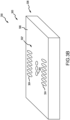
- Particulate sensor 300 comprises a multi-angle, multi-wave array (302, 302') of sensing elements 304 comprising a plurality of light sources and a plurality of sensing devices distributed on the sensor face 306 of housing 308.
- Array (302, 302') may include one or more sets of sensing elements 304 collectively configured to detect and discriminate between categories of FOD including solid objects (e.g., hand tools, hail, rain, fasteners, rocks, etc.) and particulate matter such as, for example, silicate sand, dust, volcanic ash, sea-salt aerosol, smoke, steam, water vapor, and/or the like.
- Sensing elements 304 may be distributed circumferentially about a center point (e.g., array 302) or may be distributed linearly and/or in a ladder pattern as shown by array 302'.
- particulate matter comprises particles between about 0.01 micron to about 5000 micron where about in this context means ⁇ 5%.
- the housing comprises a protective cover over the multi-angle, multi-wave array 302 tending thereby to increase the durability and longevity of the array 302 when exposed to FOD and particulate matter in the engine 20 flow-paths.
- the protective cover may be relatively translucent to the light sources and sensing devices of the array (302, 302').
- the protective cover may cover each of sensing elements 304 individually or extend over multiple sensing elements 304.
- any of the sensing elements 304 may be configured to emit a pulsed light, or a continuous light, or may be configured to receive light.
- Set 400 includes a first light sensor 402, a second light sensor 404, and a third light sensor 406 each aligned along a common axis X-X'.
- the light sensors 402, 404, 406 may include, for example, photodiodes and light sensing devices such as Avalanche PhotoDiodes (APDs), Multi-Pixel Photon Counters (MPPCs), and other photodetectors.
- Avalanche PhotoDiodes Avalanche PhotoDiodes (APDs), Multi-Pixel Photon Counters (MPPCs), and other photodetectors.
- APDs Avalanche PhotoDiodes
- MPPCs Multi-Pixel Photon Counters
- common axis X-X' may parallel engine central longitudinal axis A-A' and, in this regard, may be generally aligned with direction airflow in engine 20 flow-paths.
- the Set 400 includes a first infrared light source 408 and a first blue light source 410.
- the first infrared light source 408 and the first blue light source 410 may be divided by the common axis X-X' and located circumferentially about a center defined by the second light sensor 404.
- the first infrared light source 408 and the first blue light source 410 may define, respectively, angles ⁇ 1 and ⁇ 2 between the common axis X-X' with a vertex at a center defined by a position between any of the light sensors on the common axis.
- Angles ⁇ 1 and ⁇ 2 may be between 0° and 90°, or may be between 5° and 65°, or may be between 10° and 60°, and/or may be congruent.
- angles ⁇ 1 and ⁇ 2 may be tailored for a desired detection distance, for example, between about 1 cm to 700 cm where about in this context means ⁇ 5%.
- the vertex of angles ⁇ 1 and ⁇ 2 may lie along the common axis X-X' at the second light sensor 404, or may between the second light sensor 404 and the first light sensor 402, or may lie at the second light sensor 402.
- elements 402, 408, 406, 408, and 410 may lie at an angle with respect to the sensor face 306 (or common axis X-X' in a plane perpendicular to the sensor face 306).
- elements 402, 406, 408, and 410 may be between 5° and 60° with respect to the sensor face 306 and element 404 may be between 60° and 120° with respect to the sensor face 306.
- the first light sensor 402 is used to define a forward-scatter sensing detection volume formed by the overlap of the emission from the first infrared light source 408 and the first blue light source 410 having a first angle of coincidence.
- the first blue light source 410 emits light between 380 nm and 600 nm (e.g., a first light).
- the first infrared light source 408 emits light at a wavelength between 600 nm and 2000 nm (e.g., a second light).
- An angle of coincidence may be defined as the angle between the symmetry axis of an emitted light cone of a light source and a symmetry axis of an acceptance cone of a light sensor. Where the light source is pointed directly at the light sensor the angle of coincidence is 180°.
- a scattering angle of light may be calculated by subtracting the angle of coincidence from 180°.
- the first light sensor 402 defines a forward-scatter sensing detection volume having a first scattering angle of between 0° and 60°.
- the second light sensor 404 defines a mid-scatter sensing detection volume having a second scattering angle of between 60° and 120° and the third light sensor 406 defines a backscatter sensing detection volume having a third scattering angle between 120° and 240°.
- the first set 400 of sensing elements 304 of array 302 may include a second infrared light source 408' and a second blue light source 410'.
- the second infrared light source 408' and the second blue light source 410' are divided by the common axis X-X' and located circumferentially about the center defined by the second light sensor 404.
- the second infrared light source 408' and the second blue light source 410' may define, respectively, angles 01' and ⁇ 2' between the common axis X-X'.
- angles ⁇ 1 and ⁇ 1' may be supplementary and, in like regard, angles ⁇ 2 and ⁇ 2' may be supplementary.
- the second infrared light source 408' may emit light at a wavelength between 600 nm and 2000 nm.
- the second blue light source 410' may emit light between 380 nm and 700 nm.
- the first set 400 of sensing elements 304 of array 302 may include a third infrared light source 409 and a third blue light source 411.
- the third infrared light source 409 and the third blue light source 411 may be positioned along the common axis X-X' relatively between the first light sensor 402 and the third light sensor 406.
- the third infrared light source 409 may emit light at a wavelength between 700 nm and 2000 nm.
- the third blue light source 411 may emit light between 250 nm and 700 nm.
- Each of the third infrared light source 409 and the third blue light source 411 may have a symmetry axis of the respective emitted light cone perpendicular to, or between 60° and 120° of, a plane defined by the sensor face 306 and or the light sensors 402, 404, 406.
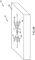
- a second set 500 of sensing elements 304 of array 302 comprising at least one of a polarized light emitting element or a polarized light detecting element.
- set 500 may be configured for any combination of elliptical and linear polarization and may include various chirality.
- Second set 500 may include a first element 502, a second element 504, and a third element 506.
- Each of the elements (502, 504, 506) may be distributed circumferentially about a vertex 508 defined by an element light cone axis of each of the receiving and/or emitting light cones of each of the elements (502, 504, 506).
- the vertex may be projected in the plane of sensor face 306 to the center defined by the second light sensor 404.
- the first element 502 is an unpolarized light emitting element
- the second element 504 is a S polarization detecting element
- the third element 506 is a P polarization detecting element.
- the first element 502 is an unpolarized polarization detector
- the second element 504 is a P polarized light emitting element
- the third element 506 is a S polarized light emitting element (or vice versa).
- the second element 504 and the third element 506 may define an angle ⁇ therebetween as a projection of the element light cone axis in the plane of sensor face 306.
- the angle ⁇ may be 120°.
- the second set 500 may include a V polarized light emitting element with an element light cone axis oriented at 90° to an element light cone axis of the P polarized light emitting element (e.g., respectively orthogonal beamlines).
- any of the vertex 508 angles between the light cone axes of the elements may be ⁇ 30° from orthogonal (i.e., between 60° and 120°).
- the elements 502, 504, 506 may be configured to operate at wavelengths between 400 nm and 1100 nm (e.g., a fifth light).
- the elements 502, 504, 406 may emit a laser light characterized by coherence.
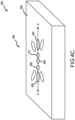
- the third set 600 includes paired ultraviolet light emitting elements 602 and fluorescent light detecting elements 604 divided by the common axis X-X' and located circumferentially about the center defined by the second light sensor 404.
- the emitting element and the detecting element of the respective pair may be located relatively circumferentially 180° apart.
- the emitting elements 602 may be configured to emit ultraviolet light between 220 nm and 405 nm (e.g., a third light).
- the fluorescent light detecting elements may comprise one or more filters tending thereby to enable greater discrimination within the fluorescence spectra.
- detecting elements 604 may include a first filter 606 configured between 330 nm and 370 nm, a second filter 608 configured between 370 nm and 410 nm, a third filter 610 configured between 410 nm and 450 nm, and a fourth filter 612 configured between 460 nm and 500 nm.
- the elements 602 may include an X-ray emitting source (e.g., a fourth light) and the elements 604 may include an X-ray fluorescence detector.
- a scattering angle for a fluorescence detector may be between 5° and 180°.
- System 700 for particulate discrimination is illustrated aboard an aircraft 10.
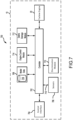
- System 700 comprises a controller 702 a control interface 704, sensors 706, a database 708, a discrimination module 710, a debris damage module 712, and an engine control module 714.
- controller 702 may be integrated into computer systems onboard aircraft 10. In various embodiments, controller 702 may be configured as a central network element or hub to access various systems, engines, and components of system 700. Controller 702 may comprise a network, computer-based system, and/or software components configured to provide an access point to various systems, engines, and components of system 700. In various embodiments, controller 702 may comprise a processor. In various embodiments, controller 702 may be implemented in a single processor. In various embodiments, controller 702 may be implemented as and may include one or more processors and/or one or more tangible, non-transitory memories and be capable of implementing logic.
- Each processor can be a general purpose processor, a digital signal processor (DSP), an application specific integrated circuit (ASIC), a field programmable gate array (FPGA) or other programmable logic device, discrete gate or transistor logic, discrete hardware components, or any combination thereof.
- Controller 702 may comprise a processor configured to implement various logical operations in response to execution of instructions, for example, instructions stored on a non-transitory, tangible, computer-readable medium configured to communicate with controller 702.
- System program instructions and/or controller instructions may be loaded onto a non-transitory, tangible computer-readable medium having instructions stored thereon that, in response to execution by a controller, cause the controller to perform various operations.
- non-transitory is to be understood to remove only propagating transitory signals per se from the claim scope and does not relinquish rights to all standard computer-readable media that are not only propagating transitory signals per se.
- controller 702 may be in electronic communication with a pilot through a control interface 704, for example, a multifunction display a pilot can operate.
- the control interface 704 may enable a pilot to interact with system 700 for example, to issue commands, display information such as, for example, warnings, or receive outputs.
- Control interface 704 may comprise any suitable combination of hardware, software, and/or database components.
- controller 702 may be in electronic communication with sensors 706 including at least one particulate sensor 300.
- Sensors 706 may comprise a temperature sensor, a torque sensor, a speed sensor, a pressure sensor, a position sensor, an accelerometer, a mass flow sensor, or any other suitable measuring device known to those skilled in the art.
- Sensors 706 may be configured to measure a characteristic of an aircraft 10 system or component such as gas turbine engine 20.
- Sensors 706 may include sensors configured to measure atmospheric data or Global Positioning System (GPS) data.
- GPS Global Positioning System
- Sensors 706 may be configured to transmit measurements to controller 702, thereby providing sensor feedback about the aircraft 10 systems to controller 702.
- the sensor feedback may be, for example, a speed signal, or may be position feedback, temperature feedback, pressure feedback and/or other data.
- sensors 706 include each of the particulate sensor assemblies 200 of turbine engine 20 having the sensing volumes as illustrated with reference to FIG. 2 .
- Controller 702 may be in electronic communication with database 708.
- Database 708 may be configured to communicate with controller 702 and to store and maintain data such as sensor data, configuration settings, response models such as, for example, model data 716, and/or the like. Data may be stored or recalled from database 708 in response to commands from controller 702. Data may be stored in database 708 using any suitable technique described herein or known in the art.
- Controller 702 may be in electronic communication with discrimination module 710.
- Discrimination module 710 may receive sensor data 718 from sensors 706 including from particulate sensors 300.
- Discrimination module 710 is configured to detect and discriminate between categories of foreign object debris including solid objects (e.g., hand tools, hail, rain, fasteners, rocks, etc.) and particulate matter including, for example, silicate sand, dust, volcanic ash, sea-salt aerosol, smoke, steam, water vapor, and/or the like.
- Discrimination module 710 may discriminate between categories of foreign object debris including solid objects and particulates including silicate sand, water vapor, dust, volcanic ash, sea-salt aerosol, and smoke based on the sensor data 718 and algorithms including the model data 716 which may define the various categories of FOD and particulate matter. Discrimination module 710 may determine a quantity, a size, and a type of the particulate matter.
- the sensor data 718 may include GPS data and/or atmospheric data.
- Controller 702 may be in electronic communication with debris damage module 712.
- Debris damage module 712 may receive outputs from the discrimination module 710 and/or the sensor data 718.
- the debris damage module 712 may be configured to determine a particulate concentration across plurality of particulate sensors within a turbine engine. In this regard, debris damage module 712 may determine a quantity or time-based map of ingested particles between an inlet and an exhaust of a bypass flow-path or a core flow-path.
- the debris damage module 712 may determine a hazard level for a given particulate type and/or concentration.
- the debris damage module 712 may record debris data based on the hazard level, the particulate type, or the particulate concentration.
- the damage module 712 may generate a debris alert or a damage alert via the control interface 704.
- the damage module 712 may calculate and/or asses an accumulated engine damage using a physics-based model (i.e., a damage model) of turbine engine 20.
- the damage model may be stored in database 708 as model data 716.
- the damage model may include modeling of gas turbine engine 20 component erosion based on particulate type.
- the debris damage module 712 may determine based on the accumulated damage a percentage of engine life remaining or a time before engine failure and display these measures via the control interface 704.
- the damage module 712 may generate an alert based on accumulated damage a percentage of engine life remaining such as, for example, exceeding a threshold value for either measure.
- Controller 702 may be in electronic communication with engine control module 714.
- Engine control module 714 may be configured to command turbine engine 20.
- engine control module 20 may enable controller 702 to instruct turbine engine 20 to increase or decrease shaft speeds, fuel flow, vane geometry, alter bypass airflow, set valves, etc.
- the controller 702 may control the turbine engine 20 based on debris damage module 712 and/or discrimination module 710 outputs.
- engine control module may pull fuel flow from turbine engine 20 in response to exceeding an engine damage threshold.
- references to "various embodiments,” “one embodiment,” “an embodiment,” “an example embodiment,” etc. indicate that the embodiment described may include a particular feature, structure, or characteristic, but every embodiment may not necessarily include the particular feature, structure, or characteristic. Moreover, such phrases are not necessarily referring to the same embodiment. Further, when a particular feature, structure, or characteristic is described in connection with an embodiment, it is submitted that it is within the knowledge of one skilled in the art to affect such feature, structure, or characteristic in connection with other embodiments whether or not explicitly described. After reading the description, it will be apparent to one skilled in the relevant art(s) how to implement the disclosure in alternative embodiments.
Landscapes
- Chemical & Material Sciences (AREA)
- Health & Medical Sciences (AREA)
- Immunology (AREA)
- Life Sciences & Earth Sciences (AREA)
- Physics & Mathematics (AREA)
- Analytical Chemistry (AREA)
- General Health & Medical Sciences (AREA)
- General Physics & Mathematics (AREA)
- Biochemistry (AREA)
- Pathology (AREA)
- Dispersion Chemistry (AREA)
- Molecular Biology (AREA)
- Chemical Kinetics & Catalysis (AREA)
- Optics & Photonics (AREA)
- Nuclear Medicine, Radiotherapy & Molecular Imaging (AREA)
- Investigating Or Analysing Materials By Optical Means (AREA)
Claims (11)
- Procédé de fonctionnement d'un ensemble capteur de particules (200) disposé dans un trajet d'écoulement de moteur à turbine à gaz (A, B, C), comprenant :l'émission d'une première lumière à une longueur d'onde comprise entre 380 nanomètres et 600 nanomètres à partir d'une première source lumineuse (410) ;l'émission d'une deuxième lumière à une longueur d'onde comprise entre 600 nanomètres et 2 000 nanomètres à partir d'une deuxième source lumineuse (408) ;la détection d'une lumière diffusée à partir de chacune de la première lumière et de la deuxième lumière au niveau d'une pluralité de premiers dispositifs de détection de lumière (402, 404, 406), la pluralité de premiers dispositifs de détection de lumière comportant un premier capteur de lumière (402) définissant un volume de détection de détection de diffusion vers l'avant ayant un premier angle de diffusion compris entre 0° et 60°, un deuxième capteur de lumière (404) définissant un volume de détection de détection de diffusion médiane ayant un deuxième angle de diffusion compris entre 60° et 120°, et un troisième capteur de lumière (406) définissant un volume de détection de détection de rétrodiffusion ayant un troisième angle de diffusion entre 120° et 240°, dans lequel le premier capteur de lumière, le deuxième capteur de lumière et le troisième capteur de lumière sont alignés sur un axe commun (X-X'), et dans lequel la première source lumineuse (410) et la deuxième source lumineuse (408) sont divisées par l'axe commun (X-X') ;l'émission d'une troisième lumière à une longueur d'onde comprise entre 220 nanomètres et 405 nanomètres à partir d'une pluralité de troisièmes sources lumineuses (602) ; etla détection de lumière diffusée à partir de la troisième lumière au niveau d'une pluralité de dispositifs de détection de lumière fluorescente (604), dans lequel chacune des troisièmes sources lumineuses est couplée à un dispositif de détection de lumière fluorescente (604), chaque troisième source lumineuse couplée (602) et chaque dispositif de détection de lumière fluorescente (604) étant divisés par l'axe commun (X-X'),dans lequel la détection de lumière diffusée est déterminante entre des catégories de débris de corps étrangers comprenant des objets solides et des particules comprenant du sable de silice, de la vapeur d'eau, de la poussière, des cendres volcaniques, des aérosols de sel marin et de la fumée,dans lequel l'ensemble capteur de particules (200) comporte un réseau à angles multiples et à ondes multiples (302) d'éléments de détection (304), le réseau à angles multiples et à ondes multiples (302) d'éléments de détection (304) comprenant un premier jeu (400) d'éléments de détection (304) et un deuxième jeu (500) d'éléments de détection (304), le premier jeu (400) d'éléments de détection (304) comportant la première source lumineuse (410), la deuxième source lumineuse (408), et la pluralité de premiers dispositifs de détection de lumière (402, 404, 406) ; le deuxième jeu (500) d'éléments de détection (304) comportant la pluralité de troisièmes sources lumineuses (602) et la pluralité de dispositifs de détection de lumière fluorescente (604), dans lequel l'axe commun (X-X') est généralement aligné avec la direction du flux d'air dans le trajet d'écoulement (A, B, C).
- Procédé selon la revendication 1, comprenant en outre l'émission d'une quatrième lumière à une longueur d'onde comprise entre 0,01 nanomètre et 10 nanomètres à une longueur d'onde de rayons X à partir d'une quatrième source lumineuse (602) et la détection de lumière diffusée à partir de la quatrième lumière au niveau de la pluralité de dispositifs de détection de lumière fluorescente (604), dans lequel le deuxième jeu (500) d'éléments de détection (304) comporte la quatrième source lumineuse (602).
- Procédé selon la revendication 1 ou 2, comprenant en outre l'émission d'une cinquième lumière à une longueur d'onde comprise entre 400 nm et 1 100 nanomètres à partir d'une cinquième source lumineuse (502) et la détection de la lumière diffusée à partir de la cinquième lumière au niveau d'un troisième dispositif de détection de lumière (504, 506), dans lequel le réseau à longueurs d'onde multiples (302) de dispositifs de détection (304) comprend en outre un troisième jeu (600) d'éléments de détection (304), le troisième jeu d'éléments de détection comportant la cinquième source lumineuse (502) et le troisième dispositif de détection de lumière (504, 506) .
- Procédé selon la revendication 3, dans lequel la cinquième lumière comprend une lumière polarisée P et une lumière polarisée S définissant chacune respectivement des lignes de faisceau orthogonales.
- Procédé selon la revendication 3 ou 4, comprenant en outre la détection d'une lumière polarisée P et d'une lumière polarisée S à partir de la lumière diffusée de la cinquième lumière au niveau du troisième dispositif de détection de lumière (504, 506).
- Procédé selon la revendication 3, 4 ou 5, dans lequel la cinquième lumière est une lumière laser.
- Procédé selon une quelconque revendication précédente, dans lequel la détection de la lumière diffusée comporte la détection d'une lumière fluorescente émise en réponse à l'émission d'au moins l'une parmi la première lumière, la deuxième lumière ou la troisième lumière.
- Procédé selon l'une quelconque des revendications 2 à 7, dans lequel la détection de la lumière diffusée comporte la détection d'une lumière fluorescente émise en réponse à l'émission de la quatrième lumière.
- Système de discrimination de particules, comprenant :un moteur à turbine à gaz (20) ;un ensemble capteur de particules (200) couplé au moteur à turbine à gaz, l'ensemble capteur de particules comportant un réseau à angles multiples et à ondes multiples (302), le réseau à angles multiples et à ondes multiples (302) comprenant un premier jeu d'éléments de capteurs (304) comportant une première source lumineuse (410), une deuxième source lumineuse (408) et une pluralité de premiers dispositifs de détection de lumière (402, 404, 406), etun deuxième jeu (500) d'éléments de détection (304) comportant une pluralité de troisièmes sources lumineuses (602) configurées pour émettre de la lumière entre 220 nm et 405 nm et une pluralité de dispositifs de détection de lumière fluorescente (604),dans lequel la pluralité de premiers dispositifs de détection de lumière (402, 404, 406) comprend un premier capteur de lumière (402) définissant un volume de détection de détection de diffusion vers l'avant ayant un premier angle de diffusion compris entre 0° et 60°, un deuxième capteur de lumière (404) définissant un volume de détection de détection de diffusion médiane ayant un deuxième angle de diffusion compris entre 60° et 120°, et un troisième capteur de lumière (406) définissant un volume de détection de détection de rétrodiffusion ayant un troisième angle de diffusion compris entre 120° et 240°,dans lequel le premier capteur de lumière (402), le deuxième capteur de lumière (404) et le troisième capteur de lumière (406) sont alignés sur un axe commun (X-X'), et dans lequel la première source lumineuse (410) et la deuxième source lumineuse (408) sont divisées par l'axe commun (X-X'), etdans lequel chacune des troisièmes sources lumineuses est couplée avec un dispositif de détection de lumière fluorescente (604), et chaque troisième source lumineuse couplée (602) et chaque dispositif de détection de lumière fluorescente (604) sont divisés par l'axe commun (X-X') ;dans lequel l'axe commun (X-X') est généralement aligné avec la direction du flux d'air dans un trajet d'écoulement (A, B, C) du moteur à turbine à gaz (20) ; etune mémoire tangible non transitoire configurée pour communiquer avec un dispositif de commande (702), la mémoire tangible non transitoire dans laquelle sont stockées des instructions qui, en réponse à l'exécution par le dispositif de commande, amènent le dispositif de commande à effectuer des opérations comprenant :l'émission, par le dispositif de commande via la première source lumineuse (410), d'une première lumière à une longueur d'onde comprise entre 380 nanomètres et 600 nanomètres ;l'émission, par le dispositif de commande via la deuxième source lumineuse (408), d'une deuxième lumière à une longueur d'onde comprise entre 600 nanomètres et 2 000 nanomètres ;l'émission, par le dispositif de commande via la troisième source lumineuse (602), d'une troisième lumière à une longueur d'onde comprise entre 220 nanomètres et 405 nanomètres ;la réception, par le dispositif de commande via les premier, deuxième et troisième capteurs de lumière (402, 404, 406) et le dispositif de détection de lumière fluorescente (604), d'une lumière diffusée de chacune de la première source lumineuse, de la deuxième source lumineuse et des troisièmes sources lumineuses ;la discrimination, par le dispositif de commande, sur la base de la lumière diffusée, entre un débris de corps étranger et une matière particulaire ; etla détermination, par le dispositif de commande, sur la base de la lumière diffusée, d'une quantité, d'une taille et d'un type de matière particulaire.
- Système selon la revendication 9, dans lequel le type de matière particulaire comprend au moins l'un parmi du sable de silice, de la vapeur d'eau, de la poussière, des cendres volcaniques, de la vapeur, un aérosol de sel marin et de la fumée.
- Système selon la revendication 9 ou 10, comprenant en outre une source d'émission de rayons X (602) et un dispositif de détection de fluorescence de rayons X (604), dans lequel les opérations comprennent en outre :l'émission, par le dispositif de commande (702) via la source d'émission de rayons X, d'une quatrième lumière à une longueur d'onde de rayons X,la réception, par le dispositif de commande via le dispositif de détection de fluorescence de rayons X, d'une lumière fluorescente de rayons X émise en réponse à la quatrième lumière ; etla détermination, par le dispositif de commande, de la quantité, de la taille et du type sur la base d'au moins l'une de la lumière diffusée provenant de la lumière fluorescente à rayons X, et/oudans lequel les opérations comprennent en outre :la réception, par le dispositif de commande, d'une lumière fluorescente émise en réponse à l'émission d'au moins l'une parmi la première lumière, la deuxième lumière ou la troisième lumière ; et la détermination, par le dispositif de commande, de la quantité, de la taille et du type en fonction de la lumière fluorescente, et/oudans lequel le système comprend en outre un troisième jeu (500) d'éléments de détection (304) comprenant au moins l'un parmi un élément émetteur de lumière polarisée ou un élément de détection de lumière polarisée, et les opérations comprennent en outre :l'émission, par le dispositif de commande via un élément émetteur de lumière du troisième jeu (500) d'éléments de détection (304), d'une cinquième lumière à une longueur d'onde comprise entre 400 nanomètres et 1 100 nanomètres ; etla détermination, par le dispositif de commande via un élément récepteur de lumière du troisième jeu (500) d'éléments de détection (304), de la quantité, de la taille et du type sur la base d'une polarisation P et d'une polarisation S de la lumière diffusée à partir de la cinquième lumière.
Applications Claiming Priority (1)
| Application Number | Priority Date | Filing Date | Title |
|---|---|---|---|
| US16/503,057 US10845294B1 (en) | 2019-07-03 | 2019-07-03 | Systems and methods for particulate ingestion sensing in gas turbine engines |
Publications (2)
| Publication Number | Publication Date |
|---|---|
| EP3761009A1 EP3761009A1 (fr) | 2021-01-06 |
| EP3761009B1 true EP3761009B1 (fr) | 2023-05-03 |
Family
ID=71409153
Family Applications (1)
| Application Number | Title | Priority Date | Filing Date |
|---|---|---|---|
| EP20183102.1A Active EP3761009B1 (fr) | 2019-07-03 | 2020-06-30 | Systèmes et procédés de détection d'ingestion de particules dans des moteurs à turbine à gaz |
Country Status (2)
| Country | Link |
|---|---|
| US (1) | US10845294B1 (fr) |
| EP (1) | EP3761009B1 (fr) |
Families Citing this family (7)
| Publication number | Priority date | Publication date | Assignee | Title |
|---|---|---|---|---|
| US11492967B2 (en) * | 2019-07-03 | 2022-11-08 | Raytheon Technologies Corporation | Particulate ingestion sensor for gas turbine engines |
| US12196658B2 (en) * | 2020-12-01 | 2025-01-14 | Rtx Corporation | Optical particulate detection for an aircraft |
| US11726035B2 (en) * | 2020-12-11 | 2023-08-15 | Raytheon Technologies Corporation | Terahertz enhanced foreign object debris discrimination for optical particulate sensor |
| US12019028B2 (en) | 2021-07-23 | 2024-06-25 | Rtx Corporation | Foreign object debris discrimination with modulated laser light |
| US12331681B2 (en) * | 2023-05-09 | 2025-06-17 | Rtx Corporation | Aircraft precipitation monitoring system |
| US11906017B1 (en) * | 2023-06-02 | 2024-02-20 | Pratt & Whitney Canada Corp. | Drive assembly and method of assembly |
| US12391393B2 (en) | 2023-07-20 | 2025-08-19 | Rtx Corporation | Aircraft propulsion system with inlet air monitoring system and method |
Family Cites Families (24)
| Publication number | Priority date | Publication date | Assignee | Title |
|---|---|---|---|---|
| GB8707187D0 (en) * | 1987-03-25 | 1987-04-29 | Hughes Ltd Stewart | Monitoring of foreign object in engines |
| US5164604A (en) | 1991-05-01 | 1992-11-17 | Allied-Signal Inc. | Multiport particle detection apparatus utilizing a plenum having a plurality of spatically separate channels in fluid combination |
| JP5115912B2 (ja) | 2001-02-23 | 2013-01-09 | 独立行政法人日本原子力研究開発機構 | 高速ゲート掃引型3次元レーザーレーダー装置 |
| JP4598766B2 (ja) | 2003-04-29 | 2010-12-15 | エス3アイ, エル エル シィ | 生物学的微粒子及び非生物学的微粒子を検出し且つ分類するためのマルチスペクトル光学方法及びシステム |
| GB0500687D0 (en) * | 2005-01-14 | 2005-02-23 | Unidata Europ Ltd | Particulate detector |
| US7742167B2 (en) * | 2005-06-17 | 2010-06-22 | Perkinelmer Health Sciences, Inc. | Optical emission device with boost device |
| US7518710B2 (en) * | 2005-07-14 | 2009-04-14 | Battelle Memorial Institute | Optical devices for biological and chemical detection |
| US8424279B2 (en) * | 2007-03-28 | 2013-04-23 | United Technologies Corporation | Particle separator and debris control system |
| US20090112519A1 (en) * | 2007-10-31 | 2009-04-30 | United Technologies Corporation | Foreign object/domestic object damage assessment |
| KR20130054285A (ko) | 2010-04-29 | 2013-05-24 | 노르스크 인스티튜트 포 러프트포르스크닝 | 항공기 앞의 불리한 대기 조건들을 감지하는 시스템 및 방법 |
| US9018583B2 (en) * | 2011-03-08 | 2015-04-28 | Magee Scientific Corporation | Method for automatic performance diagnosis and calibration of a photometric particle analyzer |
| US9010198B2 (en) * | 2011-07-29 | 2015-04-21 | United Technologies Corporation | Aircraft debris monitoring sensor assembly |
| US9222873B2 (en) * | 2013-05-02 | 2015-12-29 | Droplet Measurement Technologies, Inc. | Optical particle detector |
| EP3041743B1 (fr) | 2013-09-06 | 2020-01-01 | GE Aviation Systems LLC | Avion, et procédé de détection de particules |
| US9915600B2 (en) * | 2016-02-19 | 2018-03-13 | Research Triangle Institute | Devices, systems and methods for detecting particles |
| DE102015117361A1 (de) * | 2014-10-13 | 2016-04-14 | Universität Duisburg-Essen | Vorrichtung zur Identifikation von Aerosolen |
| US10458990B1 (en) * | 2015-03-06 | 2019-10-29 | Scanit Technologies, Inc. | Spore state discrimination |
| CH711170A1 (de) * | 2015-06-08 | 2016-12-15 | Fachhochschule Nordwestschweiz Fhnw | Verfahren und Vorrichtung zur Detektion von Aerosolpartikeln. |
| US10871452B2 (en) * | 2016-06-15 | 2020-12-22 | Kidde Technologies, Inc. | Systems and methods for chamberless smoke detection and indoor air quality monitoring |
| US10852233B2 (en) * | 2016-06-15 | 2020-12-01 | Kidde Technologies, Inc. | Systems and methods for chamberless smoke detection and indoor air quality monitoring |
| US20180068498A1 (en) * | 2016-09-06 | 2018-03-08 | Rolls-Royce North American Technologies, Inc. | Systems and methods of modifying turbine engine operating limits |
| US20180136122A1 (en) | 2016-11-11 | 2018-05-17 | Kidde Technologies, Inc. | High sensitivity fiber optic based detection |
| US20180298778A1 (en) | 2017-04-18 | 2018-10-18 | Honeywell International Inc. | Gas turbine engine particulate ingestion and accumulation sensor system and method |
| US10620342B2 (en) | 2017-09-28 | 2020-04-14 | Rosemount Aerospace Inc. | Microscopic imager for aircraft cloud condition detection |
-
2019
- 2019-07-03 US US16/503,057 patent/US10845294B1/en active Active
-
2020
- 2020-06-30 EP EP20183102.1A patent/EP3761009B1/fr active Active
Also Published As
| Publication number | Publication date |
|---|---|
| US10845294B1 (en) | 2020-11-24 |
| EP3761009A1 (fr) | 2021-01-06 |
Similar Documents
| Publication | Publication Date | Title |
|---|---|---|
| EP3761009B1 (fr) | Systèmes et procédés de détection d'ingestion de particules dans des moteurs à turbine à gaz | |
| US11346239B2 (en) | Heat flux measurement system | |
| EP3760839B1 (fr) | Ensemble capteur de détection de particules pour moteurs à turbine à gaz | |
| US10196928B2 (en) | Method and system for piping failure detection in a gas turbine bleeding air system | |
| EP3361229B1 (fr) | Système et procédé de surveillance de la santé de la pale de rotor | |
| CN108204872B (zh) | 用于燃气涡轮发动机的扭矩监测装置 | |
| US8869603B2 (en) | Debris detection in turbomachinery and gas turbine engines | |
| US20180330557A1 (en) | Fault detection using high resolution realms | |
| JP6505179B2 (ja) | 排気ガス温度検出プローブアセンブリ | |
| EP3663516B1 (fr) | Inspection de composants utilisant des poids actuels mesurés et théoriques | |
| US20240052757A1 (en) | Detection of gas turbine engine blade abnormalities based on light reflections | |
| EP4538518A1 (fr) | Système de contrôle des émissions en vol et des contre-coups | |
| Van Zante et al. | Testing and performance verification of a high bypass ratio turbofan rotor in an internal flow component test facility | |
| Key et al. | Vane clocking in a three-stage compressor: Frequency domain data analysis | |
| US11946811B2 (en) | Non-contact high temperature measurement system | |
| US12196658B2 (en) | Optical particulate detection for an aircraft | |
| US12123313B2 (en) | In-flight measured propulsion mass flow and thrust on aircraft | |
| US11243158B2 (en) | Determining presence of internal corrosion within a rotor blade by measuring magnetic characteristic(s) | |
| US12540882B2 (en) | Accretion detection systems and associated methods for gas turbine engines |
Legal Events
| Date | Code | Title | Description |
|---|---|---|---|
| PUAI | Public reference made under article 153(3) epc to a published international application that has entered the european phase |
Free format text: ORIGINAL CODE: 0009012 |
|
| STAA | Information on the status of an ep patent application or granted ep patent |
Free format text: STATUS: THE APPLICATION HAS BEEN PUBLISHED |
|
| AK | Designated contracting states |
Kind code of ref document: A1 Designated state(s): AL AT BE BG CH CY CZ DE DK EE ES FI FR GB GR HR HU IE IS IT LI LT LU LV MC MK MT NL NO PL PT RO RS SE SI SK SM TR |
|
| AX | Request for extension of the european patent |
Extension state: BA ME |
|
| STAA | Information on the status of an ep patent application or granted ep patent |
Free format text: STATUS: REQUEST FOR EXAMINATION WAS MADE |
|
| 17P | Request for examination filed |
Effective date: 20210706 |
|
| RBV | Designated contracting states (corrected) |
Designated state(s): AL AT BE BG CH CY CZ DE DK EE ES FI FR GB GR HR HU IE IS IT LI LT LU LV MC MK MT NL NO PL PT RO RS SE SI SK SM TR |
|
| GRAP | Despatch of communication of intention to grant a patent |
Free format text: ORIGINAL CODE: EPIDOSNIGR1 |
|
| STAA | Information on the status of an ep patent application or granted ep patent |
Free format text: STATUS: GRANT OF PATENT IS INTENDED |
|
| RIC1 | Information provided on ipc code assigned before grant |
Ipc: G01N 15/00 20060101ALN20221124BHEP Ipc: G01N 15/02 20060101ALN20221124BHEP Ipc: G01N 21/47 20060101ALN20221124BHEP Ipc: G01N 21/53 20060101ALI20221124BHEP Ipc: G01N 15/14 20060101ALI20221124BHEP Ipc: G01N 15/10 20060101ALI20221124BHEP Ipc: G01N 15/06 20060101ALI20221124BHEP Ipc: F02C 7/04 20060101ALI20221124BHEP Ipc: G01N 21/64 20060101AFI20221124BHEP |
|
| INTG | Intention to grant announced |
Effective date: 20221208 |
|
| GRAS | Grant fee paid |
Free format text: ORIGINAL CODE: EPIDOSNIGR3 |
|
| GRAA | (expected) grant |
Free format text: ORIGINAL CODE: 0009210 |
|
| STAA | Information on the status of an ep patent application or granted ep patent |
Free format text: STATUS: THE PATENT HAS BEEN GRANTED |
|
| AK | Designated contracting states |
Kind code of ref document: B1 Designated state(s): AL AT BE BG CH CY CZ DE DK EE ES FI FR GB GR HR HU IE IS IT LI LT LU LV MC MK MT NL NO PL PT RO RS SE SI SK SM TR |
|
| REG | Reference to a national code |
Ref country code: GB Ref legal event code: FG4D |
|
| REG | Reference to a national code |
Ref country code: AT Ref legal event code: REF Ref document number: 1565015 Country of ref document: AT Kind code of ref document: T Effective date: 20230515 Ref country code: CH Ref legal event code: EP |
|
| REG | Reference to a national code |
Ref country code: DE Ref legal event code: R096 Ref document number: 602020010293 Country of ref document: DE |
|
| REG | Reference to a national code |
Ref country code: IE Ref legal event code: FG4D |
|
| P01 | Opt-out of the competence of the unified patent court (upc) registered |
Effective date: 20230603 |
|
| REG | Reference to a national code |
Ref country code: LT Ref legal event code: MG9D |
|
| REG | Reference to a national code |
Ref country code: NL Ref legal event code: MP Effective date: 20230503 |
|
| REG | Reference to a national code |
Ref country code: AT Ref legal event code: MK05 Ref document number: 1565015 Country of ref document: AT Kind code of ref document: T Effective date: 20230503 |
|
| PG25 | Lapsed in a contracting state [announced via postgrant information from national office to epo] |
Ref country code: SE Free format text: LAPSE BECAUSE OF FAILURE TO SUBMIT A TRANSLATION OF THE DESCRIPTION OR TO PAY THE FEE WITHIN THE PRESCRIBED TIME-LIMIT Effective date: 20230503 Ref country code: PT Free format text: LAPSE BECAUSE OF FAILURE TO SUBMIT A TRANSLATION OF THE DESCRIPTION OR TO PAY THE FEE WITHIN THE PRESCRIBED TIME-LIMIT Effective date: 20230904 Ref country code: NO Free format text: LAPSE BECAUSE OF FAILURE TO SUBMIT A TRANSLATION OF THE DESCRIPTION OR TO PAY THE FEE WITHIN THE PRESCRIBED TIME-LIMIT Effective date: 20230803 Ref country code: NL Free format text: LAPSE BECAUSE OF FAILURE TO SUBMIT A TRANSLATION OF THE DESCRIPTION OR TO PAY THE FEE WITHIN THE PRESCRIBED TIME-LIMIT Effective date: 20230503 Ref country code: ES Free format text: LAPSE BECAUSE OF FAILURE TO SUBMIT A TRANSLATION OF THE DESCRIPTION OR TO PAY THE FEE WITHIN THE PRESCRIBED TIME-LIMIT Effective date: 20230503 Ref country code: AT Free format text: LAPSE BECAUSE OF FAILURE TO SUBMIT A TRANSLATION OF THE DESCRIPTION OR TO PAY THE FEE WITHIN THE PRESCRIBED TIME-LIMIT Effective date: 20230503 |
|
| RAP4 | Party data changed (patent owner data changed or rights of a patent transferred) |
Owner name: RTX CORPORATION |
|
| PG25 | Lapsed in a contracting state [announced via postgrant information from national office to epo] |
Ref country code: RS Free format text: LAPSE BECAUSE OF FAILURE TO SUBMIT A TRANSLATION OF THE DESCRIPTION OR TO PAY THE FEE WITHIN THE PRESCRIBED TIME-LIMIT Effective date: 20230503 Ref country code: PL Free format text: LAPSE BECAUSE OF FAILURE TO SUBMIT A TRANSLATION OF THE DESCRIPTION OR TO PAY THE FEE WITHIN THE PRESCRIBED TIME-LIMIT Effective date: 20230503 Ref country code: LV Free format text: LAPSE BECAUSE OF FAILURE TO SUBMIT A TRANSLATION OF THE DESCRIPTION OR TO PAY THE FEE WITHIN THE PRESCRIBED TIME-LIMIT Effective date: 20230503 Ref country code: LT Free format text: LAPSE BECAUSE OF FAILURE TO SUBMIT A TRANSLATION OF THE DESCRIPTION OR TO PAY THE FEE WITHIN THE PRESCRIBED TIME-LIMIT Effective date: 20230503 Ref country code: IS Free format text: LAPSE BECAUSE OF FAILURE TO SUBMIT A TRANSLATION OF THE DESCRIPTION OR TO PAY THE FEE WITHIN THE PRESCRIBED TIME-LIMIT Effective date: 20230903 Ref country code: HR Free format text: LAPSE BECAUSE OF FAILURE TO SUBMIT A TRANSLATION OF THE DESCRIPTION OR TO PAY THE FEE WITHIN THE PRESCRIBED TIME-LIMIT Effective date: 20230503 Ref country code: GR Free format text: LAPSE BECAUSE OF FAILURE TO SUBMIT A TRANSLATION OF THE DESCRIPTION OR TO PAY THE FEE WITHIN THE PRESCRIBED TIME-LIMIT Effective date: 20230804 |
|
| PG25 | Lapsed in a contracting state [announced via postgrant information from national office to epo] |
Ref country code: FI Free format text: LAPSE BECAUSE OF FAILURE TO SUBMIT A TRANSLATION OF THE DESCRIPTION OR TO PAY THE FEE WITHIN THE PRESCRIBED TIME-LIMIT Effective date: 20230503 |
|
| PG25 | Lapsed in a contracting state [announced via postgrant information from national office to epo] |
Ref country code: SK Free format text: LAPSE BECAUSE OF FAILURE TO SUBMIT A TRANSLATION OF THE DESCRIPTION OR TO PAY THE FEE WITHIN THE PRESCRIBED TIME-LIMIT Effective date: 20230503 |
|
| PG25 | Lapsed in a contracting state [announced via postgrant information from national office to epo] |
Ref country code: SM Free format text: LAPSE BECAUSE OF FAILURE TO SUBMIT A TRANSLATION OF THE DESCRIPTION OR TO PAY THE FEE WITHIN THE PRESCRIBED TIME-LIMIT Effective date: 20230503 Ref country code: SK Free format text: LAPSE BECAUSE OF FAILURE TO SUBMIT A TRANSLATION OF THE DESCRIPTION OR TO PAY THE FEE WITHIN THE PRESCRIBED TIME-LIMIT Effective date: 20230503 Ref country code: RO Free format text: LAPSE BECAUSE OF FAILURE TO SUBMIT A TRANSLATION OF THE DESCRIPTION OR TO PAY THE FEE WITHIN THE PRESCRIBED TIME-LIMIT Effective date: 20230503 Ref country code: EE Free format text: LAPSE BECAUSE OF FAILURE TO SUBMIT A TRANSLATION OF THE DESCRIPTION OR TO PAY THE FEE WITHIN THE PRESCRIBED TIME-LIMIT Effective date: 20230503 Ref country code: DK Free format text: LAPSE BECAUSE OF FAILURE TO SUBMIT A TRANSLATION OF THE DESCRIPTION OR TO PAY THE FEE WITHIN THE PRESCRIBED TIME-LIMIT Effective date: 20230503 Ref country code: CZ Free format text: LAPSE BECAUSE OF FAILURE TO SUBMIT A TRANSLATION OF THE DESCRIPTION OR TO PAY THE FEE WITHIN THE PRESCRIBED TIME-LIMIT Effective date: 20230503 |
|
| REG | Reference to a national code |
Ref country code: CH Ref legal event code: PL |
|
| REG | Reference to a national code |
Ref country code: DE Ref legal event code: R097 Ref document number: 602020010293 Country of ref document: DE |
|
| REG | Reference to a national code |
Ref country code: BE Ref legal event code: MM Effective date: 20230630 |
|
| PG25 | Lapsed in a contracting state [announced via postgrant information from national office to epo] |
Ref country code: MC Free format text: LAPSE BECAUSE OF FAILURE TO SUBMIT A TRANSLATION OF THE DESCRIPTION OR TO PAY THE FEE WITHIN THE PRESCRIBED TIME-LIMIT Effective date: 20230503 |
|
| PG25 | Lapsed in a contracting state [announced via postgrant information from national office to epo] |
Ref country code: MC Free format text: LAPSE BECAUSE OF FAILURE TO SUBMIT A TRANSLATION OF THE DESCRIPTION OR TO PAY THE FEE WITHIN THE PRESCRIBED TIME-LIMIT Effective date: 20230503 |
|
| PG25 | Lapsed in a contracting state [announced via postgrant information from national office to epo] |
Ref country code: LU Free format text: LAPSE BECAUSE OF NON-PAYMENT OF DUE FEES Effective date: 20230630 |
|
| PLBE | No opposition filed within time limit |
Free format text: ORIGINAL CODE: 0009261 |
|
| STAA | Information on the status of an ep patent application or granted ep patent |
Free format text: STATUS: NO OPPOSITION FILED WITHIN TIME LIMIT |
|
| REG | Reference to a national code |
Ref country code: IE Ref legal event code: MM4A |
|
| PG25 | Lapsed in a contracting state [announced via postgrant information from national office to epo] |
Ref country code: LU Free format text: LAPSE BECAUSE OF NON-PAYMENT OF DUE FEES Effective date: 20230630 |
|
| 26N | No opposition filed |
Effective date: 20240206 |
|
| PG25 | Lapsed in a contracting state [announced via postgrant information from national office to epo] |
Ref country code: IE Free format text: LAPSE BECAUSE OF NON-PAYMENT OF DUE FEES Effective date: 20230630 |
|
| PG25 | Lapsed in a contracting state [announced via postgrant information from national office to epo] |
Ref country code: IE Free format text: LAPSE BECAUSE OF NON-PAYMENT OF DUE FEES Effective date: 20230630 Ref country code: CH Free format text: LAPSE BECAUSE OF NON-PAYMENT OF DUE FEES Effective date: 20230630 |
|
| PG25 | Lapsed in a contracting state [announced via postgrant information from national office to epo] |
Ref country code: SI Free format text: LAPSE BECAUSE OF FAILURE TO SUBMIT A TRANSLATION OF THE DESCRIPTION OR TO PAY THE FEE WITHIN THE PRESCRIBED TIME-LIMIT Effective date: 20230503 |
|
| PG25 | Lapsed in a contracting state [announced via postgrant information from national office to epo] |
Ref country code: SI Free format text: LAPSE BECAUSE OF FAILURE TO SUBMIT A TRANSLATION OF THE DESCRIPTION OR TO PAY THE FEE WITHIN THE PRESCRIBED TIME-LIMIT Effective date: 20230503 Ref country code: IT Free format text: LAPSE BECAUSE OF FAILURE TO SUBMIT A TRANSLATION OF THE DESCRIPTION OR TO PAY THE FEE WITHIN THE PRESCRIBED TIME-LIMIT Effective date: 20230503 Ref country code: BE Free format text: LAPSE BECAUSE OF NON-PAYMENT OF DUE FEES Effective date: 20230630 |
|
| PG25 | Lapsed in a contracting state [announced via postgrant information from national office to epo] |
Ref country code: BG Free format text: LAPSE BECAUSE OF FAILURE TO SUBMIT A TRANSLATION OF THE DESCRIPTION OR TO PAY THE FEE WITHIN THE PRESCRIBED TIME-LIMIT Effective date: 20230503 |
|
| PG25 | Lapsed in a contracting state [announced via postgrant information from national office to epo] |
Ref country code: BG Free format text: LAPSE BECAUSE OF FAILURE TO SUBMIT A TRANSLATION OF THE DESCRIPTION OR TO PAY THE FEE WITHIN THE PRESCRIBED TIME-LIMIT Effective date: 20230503 |
|
| PGFP | Annual fee paid to national office [announced via postgrant information from national office to epo] |
Ref country code: DE Payment date: 20250520 Year of fee payment: 6 |
|
| PGFP | Annual fee paid to national office [announced via postgrant information from national office to epo] |
Ref country code: GB Payment date: 20250520 Year of fee payment: 6 |
|
| PGFP | Annual fee paid to national office [announced via postgrant information from national office to epo] |
Ref country code: FR Payment date: 20250521 Year of fee payment: 6 |
|
| PG25 | Lapsed in a contracting state [announced via postgrant information from national office to epo] |
Ref country code: CY Free format text: LAPSE BECAUSE OF FAILURE TO SUBMIT A TRANSLATION OF THE DESCRIPTION OR TO PAY THE FEE WITHIN THE PRESCRIBED TIME-LIMIT; INVALID AB INITIO Effective date: 20200630 |
|
| PG25 | Lapsed in a contracting state [announced via postgrant information from national office to epo] |
Ref country code: HU Free format text: LAPSE BECAUSE OF FAILURE TO SUBMIT A TRANSLATION OF THE DESCRIPTION OR TO PAY THE FEE WITHIN THE PRESCRIBED TIME-LIMIT; INVALID AB INITIO Effective date: 20200630 |
|
| REG | Reference to a national code |
Ref country code: DE Ref legal event code: R081 Ref document number: 602020010293 Country of ref document: DE Owner name: RTX CORPORATION (N.D.GES.D. STAATES DELAWARE),, US Free format text: FORMER OWNER: RAYTHEON TECHNOLOGIES CORPORATION, FARMINGTON, CT, US |
|
| PG25 | Lapsed in a contracting state [announced via postgrant information from national office to epo] |
Ref country code: TR Free format text: LAPSE BECAUSE OF FAILURE TO SUBMIT A TRANSLATION OF THE DESCRIPTION OR TO PAY THE FEE WITHIN THE PRESCRIBED TIME-LIMIT Effective date: 20230503 |