EP3761011A1 - Beleuchtungsvorrichtung für sortiermaschine oder inspektionsmaschine - Google Patents
Beleuchtungsvorrichtung für sortiermaschine oder inspektionsmaschine Download PDFInfo
- Publication number
- EP3761011A1 EP3761011A1 EP19757866.9A EP19757866A EP3761011A1 EP 3761011 A1 EP3761011 A1 EP 3761011A1 EP 19757866 A EP19757866 A EP 19757866A EP 3761011 A1 EP3761011 A1 EP 3761011A1
- Authority
- EP
- European Patent Office
- Prior art keywords
- reflector
- concave curved
- light source
- mirror
- light rays
- Prior art date
- Legal status (The legal status is an assumption and is not a legal conclusion. Google has not performed a legal analysis and makes no representation as to the accuracy of the status listed.)
- Withdrawn
Links
Images





Classifications
-
- G—PHYSICS
- G01—MEASURING; TESTING
- G01N—INVESTIGATING OR ANALYSING MATERIALS BY DETERMINING THEIR CHEMICAL OR PHYSICAL PROPERTIES
- G01N21/00—Investigating or analysing materials by the use of optical means, i.e. using sub-millimetre waves, infrared, visible or ultraviolet light
- G01N21/84—Systems specially adapted for particular applications
- G01N21/88—Investigating the presence of flaws or contamination
- G01N21/8806—Specially adapted optical and illumination features
-
- B—PERFORMING OPERATIONS; TRANSPORTING
- B07—SEPARATING SOLIDS FROM SOLIDS; SORTING
- B07C—POSTAL SORTING; SORTING INDIVIDUAL ARTICLES, OR BULK MATERIAL FIT TO BE SORTED PIECE-MEAL, e.g. BY PICKING
- B07C5/00—Sorting according to a characteristic or feature of the articles or material being sorted, e.g. by control effected by devices which detect or measure such characteristic or feature; Sorting by manually actuated devices, e.g. switches
- B07C5/34—Sorting according to other particular properties
- B07C5/342—Sorting according to other particular properties according to optical properties, e.g. colour
- B07C5/3425—Sorting according to other particular properties according to optical properties, e.g. colour of granular material, e.g. ore particles, grain
-
- F—MECHANICAL ENGINEERING; LIGHTING; HEATING; WEAPONS; BLASTING
- F21—LIGHTING
- F21V—FUNCTIONAL FEATURES OR DETAILS OF LIGHTING DEVICES OR SYSTEMS THEREOF; STRUCTURAL COMBINATIONS OF LIGHTING DEVICES WITH OTHER ARTICLES, NOT OTHERWISE PROVIDED FOR
- F21V7/00—Reflectors for light sources
- F21V7/0025—Combination of two or more reflectors for a single light source
- F21V7/0033—Combination of two or more reflectors for a single light source with successive reflections from one reflector to the next or following
-
- F—MECHANICAL ENGINEERING; LIGHTING; HEATING; WEAPONS; BLASTING
- F21—LIGHTING
- F21V—FUNCTIONAL FEATURES OR DETAILS OF LIGHTING DEVICES OR SYSTEMS THEREOF; STRUCTURAL COMBINATIONS OF LIGHTING DEVICES WITH OTHER ARTICLES, NOT OTHERWISE PROVIDED FOR
- F21V7/00—Reflectors for light sources
- F21V7/04—Optical design
- F21V7/09—Optical design with a combination of different curvatures
-
- G—PHYSICS
- G01—MEASURING; TESTING
- G01J—MEASUREMENT OF INTENSITY, VELOCITY, SPECTRAL CONTENT, POLARISATION, PHASE OR PULSE CHARACTERISTICS OF INFRARED, VISIBLE OR ULTRAVIOLET LIGHT; COLORIMETRY; RADIATION PYROMETRY
- G01J1/00—Photometry, e.g. photographic exposure meter
- G01J1/02—Details
- G01J1/04—Optical or mechanical part supplementary adjustable parts
- G01J1/0407—Optical elements not provided otherwise, e.g. manifolds, windows, holograms, gratings
- G01J1/0414—Optical elements not provided otherwise, e.g. manifolds, windows, holograms, gratings using plane or convex mirrors, parallel phase plates, or plane beam-splitters
-
- G—PHYSICS
- G01—MEASURING; TESTING
- G01N—INVESTIGATING OR ANALYSING MATERIALS BY DETERMINING THEIR CHEMICAL OR PHYSICAL PROPERTIES
- G01N21/00—Investigating or analysing materials by the use of optical means, i.e. using sub-millimetre waves, infrared, visible or ultraviolet light
- G01N21/84—Systems specially adapted for particular applications
- G01N21/85—Investigating moving fluids or granular solids
-
- G—PHYSICS
- G01—MEASURING; TESTING
- G01N—INVESTIGATING OR ANALYSING MATERIALS BY DETERMINING THEIR CHEMICAL OR PHYSICAL PROPERTIES
- G01N33/00—Investigating or analysing materials by specific methods not covered by groups G01N1/00 - G01N31/00
- G01N33/0098—Plants or trees
-
- G—PHYSICS
- G01—MEASURING; TESTING
- G01N—INVESTIGATING OR ANALYSING MATERIALS BY DETERMINING THEIR CHEMICAL OR PHYSICAL PROPERTIES
- G01N21/00—Investigating or analysing materials by the use of optical means, i.e. using sub-millimetre waves, infrared, visible or ultraviolet light
- G01N21/84—Systems specially adapted for particular applications
- G01N2021/8466—Investigation of vegetal material, e.g. leaves, plants, fruits
-
- G—PHYSICS
- G01—MEASURING; TESTING
- G01N—INVESTIGATING OR ANALYSING MATERIALS BY DETERMINING THEIR CHEMICAL OR PHYSICAL PROPERTIES
- G01N21/00—Investigating or analysing materials by the use of optical means, i.e. using sub-millimetre waves, infrared, visible or ultraviolet light
- G01N21/84—Systems specially adapted for particular applications
- G01N21/85—Investigating moving fluids or granular solids
- G01N2021/8592—Grain or other flowing solid samples
-
- G—PHYSICS
- G01—MEASURING; TESTING
- G01N—INVESTIGATING OR ANALYSING MATERIALS BY DETERMINING THEIR CHEMICAL OR PHYSICAL PROPERTIES
- G01N21/00—Investigating or analysing materials by the use of optical means, i.e. using sub-millimetre waves, infrared, visible or ultraviolet light
- G01N21/84—Systems specially adapted for particular applications
- G01N21/88—Investigating the presence of flaws or contamination
- G01N21/8806—Specially adapted optical and illumination features
- G01N2021/8809—Adjustment for highlighting flaws
Definitions
- the present invention relates to a color sorting machine or the like for sorting or inspecting granular objects such as grains or resin pellets, based on colors, and particularly to an illuminating device for, when an optical detector images granular objects as to-be-detected objects, illuminating the to-be-detected objects.
- a sorting machine for separating granular-type objects to be detected, e.g., grains such as rice grains or soybeans, resin pellets, or coffee grains, into a first group falling within a given criterion regarding color, shape or the like, and a second group falling outside the given criterion, or for sorting and removing a foreign object mixed in the objects to be detected (see the following Patent Document 1).
- an optical detection unit of a conventional sorting machine is operable to image objects to be detected (e.g., grains) which are moving obliquely downwardly in a falling manner on a tilt table (hereinafter referred to as "chute") disposed in the sorting machine.
- This optical direction unit comprises at least a visible light camera, and a visible light source such as a fluorescent lamp (in some cases, further comprises a near-infrared camera, and a near-infrared light source such as a halogen lamp).
- illumination from upper and lower sides on each of the front and rear sides is needed as well as imaging the grain from both front and rear sides thereof on the basis of a falling trajectory (wherein the term "front and rear sides” is expressed in the sense that, when viewing a rice grain from one camera, a surface of the rice grain facing the camera is a front object surface, and the opposite surface is a rear object surface; this will also be applied to the following). That is, illumination from total four positions is desired. For this reason, an illumination light source of the optical detection unit was needed to be provided in a number of four (two on the front side, and two on the rear side).
- the grain is estimated to be a defective grain, and blown off by blast from an injector nozzle, thereby being separated from non-defective grains.
- the falling trajectory of the grain is predicted, and an illuminating device is disposed such that the object surface of the grain is illuminated with light.
- an unclear detection image will be undesirably created.
- Patent Document 1 JP 2007-283204A
- each of the illumination light sources is composed of an LED board in which a plural number (N) of LED chips are arranged in conformity to the width of the chute, 4N LED chips are needed.
- N plural number
- a plurality of driving circuits proportional to the number of the LED chips are needed, leading to an increase in cost. If the number of the illumination light sources, and the number of the LED chips in each of the illumination light sources, can be reduced, the cost of the LED chips can be suppressed. Furthermore, it becomes possible to incorporate, in the sorting machine, a low-cost LED burn-out detection mechanism in which the driving circuits may be simplified according to a less number of the LED chips.
- the conventional optical detection unit is optically designed such that, assuming that the object surfaces of the grains are uniformly on the same plane, light from the illumination light sources is focused on each of the assumed object surfaces.
- the present invention is directed to provide a sorting machine or an inspecting machine comprising an illuminating device which is configured to supply sufficient luminous energy for each object to be detected while reducing the number of illumination light sources, to create a detection image which is bright in its entirety, and has less shadowed area.
- an illuminating device used for a sorting machine or an inspecting machine for distinguishing, based on an image of a to-be-detected object detected by an optical detection unit, whether the to-be-detected object is non-defective or defective comprising: a light source unit having a light source configured to emit illumination light; and a plurality of reflectors configured to reflect light rays from the light source unit toward the to-be-detected object, wherein the plurality of reflectors include a first reflector and a second reflector which are arranged across an optical axis of the optical detection unit, wherein at least one of the first reflector and the second reflector is a concave curved mirror, and , wherein light rays from the same light source unit are reflected by the first reflector and the second reflector, such that the light rays take respective optical paths toward the to-be-detected object to illuminate the to-be-detected object from thereabove and therebelow.
- an illuminating device used for a sorting machine or an inspecting machine for distinguishing, based on an image of a to-be-detected object detected by optical detection unit, whether the to-be-detected object is non-defective or defective comprising:a light source unit having a light source configured to emit illumination light; and a plurality of reflectors configured to reflect light rays from the light source unit toward the to-be-detected object, wherein the plurality of reflectors include a first reflector and a second reflector which are arranged across an optical axis of the optical detection unit, wherein each of the first reflector and the second reflector is a planar mirror, and further comprises a refractive mirror disposed on optical paths of at least a part of the light rays emitted from the light source unit, wherein the refractive mirror has a first concave curved reflection surface and a second concave curved reflection surface, wherein: the first concave curved reflection surface is configured to
- a plurality of light sources are commonalized, which is necessary to illuminate the to-be-detected object from thereabove and therebelow on each of front and rear sides of the object on the basis of a falling trajectory of the object.
- a part of a group of light rays emitted from a single illumination light source, and a part of the remaining light rays, are reflected, respectively, by the first reflector and the second reflector.
- Light from the illumination light source can be reflected by the reflectors, such that it is divided into upward and downward illuminations, and then the divided light rays may illuminate the object.
- optical paths of at least a part of the light rays from the illumination light source may be changed by the refractive mirror, such that at least the part of the light rays are received by at least one of the first reflector and the second reflector, so as to illuminate the to-be-detected object.
- At least one of the first reflector and the second reflector may be a concave curved mirror (a concave cylindrical mirror having a curvature only in one direction).
- the concave curved surface of the concave curved mirror may be composed of a plurality of concave curved surface portions having different curvatures, or may be a concave free-curved surface (generally called a free-curved surface, an anamorphic aspheric surface having no rotational symmetry, or a high-order rotational aspheric surface).
- the local curvature radius continuously and arbitrarily changes depending on position and orientation on the concave curved surface.
- At least one of the first reflector and the second reflector may be a special concave curved mirror such as a mirror having a concave curved surface approximated by a plurality of planar surfaces.
- Light emitted from the illumination light source are directed toward the to-be-detected object according to a reflection angle based on a curvature at each position on the concave curved surface, so that the beams of light are focused such that a region of a width including the to-be-detected object becomes an illumination range.
- the object is present within the illumination range even if the falling trajectory of the object deviates from an assumed falling trajectory, so that it is possible to avoid a situation where a shadow arises in an image detected by a camera, and/or the image itself becomes dark. Therefore, the present invention may achieve high accuracy of detection.
- the sorting machine is configured such that the objects to be detected are supplied to a chute from thereabove to fall through the chute, and imaged by a camera (e.g., a line sensor camera) comprised in an optical detection unit including an illuminating device.
- the illuminating device are arranged on each or one of front and rear sides of the falling objects across the falling trajectories of the objects. After irradiating the objects with light emitted from an illumination light source of the illuminating device, reflected or transmitted light is imaged by the camera, thereby acquiring optical information of the objects.
- the objects to be sorted by the sorting machine are assumed to be rice grains.
- the sorting machine is configured to separate, based on the optical information, the objects into either rice grains satisfying a criterion or other objects (i.e., foreign substances).
- the object determined to fall outside the criterion or to be a foreign substance will be conveyed to a pathway different from that for non-defective objects, by a force of air discharged from an injector nozzle.
- the present invention is a technique relating, particularly, to the illuminating device among components of the sorting machine.
- the illuminating device which is configured to emit illumination light toward the objects for the non-defective or defective determination by the sorting machine comprises at least an illumination light source and a plurality of reflectors. It should be noted that, in the following description, details of the configuration and function of any component other than the illuminating device, i.e., any component which is not associated directly with the present invention, will be omitted for simplicity.
- An illumination light source to be applied to an illuminating device is constructed by arranging a plurality of LED chips on a board in one line or in a planar pattern in conformity to the width of the chute.
- a plurality of LEDs of different colors may be used in a mixed manner.
- any light emitter other than the LED chip may be used.
- Each of a plurality of reflectors to be used in this embodiment is a concave curved mirror.
- an ellipsoidal concave curved mirror having an ellipsoidal curvature is used.
- a concave curved surface of the mirror is formed to have an ellipsoidal curvature, but may be formed to have a parabolic or hyperbolic curvature, e.g., when it is necessary to lower light collected to each object to be detected.
- the concave curved surface may be a free-curved surface capable of freely setting an incident angle, a collecting position and a state of light directed toward each object to be detected.
- FIG. 1 is a schematic diagram of an illuminating device 100 according to the first embodiment, wherein solid lines are used to express what kind of optical paths are taken by light rays emitted from an illumination light source 1, so as to illuminate a rice grain 2 which is one of the to-be-detected objects.
- each of the reflectors 4, 5 is a concave curved mirror.
- the concave curved mirror disposed below the optical axis O, and the concave curved mirror disposed above the optical axis O will hereinafter be referred to, respectively, as “first reflector 4" and "second reflector 5". These correspond, respectively, to "first reflector” and “second reflector” recited in the appended claims.
- the illumination light source 1 is disposed only on the side of the second reflector 5. That is, this illumination device is configured such that a group of light rays from the illumination light source 1 is incident on the first reflector 4 and the second reflector 5, instead of a configuration in which an illumination light source is present with respect to each of the reflectors, individually and independently,
- FIG. 1 shows only illumination of the front side of the rice grain 2.
- a similar illuminating device may be disposed on the rear side of the rice grain 2 across a falling trajectory Z of the rice grain 2.
- the illuminating device 100 comprising a single illumination light source 1 simultaneously illuminates the upper half and lower half of one of the front and rear sides of the rice grain 2, so that luminous energy radiated from the illumination light source can be effectively utilized, thereby simply reducing the number of conventional illumination light sources to one-half. This makes it possible to reduce a cost required for the illuminating device.
- FIG. 1 shows the configuration in which the illumination light source 1 is disposed on the side of the second reflector 5 located above the optical axis O.
- the illumination light source 1 and the reflectors 4, 5 are reversed symmetrically with respect to the optical axis O, a similar technical effect can be obtained.
- An illuminating device 200 according to the second embodiment further comprises a refractive mirror 6 as illustrated in FIG. 2 .
- the functions of the remaining components are the same as those in the first embodiment, and therefore description thereof will be omitted.
- the refractive mirror 6 is a planar mirror, and used to bend optical paths of light rays emitted from the illumination light source 1, such that the light rays reach the first reflector 4.
- the illumination light source 1 is disposed between the first reflector 4 and the second reflector 5, and the first reflector 4 (e.g., an ellipsoidal concave curved mirror) and the second reflector 5 are arranged such that they face each other, as shown in FIG. 2 .
- the part of the light rays first may travel toward the refractive mirror 6.
- the refractive mirror 6 is disposed in opposed relation to the illumination light source 1 and in opposed relation to the first reflector 4, so that the light rays from the illumination light source 1 can travel toward the rice grain 2 though a plurality of times of bending of the optical paths.
- the refractive mirror 6 does not mean that optical paths of all the group of light rays from the illumination light source 1 are bent by the refractive mirror 6.
- a part of the light rays from the illumination light source 1 are directly incident on the second reflector 5 (e.g., an ellipsoidal concave curved mirror), and only light rays to be made incident on the first reflector are bent by the refractive mirror 6.
- the refractive mirror 6 is disposed at a position below the optical axis O, and closer to the first reflector 4.
- a part of or the entirety of the refractive mirror 6 may be disposed on the side of the second reflector 5 above the optical axis O.
- the positions and orientations of the illumination light source 1, the refractive mirror 6 and the first and second reflectors 4, 5 are adjusted such that a part of the light rays from the illumination light source 1 are incident on the refractive mirror 6, and subsequently bent by the refractive mirror 6 to travel toward the first reflector 4, while at least a part of the remaining light rays from the illumination light source 1 are directly incident on the second reflector 5.
- FIG. 2 shows the configuration in which the illumination light source 1 and the refractive mirror 6 are arranged at positions below the optical axis O and closer to the first reflector 4.
- the illumination light source 1, the reflectors 4, 5 and the refractive mirror 6 are reversed symmetrically with respect to the optical axis O, a similar technical effect can be obtained.
- the planar mirror is employed as the refractive mirror 6.
- the planar mirror has to be the planar mirror.
- a concave curved-shaped refractive mirror 6' may be employed which is capable of allowing a group of light rays from the illumination light source 1 to travel separately in respective directions toward the first reflector 4 and the second reflector 5, in the same manner as that in the configuration using the planer mirror.
- the first reflector may be a reflector 4' composed of a planar mirror, as shown in FIG. 3(A) , or may be a reflector 4 composed of a concave curved mirror, as shown in FIG. 3(B) .
- the concave curved mirror (or the concave curved-shaped refractive mirror) is preferably an ellipsoidal concave curved mirror.
- a parabolic concave curved mirror is preferably used as the concave curved mirror or the concave curved-shaped refractive mirror. In this case, parallel light rays are formed through reflection by the first parabolic concave curved mirror, and then focused toward the rice grain through reflection by the second parabolic concave curved mirror.
- the concave curved-shaped refractive mirror 6' is preferably composed by employing an ellipsoidal concave curved mirror.
- the second reflector 5 on which light rays reflected from the refractive mirror 6' are not incident is also preferably composed by employing an ellipsoidal concave curved mirror.
- the configuration of FIG. 3(B) uses not only the concave curved-shaped refractive mirror 6' but also the first reflector 4 composed of a concave curved mirror.
- each of the refractive mirror 6' and the first reflector 4 is preferably composed by employing a parabolic concave curved mirror.
- an illuminating device 300 is characterized in that the refractive mirror 6 has a plurality of reflection surfaces 6a, 6b. As illustrated, a part of the light rays emitted from the illumination light source 1, whose optical paths are bent by the first reflection surface 6a, are reflected by the first reflector 4 which is a concave curved mirror (e.g., an ellipsoidal concave curved mirror), and then the reflected light rays become illumination light which illuminates the rice grain 2 from therebelow.
- the first reflector 4 which is a concave curved mirror (e.g., an ellipsoidal concave curved mirror)
- the second reflector 5 which is a concave curved mirror (e.g., an ellipsoidal concave curved mirror), and then the reflected light rays become illumination light which illuminates the rice grain 2 from thereabove.
- a concave curved mirror e.g., an ellipsoidal concave curved mirror
- the refractive mirror 6 in the second embodiment illustrated in FIG. 2 is configured to bend a part of the light rays from the illumination light source 1 by the single reflection surface, such that the part of the light rays travel toward the first reflector 4, whereas the refractive mirror 6 in the third embodiment is configured to bend the light rays from the illumination light source 1 by not only the first reflection surface 6a having a function similar to that of the single reflection surface, but also the second reflection surface 2b, such that the light rays travel toward the first reflector 4 and the second reflector 5.
- each of the first reflection surface 6a and the second reflection surface 6b of the refractive mirror 6 is shown as a planar reflecting mirror.
- the refraction surface has to be a planar reflection surface, and the refraction surface can be a concave curved-shaped reflection surface.
- FIG. 5(A) shows a reflective mirror 6' (reflection surfaces 6a', 6b') as an example in which each of the two reflection surfaces of the refractive mirror 6 in the illuminating device 300 illustrated in FIG. 4 is modified such that it is composed of a concave curved mirror.
- FIG. 5(B) A further modification is shown in FIG. 5(B) .
- each of the two reflection surfaces 6a', 6b' of the refractive mirror 6' is composed of a concave curved mirror as with the modification in FIG. 5(A)
- each of the first reflector 4 and the second reflector 5 each composed of a concave curved mirror is replaced, respectively, with a first reflector 4' and a second reflector 5' each composed of a planar mirror.
- This configuration also makes it possible to illuminate the rice grain 2 with light rays reflected by the two reflectors from thereabove and therebelow.
- each of the two reflection surfaces 6a', 6b' of the refractive mirror 6' and the first and second reflectors 4, 5 illustrated in DIG. 5(A) is preferably composed by employing a parabolic concave curved mirror.
- each of the first reflector 4 and the second reflector 5 is a planar mirror
- each of the two reflection surfaces 6a', 6b' of the refractive mirror 6' is preferably composed by employing an ellipsoidal concave curved mirror.
- a part of or the entirety of the refractive mirror 6 or 6' may be disposed on the side of the second reflector 5 or 5' above the optical axis O, as with the second embodiment. Further, even in an arrangement in which the illumination light source 1, the refractive mirror 6 or 6', the first reflector 4 or 4' and the second reflector 5 or 5' are reversed symmetrically with respect to the optical axis O, a similar technical effect can be obtained, as with the aforementioned embodiments.
- an illuminating device 400 according to the fourth embodiment is characterized in that the refractive mirror 6 and the first reflector 4 in the second embodiment illustrated in FIG. 2 are formed as an integral structure.
- a reflection surface portion 7c and a reflection surface portion 7a of a first reflector 7 illustrated in FIG. 6 are equivalent, respectively, to the refractive mirror 6 and the first reflector 4 in the second embodiment.
- the remaining components are the same as those in each of the first to third embodiments, and therefore description thereof will be omitted.
- a part of the light rays emitted from the illumination light source 1 toward the reflection surface portion 7c of the first reflector 7 are reflected such that optical paths thereof are changed toward the reflection surface portion 7a.
- Light rays further reflected by the reflection surface portion 7a travel toward the rice grain 2 and become illumination light which illuminates the rice grain 2 from therebelow.
- At least a part of the remaining light rays which do not travel toward the reflection surface portion 7c are directly incident on the second reflector 5, and the resulting reflected light rays become illumination light which illuminates the rice grain 2 from thereabove, as with the second embodiment.
- the first reflector 7 may be disposed such that a part of or the entirety thereof may be located on the side of the second reflector 5 above the optical axis O, as with the aforementioned embodiments. Further, even in an arrangement in which the illumination light source 1, the first reflector 7 and the second reflector 5 are reversed symmetrically with respect to the optical axis O, a similar technical effect can be obtained, as with the aforementioned embodiments.
- an illuminating device 500 is characterized in that the refractive mirror 6 and the first reflector 4 in the third embodiment illustrated in FIG. 4 are formed as an integral structure.
- two reflection surface portions 8b, 8c of a first reflector 8 illustrated in FIG. 7 are equivalent to the refractive mirror 6 having the reflection surfaces 6a, 6b in the third embodiment, and a reflection surface portion 8a of the first reflector 8 is equivalent to the first reflector 4 in the third embodiment.
- the remaining components are the same as those in each of the aforementioned embodiments, and therefore description thereof will be omitted.
- examples of a modification of the fifth embodiment include a configuration in which the refractive mirror 6' and the first reflector 4 or 4' in FIGS. 5(A) and 5(B) showing the modifications of the third embodiment are formed as an integral structure, although it is not illustrated.
- a part of the light rays emitted from the illumination light source 1 toward the reflection surface portion 8b of the first reflector 8 are reflected such that optical paths thereof are changed toward the reflection surface portion 8a.
- Light rays further reflected by the reflection surface portion 8a travel toward the rice grain 2 and become illumination light which illuminates the rice grain 2 from therebelow.
- a part of the remaining light rays are reflated by the reflection surface portion 8c, such that optical paths thereof are changed toward the second reflector 5, and light rays reflected by the second reflector 5 become illumination light which illuminates the rice grain 2 from thereabove, as with the third embodiment.
- the first reflector 8 and the second reflector 5 are reversed symmetrically with respect to the optical axis O, a similar technical effect can be obtained, as with the aforementioned embodiments.
- the first reflector 8 may be disposed such that a part of or the entirety thereof may be located on the side of the second reflector 5 above the optical axis O, as with the aforementioned embodiments.
- the fourth embodiment and the fifth embodiment are merely described as embodiments focusing on the point that a refractive mirror for distributing a group of light rays from the illumination light source 1 to a plurality of reflectors arranged above and below or across the optical axis O of the camera, and one of the reflectors, are formed as an integral structure.
- the reflection surface portion 7c or the set of reflection surface portions 8b, 8c having a function equivalent to that of the refractive mirror 6 or 6' may be in the form of not only a planar mirror but also a concave curved mirror, as with the second and third embodiments.
- the reflection surface portion 7a or 8a having a function equivalent to that of the first reflector 4 or 4', and the second reflector 5 include both a planar mirror and a concave curved mirror.
- the first reflector 7 or 8 may be disposed such that a part of or the entirety thereof may be located on the side of the second reflector 5 above the optical axis O, and, an arrangement in which the illumination light source 1, the first reflector 7 or 8 and the second reflector 5 are reversed symmetrically with respect to the optical axis O may be employed, as with the aforementioned embodiments.
- the single illumination light source 1 functions as a common light source for simultaneously illuminating the upper half and the lower half of one of the front and rear sides of the rice grain 2, as with the illuminating device 100 according to the first embodiment.
- luminous energy radiated from the single illumination light source can be effectively utilized, thereby simply reducing the number of conventional illumination light sources to one-half. This makes it possible to reduce a cost required for the illuminating device.
- the illumination light source 1 is disposed between (inward of) the two reflectors, instead of being disposed outward of the reflectors.
- the illuminating device can be configured to effectively realize a further reduction in size of the entire sorting machine, as compared to the first embodiment.
- a concave curved mirror is used as the aforementioned first or second reflector, and a concave curved surface thereof is configured to spread a focusing position in a front-rear direction without focusing light on one spot.
- a mirror surface shape can be applied to not only the first and second concave curved mirrors 4, 5 but also the reflection surface portions 7a, 8a of the reflectors 7, 8 in the aforementioned embodiments.
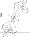
- a rice grain 2 moving along a falling trajectory Z while falling through the chute is imaged by two cameras 3 (front camera 3a and a rear camera 3b) from front and rear sides with respect to the rice grain 2.
- the rice grain 2 bounces on the chute.
- the rice grain 2 can be imaged at a detection position P' offset on the side of the front camera 3a or a detection position P" offset on the side of the rear camera 3b, with respect to an ideal detection position P at which an optical axis O of the front camera 3a intersects the falling trajectory Z (see FIG. 8 ).
- each of the reference signs 9a, 9a denotes a background for one of the cameras opposed thereto.
- the object surface of the rice grain 2 deviating to the position P' illustrated in FIG. 8 is not illuminated with light.
- the rice grain undesirably deviates to the position P" on the side of the rear camera 3b.
- the object surface of the rice grain also fails to be present on optical paths of light rays reflected by the reflectors, and the rice grain is not illuminated with light.
- the problem during imaging of the front side of the rice grain by the front camera 3a is also applied to imaging of the rear side of the rice grain by the rear camera 3b.
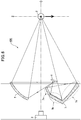
- the sixth embodiment illustrated in FIG. 9 has been conceived to solve the influence on a detection image arising from a positional deviation of the object surface caused by a phenomenon that a to-be-detected object falls down while bouncing on the chute, or the like.
- Each of a first reflector 14 and a second reflector 15 in the illuminating device according to the sixth embodiment has a plurality of concave curved surface portions (e.g., two ellipsoidal concave curved surfaces) which are different in terms of curvature.
- the plurality of concave curved surface portions comprises at least a first concave curved surface portion defined by a first curvature, and a second concave curved surface portion defined by a second curvature.
- the remaining components are the same as those in the first embodiment.
- the following description will be made about an effect of the concave curved mirror having the "plurality of concave curved surface portions".
- the sixth embodiment is characterized in that the reflectors 14, 15 each having the plurality of concave curved surface portions are used to create a width in a focusing region, as shown in FIG. 9 .
- the first reflector 14 has a first concave curved surface portion 14a and a second concave curved surface portion 14b.
- the second reflector 15 has a first concave curved surface portion 15a and a second concave curved surface portion 15b.
- Each of the first concave curved surface portion 14a and the second concave curved surface portion 14b of the first reflector 14 is configured to reflect light rays from the illumination light source 14a to illuminate the rice grain from therebelow.
- a focusing position of light rays reflected by the first concave curved surface portion 14a is not identical to a focusing position of light rays reflected by the second concave curved surface portion 14b. This is just because the surface curvature defining the first concave curved surface portion 14a is different from the surface curvature defining the second concave curved surface portion 14b.
- the surface curvature of the first concave curved surface portion 14a is designed such that the reflected light rays are focused over a given range on the side rearward of the ideal detection position P of the rice grain 2 (in FIG. 9 , in a direction coming away from the camera 3).
- the surface curvature of the second concave curved surface portion 14b is designed such that the light rays reflected by the second concave curved surface portion 14b are also focused over a given range on the side forward of the ideal detection position P of the rice grain 2 (in FIG.
- the surface curvatures of the second reflector 15 are designed such that each set of light rays reflected by a respective one of the first concave curved surface portion 15a and the second concave curved surface portion 15b of the second reflector 15 are focused over a given range on the side rearward or forward of the ideal detection position P of the rice grain 2.
- FIG. 9 shows an example in which the illumination range by the first concave curved surface portion 14a does not overlap the illumination range by the second concave curved surface portion 14b.
- the two illumination ranges may partially overlap each other. That is, the curvatures of the two concave curved surface portions may be adjusted such that the sets of light rays reflected by the first concave curved surface portion and the second concave curved surface portion partially overlay each other to illuminate a part of object surfaces of the rice grain 2 and a rice grain 2' or 2" with the reflected light from the two concave curved surface portions.
- each of the first reflector 14 and the second reflector 15 having a focusing property, it becomes possible to realize illumination covering the entire front half of a rice grain, not only when the rice grain is moving just along an ideal falling trajectory, but also when the rice grain is falling down while deviating from the falling trajectory Z in the front-rear direction, like the rice grain 2' or 2".
- FIG. 9 shows only a region on the side of the front camera 3a, the same is completely applied to illumination for the entire rear half of the rice grain by the rear camera 3b. Thus, description thereof will be omitted.
- the concept of controlling the focusing position using a first reflector 24 and a second reflector 25 in the seventh embodiment illustrated in FIG. 10 is basically the same as that in the sixth embodiment.
- a difference is that the shape of each of the first and second reflectors 14, 15 in the sixed embodiment is a concave curved shape formed by combining a plurality of concave curved surface portions having different curvatures, and each of the concave curved surface portions is designed such that the focusing position thereof is located forward or rearward of the rice grain, whereas each of the first and second reflectors 24, 25 in the seventh embodiment is formed to have a concave free-curved shape, and the width of the focusing region is created by the curvature at an arbitrary position on a concave free-curved surface thereof.
- the concept of controlling the focusing position using a first reflector 34 and a second reflector 35 in the eighth embodiment illustrated in FIG. 11 is basically the same as that in the sixth embodiment.
- a difference is that the shape of each of the first and second reflectors 14, 15 in the sixed embodiment is a concave curved shape formed by combining a plurality of concave curved surface portions having different curvatures, and each of the concave curved surface portions is designed such that the focusing position thereof is located forward or rearward of the rice grain, whereas, in each of the first and second reflectors 34, 35 in the eighth embodiment, the width of the focusing region is created by forming the concave curved surface into a mirror surface shape approximated by a plurality of planar surfaces.
- FIG. 12 shows optical paths of light rays from an illumination light source in one example where the technical idea regarding the first and second reflectors 14, 15 (reflectors each having a plurality of concave curved surface portions which are different in terms of curvature) in the sixth embodiment is applied to the illuminating device according to the first embodiment. It should be understood that this technical idea is also applicable to: the second reflector 5 in FIG. 3(A) and the first and second reflectors 4, 5 in FIG. 3(B) which are the modifications of the second embodiment; and the first and second reflectors 4, 5 in each of the configurations illustrated in FIG. 4 as the third embodiment and FIG. 5(A) as the modification thereof.
- the illuminating devices according to the sixth to ninth embodiments are free from the problem that a detection image becomes dark or a shadow appears in the image, even if the position of the object surface of each rice grain somewhat deviates. This makes it possible to produce a sorting machine free from deterioration in detection accuracy.
- the reflectors in the sixth to ninth embodiments provide an excellent effect of being able to control the distribution of luminous energy with respect to each incident angle of a light ray traveling toward a to-be-detected object.
- the use of the reflector defined by the concave curved surface as shown in the sixth to ninth embodiments provides a feature of being able to perform illumination covering the entire object surface of a to-be-detected object, while adequately controlling the distribution of luminous energy even when the to-be-detected object does not fall down along an assumed ideal trajectory.
- an advantage of composing the reflector of the first concave curved surface portion and the second concave curved surface portion includes a capability of controlling luminous energy values from the concave curved surface portions to become different from each other.
- a surface area ratio between the first concave curved surface portion 14a or 15a and the second concave curved surface portion 14b or 15b illustrated in FIG. 9 is changed for the purpose of explaining the luminous energy control.
- FIGS. 9 to 12 show an example in which each of the first reflector 14, 24 or 34 and the second reflector 15, 25 or 35 is configured to spread the focusing position such that an extended region including a to-be-detected object becomes an illumination range.
- the present invention is not intended to exclude a configuration in which this technical idea is applied to only one of the first and second reflectors.
- the reflector is defined by the two concave curved surface portions (the first concave curved surface portion and the second concave curved surface portion).
- the present invention is not limited thereto. That is, the reflector may have a larger number of concave curved surface portions.
- the entire concave curved surface may be composed of three concave curved surface portions.
- angles ⁇ 1 , ⁇ 2 , ⁇ 3 , ⁇ 4 , ⁇ 1 ', ⁇ 2 ', ⁇ 3 ', ⁇ 4 ' may be set such that luminous energy reflected by each of the first concave curved surface portions 14a, 15a becomes equal to or less than energy reflected by each of the second concave curved surface portions 14b, 15b, and the concave curved surface may be formed such that each of the surface portions has a surface area corresponding thereto.
- a light-emitting face of an illumination light source may be undesirably reflected on the detection image (see the area surrounded by the dotted line in FIG. 15 ).
- the illumination light source is constructed by using a plurality of LED chips as light emitters, the array of light emitters are identified on the surface of the to-be-detected object in a recognizable manner, and light indicative of the undesirable reflection is superimposed on illumination light.
- a concave curved mirror for each of the first reflector and the second reflector is formed by concavely curvedly bending an aluminum rolled material such that lines on the surface thereof extending in a rolling direction become longitudinal lines.
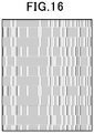
- the concave curved mirror is formed by adding a large number of lines like those obtained through hairline processing, to an aluminum plate having a mirror surface, in a longitudinal direction (see FIG. 16 ), and then concavely curvedly bending the aluminum plate.
- the concave curved mirror is formed by fabricating longitudinal lines on a metal mold to allow a reflection surface of the concave curved mirror to be formed with longitudinal grooves, and then vapor-depositing aluminum on the surface of the metal mold having the longitudinal lines.
- each of the first reflector and the second reflector produces an effect of allowing light emitted from the illumination light source and then reflected by each of the concave curved mirrors to be laterally scattered. This makes it possible to laterally disperse the refraction of the light-emitting face of the LED chips on the surface of the to-be-detected object.
- dimples (depressions) having an arbitrarily-set aspect ratio may be formed instead of lines as mentioned above.
- luminous energy directed toward the to-be-detected object is significantly reduced.
- the effect as means to avoid the undesirable reflection indicative of the LED chips presence is significantly large.
- any light emitter may be used as the illumination light source.
- an LED chip in a conventional illuminating device, a large number of LED chips are used, and a large number of corresponding driving circuits are used to detect LED burn-out by means of lighting. Thus, it is necessary to spend a lot of cost for the LED chips and the LED driving circuits.
- the LED chips can be turn on by using a parallel circuit to reduce the number of the LED driving circuits, thereby achieving a reduction in cost. Hoverer, in this case, there is a problem that the LED burn-out cannot be detected.
- one illumination light source can be sharedly used for upper and lower illuminations, so that the number of not only the illumination light sources but also the LED chips can be simply reduced to one-half, and the number of the LED driving circuits can also be reduced. Therefore, it becomes possible to realize detection of the LED burn-out while facilitating a reduction in cost.
- luminous energy of illumination light onto a to-be-detected object is two times or more that of a conventional illuminating device using no reflector.
- a part of the illumination light source composed of white LEDs can be replaced by an IR LED.
- light having a plurality of wavelengths can be simultaneously emitted by one illuminating device.
- luminous energy equal to or greater than that of the conventional illuminating device can be obtained using a less number of chips.
- a cost reduction effect when using an IR LED more costly than a white LED is significantly large.
- the present invention is not necessarily limited thereto.
- grains other than rice grains such as soybeans; granular solids such as coffee beans or seeds; green tea leafs; tablets; and resin pellets containing color paint, which are obtained by processing a synthetic resin such as a bumper of an automobile into a pellet shape in a recycle process.
- the to-be-detected objects are, e.g., sheet-shaped or film-shaped objects stacked on a conveyer
- the granular objects such as rice grains
Landscapes
- Life Sciences & Earth Sciences (AREA)
- General Physics & Mathematics (AREA)
- Health & Medical Sciences (AREA)
- Chemical & Material Sciences (AREA)
- Physics & Mathematics (AREA)
- Immunology (AREA)
- General Health & Medical Sciences (AREA)
- Biochemistry (AREA)
- Analytical Chemistry (AREA)
- Pathology (AREA)
- Engineering & Computer Science (AREA)
- General Engineering & Computer Science (AREA)
- Botany (AREA)
- Wood Science & Technology (AREA)
- Food Science & Technology (AREA)
- Medicinal Chemistry (AREA)
- Spectroscopy & Molecular Physics (AREA)
- Investigating Materials By The Use Of Optical Means Adapted For Particular Applications (AREA)
- Sorting Of Articles (AREA)
Applications Claiming Priority (2)
| Application Number | Priority Date | Filing Date | Title |
|---|---|---|---|
| JP2018031560A JP6909407B2 (ja) | 2018-02-26 | 2018-02-26 | 選別機又は検査機用照明装置 |
| PCT/JP2019/007217 WO2019164009A1 (ja) | 2018-02-26 | 2019-02-26 | 選別機又は検査機用照明装置 |
Publications (2)
| Publication Number | Publication Date |
|---|---|
| EP3761011A1 true EP3761011A1 (de) | 2021-01-06 |
| EP3761011A4 EP3761011A4 (de) | 2021-12-08 |
Family
ID=67688133
Family Applications (1)
| Application Number | Title | Priority Date | Filing Date |
|---|---|---|---|
| EP19757866.9A Withdrawn EP3761011A4 (de) | 2018-02-26 | 2019-02-26 | Beleuchtungsvorrichtung für sortiermaschine oder inspektionsmaschine |
Country Status (9)
| Country | Link |
|---|---|
| US (1) | US20210003509A1 (de) |
| EP (1) | EP3761011A4 (de) |
| JP (1) | JP6909407B2 (de) |
| KR (1) | KR20200123147A (de) |
| CN (1) | CN111742213A (de) |
| AU (1) | AU2019224509A1 (de) |
| BR (1) | BR112020017021A2 (de) |
| TW (1) | TWI719410B (de) |
| WO (1) | WO2019164009A1 (de) |
Cited By (3)
| Publication number | Priority date | Publication date | Assignee | Title |
|---|---|---|---|---|
| US20210003509A1 (en) * | 2018-02-26 | 2021-01-07 | Satake Corporation | Illuminating device for a sorting or inspecting machine |
| SE2150693A1 (en) * | 2021-05-31 | 2022-12-01 | Bomill Ab | Object sorting device comprising an illumination unit and pivotable mirrors |
| EP4246131A1 (de) * | 2022-03-14 | 2023-09-20 | Bühler UK Limited | Beleuchtung für eine optische überwachungsvorrichtung |
Families Citing this family (3)
| Publication number | Priority date | Publication date | Assignee | Title |
|---|---|---|---|---|
| EP3822616A1 (de) * | 2019-11-15 | 2021-05-19 | Roche Diagnostics GmbH | Vorrichtung zum abbilden eines laborprobenbehälters unter verwendung gekrümmter reflektoren oder streuer |
| JP7440044B2 (ja) * | 2022-02-08 | 2024-02-28 | ユーシーシー上島珈琲株式会社 | コーヒー豆類の良品識別機能を備える良品検査システムおよび良品検査方法 |
| KR102935628B1 (ko) | 2023-09-22 | 2026-03-09 | (주)아이씨디 | 반사광학계를 이용한 바이오입자 및 미세먼지 검출 장치 |
Family Cites Families (22)
| Publication number | Priority date | Publication date | Assignee | Title |
|---|---|---|---|---|
| JPS6015052B2 (ja) * | 1977-10-12 | 1985-04-17 | キヤノン株式会社 | スリツト照明装置 |
| JPS5899736A (ja) * | 1981-12-08 | 1983-06-14 | Matsushita Electric Works Ltd | 表面欠陥検出装置 |
| JPS61171044U (de) * | 1985-04-10 | 1986-10-23 | ||
| JPH0231009A (ja) * | 1988-04-22 | 1990-02-01 | Kyokuto Kaihatsu Kogyo Co Ltd | 伸縮シリンダの緩衝装置 |
| JPH10332567A (ja) * | 1997-05-27 | 1998-12-18 | Lion Corp | 粒子の混合比測定方法及び装置 |
| JP2002170404A (ja) * | 2000-11-29 | 2002-06-14 | Tb Optical Co Ltd | ライトガイド用照明光源 |
| JP2002310626A (ja) * | 2001-04-18 | 2002-10-23 | Omron Corp | 照明装置 |
| JP2005156357A (ja) * | 2003-11-26 | 2005-06-16 | Kyoto Denkiki Kk | ツイン蛍光灯を用いた線状照明装置 |
| JP4805534B2 (ja) * | 2003-12-24 | 2011-11-02 | ダックエンジニアリング株式会社 | ワーク検査装置 |
| JP4599477B2 (ja) * | 2004-01-30 | 2010-12-15 | 株式会社パル技研 | 欠点検出装置用高照度照明装置および欠点検出装置 |
| JP4488873B2 (ja) * | 2004-03-02 | 2010-06-23 | シーシーエス株式会社 | 光照射装置 |
| JP4675120B2 (ja) * | 2005-02-28 | 2011-04-20 | 株式会社クボタ | 粒状体選別装置 |
| JP4915129B2 (ja) | 2006-04-17 | 2012-04-11 | 株式会社サタケ | 色彩選別機 |
| CN101482689A (zh) * | 2009-02-12 | 2009-07-15 | 复旦大学 | 超薄背投光学系统 |
| DE202009013555U1 (de) * | 2009-10-07 | 2010-02-04 | Ldv-Systeme Gmbh | Einrichtung zur Ausleuchtung der Oberfläche eines Bauteils |
| JP2012002762A (ja) * | 2010-06-18 | 2012-01-05 | Omron Corp | カラーセンサ |
| CN103907013B (zh) * | 2011-11-09 | 2016-12-28 | 株式会社久保田 | 粒状体检查装置 |
| JP6179752B2 (ja) * | 2012-12-28 | 2017-08-16 | 株式会社サタケ | 検査装置 |
| JP6061086B2 (ja) * | 2013-03-08 | 2017-01-18 | 株式会社リコー | 光走査装置及び画像形成装置 |
| JP2015187564A (ja) * | 2014-03-26 | 2015-10-29 | 株式会社日立ハイテクノロジーズ | 赤外線検査装置 |
| JP2017203759A (ja) * | 2016-05-13 | 2017-11-16 | 株式会社キーエンス | 画像処理センサ |
| JP6909407B2 (ja) * | 2018-02-26 | 2021-07-28 | 株式会社サタケ | 選別機又は検査機用照明装置 |
-
2018
- 2018-02-26 JP JP2018031560A patent/JP6909407B2/ja active Active
-
2019
- 2019-02-25 TW TW108106229A patent/TWI719410B/zh not_active IP Right Cessation
- 2019-02-26 BR BR112020017021-6A patent/BR112020017021A2/pt not_active Application Discontinuation
- 2019-02-26 EP EP19757866.9A patent/EP3761011A4/de not_active Withdrawn
- 2019-02-26 US US16/975,277 patent/US20210003509A1/en not_active Abandoned
- 2019-02-26 AU AU2019224509A patent/AU2019224509A1/en not_active Abandoned
- 2019-02-26 WO PCT/JP2019/007217 patent/WO2019164009A1/ja not_active Ceased
- 2019-02-26 CN CN201980014684.1A patent/CN111742213A/zh not_active Withdrawn
- 2019-02-26 KR KR1020207025271A patent/KR20200123147A/ko not_active Withdrawn
Cited By (6)
| Publication number | Priority date | Publication date | Assignee | Title |
|---|---|---|---|---|
| US20210003509A1 (en) * | 2018-02-26 | 2021-01-07 | Satake Corporation | Illuminating device for a sorting or inspecting machine |
| SE2150693A1 (en) * | 2021-05-31 | 2022-12-01 | Bomill Ab | Object sorting device comprising an illumination unit and pivotable mirrors |
| WO2022255919A1 (en) * | 2021-05-31 | 2022-12-08 | Bomill Ab | Object sorting device comprising an illumination unit and pivotable mirrors |
| SE544932C2 (en) * | 2021-05-31 | 2023-01-10 | Bomill Ab | Object sorting device comprising an illumination unit and pivotable mirrors |
| EP4246131A1 (de) * | 2022-03-14 | 2023-09-20 | Bühler UK Limited | Beleuchtung für eine optische überwachungsvorrichtung |
| WO2023174579A1 (en) * | 2022-03-14 | 2023-09-21 | Bühler Uk Ltd. | Lighting for an optical monitoring apparatus |
Also Published As
| Publication number | Publication date |
|---|---|
| CN111742213A (zh) | 2020-10-02 |
| US20210003509A1 (en) | 2021-01-07 |
| AU2019224509A1 (en) | 2020-09-24 |
| JP6909407B2 (ja) | 2021-07-28 |
| BR112020017021A2 (pt) | 2020-12-15 |
| TWI719410B (zh) | 2021-02-21 |
| TW201944058A (zh) | 2019-11-16 |
| JP2019148431A (ja) | 2019-09-05 |
| EP3761011A4 (de) | 2021-12-08 |
| KR20200123147A (ko) | 2020-10-28 |
| WO2019164009A1 (ja) | 2019-08-29 |
Similar Documents
| Publication | Publication Date | Title |
|---|---|---|
| US20210003509A1 (en) | Illuminating device for a sorting or inspecting machine | |
| US7339660B1 (en) | Illumination device for product examination | |
| JP6812411B2 (ja) | 車両用灯具、車両用灯具制御システムおよびこれらを備えた車両 | |
| US6598994B1 (en) | Multi-angle inspection of manufactured products | |
| US6161941A (en) | Light array system and method for illumination of objects imaged by imaging systems | |
| CN104100902B (zh) | 用于机动车照明装置的光模块 | |
| US6013887A (en) | Color-sorting machine for granular materials | |
| CN110166702B (zh) | 捕获图像数据的相机和方法 | |
| US20090213607A1 (en) | Vehicle lighting device | |
| CN102734732B (zh) | 具有半导体光源的机动车头灯 | |
| US10260726B2 (en) | Vehicle lamp device | |
| JP5795498B2 (ja) | 粒状体選別装置 | |
| US8562191B2 (en) | Vehicle light | |
| US20060037892A1 (en) | Apparatus for optically analyzing products such as fruit having indirect illumination | |
| KR20030038515A (ko) | Ccd 선형 센서로 구성되는 광검출 장치를 갖는입상체용 색선별 장치 | |
| CN103307492A (zh) | Led聚光光源及基于该led聚光光源的物料分选装置 | |
| US6936784B2 (en) | Illumination source for sorting machine | |
| US7306351B2 (en) | Lens for side emitting LED device | |
| US11047543B1 (en) | Narrow aperture light system | |
| WO2013069736A1 (ja) | 粒状体検査装置 | |
| CN104654169B (zh) | 车辆用灯具 | |
| JP7282021B2 (ja) | 色彩選別機 | |
| WO2010008303A1 (en) | Improved method and apparatus for article inspection | |
| US4900916A (en) | System employing preconditioned radiation for detecting defects in transparent objects | |
| JP2006234744A (ja) | 粒状体選別装置 |
Legal Events
| Date | Code | Title | Description |
|---|---|---|---|
| STAA | Information on the status of an ep patent application or granted ep patent |
Free format text: STATUS: THE INTERNATIONAL PUBLICATION HAS BEEN MADE |
|
| PUAI | Public reference made under article 153(3) epc to a published international application that has entered the european phase |
Free format text: ORIGINAL CODE: 0009012 |
|
| STAA | Information on the status of an ep patent application or granted ep patent |
Free format text: STATUS: REQUEST FOR EXAMINATION WAS MADE |
|
| 17P | Request for examination filed |
Effective date: 20200916 |
|
| AK | Designated contracting states |
Kind code of ref document: A1 Designated state(s): AL AT BE BG CH CY CZ DE DK EE ES FI FR GB GR HR HU IE IS IT LI LT LU LV MC MK MT NL NO PL PT RO RS SE SI SK SM TR |
|
| AX | Request for extension of the european patent |
Extension state: BA ME |
|
| DAV | Request for validation of the european patent (deleted) | ||
| DAX | Request for extension of the european patent (deleted) | ||
| A4 | Supplementary search report drawn up and despatched |
Effective date: 20211105 |
|
| RIC1 | Information provided on ipc code assigned before grant |
Ipc: F21Y 115/10 20160101ALI20211029BHEP Ipc: G01N 21/85 20060101ALI20211029BHEP Ipc: F21V 7/09 20060101ALI20211029BHEP Ipc: B07C 5/342 20060101ALI20211029BHEP Ipc: G01N 21/84 20060101AFI20211029BHEP |
|
| STAA | Information on the status of an ep patent application or granted ep patent |
Free format text: STATUS: EXAMINATION IS IN PROGRESS |
|
| STAA | Information on the status of an ep patent application or granted ep patent |
Free format text: STATUS: THE APPLICATION HAS BEEN WITHDRAWN |
|
| 17Q | First examination report despatched |
Effective date: 20230306 |
|
| 18W | Application withdrawn |
Effective date: 20230314 |