EP3761025B1 - Procédé de fonctionnement d'un dispositif de détection de gaz et dispositif de détection de gaz - Google Patents
Procédé de fonctionnement d'un dispositif de détection de gaz et dispositif de détection de gaz Download PDFInfo
- Publication number
- EP3761025B1 EP3761025B1 EP20180576.9A EP20180576A EP3761025B1 EP 3761025 B1 EP3761025 B1 EP 3761025B1 EP 20180576 A EP20180576 A EP 20180576A EP 3761025 B1 EP3761025 B1 EP 3761025B1
- Authority
- EP
- European Patent Office
- Prior art keywords
- value
- sensor circuit
- gas sensor
- gas
- gas sensing
- Prior art date
- Legal status (The legal status is an assumption and is not a legal conclusion. Google has not performed a legal analysis and makes no representation as to the accuracy of the status listed.)
- Active
Links
Images

Classifications
-
- G—PHYSICS
- G01—MEASURING; TESTING
- G01N—INVESTIGATING OR ANALYSING MATERIALS BY DETERMINING THEIR CHEMICAL OR PHYSICAL PROPERTIES
- G01N33/00—Investigating or analysing materials by specific methods not covered by groups G01N1/00 - G01N31/00
- G01N33/0004—Gaseous mixtures, e.g. polluted air
- G01N33/0009—General constructional details of gas analysers, e.g. portable test equipment
- G01N33/007—Arrangements to check the analyser
-
- G—PHYSICS
- G01—MEASURING; TESTING
- G01N—INVESTIGATING OR ANALYSING MATERIALS BY DETERMINING THEIR CHEMICAL OR PHYSICAL PROPERTIES
- G01N27/00—Investigating or analysing materials by the use of electric, electrochemical, or magnetic means
- G01N27/02—Investigating or analysing materials by the use of electric, electrochemical, or magnetic means by investigating impedance
- G01N27/04—Investigating or analysing materials by the use of electric, electrochemical, or magnetic means by investigating impedance by investigating resistance
- G01N27/045—Circuits
-
- G—PHYSICS
- G01—MEASURING; TESTING
- G01N—INVESTIGATING OR ANALYSING MATERIALS BY DETERMINING THEIR CHEMICAL OR PHYSICAL PROPERTIES
- G01N33/00—Investigating or analysing materials by specific methods not covered by groups G01N1/00 - G01N31/00
- G01N33/0004—Gaseous mixtures, e.g. polluted air
- G01N33/0006—Calibrating gas analysers
-
- G—PHYSICS
- G01—MEASURING; TESTING
- G01N—INVESTIGATING OR ANALYSING MATERIALS BY DETERMINING THEIR CHEMICAL OR PHYSICAL PROPERTIES
- G01N33/00—Investigating or analysing materials by specific methods not covered by groups G01N1/00 - G01N31/00
- G01N33/0004—Gaseous mixtures, e.g. polluted air
- G01N33/0009—General constructional details of gas analysers, e.g. portable test equipment
- G01N33/0027—General constructional details of gas analysers, e.g. portable test equipment concerning the detector
- G01N33/0031—General constructional details of gas analysers, e.g. portable test equipment concerning the detector comprising two or more sensors, e.g. a sensor array
-
- G—PHYSICS
- G01—MEASURING; TESTING
- G01N—INVESTIGATING OR ANALYSING MATERIALS BY DETERMINING THEIR CHEMICAL OR PHYSICAL PROPERTIES
- G01N33/00—Investigating or analysing materials by specific methods not covered by groups G01N1/00 - G01N31/00
- G01N33/0004—Gaseous mixtures, e.g. polluted air
- G01N33/0009—General constructional details of gas analysers, e.g. portable test equipment
- G01N33/0062—General constructional details of gas analysers, e.g. portable test equipment concerning the measuring method or the display, e.g. intermittent measurement or digital display
- G01N33/0063—General constructional details of gas analysers, e.g. portable test equipment concerning the measuring method or the display, e.g. intermittent measurement or digital display using a threshold to release an alarm or displaying means
Definitions
- the description relates to gas sensors, preferably MEMS metal oxide (MOX) gas sensors.
- MOX metal oxide
- One or more embodiments may relate to methods of performing a self-diagnosis procedure for checking the health state of a gas sensor.
- Gas sensors have been playing a significant role in the development of personal and/or industrial electronic devices.
- gas sensors with small size, low power consumption, ease of integration, high degree of functionality and good performance may facilitate the implementation of innovative functions in smart phones, personal electronic devices, medical consumer applications and the like.
- Gas sensors may also be involved in life-critical applications such as, e.g., air-bags, biosensors, aerospace devices and the like.
- gas sensors may suffer from performance degradation over time, i.e., the health state of the sensor may be affected by contamination and/or poisoning effects, aging effects, clogged holes, and other causes. Therefore, checking the health state of a gas sensor (e.g., periodically) may be beneficial to avoid malfunctions of the sensor itself, e.g., detection of false positives and/or false negatives (i.e., missed detections). Also the response time of the gas sensor may be affected by contamination effects, poisoning effects, aging effects, etc.
- some MEMS gas sensor may involve periodic performance verification and, if necessary, re-calibration as a result of performance degradation being detected.
- verification of the performance of a MEMS gas sensor may involve computing the accuracy error of the sensor over time by comparing the output of the sensor under test with the output of a reference professional instrument, e.g., at regular time intervals.
- re-calibration of sensor offset and/or sensor gain may be performed, e.g., by using a dedicated software or interface that runs on a microcontroller which controls operation of the sensor.
- some high-end MEMS gas sensors may include built-in mechanisms for providing improved robustness and self-diagnosis capabilities, as well as compensation of performance degradation over time (often due to contaminants, poisoning effects or aging effects), at the cost of increased device complexity, size and manufacturing cost (e.g., because of a dedicated design of both the MEMS gas sensor itself and the ASIC coupled thereto).
- conventional sensors having self-diagnosis capabilities may involve being operated under controlled conditions (e.g., in a controlled environment) during execution of a self-diagnosis procedure, which may be undesirable insofar as:
- Document GB 2435099 A discloses a sensor arrangement for detecting a reactive component of a gas mixture.
- the sensor arrangement comprises an enclosure which is selectively moveable between an open configuration, in which an interior of the enclosure may communicate with surrounding gases, and a closed configuration, in which the interior of the enclosure is substantially isolated from the surrounding gases.
- the sensor arrangement comprises a catalytic sensor located within the enclosure and adapted to detect the presence of the reactive component.
- the sensor arrangement comprises a processing arrangement operable to compensate for variations in the sensitivity of the catalytic sensor and to place the enclosure in the closed configuration in response to the fulfillment of a predetermined detection level.
- Document GB 2435099 A also discloses means to determine a time constant of the decay of a signal output by the catalytic sensor, or another parameter related to the rate of decay, following the isolation of the catalytic sensor; and from the time constant or other parameter, calculate the sensitivity of the catalytic sensor to the presence of the reactive element.
- the calculated sensitivity is compared to a reference sensitivity. If the calculated sensitivity differs from the reference sensitivity by less than a first threshold amount, a sensitivity compensation is applied. If the calculated sensitivity differs from the reference sensitivity by more than the first threshold amount, a warning indication is provided.
- the document US2006289400 discloses a gas sensor with a self-diagnosis unit which allows issuing a warning message when the sensor does not work correctly. The diagnosis is based on the slope of the sensor's voltage signal.
- solutions are desirable which may provide improved self-diagnosis methods of gas sensors.
- An object of one or more embodiments is to contribute in providing such improved solutions.
- One or more embodiments may relate to a corresponding gas sensing device.
- One or more embodiments may provide a method of operating a gas sensing device, wherein the gas sensing device may comprise a gas sensor circuit comprising a resistive gas sensing element, and a control circuit coupled to the gas sensor circuit, the method comprising:
- one or more embodiments may not involve interrupting or stopping the operation of the tool or equipment where a gas sensor is installed in order to perform a self-diagnosis procedure of the gas sensor.
- a self-diagnosis procedure may be carried out independently from the current operating conditions (e.g., environmental conditions) of the tool or equipment where the gas sensor is installed.
- references to "an embodiment” or “one embodiment” in the framework of the present description is intended to indicate that a particular configuration, structure, or characteristic described in relation to the embodiment is comprised in at least one embodiment.
- phrases such as “in an embodiment” or “in one embodiment” that may be present in one or more points of the present description do not necessarily refer to one and the same embodiment.
- particular conformations, structures, or characteristics may be combined in any adequate way in one or more embodiments.
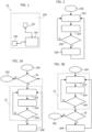
- FIG. 1 is a system block diagram exemplary of a gas sensing device 10 according to embodiments.
- the gas sensing device 10 may comprise a printed circuit board (PCB) 100 providing mechanical support and electrical connections for:
- PCB printed circuit board
- the device available with companies of the STMicroelectronics group under the trade designation GHT25S is exemplary of a MEMS gas sensor circuit 102 suitable for use in one or more embodiments.
- the MEMS gas sensor circuit 102 may comprise at least one semiconductor die which hosts:
- a gas sensing device 10 may be used in various applications to detect the concentration of a certain gas (e.g., a volatile organic compound such as carbon monoxide, carbon dioxide, methane and the like) as an indicator of possible failure of a system or component, for instance in a medical or industrial tool or equipment, or also in consumer electronics goods.
- a certain gas e.g., a volatile organic compound such as carbon monoxide, carbon dioxide, methane and the like
- An alert signal may be issued by the gas sensing device 10 as a result of said concentration detected by the MEMS gas sensor circuit 102 reaching a certain threshold value.
- Figure 2 is a flow diagram exemplary of a possible operation flow of a conventional gas sensing device 10 which does not implement any self-diagnosis procedure.
- the operation flow of the gas sensing device 10 may comprise:
- the calibration function(s) of the gas sensing device 10 may be generated at the manufacturing level of the MEMS gas sensor circuit 102 and stored in a dedicated memory area (e.g., provided on the printed circuit board 100).
- a dedicated memory area e.g., provided on the printed circuit board 100.
- Such memory area may be of a re-writable type, insofar as re-calibration of the MEMS gas sensor circuit 102 may be performed via software by modifying the calibration function(s).
- an alert signal may be issued as a result of the computed gas concentration being higher than a certain threshold (e.g., in case the gas sensor is used to detect flammable gases whose high concentration may be hazardous) or lower than a certain threshold (e.g., in case the gas sensor is used in a medical device to detect oxygen concentration which should not fall below a certain limit).
- a certain threshold e.g., in case the gas sensor is used to detect flammable gases whose high concentration may be hazardous
- a certain threshold e.g., in case the gas sensor is used in a medical device to detect oxygen concentration which should not fall below a certain limit
- One or more embodiments as exemplified in the block diagrams of Figures 3A and 3B may provide a method of operating a gas sensing device 10 which comprises performing a diagnosis procedure to verify the health state of the MEMS gas sensor circuit 102 before issuing an alert signal.
- the operation flow exemplified in Figure 3A may comprise, after a start step 200, performing a diagnostic procedure 30 of the MEMS gas sensor circuit 102.
- a diagnostic procedure 30 of the MEMS gas sensor circuit 102 As a result of a negative outcome (N) of such diagnostic procedure 30, i.e., in case the MEMS gas sensor circuit 102 is found out to be faulty or damaged, the operation flow terminates at a step 302 in a "fail" mode and flags the MEMS gas sensor circuit 102 as damaged.
- step 208 operation may resume either from step 30 (i.e., the diagnostic procedure 30 may be repeated after each alert signal issued) of from step 202 (i.e., the diagnostic procedure 30 is performed only once at start-up of the gas sensing device 10).
- an operation flow as exemplified in Figure 3B may comprise, after a start step 200, performing the main execution thread 32 of the gas sensing device 10, i.e., steps 202, 204 and 206.
- the operation flow may comprise performing the diagnostic procedure 30 of the MEMS gas sensor circuit 102.
- N negative outcome
- the operation flow terminates at a step 302 in a "fail" mode by flagging the MEMS gas sensor circuit 102 as damaged.
- step 208 issuing an alert signal. After step 208, operation may resume from step 202.
- some embodiments may comprise performing the diagnostic procedure 30 after the start step 200 (e.g., at start-up of the gas sensing device 10 and/or after issuing an alert signal), and other embodiments may comprise performing the diagnostic procedure 30 upon a positive outcome of the step 206 (e.g., before issuing an alert signal).
- Further embodiments may comprise performing the diagnostic procedure 30 both after the start step 200 and upon a positive outcome of the step 206, e.g., to increase robustness of the diagnosis feature. Still further embodiments may comprise performing the diagnostic procedure 30 periodically during operation of the gas sensing device 10 (e.g., every N executions of the main thread 32, with N being an arbitrary integer value possibly configurable by the user, or at regular time intervals).
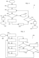
- Figure 4 is a block diagram exemplary of the operation flow of a diagnostic procedure 30 in one or more embodiments.
- a diagnostic procedure 30 as exemplified in Figure 4 may comprise the following steps:
- the correction mechanism triggered at step 314 may comprise increasing by a certain value the driving current of the heating resistor in the MEMS gas sensor circuit 102, thereby increasing the temperature of the MEMS micro-hotplate hosting the sensing element of the gas sensor (e.g., a metal oxide layer).
- the checking act 318 may be performed directly after the classification step 308 in case of outcome Y of the classification step 308, with the steps 314 and/or 316 possibly performed only upon negative outcome (N) of step 318.
- a diagnostic procedure 30 as exemplified in Figure 4 may terminate with two possible outcomes (as exemplified also in Figures 3A and 3B ), namely:
- FIG. 5 is a block diagram exemplary of the operation flow of a health state check procedure 306 in one or more embodiments.
- the health state check procedure 306 may be performed as a state machine running in the MEMS gas sensor circuit 102 or by a microcontroller 104 coupled to the MEMS gas sensor circuit 102.
- a health state check procedure 306 as exemplified in Figure 5 may comprise the following steps:
- Figure 6 is exemplary of a power driving signal for the heating resistor in the MEMS gas sensor circuit 102 (e.g., a signal indicative of a current provided to the heating resistor) as may be applied in one or more embodiments during a health state check procedure 306.
- the driving signal provided to the heating resistor may comprise:
- Figures 7A, 7B and 7C are exemplary of possible behavior over time of the MEMS gas sensor response during a health state check procedure 306 in one or more embodiments.
- Figure 7A exemplifies the time behavior of the sensed signal Rs(t) (illustrated with dashed line) during the intervals T1, T2 and Toff of the driving signal of the heating resistor (illustrated with solid line);
- Figures 7B and 7C exemplify with greater detail the time behavior of the sensed signal Rs(t) during the intervals T1 and T2, respectively. It is therefore illustrated that the average slope and the final value of the signal Rs(t) during interval T1 of subsequent cycles may tend to a steady state condition after a certain number of cycles.
- the step 512 of processing the current calculated values of slope of the resistance signal Rs(t) and resistance Rs(t 1 ) may comprise, for instance, determining phase and magnitude of a vector in a polar diagram, said vector having components ⁇ Rs(t 1 ), slope (Rs (t))>.
- the checking act 514 may comprise, for instance, checking whether said phase and magnitude are approximately constant with respect to a previous cycle of the health state check procedure 306.
- the checking act 514 may comprise:
- the step 308 of classifying the MEMS gas sensor circuit 102 as faulty/damaged, degraded or correctly operating as a function of the values of the set of parameters computed with a health state check procedure 306 may comprise analyzing the trajectory and/or the final point reached by the vector having components ⁇ Rs(t 1 ), slope(Rs(t))> in a polar diagram.
- the step 308 may comprise classifying the MEMS gas sensor circuit 102 as a function of the phase of the final vector having components ⁇ Rs(t 1 ), slope (Rs(t))>.
- the sensor may be classified as:
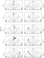
- Figure 8 is exemplary of different trajectories of the vector having components ⁇ Rs(t 1 ), slope(Rs(t))> as sensed during a health state check procedure 306 of respective different gas sensors S1 to S10.
- the following table illustrates the value of the phase of the respective vectors having components ⁇ Rs(t 1 ), slope(Rs(t))> once in steady state condition, and the corresponding sensitivity of the respective gas sensor: Sensor No.
- the phase of the vector having components ⁇ Rs(t 1 ), slope(Rs(t))> at steady state, and/or the trajectory followed by said vector in the polar plane during the health state check procedure 306, may be indicative of the performance of the MEMS gas sensor circuit 102.
- sensors S1 to S3 may be classified as faulty/damaged (i.e., having a bad health state)
- sensors S4 and S5 may be classified as degraded (i.e., having a medium health state)
- sensors S6 to S10 may be classified as correctly operating (i.e., having a good health state).
- the diagnostic procedure 30 may be run by the MEMS gas sensor circuit 102 (e.g., by means of an internal state machine) at power-on and/or periodically, and the main execution thread of the microcontroller 104 may be interrupted as a result of the diagnostic procedure 30 terminating with outcome "MEMS gas sensor circuit 102 classified as faulty/damaged".
- one or more embodiments may not involve interrupting or stopping the operation of the tool or equipment where the gas sensing device 10 is installed for performing the diagnostic procedure 30, insofar as the diagnostic procedure 30 may be carried out independently from the current operating conditions of the tool or equipment where the gas sensing device 10 is installed (i.e., the diagnostic procedure 30 may not involve operating the gas sensing device 10 in a controlled environment or under controlled test conditions).
Landscapes
- Chemical & Material Sciences (AREA)
- Life Sciences & Earth Sciences (AREA)
- Health & Medical Sciences (AREA)
- Engineering & Computer Science (AREA)
- Analytical Chemistry (AREA)
- General Physics & Mathematics (AREA)
- Pathology (AREA)
- Physics & Mathematics (AREA)
- Immunology (AREA)
- Biochemistry (AREA)
- General Health & Medical Sciences (AREA)
- Combustion & Propulsion (AREA)
- Food Science & Technology (AREA)
- Medicinal Chemistry (AREA)
- Chemical Kinetics & Catalysis (AREA)
- Electrochemistry (AREA)
- Investigating Or Analyzing Materials By The Use Of Electric Means (AREA)
- Investigating Or Analyzing Materials By The Use Of Fluid Adsorption Or Reactions (AREA)
Claims (12)
- Procédé de mise en oeuvre d'un dispositif de détection de gaz (10), dans lequel le dispositif de détection de gaz (10) comprend :- un circuit de capteur de gaz (102) comprenant un élément de détection de gaz résistif et un élément chauffant résistif, et- un circuit de commande (104) couplé au circuit de capteur de gaz (102),le procédé comprenant les étapes suivantes :- recevoir (202) dans le circuit de commande (104) un signal du circuit de capteur de gaz (102), ledit signal représentant une valeur de résistance dudit élément de détection de gaz résistif ;- traiter (204) ledit signal reçu du circuit de capteur de gaz (102) pour calculer une valeur d'une concentration en gaz ;- réaliser une comparaison (206) de ladite valeur de concentration en gaz avec une certaine valeur de seuil et mettre le dispositif de détection de gaz (10) dans un état de délivrance de signal d'alerte (208) en fonction du résultat de ladite comparaison, dans lequel la mise du dispositif de détection de gaz (10) dans ledit état de délivrance de signal d'alerte (208) est conditionnée au résultat d'une procédure de diagnostic (30), la procédure de diagnostic comprenant les étapes suivantes :- appliquer une impulsion de courant (I1, I2) audit élément chauffant résistif ;- mesurer ledit signal reçu du circuit de capteur de gaz (102) en conséquence de l'application de ladite impulsion de courant (I1) ;- calculer (306), en fonction dudit signal reçu, une valeur de résistance dudit élément de détection de gaz résistif et une valeur de pente dudit signal reçu ;- classer (308) le circuit de capteur de gaz (102) en fonction de ladite valeur de résistance dudit élément de détection de gaz résistif et de ladite valeur de pente dudit signal reçu, dans une classe parmi une première classe, une deuxième classe et une troisième classe qui indiquent que le circuit de capteur de gaz (102) est respectivement en panne, dégradé ou fonctionne correctement ; eti) en conséquence du classement du circuit de capteur de gaz (102) dans ladite première classe, désactiver (302) la mise du dispositif de détection de gaz (10) dans ledit état de délivrance de signal d'alerte (208) ;ii) en conséquence du classement du circuit de capteur de gaz (102) dans ladite deuxième classe, déclencher une procédure de correction de sensibilité (314) du circuit de capteur de gaz (102) et répéter ladite procédure de diagnostic (30) ; etiii) en conséquence du classement du circuit de capteur de gaz (102) dans ladite troisième classe, valider la mise du dispositif de détection de gaz (10) dans ledit état de délivrance de signal d'alerte (208).
- Procédé selon la revendication 1, comprenant, en conséquence du classement du circuit de capteur de gaz (102) dans ladite première classe, la délivrance d'un signal de panne de capteur.
- Procédé selon la revendication 1 ou 2, dans lequel ladite procédure de correction de sensibilité (314) comprend le fait d'augmenter la puissance fournie audit élément chauffant résistif.
- Procédé selon l'une quelconque des revendications précédentes, dans lequel l'exécution de ladite procédure de diagnostic (30) comprend les étapes suivantes :- compter (316) un nombre d'exécutions consécutives de ladite procédure de correction de sensibilité (314), et- classer (308) le circuit de capteur de gaz (102) dans ladite première classe si ledit nombre d'exécutions consécutives de ladite procédure de correction de sensibilité (314) est supérieur à un certain seuil.
- Procédé selon l'une quelconque des revendications précédentes, comprenant le fait de vérifier si ladite valeur de résistance dudit élément de détection de gaz résistif et ladite valeur de pente dudit signal reçu sont en régime établi, et de répéter ledit calcul (306) si ladite valeur de résistance dudit élément de détection de gaz résistif et ladite valeur de pente dudit signal reçu ne sont pas en régime établi.
- Procédé selon la revendication 5, dans lequel le classement (308) du circuit de capteur de gaz (102) en fonction de ladite valeur de résistance dudit élément de détection de gaz résistif et de ladite valeur de pente dudit signal reçu comprend le fait d'analyser des courbes d'évolution temporelle et/ou les valeurs finales atteintes par ladite valeur de résistance dudit élément de détection de gaz résistif et par ladite valeur de pente dudit signal reçu.
- Procédé selon l'une quelconque des revendications précédentes, dans lequel ladite impulsion de courant (I1, I2) appliquée audit élément chauffant résistif comprend :- une première partie (T1) ayant une première durée (t1) dans laquelle ladite impulsion de courant a une première valeur d'intensité (Il),- une deuxième partie (T2) ayant une deuxième durée (t2) dans laquelle ladite impulsion de courant a une deuxième valeur d'intensité (I2) différente de ladite première valeur d'intensité (I1), et- une troisième partie (Toff) ayant une troisième durée (t3) dans laquelle aucun courant n'est appliqué à l'élément chauffant résistif.
- Procédé selon la revendication 7, dans lequel ladite première valeur d'intensité (I1) est supérieure à ladite deuxième valeur d'intensité (I2) et ladite troisième durée (t3) est supérieure à ladite première durée (t1) et à ladite deuxième durée (t2).
- Procédé selon l'une quelconque des revendications précédentes, comprenant le fait d'exécuter ladite procédure de diagnostic (30) à la mise sous tension du dispositif de détection de gaz (10).
- Procédé selon l'une quelconque des revendications précédentes, comprenant le fait d'exécuter ladite procédure de diagnostic (30) après chaque délivrance de signal d'alerte.
- Procédé selon l'une quelconque des revendications précédentes, comprenant le fait d'exécuter ladite procédure de diagnostic (30) de façon périodique.
- Dispositif de détection de gaz (10) comprenant :- un circuit de capteur de gaz (102) comprenant un élément de détection de gaz résistif et un élément chauffant résistif, et- un circuit de commande (104) couplé au circuit de capteur de gaz (102),
dans lequel le dispositif de détection de gaz (10) est configuré pour fonctionner selon le procédé de l'une quelconque des revendications 1 à 11.
Applications Claiming Priority (1)
| Application Number | Priority Date | Filing Date | Title |
|---|---|---|---|
| IT102019000010647A IT201900010647A1 (it) | 2019-07-02 | 2019-07-02 | Procedimento di funzionamento di un dispositivo sensore di gas, e corrispondente dispositivo sensore di gas |
Publications (2)
| Publication Number | Publication Date |
|---|---|
| EP3761025A1 EP3761025A1 (fr) | 2021-01-06 |
| EP3761025B1 true EP3761025B1 (fr) | 2023-07-26 |
Family
ID=68234296
Family Applications (1)
| Application Number | Title | Priority Date | Filing Date |
|---|---|---|---|
| EP20180576.9A Active EP3761025B1 (fr) | 2019-07-02 | 2020-06-17 | Procédé de fonctionnement d'un dispositif de détection de gaz et dispositif de détection de gaz |
Country Status (4)
| Country | Link |
|---|---|
| US (1) | US11698355B2 (fr) |
| EP (1) | EP3761025B1 (fr) |
| CN (1) | CN112179949A (fr) |
| IT (1) | IT201900010647A1 (fr) |
Families Citing this family (6)
| Publication number | Priority date | Publication date | Assignee | Title |
|---|---|---|---|---|
| IT201900010698A1 (it) | 2019-07-02 | 2021-01-02 | St Microelectronics Srl | Sistema e metodo di diagnosi dello stato di funzionamento di un sensore microelettromeccanico |
| IT202000003152A1 (it) | 2020-02-17 | 2021-08-17 | St Microelectronics Srl | Metodo di analisi di un dispositivo, eseguito tramite un sensore mems, e relativo sistema includente il dispositivo e il sensore mems |
| US12135545B2 (en) * | 2021-03-31 | 2024-11-05 | Caterpillar Inc. | Systems and methods for automatically scheduling maintenance |
| CN113281472A (zh) * | 2021-07-26 | 2021-08-20 | 北京英视睿达科技有限公司 | 环境空气质量传感器、监测装置及方法 |
| CN114252558B (zh) * | 2021-12-20 | 2022-09-02 | 河南驰诚电气股份有限公司 | 一种具有自诊断功能的气体探测器 |
| FR3141248A1 (fr) * | 2022-10-24 | 2024-04-26 | Pfeiffer Vacuum | Station et procédé de mesure de la contamination moléculaire véhiculée par l’air |
Family Cites Families (24)
| Publication number | Priority date | Publication date | Assignee | Title |
|---|---|---|---|---|
| US4219806A (en) * | 1978-09-15 | 1980-08-26 | American District Telegraph Company | Dual alarm gas detector |
| US5356756A (en) * | 1992-10-26 | 1994-10-18 | The United States Of America As Represented By The Secretary Of Commerce | Application of microsubstrates for materials processing |
| US5526280A (en) * | 1994-04-28 | 1996-06-11 | Atwood Industries, Inc. | Method and system for gas detection |
| GB9606225D0 (en) * | 1996-03-25 | 1996-05-29 | Capteur Sensors & Analysers | Monitoring of multiple-electrode gas sensors |
| JP3630512B2 (ja) * | 1996-11-12 | 2005-03-16 | 新コスモス電機株式会社 | ガス検知回路 |
| JP3860896B2 (ja) * | 1997-12-22 | 2006-12-20 | 日本碍子株式会社 | ガスセンサ及びその制御方法 |
| US6200443B1 (en) * | 1998-09-29 | 2001-03-13 | Atwood Industries, Inc. | Gas sensor with a diagnostic device |
| US6596236B2 (en) * | 1999-01-15 | 2003-07-22 | Advanced Technology Materials, Inc. | Micro-machined thin film sensor arrays for the detection of H2 containing gases, and method of making and using the same |
| US6265222B1 (en) * | 1999-01-15 | 2001-07-24 | Dimeo, Jr. Frank | Micro-machined thin film hydrogen gas sensor, and method of making and using the same |
| JP3836440B2 (ja) * | 2002-05-13 | 2006-10-25 | 本田技研工業株式会社 | ガスセンサの劣化診断方法 |
| JP3885705B2 (ja) * | 2002-10-10 | 2007-02-28 | 株式会社デンソー | ガス濃度検出装置 |
| JP2004197963A (ja) * | 2002-12-16 | 2004-07-15 | Matsushita Electric Ind Co Ltd | 燃焼器具の安全制御装置 |
| JP4252359B2 (ja) * | 2003-05-09 | 2009-04-08 | 株式会社日本自動車部品総合研究所 | ガス濃度センサの異常検出装置 |
| JP4758145B2 (ja) * | 2005-06-03 | 2011-08-24 | シチズンホールディングス株式会社 | 接触燃焼式ガスセンサ |
| GB2435099A (en) * | 2006-02-14 | 2007-08-15 | Autoliv Dev | Means for monitoring accuracy of measurements of gas contaminants |
| US10578573B2 (en) * | 2013-03-12 | 2020-03-03 | Msa Technology, Llc | Diagnostics for catalytic structures and combustible gas sensors including catalytic structures |
| DE102014220398A1 (de) * | 2014-10-08 | 2016-04-14 | Robert Bosch Gmbh | Verfahren zur Funktionskontrolle eines Sensors zur Detektion von Teilchen |
| EP3368893A4 (fr) * | 2015-10-26 | 2019-07-24 | Shanghai Eagle Safety Equipment Ltd. | Systèmes et procédés de diagnostic de dispositif de surveillance de gaz personnel |
| JP6563839B2 (ja) * | 2016-03-28 | 2019-08-21 | 日本碍子株式会社 | 触媒劣化診断方法および触媒劣化診断システム |
| DE102016212664A1 (de) * | 2016-07-12 | 2018-01-18 | Msa Europe Gmbh | Elektrochemisches Verfahren zum Bestimmen der Empfindlichkeit eines Gassensors durch Impulssequenzen |
| JP6744231B2 (ja) * | 2017-01-23 | 2020-08-19 | 日本碍子株式会社 | 触媒劣化診断方法および触媒劣化診断システム |
| US10948469B2 (en) * | 2017-05-17 | 2021-03-16 | Msa Technology, Llc | Dynamic comparative diagnostics for catalytic structures and combustible gas sensors including catalytic structures |
| US10627379B2 (en) * | 2017-05-17 | 2020-04-21 | Msa Technology, Llc | Comparative diagnostics for catalytic structures and combustible gas sensors including catalytic structures |
| CN108181350B (zh) * | 2017-12-29 | 2020-07-03 | 中国矿业大学 | Mems甲烷传感器的电阻匹配调整方法 |
-
2019
- 2019-07-02 IT IT102019000010647A patent/IT201900010647A1/it unknown
-
2020
- 2020-06-17 EP EP20180576.9A patent/EP3761025B1/fr active Active
- 2020-06-30 US US16/917,285 patent/US11698355B2/en active Active
- 2020-07-01 CN CN202010626926.7A patent/CN112179949A/zh not_active Withdrawn
Also Published As
| Publication number | Publication date |
|---|---|
| US11698355B2 (en) | 2023-07-11 |
| CN112179949A (zh) | 2021-01-05 |
| EP3761025A1 (fr) | 2021-01-06 |
| US20210003524A1 (en) | 2021-01-07 |
| IT201900010647A1 (it) | 2021-01-02 |
Similar Documents
| Publication | Publication Date | Title |
|---|---|---|
| EP3761025B1 (fr) | Procédé de fonctionnement d'un dispositif de détection de gaz et dispositif de détection de gaz | |
| CN110595524B (zh) | 传感器饱和故障检测 | |
| JP4334572B2 (ja) | 拡張ハードウェアエラー検出を備えたプロセス測定装置 | |
| US20030158697A1 (en) | Method and system for monitoring and profiling an integrated circuit die temperature | |
| US10539619B2 (en) | Testing device and method for testing a vibration motor arranged in a device | |
| JPH06324787A (ja) | タッチパネルの座標検出装置 | |
| CN112629709B (zh) | 温度传感器故障检测方法、检测装置及电动车控制器 | |
| CN113917385B (zh) | 一种面向电能表的自检测方法及系统 | |
| CN102288890A (zh) | 一种芯片故障检测方法及装置 | |
| US20100127711A1 (en) | Testing apparatus for testing electronic system with 4-wires resistive touch panel and the method therefor | |
| CN101594133B (zh) | 半导体集成电路、控制方法及信息处理装置 | |
| JP2004125738A (ja) | 酸素センサの異常検出装置 | |
| KR20220049441A (ko) | 오작동 방지 수소 또는 일산화탄소 센서모듈 | |
| US20070041425A1 (en) | Temperature detector, temperature detecting method, and semiconductor device having the temperature detector | |
| CN115078288A (zh) | 一种红外甲烷传感器的抗干扰检测方法及红外甲烷传感器 | |
| CN210071124U (zh) | 一种电子天平自校装置 | |
| EP4336196A1 (fr) | Dispositif de formation d'environnement | |
| CN113671232B (zh) | 一种剩余电流检测装置 | |
| TW202020866A (zh) | 電路板故障診斷裝置及診斷方法 | |
| CN112212908A (zh) | 一种智能传感器及其智能化方法 | |
| US20220308116A1 (en) | Battery sensor | |
| JP3421986B2 (ja) | ガス漏れ警報器 | |
| CN120403897B (zh) | 一种带功能安全的温度检测电路 | |
| CN111157032A (zh) | 一种传感器的信号校准方法 | |
| US20250116561A1 (en) | System and method for fault detection in sensors |
Legal Events
| Date | Code | Title | Description |
|---|---|---|---|
| PUAI | Public reference made under article 153(3) epc to a published international application that has entered the european phase |
Free format text: ORIGINAL CODE: 0009012 |
|
| STAA | Information on the status of an ep patent application or granted ep patent |
Free format text: STATUS: THE APPLICATION HAS BEEN PUBLISHED |
|
| AK | Designated contracting states |
Kind code of ref document: A1 Designated state(s): AL AT BE BG CH CY CZ DE DK EE ES FI FR GB GR HR HU IE IS IT LI LT LU LV MC MK MT NL NO PL PT RO RS SE SI SK SM TR |
|
| AX | Request for extension of the european patent |
Extension state: BA ME |
|
| STAA | Information on the status of an ep patent application or granted ep patent |
Free format text: STATUS: REQUEST FOR EXAMINATION WAS MADE |
|
| 17P | Request for examination filed |
Effective date: 20210630 |
|
| RBV | Designated contracting states (corrected) |
Designated state(s): AL AT BE BG CH CY CZ DE DK EE ES FI FR GB GR HR HU IE IS IT LI LT LU LV MC MK MT NL NO PL PT RO RS SE SI SK SM TR |
|
| RIN1 | Information on inventor provided before grant (corrected) |
Inventor name: PASSANITI, FABIO Inventor name: ALESSI, ENRICO ROSARIO |
|
| GRAP | Despatch of communication of intention to grant a patent |
Free format text: ORIGINAL CODE: EPIDOSNIGR1 |
|
| RIC1 | Information provided on ipc code assigned before grant |
Ipc: G01N 33/00 20060101AFI20221223BHEP |
|
| STAA | Information on the status of an ep patent application or granted ep patent |
Free format text: STATUS: GRANT OF PATENT IS INTENDED |
|
| INTG | Intention to grant announced |
Effective date: 20230202 |
|
| GRAS | Grant fee paid |
Free format text: ORIGINAL CODE: EPIDOSNIGR3 |
|
| GRAA | (expected) grant |
Free format text: ORIGINAL CODE: 0009210 |
|
| STAA | Information on the status of an ep patent application or granted ep patent |
Free format text: STATUS: THE PATENT HAS BEEN GRANTED |
|
| AK | Designated contracting states |
Kind code of ref document: B1 Designated state(s): AL AT BE BG CH CY CZ DE DK EE ES FI FR GB GR HR HU IE IS IT LI LT LU LV MC MK MT NL NO PL PT RO RS SE SI SK SM TR |
|
| REG | Reference to a national code |
Ref country code: CH Ref legal event code: EP |
|
| REG | Reference to a national code |
Ref country code: IE Ref legal event code: FG4D |
|
| REG | Reference to a national code |
Ref country code: DE Ref legal event code: R096 Ref document number: 602020014321 Country of ref document: DE |
|
| REG | Reference to a national code |
Ref country code: LT Ref legal event code: MG9D |
|
| REG | Reference to a national code |
Ref country code: NL Ref legal event code: MP Effective date: 20230726 |
|
| REG | Reference to a national code |
Ref country code: AT Ref legal event code: MK05 Ref document number: 1592492 Country of ref document: AT Kind code of ref document: T Effective date: 20230726 |
|
| PG25 | Lapsed in a contracting state [announced via postgrant information from national office to epo] |
Ref country code: NL Free format text: LAPSE BECAUSE OF FAILURE TO SUBMIT A TRANSLATION OF THE DESCRIPTION OR TO PAY THE FEE WITHIN THE PRESCRIBED TIME-LIMIT Effective date: 20230726 |
|
| PG25 | Lapsed in a contracting state [announced via postgrant information from national office to epo] |
Ref country code: GR Free format text: LAPSE BECAUSE OF FAILURE TO SUBMIT A TRANSLATION OF THE DESCRIPTION OR TO PAY THE FEE WITHIN THE PRESCRIBED TIME-LIMIT Effective date: 20231027 |
|
| PG25 | Lapsed in a contracting state [announced via postgrant information from national office to epo] |
Ref country code: IS Free format text: LAPSE BECAUSE OF FAILURE TO SUBMIT A TRANSLATION OF THE DESCRIPTION OR TO PAY THE FEE WITHIN THE PRESCRIBED TIME-LIMIT Effective date: 20231126 |
|
| PG25 | Lapsed in a contracting state [announced via postgrant information from national office to epo] |
Ref country code: SE Free format text: LAPSE BECAUSE OF FAILURE TO SUBMIT A TRANSLATION OF THE DESCRIPTION OR TO PAY THE FEE WITHIN THE PRESCRIBED TIME-LIMIT Effective date: 20230726 Ref country code: RS Free format text: LAPSE BECAUSE OF FAILURE TO SUBMIT A TRANSLATION OF THE DESCRIPTION OR TO PAY THE FEE WITHIN THE PRESCRIBED TIME-LIMIT Effective date: 20230726 Ref country code: PT Free format text: LAPSE BECAUSE OF FAILURE TO SUBMIT A TRANSLATION OF THE DESCRIPTION OR TO PAY THE FEE WITHIN THE PRESCRIBED TIME-LIMIT Effective date: 20231127 Ref country code: NO Free format text: LAPSE BECAUSE OF FAILURE TO SUBMIT A TRANSLATION OF THE DESCRIPTION OR TO PAY THE FEE WITHIN THE PRESCRIBED TIME-LIMIT Effective date: 20231026 Ref country code: LV Free format text: LAPSE BECAUSE OF FAILURE TO SUBMIT A TRANSLATION OF THE DESCRIPTION OR TO PAY THE FEE WITHIN THE PRESCRIBED TIME-LIMIT Effective date: 20230726 Ref country code: LT Free format text: LAPSE BECAUSE OF FAILURE TO SUBMIT A TRANSLATION OF THE DESCRIPTION OR TO PAY THE FEE WITHIN THE PRESCRIBED TIME-LIMIT Effective date: 20230726 Ref country code: IS Free format text: LAPSE BECAUSE OF FAILURE TO SUBMIT A TRANSLATION OF THE DESCRIPTION OR TO PAY THE FEE WITHIN THE PRESCRIBED TIME-LIMIT Effective date: 20231126 Ref country code: HR Free format text: LAPSE BECAUSE OF FAILURE TO SUBMIT A TRANSLATION OF THE DESCRIPTION OR TO PAY THE FEE WITHIN THE PRESCRIBED TIME-LIMIT Effective date: 20230726 Ref country code: GR Free format text: LAPSE BECAUSE OF FAILURE TO SUBMIT A TRANSLATION OF THE DESCRIPTION OR TO PAY THE FEE WITHIN THE PRESCRIBED TIME-LIMIT Effective date: 20231027 Ref country code: FI Free format text: LAPSE BECAUSE OF FAILURE TO SUBMIT A TRANSLATION OF THE DESCRIPTION OR TO PAY THE FEE WITHIN THE PRESCRIBED TIME-LIMIT Effective date: 20230726 Ref country code: AT Free format text: LAPSE BECAUSE OF FAILURE TO SUBMIT A TRANSLATION OF THE DESCRIPTION OR TO PAY THE FEE WITHIN THE PRESCRIBED TIME-LIMIT Effective date: 20230726 |
|
| PG25 | Lapsed in a contracting state [announced via postgrant information from national office to epo] |
Ref country code: PL Free format text: LAPSE BECAUSE OF FAILURE TO SUBMIT A TRANSLATION OF THE DESCRIPTION OR TO PAY THE FEE WITHIN THE PRESCRIBED TIME-LIMIT Effective date: 20230726 |
|
| PG25 | Lapsed in a contracting state [announced via postgrant information from national office to epo] |
Ref country code: ES Free format text: LAPSE BECAUSE OF FAILURE TO SUBMIT A TRANSLATION OF THE DESCRIPTION OR TO PAY THE FEE WITHIN THE PRESCRIBED TIME-LIMIT Effective date: 20230726 |
|
| REG | Reference to a national code |
Ref country code: DE Ref legal event code: R097 Ref document number: 602020014321 Country of ref document: DE |
|
| PG25 | Lapsed in a contracting state [announced via postgrant information from national office to epo] |
Ref country code: SM Free format text: LAPSE BECAUSE OF FAILURE TO SUBMIT A TRANSLATION OF THE DESCRIPTION OR TO PAY THE FEE WITHIN THE PRESCRIBED TIME-LIMIT Effective date: 20230726 Ref country code: RO Free format text: LAPSE BECAUSE OF FAILURE TO SUBMIT A TRANSLATION OF THE DESCRIPTION OR TO PAY THE FEE WITHIN THE PRESCRIBED TIME-LIMIT Effective date: 20230726 Ref country code: ES Free format text: LAPSE BECAUSE OF FAILURE TO SUBMIT A TRANSLATION OF THE DESCRIPTION OR TO PAY THE FEE WITHIN THE PRESCRIBED TIME-LIMIT Effective date: 20230726 Ref country code: EE Free format text: LAPSE BECAUSE OF FAILURE TO SUBMIT A TRANSLATION OF THE DESCRIPTION OR TO PAY THE FEE WITHIN THE PRESCRIBED TIME-LIMIT Effective date: 20230726 Ref country code: DK Free format text: LAPSE BECAUSE OF FAILURE TO SUBMIT A TRANSLATION OF THE DESCRIPTION OR TO PAY THE FEE WITHIN THE PRESCRIBED TIME-LIMIT Effective date: 20230726 Ref country code: CZ Free format text: LAPSE BECAUSE OF FAILURE TO SUBMIT A TRANSLATION OF THE DESCRIPTION OR TO PAY THE FEE WITHIN THE PRESCRIBED TIME-LIMIT Effective date: 20230726 Ref country code: SK Free format text: LAPSE BECAUSE OF FAILURE TO SUBMIT A TRANSLATION OF THE DESCRIPTION OR TO PAY THE FEE WITHIN THE PRESCRIBED TIME-LIMIT Effective date: 20230726 |
|
| PG25 | Lapsed in a contracting state [announced via postgrant information from national office to epo] |
Ref country code: IT Free format text: LAPSE BECAUSE OF FAILURE TO SUBMIT A TRANSLATION OF THE DESCRIPTION OR TO PAY THE FEE WITHIN THE PRESCRIBED TIME-LIMIT Effective date: 20230726 |
|
| PLBE | No opposition filed within time limit |
Free format text: ORIGINAL CODE: 0009261 |
|
| STAA | Information on the status of an ep patent application or granted ep patent |
Free format text: STATUS: NO OPPOSITION FILED WITHIN TIME LIMIT |
|
| 26N | No opposition filed |
Effective date: 20240429 |
|
| PG25 | Lapsed in a contracting state [announced via postgrant information from national office to epo] |
Ref country code: SI Free format text: LAPSE BECAUSE OF FAILURE TO SUBMIT A TRANSLATION OF THE DESCRIPTION OR TO PAY THE FEE WITHIN THE PRESCRIBED TIME-LIMIT Effective date: 20230726 |
|
| PG25 | Lapsed in a contracting state [announced via postgrant information from national office to epo] |
Ref country code: BG Free format text: LAPSE BECAUSE OF FAILURE TO SUBMIT A TRANSLATION OF THE DESCRIPTION OR TO PAY THE FEE WITHIN THE PRESCRIBED TIME-LIMIT Effective date: 20230726 |
|
| PG25 | Lapsed in a contracting state [announced via postgrant information from national office to epo] |
Ref country code: BG Free format text: LAPSE BECAUSE OF FAILURE TO SUBMIT A TRANSLATION OF THE DESCRIPTION OR TO PAY THE FEE WITHIN THE PRESCRIBED TIME-LIMIT Effective date: 20230726 |
|
| PG25 | Lapsed in a contracting state [announced via postgrant information from national office to epo] |
Ref country code: MC Free format text: LAPSE BECAUSE OF FAILURE TO SUBMIT A TRANSLATION OF THE DESCRIPTION OR TO PAY THE FEE WITHIN THE PRESCRIBED TIME-LIMIT Effective date: 20230726 |
|
| REG | Reference to a national code |
Ref country code: CH Ref legal event code: PL |
|
| PG25 | Lapsed in a contracting state [announced via postgrant information from national office to epo] |
Ref country code: LU Free format text: LAPSE BECAUSE OF NON-PAYMENT OF DUE FEES Effective date: 20240617 |
|
| GBPC | Gb: european patent ceased through non-payment of renewal fee |
Effective date: 20240617 |
|
| PG25 | Lapsed in a contracting state [announced via postgrant information from national office to epo] |
Ref country code: IE Free format text: LAPSE BECAUSE OF NON-PAYMENT OF DUE FEES Effective date: 20240617 |
|
| PG25 | Lapsed in a contracting state [announced via postgrant information from national office to epo] |
Ref country code: CH Free format text: LAPSE BECAUSE OF NON-PAYMENT OF DUE FEES Effective date: 20240630 Ref country code: BE Free format text: LAPSE BECAUSE OF NON-PAYMENT OF DUE FEES Effective date: 20240630 |
|
| PG25 | Lapsed in a contracting state [announced via postgrant information from national office to epo] |
Ref country code: FR Free format text: LAPSE BECAUSE OF NON-PAYMENT OF DUE FEES Effective date: 20240630 |
|
| PG25 | Lapsed in a contracting state [announced via postgrant information from national office to epo] |
Ref country code: GB Free format text: LAPSE BECAUSE OF NON-PAYMENT OF DUE FEES Effective date: 20240617 |
|
| REG | Reference to a national code |
Ref country code: BE Ref legal event code: MM Effective date: 20240630 |
|
| PGFP | Annual fee paid to national office [announced via postgrant information from national office to epo] |
Ref country code: DE Payment date: 20250520 Year of fee payment: 6 |
|
| PG25 | Lapsed in a contracting state [announced via postgrant information from national office to epo] |
Ref country code: CY Free format text: LAPSE BECAUSE OF FAILURE TO SUBMIT A TRANSLATION OF THE DESCRIPTION OR TO PAY THE FEE WITHIN THE PRESCRIBED TIME-LIMIT; INVALID AB INITIO Effective date: 20200617 |
|
| PG25 | Lapsed in a contracting state [announced via postgrant information from national office to epo] |
Ref country code: HU Free format text: LAPSE BECAUSE OF FAILURE TO SUBMIT A TRANSLATION OF THE DESCRIPTION OR TO PAY THE FEE WITHIN THE PRESCRIBED TIME-LIMIT; INVALID AB INITIO Effective date: 20200617 |