EP3761073A1 - Betrachtungswinkelkompensationsfilm, polarisationsplatte damit und anzeigevorrichtung damit - Google Patents
Betrachtungswinkelkompensationsfilm, polarisationsplatte damit und anzeigevorrichtung damit Download PDFInfo
- Publication number
- EP3761073A1 EP3761073A1 EP19761636.0A EP19761636A EP3761073A1 EP 3761073 A1 EP3761073 A1 EP 3761073A1 EP 19761636 A EP19761636 A EP 19761636A EP 3761073 A1 EP3761073 A1 EP 3761073A1
- Authority
- EP
- European Patent Office
- Prior art keywords
- inclined surface
- viewing angle
- polarizing plate
- compensation film
- angle compensation
- Prior art date
- Legal status (The legal status is an assumption and is not a legal conclusion. Google has not performed a legal analysis and makes no representation as to the accuracy of the status listed.)
- Withdrawn
Links
Images





Classifications
-
- G—PHYSICS
- G02—OPTICS
- G02F—OPTICAL DEVICES OR ARRANGEMENTS FOR THE CONTROL OF LIGHT BY MODIFICATION OF THE OPTICAL PROPERTIES OF THE MEDIA OF THE ELEMENTS INVOLVED THEREIN; NON-LINEAR OPTICS; FREQUENCY-CHANGING OF LIGHT; OPTICAL LOGIC ELEMENTS; OPTICAL ANALOGUE/DIGITAL CONVERTERS
- G02F1/00—Devices or arrangements for the control of the intensity, colour, phase, polarisation or direction of light arriving from an independent light source, e.g. switching, gating or modulating; Non-linear optics
- G02F1/01—Devices or arrangements for the control of the intensity, colour, phase, polarisation or direction of light arriving from an independent light source, e.g. switching, gating or modulating; Non-linear optics for the control of the intensity, phase, polarisation or colour
- G02F1/13—Devices or arrangements for the control of the intensity, colour, phase, polarisation or direction of light arriving from an independent light source, e.g. switching, gating or modulating; Non-linear optics for the control of the intensity, phase, polarisation or colour based on liquid crystals, e.g. single liquid crystal display cells
- G02F1/133—Constructional arrangements; Operation of liquid crystal cells; Circuit arrangements
- G02F1/1333—Constructional arrangements; Manufacturing methods
- G02F1/1335—Structural association of cells with optical devices, e.g. polarisers or reflectors
- G02F1/133502—Antiglare, refractive index matching layers
-
- B—PERFORMING OPERATIONS; TRANSPORTING
- B29—WORKING OF PLASTICS; WORKING OF SUBSTANCES IN A PLASTIC STATE IN GENERAL
- B29D—PRODUCING PARTICULAR ARTICLES FROM PLASTICS OR FROM SUBSTANCES IN A PLASTIC STATE
- B29D11/00—Producing optical elements, e.g. lenses or prisms
- B29D11/0074—Production of other optical elements not provided for in B29D11/00009- B29D11/0073
- B29D11/00788—Producing optical films
-
- G—PHYSICS
- G02—OPTICS
- G02B—OPTICAL ELEMENTS, SYSTEMS OR APPARATUS
- G02B5/00—Optical elements other than lenses
- G02B5/04—Prisms
- G02B5/045—Prism arrays
-
- G—PHYSICS
- G02—OPTICS
- G02B—OPTICAL ELEMENTS, SYSTEMS OR APPARATUS
- G02B5/00—Optical elements other than lenses
- G02B5/30—Polarising elements
- G02B5/3025—Polarisers, i.e. arrangements capable of producing a definite output polarisation state from an unpolarised input state
-
- G—PHYSICS
- G02—OPTICS
- G02B—OPTICAL ELEMENTS, SYSTEMS OR APPARATUS
- G02B5/00—Optical elements other than lenses
- G02B5/30—Polarising elements
- G02B5/3025—Polarisers, i.e. arrangements capable of producing a definite output polarisation state from an unpolarised input state
- G02B5/3033—Polarisers, i.e. arrangements capable of producing a definite output polarisation state from an unpolarised input state in the form of a thin sheet or foil, e.g. Polaroid
-
- G—PHYSICS
- G02—OPTICS
- G02F—OPTICAL DEVICES OR ARRANGEMENTS FOR THE CONTROL OF LIGHT BY MODIFICATION OF THE OPTICAL PROPERTIES OF THE MEDIA OF THE ELEMENTS INVOLVED THEREIN; NON-LINEAR OPTICS; FREQUENCY-CHANGING OF LIGHT; OPTICAL LOGIC ELEMENTS; OPTICAL ANALOGUE/DIGITAL CONVERTERS
- G02F1/00—Devices or arrangements for the control of the intensity, colour, phase, polarisation or direction of light arriving from an independent light source, e.g. switching, gating or modulating; Non-linear optics
- G02F1/01—Devices or arrangements for the control of the intensity, colour, phase, polarisation or direction of light arriving from an independent light source, e.g. switching, gating or modulating; Non-linear optics for the control of the intensity, phase, polarisation or colour
- G02F1/13—Devices or arrangements for the control of the intensity, colour, phase, polarisation or direction of light arriving from an independent light source, e.g. switching, gating or modulating; Non-linear optics for the control of the intensity, phase, polarisation or colour based on liquid crystals, e.g. single liquid crystal display cells
- G02F1/133—Constructional arrangements; Operation of liquid crystal cells; Circuit arrangements
- G02F1/1333—Constructional arrangements; Manufacturing methods
- G02F1/1335—Structural association of cells with optical devices, e.g. polarisers or reflectors
- G02F1/133504—Diffusing, scattering, diffracting elements
-
- G—PHYSICS
- G02—OPTICS
- G02F—OPTICAL DEVICES OR ARRANGEMENTS FOR THE CONTROL OF LIGHT BY MODIFICATION OF THE OPTICAL PROPERTIES OF THE MEDIA OF THE ELEMENTS INVOLVED THEREIN; NON-LINEAR OPTICS; FREQUENCY-CHANGING OF LIGHT; OPTICAL LOGIC ELEMENTS; OPTICAL ANALOGUE/DIGITAL CONVERTERS
- G02F1/00—Devices or arrangements for the control of the intensity, colour, phase, polarisation or direction of light arriving from an independent light source, e.g. switching, gating or modulating; Non-linear optics
- G02F1/01—Devices or arrangements for the control of the intensity, colour, phase, polarisation or direction of light arriving from an independent light source, e.g. switching, gating or modulating; Non-linear optics for the control of the intensity, phase, polarisation or colour
- G02F1/13—Devices or arrangements for the control of the intensity, colour, phase, polarisation or direction of light arriving from an independent light source, e.g. switching, gating or modulating; Non-linear optics for the control of the intensity, phase, polarisation or colour based on liquid crystals, e.g. single liquid crystal display cells
- G02F1/133—Constructional arrangements; Operation of liquid crystal cells; Circuit arrangements
- G02F1/1333—Constructional arrangements; Manufacturing methods
- G02F1/1335—Structural association of cells with optical devices, e.g. polarisers or reflectors
- G02F1/133524—Light-guides, e.g. fibre-optic bundles, louvered or jalousie light-guides
-
- G—PHYSICS
- G02—OPTICS
- G02F—OPTICAL DEVICES OR ARRANGEMENTS FOR THE CONTROL OF LIGHT BY MODIFICATION OF THE OPTICAL PROPERTIES OF THE MEDIA OF THE ELEMENTS INVOLVED THEREIN; NON-LINEAR OPTICS; FREQUENCY-CHANGING OF LIGHT; OPTICAL LOGIC ELEMENTS; OPTICAL ANALOGUE/DIGITAL CONVERTERS
- G02F1/00—Devices or arrangements for the control of the intensity, colour, phase, polarisation or direction of light arriving from an independent light source, e.g. switching, gating or modulating; Non-linear optics
- G02F1/01—Devices or arrangements for the control of the intensity, colour, phase, polarisation or direction of light arriving from an independent light source, e.g. switching, gating or modulating; Non-linear optics for the control of the intensity, phase, polarisation or colour
- G02F1/13—Devices or arrangements for the control of the intensity, colour, phase, polarisation or direction of light arriving from an independent light source, e.g. switching, gating or modulating; Non-linear optics for the control of the intensity, phase, polarisation or colour based on liquid crystals, e.g. single liquid crystal display cells
- G02F1/133—Constructional arrangements; Operation of liquid crystal cells; Circuit arrangements
- G02F1/1333—Constructional arrangements; Manufacturing methods
- G02F1/1335—Structural association of cells with optical devices, e.g. polarisers or reflectors
- G02F1/133504—Diffusing, scattering, diffracting elements
- G02F1/133507—Films for enhancing the luminance
-
- G—PHYSICS
- G02—OPTICS
- G02F—OPTICAL DEVICES OR ARRANGEMENTS FOR THE CONTROL OF LIGHT BY MODIFICATION OF THE OPTICAL PROPERTIES OF THE MEDIA OF THE ELEMENTS INVOLVED THEREIN; NON-LINEAR OPTICS; FREQUENCY-CHANGING OF LIGHT; OPTICAL LOGIC ELEMENTS; OPTICAL ANALOGUE/DIGITAL CONVERTERS
- G02F1/00—Devices or arrangements for the control of the intensity, colour, phase, polarisation or direction of light arriving from an independent light source, e.g. switching, gating or modulating; Non-linear optics
- G02F1/01—Devices or arrangements for the control of the intensity, colour, phase, polarisation or direction of light arriving from an independent light source, e.g. switching, gating or modulating; Non-linear optics for the control of the intensity, phase, polarisation or colour
- G02F1/13—Devices or arrangements for the control of the intensity, colour, phase, polarisation or direction of light arriving from an independent light source, e.g. switching, gating or modulating; Non-linear optics for the control of the intensity, phase, polarisation or colour based on liquid crystals, e.g. single liquid crystal display cells
- G02F1/133—Constructional arrangements; Operation of liquid crystal cells; Circuit arrangements
- G02F1/1333—Constructional arrangements; Manufacturing methods
- G02F1/1335—Structural association of cells with optical devices, e.g. polarisers or reflectors
- G02F1/133528—Polarisers
Definitions
- the present specification relates to a viewing angle compensation film, a polarizing plate comprising the same, and a display device comprising the same.
- a liquid crystal display device is one of the flat panel displays which are widely used for mobile phones, small-sized portable electronic devices, or large-sized electronic devices such as personal computers or televisions, and the use of the liquid crystal display device is gradually being expanded.
- Places and positions where the display devices are placed are diversified as the use of the display devices is expanded, but there is a problem in that it is impossible to obtain clear images when viewing the flat panel display in directions other than a direction from the front side of the flat panel display.
- it is impossible to obtain clear images within a driver's visual field because the position of the display and the driver's line of sight are not parallel to each other.
- Patent Document Korean Patent No. 10-1210985
- An object of the present specification is to provide a viewing angle compensation film, a polarizing plate comprising the same, and a display device comprising the same.
- a viewing angle compensation film comprising: a pattern layer; and a low refractive layer, in which a difference in refractive index between the pattern layer and the low refractive layer is 0.02 to 0.4
- the pattern layer comprises: a first surface which comprises a flat surface; and a second surface which faces the first surface and comprises multiple protruding portions, each of the protruding portions comprises a first inclined surface and a second inclined surface, an angle ⁇ 1 between the first surface and the first inclined surface or a surface extending from the first inclined surface and an angle ⁇ 2 between the first surface and the second inclined surface or a surface extending from the second inclined surface are different from each other, and an angle ⁇ between the first inclined surface or the surface extending from the first inclined surface and the second inclined surface or the surface extending from the second inclined surface is 20° to 60°.
- the present specification provides a polarizing plate comprising the viewing angle compensation film.
- the present specification provides a screen display device comprising: a liquid crystal cell; a first polarizing plate which is provided at a visual field side of the liquid crystal cell; a second polarizing plate which is provided at the opposite side to the visual field side of the liquid crystal cell; and a back light unit which is provided at a side of the second polarizing plate opposite to a side that faces the liquid crystal cell, in which the first polarizing plate or the second polarizing plate comprises the viewing angle compensation film.
- the viewing angle compensation film according to the present invention comprises the pattern layer and the low refractive layer, the difference in refractive index between the pattern layer and the low refractive layer is 0.02 to 0.4, the pattern layer comprises a first surface which comprises a flat surface, and a second surface which comprises multiple protruding portions each comprising the first inclined surface and the second inclined surface, the angle ⁇ 1 between the first surface and the first inclined surface or the surface extending from the first inclined surface and the angle ⁇ 2 between the first surface and the second inclined surface or the surface extending from the second inclined surface are different from each other, and the angle ⁇ between the first inclined surface or the surface extending from the first inclined surface and the second inclined surface or the surface extending from the second inclined surface is 20° to 60°, and as a result, a contrast ratio and a viewing angle of the screen display device comprising the viewing angle compensation film may be improved, and it is possible to obtain a clear image within a driver's visual field when the screen display device is used as a display device for a vehicle.
- a viewing angle compensation film comprises a pattern layer and a low refractive layer.
- a difference in refractive index between the pattern layer and the low refractive layer is 0.02 to 0.4.
- the pattern layer comprises a first surface which comprises a flat surface, and a second surface which faces the first surface and comprises multiple protruding portions.
- Each of the protruding portions comprises a first inclined surface and a second inclined surface.
- An angle ⁇ 1 between the first surface and the first inclined surface or a surface extending from the first inclined surface and an angle ⁇ 2 between the first surface and the second inclined surface or a surface extending from the second inclined surface are different from each other.
- An angle ⁇ between the first inclined surface or the surface extending from the first inclined surface and the second inclined surface or the surface extending from the second inclined surface is 20° to 60°.
- FIG. 1 illustrates the viewing angle compensation film according to one exemplary embodiment of the present invention.
- the viewing angle compensation film illustrated in FIG. 1 comprises a base film 10, a pattern layer 11, and a low refractive layer 12.
- the term "visual field side” means a side or a direction where a polarizing plate is disposed to face a viewer when the polarizing plate is mounted in a display device such as a liquid crystal display device.
- extension means that a straight line or a plane extends long while maintaining a gradient thereof.
- opposite side to visual field side means a side or a direction where the polarizing plate is disposed to face a side opposite to a viewer, that is, faces a backlight unit when the polarizing plate is mounted in a display device such as a liquid crystal display device.
- the multiple protruding portions provided on the second surface may be continuously disposed.
- the pattern layer may be formed such that the first inclined surface of one protruding portion and the second inclined surface of another protruding portion are in contact with each other.
- the multiple protruding portions may not be continuously provided.
- At least one cross section perpendicular to the first surface of the pattern layer may be triangular, quadrangular, or pentagonal.
- one end of the first inclined surface is in contact with an end of the second inclined surface
- the other end of the first inclined surface is in contact with the first surface
- an end of the second inclined surface which is not in contact with the end of the first inclined surface, is in contact with the first surface
- one end of the first inclined surface and one end of the second inclined surface are in contact with the first surface, and a third inclined surface is provided to be in contact with the other end of the first inclined surface and the other end of the second inclined surface.
- one end of the first inclined surface is in contact with the first surface
- the other end of the first inclined surface is in contact with an end of the second inclined surface
- a third inclined surface is provided to be in contact with the first surface and with an end of the second inclined surface which is not in contact with the end of the first inclined surface.
- each of the protruding portions comprises the first inclined surface and the second inclined surface, and an end of the first inclined surface of one protruding portion and an end of the second inclined surface of another protruding portion adjacent to the one protruding portion are in contact with each other, but the first inclined surface and the second inclined surface are not in contact with the first surface.
- an angle ⁇ between the first inclined surface or a surface extending from the first inclined surface and the second inclined surface or a surface extending from the second inclined surface may be 20° to 60° or may be 30° to 50° or 40° to 50° as another example.
- the angle ⁇ between the first inclined surface or the surface extending from the first inclined surface and the second inclined surface or the surface extending from the second inclined surface is within the above-mentioned range, it is possible to obtain an effect of adjusting a viewing angle of a display device and improving a contrast ratio by adjusting a refraction angle so that light incident on the viewing angle compensation film defines a light concentration shape.
- an angle ⁇ 1 between the first surface and the first inclined surface or the surface extending from the first inclined surface and an angle ⁇ 2 between the first surface and the second inclined surface or the surface extending from the second inclined surface are different from each other. Since the angle ⁇ 1 and the angle ⁇ 2 have different values, the viewing angle and the contrast ratio are improved by adjusting a refraction angle of the light incident on the pattern layer.
- the angle ⁇ 1 may be 60° to 90°, 70° to 90°, or 80° to 90°
- the angle ⁇ 2 may be 20° to 80°, 30° to 70°, or 40° to 60°.
- each of the first inclined surface and the second inclined surface is a flat surface.
- the low refractive layer is provided at a second surface side of the pattern layer.
- the low refractive layer is provided to be in contact with the second surface of the pattern layer.
- the low refractive layer is provided at a first surface side of the pattern layer.
- the low refractive layer is provided to be in contact with the first surface of the pattern layer.
- a difference in refractive index between the pattern layer and the low refractive layer may be 0.02 to 0.4, and particularly, 0.03 to 0.2.
- a refractive index of the pattern layer may be about 1.45 to 1.65
- a refractive index of the low refractive layer may be 1.40 to 1.55.
- the refractive index is measured at a wavelength of 380 nm to 780 nm.
- a material of the pattern layer may be, but not limited to, ultraviolet ray curable resin.
- the ultraviolet ray curable resin may comprise, but not limited to, epoxy (meth)acrylate, urethane (meth)acrylate, phenylphenol ethoxylated (meth)acrylate, trimethylol propane ethoxylated (meth)acrylate, phenoxybenzyl (meth)acrylate, phenylphenoxyethyl (meth)acrylate, ethoxylated thiodiphenyl di(meth)acrylate, phenyl thioethyl (meth)acrylate monomer or oligomer thereof, or fluorene derivative unsaturated resin.
- a material of the low refractive layer may be made by using ultraviolet ray curable resin or an acrylate-based bonding agent.
- a thickness of the low refractive layer may be about 1 to 200 ⁇ m.
- the viewing angle compensation film may further comprise one or more optical layers.
- the optical layer may be, but not limited to, an anti-glare (AG) layer, a hard coating (HC) layer, a low refractive index (LR) layer, AGLR (anti-glare & low-reflection), an anti-reflection (AR) layer, or the like.
- the hard coating layer, the anti-glare (AG) layer, the low refractive index (LR) layer, the AGLR (anti-glare & low-reflection), and the anti-reflection (AR) layer may be made of a material of a primer layer which is used for general purposes.
- a thickness of each of the hard coating layer, the anti-glare (AG) layer, the low refractive index (LR) layer, the AGLR (anti-glare & low-reflection), and the anti-reflection (AR) layer may be 1 to 100 ⁇ m.
- a refraction angle of the light passing through the pattern layer of the viewing angle compensation film may be 1° to 20°. According to another exemplary embodiment, the refraction angle may be 3° to 15°.
- a route of the light passing through the pattern layer according to the present invention may be ascertained from FIG. 3 .
- a height h of the pattern layer means a vertical distance between the first surface and a tip of the protruding portion or means a distance which has a greatest value among vertical distances between the first surface and the third inclined surface in a case in which the protruding portion has the first to third inclined surfaces.
- the height h of the pattern layer may be 1 to 500 ⁇ m.
- the viewing angle compensation film further comprises the base film 10 disposed at the first surface side.
- FIG. 1 illustrates an example of the viewing angle compensation film comprising the base film 10, the pattern layer 11, and the low refractive layer 12.
- FIG. 2 illustrates a cross section of the film having the pattern layer formed on the base film 10 and illustrates the angles ⁇ , ⁇ 1 , and ⁇ 2 of the protruding portion.
- the base film 10 may be, but not limited to, a film made of polyester, polyacrylic, polyvinyl chloride, polycarbonate, polymethyl methacrylate, polystyrene, polyester sulfone, polybutadiene, triacetate cellulose (TAC), cycloolefin polymer (COP), or polyethylene terephthalate (PET), an acrylic-based film, or the like.
- a film made of polyester polyacrylic, polyvinyl chloride, polycarbonate, polymethyl methacrylate, polystyrene, polyester sulfone, polybutadiene, triacetate cellulose (TAC), cycloolefin polymer (COP), or polyethylene terephthalate (PET), an acrylic-based film, or the like.
- the acrylic-based film may comprise (meth)acrylate-based resin, and the film comprising the (meth)acrylate-based resin may be obtained by molding a moldable material comprising the (meth)acrylate-based resin as a main ingredient through extrusion molding.
- the acrylic-based film may be a film comprising a copolymer containing an alkyl (meth)acrylate-based unit and a styrene-based unit and an aromatic resin having a carbonate residue in the main chain, or a film comprising an alkyl (meth)acrylate-based unit, a styrene-based unit, a 3 to 6-membered heterocyclic unit having a functional group substituted with at least one carbonyl group, and a vinyl cyanide unit.
- the acrylic-based film may be made of acrylic-based resin having a lactone structure.
- Examples of the (meth)acrylate-based resin having an aromatic ring may comprise a resin composition comprising (a) a (meth)acrylate-based unit containing at least one (meth)acrylate-based derivative; (b) an aromatic unit comprising an aromatic residue and a chain containing a hydroxyl group-containing residue; and (c) a styrene-based unit comprising at least one styrene-based derivative.
- the units of (a) to (c) may also be each comprised in the form of a separate copolymer in the resin composition, and two or more units among the units of (a) to (c) may also be comprised in the form of one copolymer in the resin composition.
- a method of manufacturing the (meth)acrylate-based resin film is not particularly limited, and for example, the (meth)acrylate-based resin film may be prepared by sufficiently mixing a (meth)acrylate-based resin, other polymers, additives, and the like by any appropriate mixing method to prepare a thermoplastic resin composition, and then film-molding the thermoplastic resin composition, or by preparing a separate solution of other polymers, additives, and the like and mixing a (meth)acrylate-based resin with the separate solution to form a uniform mixture solution, and then film-molding the mixture.
- the thermoplastic resin composition may, for example, be prepared by pre-blending film components using any suitable mixing machine such as an Omni mixer and extruding and kneading the resulting mixture.
- any suitable mixing machine such as an Omni mixer and extruding and kneading the resulting mixture.
- the mixing machine used for the extrusion and kneading is not particularly limited.
- any suitable mixing machine such as an extruder, for example, a single-screw extruder or a double-screw extruder, or a dispersion kneader, may be used herein.
- Examples of the method of molding a film may comprise any suitable film molding method such as a solution casting method (i.e., a solution softening method), a melt extrusion method, a calendar method, an extrusion molding method, and the like.
- a solution casting method i.e., a solution softening method
- a melt extrusion method i.e., a calendar method
- an extrusion molding method i.e., the solution softening method
- the solution casting method (i.e., the solution softening method) and the melt extrusion method are preferable, but the present invention is not limited thereto.
- a solvent used in the solution casting method may, for example, comprise aromatic hydrocarbons such as benzene, toluene, and xylene; aliphatic hydrocarbons such as cyclohexane, and decaline; esters such as ethyl acetate, and butyl acetate; ketones such as acetone, methyl ethyl ketone, and methylisobutylketone; alcohols such as methanol, ethanol, isopropanol, butanol, isobutanol, methyl cellosolve, ethyl cellosolve, and butyl cellosolve; ethers such as tetrahydrofuran, and dioxane; halogenated hydrocarbons such as dichloromethane, chloroform, and carbon tetrachloride; dimethylformamide; dimethylsulfoxide, and the like.
- the above-described solvents may, for example, comprise aromatic hydrocarbons such as
- Examples of an apparatus for performing the solution casting method may comprise a drum-type casting machine, a band-type casting machine, a spin coater, and the like.
- Examples of the melt extrusion method may comprise a T-die method, an inflation method, and the like.
- a molding temperature may be, but not limited to, specifically 150 to 350°C, and more specifically, 200 to 300°C.
- a roll- shaped film When a film is molded using the T-die method, a roll- shaped film may be obtained by installing a T-die at a leading end of a known single-screw or double-screw extruder and winding a film extruded in the form of a thin film.
- uniaxial stretching may be performed by properly adjusting the temperature of a winding roll and stretching the film in an extrusion direction.
- simultaneous and sequential biaxial stretching may be performed by stretching the film in a direction perpendicular to the extrusion direction.
- the acrylic-based film may be either a non-stretched film or a stretched film.
- the stretched film may be either a uniaxially stretched film or a biaxially stretched film
- the biaxially stretched film may be either a simultaneously biaxially stretched film or a sequentially biaxially stretched film.
- the performance of the film may be improved due to improved mechanical strength. Even when the acrylic-based film is extended by blending another thermoplastic resin, it is possible to suppress an increase in phase difference and maintain optical isotropy.
- the stretching temperature is preferably within a range near the glass transition temperature of the thermoplastic resin composition that is a raw material of a film.
- the stretching temperature is in a range of (a glass transition temperature of - 30°C) to (a glass transition temperature of +100°C), and more preferably in a range of (a glass transition temperature of -20°C) to (a glass transition temperature of +80°C).
- a glass transition temperature of - 30°C to (a glass transition temperature of +100°C)
- a glass transition temperature of -20°C to (a glass transition temperature of +80°C).
- stable stretching may not be achieved due to the flowing of the resin composition when the stretching temperature exceeds (a glass transition temperature of + 100°C).
- the stretching magnification When the stretching magnification is defined as an area ratio, the stretching magnification may preferably be in a range of approximately 1.1 to 25 times, and more preferably in a range of approximately 1.3 to 10 times. There is concern that improvements in toughness involved in the stretching may not be realized when the stretching magnification is less than 1.1 times. There is concern that effects may not occur in an amount equal to an increase in the stretching magnification when the stretching magnification exceeds 25 times.
- the stretching rate in a single direction is preferably in a range of 10 to 20,000%/min, and more preferably in a range of 100 to 10,000%/min. There is concern that when the stretching rate is less than 10%/min, a time required to reach sufficient stretching magnification may be lengthened, resulting in an increase in manufacturing costs. There is concern that the stretched film may be broken when the stretching rate exceeds 20,000%/min.
- the acrylic-based film may be subjected to a thermal treatment (annealing) after the stretching in order to stabilize the optical isotropy or mechanical characteristics.
- the thermal treatment conditions are not particularly limited, and thus any proper conditions known in the related art may be used herein.
- a coating layer such as the anti-glare (AG) layer, the hard coating (HC) layer, the low refractive index (LR) layer, the AGLR (anti-glare & low-reflection), the anti-reflection (AR) layer, or the like may be formed on at least one surface of the base film.
- coating compositions for forming the layers may be used to form the layers by a method well known in the art, for example, a bar coating method, a gravure coating method, or a slot-die coating method.
- the drying process may be performed through a convection oven and the like, the drying process is not limited thereto, and is performed preferably at a temperature of 100°C to 120°C for 1 minute to 5 minutes.
- the drying temperature varies according to steps of coating the composition, and in case of a stretching-completed film, the drying process may be performed in a range in which the drying temperature does not exceed a glass transition temperature (Tg) of the film, and in the case of comprising the stretching process, the drying process may be performed at a stretching temperature at the same time as the stretching process, and the drying process is performed in a range in which the drying temperature does not exceed a decomposition temperature (Td) of the film.
- Tg glass transition temperature
- Td decomposition temperature
- One exemplary embodiment of the present invention provides a polarizing plate comprising the viewing angle compensation film.
- FIGS. 5 to 7 illustrate a first polarizing plate comprising the viewing angle compensation film according to one exemplary embodiment of the present invention
- FIGS. 8 to 10 illustrate a second polarizing plate comprising the viewing angle compensation film according to one exemplary embodiment of the present invention.
- FIGS. 5 and 8 illustrate the polarizing plate in which the base film 10, the pattern layer 11, the low refractive layer 12, and a polarizer 13 are sequentially laminated.
- FIGS. 6 and 9 illustrate the polarizing plate in which the base film 10, the pattern layer 11, the low refractive layer 12, a first optical layer 14, and the polarizer 13 are sequentially laminated.
- FIGS. 7 and 10 illustrate the polarizing plate in which the base film 10, the pattern layer 11, the low refractive layer 12, the first optical layer 14, a second optical layer 15, and the polarizer 13 are sequentially laminated.
- the polarizing plate comprises the polarizer.
- the polarizer is not particularly limited, and a polarizer well-known in the art, for example, a film composed of polyvinyl alcohol (PVA) comprising iodine or a dichroic dye is used.
- PVA polyvinyl alcohol
- the polarizer exhibits a property capable of extracting only light vibrating in one direction from the light being incident while vibrating in various directions. This property may be achieved by stretching iodine-adsorbed PVA (polyvinyl alcohol) with a strong tensile force.
- a polarizer may be formed through a step of swelling a PVA film by immersing the PVA film in an aqueous solution, a step of dyeing the swollen PVA film with a dichroic material imparting polarizing properties, a step of stretching the dyed PVA film so that the dichroic dye material is arranged in parallel with the stretching direction, and a step of correcting the color of the PVA film which has undergone the stretching step.
- the polarizing plate according to the present invention is not limited thereto.
- the polarizing plate may have a general-purpose polarizer protecting film typically used for one surface or both surfaces of the polarizer.
- the viewing angle compensation film may be provided at an outermost side of the polarizing plate.
- One exemplary embodiment of the present invention provides a screen display device comprising: a liquid crystal cell; a first polarizing plate which is provided at a visual field side of the liquid crystal cell; a second polarizing plate which is provided at the opposite side to the visual field side of the liquid crystal cell; and a back light unit which is provided at a side of the second polarizing plate opposite to a side that faces the liquid crystal cell, in which the first polarizing plate or the second polarizing plate comprises the above-mentioned viewing angle compensation film.
- the screen display device may be a display device for a vehicle.
- the viewing angle compensation film may be provided at an outermost side of the first polarizing plate or the second polarizing plate.
- the viewing angle compensation film may be provided on the second polarizing plate, and in this case, there is an advantage in that color separation is diminished.
- the first polarizing plate may comprise the viewing angle compensation film, and the second surface may be disposed to be close to the liquid crystal cell.
- the second polarizing plate may comprise the viewing angle compensation film, and the second surface may be disposed to be close to the liquid crystal cell.
- a main viewing angle (maximum brightness angle) of the display device varies, and a degree of light concentration is increased, such that a contrast ratio (C/R) may be improved at a position which is not parallel to the display device.
- the backlight unit comprises a light source which emits light from a back side of the liquid crystal panel, the type of light source is not particularly limited, and a light source such as a CCFL, an HCFL, or an LED for a general LCD may be used.
- the viewing angle compensation film in which the base film 10, the pattern layer 11, and the low refractive layer 12 are sequentially laminated was configured, a simulation was performed, and brightness with respect to viewing angles was measured by using EZContrast x188 Equipment and Lighttools of Eldim.
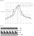
- FIG. 4 Measured values according to Example 1 and Comparative Examples 1 to 3 are illustrated in FIG. 4 .
- the horizontal axis indicates the viewing angles
- the vertical axis indicates brightness (nit).
- Example 1 may obtain a wider viewing angle than Comparative Examples 1 and 3, a maximum brightness value is made in a direction of about -5° based on the front side, and as a result, it is possible to obtain a clear image within a driver's visual field when the viewing angle compensation film is applied to a display for a vehicle.
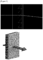
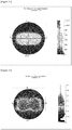
- FIGS. 11 to 13 A distribution of viewing angles in on/off states of a panel (white/black modes) was measured and the C/R was calculated by using EZContrast x188 Equipment of Eldim, and a result thereof is shown in Table 1.
- experimental results of Example 2 are illustrated in FIGS. 11 to 13 , and 18
- experimental results of Comparative Example 4 are illustrated in FIGS. 14 to 17 .
- the following FIGS. 11 and 14 are views illustrating measured white brightness (luminance white, Lw)
- FIGS. 12 and 15 are views illustrating measured black brightness (luminance black, Lb)
- FIGS. 13 and 16 are views illustrating Lw/Lb.
- FIG. 17 is a view illustrating a CR curve according to Comparative Example 4, and FIG.
- Example 18 is a view illustrating a CR curve according to Example 2.
- Example 2 Front CR 1568 1667 Area A ⁇ CR Upper Right/Upper Left/Lower Right/Lower Left 673/580/1092/1032 871/911/977/994 Area A CR Upper Right/Upper Left/Lower Right/Lower Left 739/646/1120/1006 336/355/1296/1199
Landscapes
- Physics & Mathematics (AREA)
- Nonlinear Science (AREA)
- Optics & Photonics (AREA)
- General Physics & Mathematics (AREA)
- Crystallography & Structural Chemistry (AREA)
- Chemical & Material Sciences (AREA)
- Mathematical Physics (AREA)
- Engineering & Computer Science (AREA)
- Health & Medical Sciences (AREA)
- Manufacturing & Machinery (AREA)
- Ophthalmology & Optometry (AREA)
- Mechanical Engineering (AREA)
- Polarising Elements (AREA)
- Liquid Crystal (AREA)
- Optical Elements Other Than Lenses (AREA)
Applications Claiming Priority (2)
| Application Number | Priority Date | Filing Date | Title |
|---|---|---|---|
| KR20180024548 | 2018-02-28 | ||
| PCT/KR2019/002374 WO2019168345A1 (ko) | 2018-02-28 | 2019-02-27 | 시야각 보상필름, 이를 포함하는 편광판 및 이를 포함하는 디스플레이 장치 |
Publications (2)
| Publication Number | Publication Date |
|---|---|
| EP3761073A1 true EP3761073A1 (de) | 2021-01-06 |
| EP3761073A4 EP3761073A4 (de) | 2021-04-21 |
Family
ID=67805437
Family Applications (1)
| Application Number | Title | Priority Date | Filing Date |
|---|---|---|---|
| EP19761636.0A Withdrawn EP3761073A4 (de) | 2018-02-28 | 2019-02-27 | Betrachtungswinkelkompensationsfilm, polarisationsplatte damit und anzeigevorrichtung damit |
Country Status (7)
| Country | Link |
|---|---|
| US (1) | US11686967B2 (de) |
| EP (1) | EP3761073A4 (de) |
| JP (1) | JP6929590B2 (de) |
| KR (1) | KR102364573B1 (de) |
| CN (1) | CN111164465B (de) |
| TW (1) | TWI696872B (de) |
| WO (1) | WO2019168345A1 (de) |
Cited By (1)
| Publication number | Priority date | Publication date | Assignee | Title |
|---|---|---|---|---|
| EP3832361A4 (de) * | 2018-07-27 | 2021-09-29 | Lg Chem, Ltd. | Verfahren zur herstellung einer betrachtungswinkelkompensationsfolie, verfahren zur herstellung einer polarisationsplatte, betrachtungswinkelkompensationsfolie, polarisationsplatte und anzeigevorrichtung damit |
Families Citing this family (3)
| Publication number | Priority date | Publication date | Assignee | Title |
|---|---|---|---|---|
| KR102690397B1 (ko) | 2019-10-31 | 2024-08-02 | 삼성디스플레이 주식회사 | 광학 필름 및 이를 포함하는 표시 장치 |
| US12339441B2 (en) * | 2021-05-12 | 2025-06-24 | Cm Visual Technology Corporation | Optical film |
| CN115508926B (zh) * | 2022-08-17 | 2025-01-28 | 惠州华星光电显示有限公司 | 一种视角扩大膜及其制备方法、显示装置 |
Family Cites Families (43)
| Publication number | Priority date | Publication date | Assignee | Title |
|---|---|---|---|---|
| JPH0627325A (ja) * | 1992-07-07 | 1994-02-04 | Sekisui Chem Co Ltd | 面光源装置 |
| JP2001174815A (ja) | 1999-12-20 | 2001-06-29 | Nitto Denko Corp | 液晶表示装置 |
| KR100784806B1 (ko) * | 2001-09-04 | 2007-12-14 | 삼성전자주식회사 | 광 특성 보상 필름, 이의 제조 방법, 및 광 특성 보상 필름을 포함하는 시야각이 변경된 표시장치 |
| KR100806165B1 (ko) * | 2001-09-12 | 2008-02-22 | 삼성전자주식회사 | 액정표시장치 |
| JP2003177394A (ja) * | 2001-12-12 | 2003-06-27 | Casio Comput Co Ltd | 反射偏光素子及びそれを用いた液晶表示装置 |
| WO2005017581A2 (en) * | 2003-08-15 | 2005-02-24 | Koninklijke Philips Electronics N.V. | Backlight device |
| WO2006088930A2 (en) * | 2005-02-17 | 2006-08-24 | 3M Innovative Properties Company | Brightness enhancement film comprising polymerized organic phase having low glass transition temperature |
| KR101255296B1 (ko) | 2005-06-29 | 2013-04-15 | 엘지디스플레이 주식회사 | 프리즘 시트와 이를 이용한 백 라이트 유닛 |
| WO2007139209A1 (en) * | 2006-05-31 | 2007-12-06 | Semiconductor Energy Laboratory Co., Ltd. | Display device and electronic device |
| KR101266352B1 (ko) * | 2006-06-30 | 2013-05-22 | 엘지디스플레이 주식회사 | 액정표시장치 |
| KR100786384B1 (ko) * | 2006-10-25 | 2007-12-14 | 미래나노텍(주) | 광학 시트 및 상기 광학 시트가 구비된 액정표시장치의백라이트 어셈블리 |
| CN101196586A (zh) * | 2006-12-05 | 2008-06-11 | 迎辉科技股份有限公司 | 具有扩散粒子的复合式聚光片 |
| JP4321612B2 (ja) * | 2007-03-19 | 2009-08-26 | ソニー株式会社 | 光学シート組合せ体、面発光装置および液晶表示装置 |
| JP2008256998A (ja) * | 2007-04-06 | 2008-10-23 | Nitto Denko Corp | 積層光学フィルム、積層光学フィルムを用いた液晶パネル、および液晶表示装置 |
| CN101680628A (zh) * | 2007-05-09 | 2010-03-24 | 皇家飞利浦电子股份有限公司 | 光源覆盖物 |
| JP4384214B2 (ja) * | 2007-09-27 | 2009-12-16 | 株式会社 日立ディスプレイズ | 面発光素子,画像表示素子及びそれを用いた画像表示装置 |
| JP2009109969A (ja) * | 2007-10-12 | 2009-05-21 | Hitachi Chem Co Ltd | プリズムシ−ト、光学部材及びそれを用いた面状光源装置 |
| KR101210985B1 (ko) | 2008-12-26 | 2012-12-11 | 주식회사 엘지화학 | 모아레가 개선된 렌티큘러 광학 필름 및 이를 포함하는 백라이트 유닛 |
| WO2011013401A1 (ja) * | 2009-07-28 | 2011-02-03 | シャープ株式会社 | 光学フィルム、その製造方法及びその光学特性を制御する方法 |
| JP2012033276A (ja) * | 2010-07-28 | 2012-02-16 | Minebea Co Ltd | 面状照明装置 |
| US8804067B2 (en) * | 2011-05-02 | 2014-08-12 | Au Optronics Corporation | Display device |
| KR101421025B1 (ko) * | 2011-05-16 | 2014-07-22 | 코닝정밀소재 주식회사 | 컬러 시프트 및 시인성이 향상된 유기 발광 표시장치 |
| KR101314486B1 (ko) * | 2011-07-06 | 2013-10-07 | (주)이노웍스 | 디스플레이 소자 위에 형성되는 시야각 제어 시트 |
| JP2013047794A (ja) * | 2011-07-28 | 2013-03-07 | Fujifilm Corp | 液晶表示装置 |
| CN102305956A (zh) * | 2011-08-30 | 2012-01-04 | 明基材料有限公司 | 光学补偿膜及其制造方法 |
| US9004726B2 (en) * | 2011-10-27 | 2015-04-14 | Svv Technology Innovations, Inc. | Light directing films |
| US9209230B2 (en) | 2012-12-21 | 2015-12-08 | Samsung Electronics Co., Ltd | Optical films for reducing color shift and organic light-emitting display apparatuses employing the same |
| KR102107563B1 (ko) * | 2013-08-08 | 2020-05-08 | 삼성디스플레이 주식회사 | 광학 필름, 이를 포함하는 표시 장치 및 광학 필름의 제조 방법 |
| CN103901514A (zh) * | 2014-03-21 | 2014-07-02 | 京东方科技集团股份有限公司 | 一种光学棱镜、棱镜片、背光模组和液晶显示装置 |
| JP6060106B2 (ja) * | 2014-04-09 | 2017-01-11 | 富士フイルム株式会社 | 輝度向上膜、偏光板、および画像表示装置 |
| CN104391346A (zh) * | 2014-07-22 | 2015-03-04 | 翰博高新材料(合肥)股份有限公司 | 一种视角偏转结构棱镜膜 |
| KR101822699B1 (ko) | 2014-12-23 | 2018-01-30 | 삼성에스디아이 주식회사 | 광학시트 및 이를 포함하는 액정표시장치 |
| CN107111037B (zh) * | 2014-12-23 | 2019-10-25 | 三星Sdi株式会社 | 光学片以及包括其的偏光板和液晶显示器 |
| US10007139B2 (en) * | 2014-12-31 | 2018-06-26 | Samsung Sdi Co., Ltd. | Liquid crystal display module and liquid crystal display comprising the same |
| JP6159385B2 (ja) * | 2014-12-31 | 2017-07-05 | 三星エスディアイ株式会社SAMSUNG SDI Co., LTD. | 液晶表示装置用モジュール及びこれを含む液晶表示装置 |
| KR101640718B1 (ko) | 2014-12-31 | 2016-07-18 | 삼성에스디아이 주식회사 | 액정표시장치용 모듈 및 이를 포함하는 액정표시장치 |
| KR101665239B1 (ko) * | 2015-02-27 | 2016-10-12 | 삼성에스디아이 주식회사 | 편광판 및 이를 포함하는 액정표시장치 |
| JP7152129B2 (ja) * | 2015-02-27 | 2022-10-12 | 三星エスディアイ株式会社 | 偏光板及びこれを含む液晶表示装置 |
| CN105068298B (zh) * | 2015-06-23 | 2018-01-12 | 深圳市华星光电技术有限公司 | 视角扩大膜及包括其的广视角薄膜晶体管液晶显示装置 |
| KR101665263B1 (ko) * | 2015-10-01 | 2016-10-11 | 삼성에스디아이 주식회사 | 편광판 및 이를 포함하는 액정표시장치 |
| KR102006267B1 (ko) * | 2016-06-30 | 2019-10-02 | 엘지디스플레이 주식회사 | 광학식 이미지 인식 센서 내장형 평판 표시장치 |
| KR101861143B1 (ko) | 2016-08-30 | 2018-05-28 | 연세대학교 산학협력단 | 교정 절골술용 각도기 |
| CN107741611A (zh) * | 2017-11-10 | 2018-02-27 | 凯鑫森(上海)功能性薄膜产业有限公司 | 棱镜片及背光模组 |
-
2019
- 2019-02-27 KR KR1020190023304A patent/KR102364573B1/ko active Active
- 2019-02-27 TW TW108106930A patent/TWI696872B/zh active
- 2019-02-27 US US16/757,741 patent/US11686967B2/en active Active
- 2019-02-27 CN CN201980004811.XA patent/CN111164465B/zh active Active
- 2019-02-27 JP JP2020519770A patent/JP6929590B2/ja active Active
- 2019-02-27 EP EP19761636.0A patent/EP3761073A4/de not_active Withdrawn
- 2019-02-27 WO PCT/KR2019/002374 patent/WO2019168345A1/ko not_active Ceased
Cited By (2)
| Publication number | Priority date | Publication date | Assignee | Title |
|---|---|---|---|---|
| EP3832361A4 (de) * | 2018-07-27 | 2021-09-29 | Lg Chem, Ltd. | Verfahren zur herstellung einer betrachtungswinkelkompensationsfolie, verfahren zur herstellung einer polarisationsplatte, betrachtungswinkelkompensationsfolie, polarisationsplatte und anzeigevorrichtung damit |
| US12124066B2 (en) | 2018-07-27 | 2024-10-22 | Lg Chem, Ltd. | Method for manufacturing viewing angle compensation film, method for manufacturing polarizing plate, viewing angle compensation film, polarizing plate, and display device including same |
Also Published As
| Publication number | Publication date |
|---|---|
| KR20190103980A (ko) | 2019-09-05 |
| WO2019168345A1 (ko) | 2019-09-06 |
| CN111164465A (zh) | 2020-05-15 |
| US20210191186A1 (en) | 2021-06-24 |
| EP3761073A4 (de) | 2021-04-21 |
| JP6929590B2 (ja) | 2021-09-01 |
| US11686967B2 (en) | 2023-06-27 |
| TW201945811A (zh) | 2019-12-01 |
| CN111164465B (zh) | 2022-07-12 |
| TWI696872B (zh) | 2020-06-21 |
| KR102364573B1 (ko) | 2022-02-18 |
| JP2020536289A (ja) | 2020-12-10 |
Similar Documents
| Publication | Publication Date | Title |
|---|---|---|
| US11686967B2 (en) | Viewing angle compensation film, polarizing plate comprising same, and display device comprising same | |
| KR102418663B1 (ko) | 시야각 보상필름, 이를 포함하는 편광판 및 이를 포함하는 디스플레이 장치 | |
| US11550184B2 (en) | Polarizing plate laminate and display device comprising same | |
| KR102740134B1 (ko) | 시야각 보상필름 및 이를 포함하는 편광판 | |
| KR102740129B1 (ko) | 시야각 보상필름 및 이를 포함하는 편광판 | |
| KR102762133B1 (ko) | 편광판 적층체 및 이를 포함하는 디스플레이 장치 | |
| KR102283126B1 (ko) | 시야각 보상필름의 제조방법, 편광판의 제조방법, 시야각 보상 필름, 편광판 및 이를 포함하는 디스플레이 장치 | |
| KR102716885B1 (ko) | 시야각 보상필름, 이를 포함하는 편광판 및 이를 포함하는 디스플레이 장치 | |
| KR102530187B1 (ko) | 편광판 적층체 및 이를 포함하는 디스플레이 장치 | |
| KR102530188B1 (ko) | 편광판 적층체 및 이를 포함하는 디스플레이 장치 | |
| KR20210024799A (ko) | 시야각 보상필름 및 이를 포함하는 편광판 | |
| KR20200059613A (ko) | 액정표시장치 및 액정표시장치의 제조방법 |
Legal Events
| Date | Code | Title | Description |
|---|---|---|---|
| STAA | Information on the status of an ep patent application or granted ep patent |
Free format text: STATUS: THE INTERNATIONAL PUBLICATION HAS BEEN MADE |
|
| PUAI | Public reference made under article 153(3) epc to a published international application that has entered the european phase |
Free format text: ORIGINAL CODE: 0009012 |
|
| STAA | Information on the status of an ep patent application or granted ep patent |
Free format text: STATUS: REQUEST FOR EXAMINATION WAS MADE |
|
| 17P | Request for examination filed |
Effective date: 20200323 |
|
| AK | Designated contracting states |
Kind code of ref document: A1 Designated state(s): AL AT BE BG CH CY CZ DE DK EE ES FI FR GB GR HR HU IE IS IT LI LT LU LV MC MK MT NL NO PL PT RO RS SE SI SK SM TR |
|
| AX | Request for extension of the european patent |
Extension state: BA ME |
|
| A4 | Supplementary search report drawn up and despatched |
Effective date: 20210324 |
|
| RIC1 | Information provided on ipc code assigned before grant |
Ipc: G02B 5/04 20060101AFI20210318BHEP Ipc: G02B 5/30 20060101ALI20210318BHEP Ipc: G02F 1/1335 20060101ALI20210318BHEP |
|
| DAV | Request for validation of the european patent (deleted) | ||
| DAX | Request for extension of the european patent (deleted) | ||
| STAA | Information on the status of an ep patent application or granted ep patent |
Free format text: STATUS: EXAMINATION IS IN PROGRESS |
|
| 17Q | First examination report despatched |
Effective date: 20230504 |
|
| STAA | Information on the status of an ep patent application or granted ep patent |
Free format text: STATUS: THE APPLICATION IS DEEMED TO BE WITHDRAWN |
|
| 18D | Application deemed to be withdrawn |
Effective date: 20250812 |