EP3761123B1 - Composant de micromécanique permettant le confinement d'une substance lubrifiante - Google Patents
Composant de micromécanique permettant le confinement d'une substance lubrifiante Download PDFInfo
- Publication number
- EP3761123B1 EP3761123B1 EP19184822.5A EP19184822A EP3761123B1 EP 3761123 B1 EP3761123 B1 EP 3761123B1 EP 19184822 A EP19184822 A EP 19184822A EP 3761123 B1 EP3761123 B1 EP 3761123B1
- Authority
- EP
- European Patent Office
- Prior art keywords
- microstructured
- zone
- component according
- microcavities
- micro
- Prior art date
- Legal status (The legal status is an assumption and is not a legal conclusion. Google has not performed a legal analysis and makes no representation as to the accuracy of the status listed.)
- Active
Links
Images


Classifications
-
- G—PHYSICS
- G04—HOROLOGY
- G04B—MECHANICALLY-DRIVEN CLOCKS OR WATCHES; MECHANICAL PARTS OF CLOCKS OR WATCHES IN GENERAL; TIME PIECES USING THE POSITION OF THE SUN, MOON OR STARS
- G04B31/00—Bearings; Point suspensions or counter-point suspensions; Pivot bearings; Single parts therefor
- G04B31/08—Lubrication
-
- G—PHYSICS
- G04—HOROLOGY
- G04B—MECHANICALLY-DRIVEN CLOCKS OR WATCHES; MECHANICAL PARTS OF CLOCKS OR WATCHES IN GENERAL; TIME PIECES USING THE POSITION OF THE SUN, MOON OR STARS
- G04B13/00—Gearwork
- G04B13/02—Wheels; Pinions; Spindles; Pivots
-
- G—PHYSICS
- G04—HOROLOGY
- G04B—MECHANICALLY-DRIVEN CLOCKS OR WATCHES; MECHANICAL PARTS OF CLOCKS OR WATCHES IN GENERAL; TIME PIECES USING THE POSITION OF THE SUN, MOON OR STARS
- G04B15/00—Escapements
- G04B15/14—Component parts or constructional details, e.g. construction of the lever or the escape wheel
-
- G—PHYSICS
- G04—HOROLOGY
- G04B—MECHANICALLY-DRIVEN CLOCKS OR WATCHES; MECHANICAL PARTS OF CLOCKS OR WATCHES IN GENERAL; TIME PIECES USING THE POSITION OF THE SUN, MOON OR STARS
- G04B31/00—Bearings; Point suspensions or counter-point suspensions; Pivot bearings; Single parts therefor
- G04B31/004—Bearings; Point suspensions or counter-point suspensions; Pivot bearings; Single parts therefor characterised by the material used
- G04B31/008—Jewel bearings
Definitions
- the present invention relates to a micromechanical component intended for watch mechanisms, in particular a component which requires lubrication.
- this lubricant may escape from the area where it has been deposited.
- the movement of the parts tends to move the lubricant from the contact area to an area not subject to friction.
- a small mechanical component such as a timepiece component, it is difficult to form a lubricating film only at a specific region.
- the ability of the mechanical component to retain the lubricant durably after a surface treatment and/or the addition of a film of controlled chemical nature can be improved, with the aim of reducing the wear suffered by the mechanical component due to an insufficiency of lubricating oil.
- the document CH713426 describes a first mechanical component having a first surface area, a second component having a second surface area on which the first surface area can slide.
- An oil retaining film is formed on at least one receiving area selected from the first and second surface areas, the oil retaining film being more oleophilic than the receiving area.
- the oil retaining film is a chemical compound comprising one of the elements Si, Ti, and Zr and a hydrocarbon radical.
- the document EP3002637 describes a watch system comprising a first component with at least a first functional zone coming into frictional contact with at least a second functional zone of a second component during operation of the watch system; in this component, at least one of the first functional zone and the second functional zone comprises a controlled submicron structuring.
- the present disclosure relates to a micromechanical component intended for watch mechanisms, at least part of the component being made of a crystalline mineral material based on carbon or alumina comprising at least one contact surface. intended to come into sliding and/or pivoting contact; the contact surface locally comprises at least a first microstructured zone having a three-dimensional texture; the three-dimensional texture being formed of microcavities, making the first microstructured zone more oleophobic than the non-microstructured contact surface; the first microstructured zone is configured to locally confine a lubricating substance on a lubricated portion of the contact surface.
- the first microstructured zone extends to the periphery of the lubricated portion.
- the component described herein improves the confinement of the lubricating substance in a portion of the contact surface.
- different arrangements of oleophilic and oleophobic areas can be provided near or on the contact surface.
- the microstructured area thus allows the spatial localization of the lubricating substance in a portion of the contact surface to be controlled according to different lubrication applications.
- the component described herein can also improve the supply of the lubricating substance to the portion of the contact surface.
- FIG. 1 schematically represents a micromechanical component 10 intended for clock mechanisms, according to an embodiment of the invention as claimed.
- the component 10 comprising at least one contact surface 100, at least a portion of the contact surface 100 being intended to come into sliding and/or pivoting contact, for example with another component of a clockwork mechanism.
- the component 10 is manufactured entirely or partly made of a crystalline mineral material based on carbon or alumina (Al 2 O 3 ).
- the crystalline mineral material is ruby, sapphire or diamond, natural or synthetic.
- Other materials are also conceivable, such as polymers, metals or metal alloys, ceramics, silica, glass, silicon, etc.
- the component 10, manufactured entirely or partly made of a crystalline mineral material, comprises a contact surface 100 locally comprising at least one microstructured zone 110.
- the microstructured zone 110 can be made more oleophobic than the non-microstructured contact surface 100.
- the microstructured zone 110 can be made more oleophilic than the non-microstructured contact surface 100.
- the microstructured area 110 has a three-dimensional texture formed of microcavities 20.
- the microcavities 20 typically have an essentially truncated cone shape narrowing towards the bottom of the cavity 20.
- the lateral dimension L of the microcavity 20 at the surface is between 5 ⁇ m and 150 ⁇ m and preferably between 10 ⁇ m and 60 ⁇ m.
- the ratio of the height H to the lateral dimension L of the microcavity 20 is between 0.01 and 1.
- the microcavities 20 are non-communicating, that is to say that the cavities 20 do not communicate fluidically with each other.
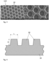
- FIG. 3 shows a micrograph (for two magnifications) of a three-dimensional texture comprising 20 microcavities formed in a single-crystal pellet of traditional watch ruby (Verneuil ruby Al 2 O 3 Cr, cleaved, cut and polished).
- the microcavities have a lateral dimension L of approximately 25 ⁇ m.
- the microstructured area 110 also has a three-dimensional texture formed of micro-pillars 30.
- the micro-pillars 30 typically have an essentially truncated cone shape tapering towards the top of the micro-pillar 30.
- the lateral dimension L of the micro-pillar 30 at its base is between 5 ⁇ m and 150 ⁇ m and preferably between 10 ⁇ m and 60 ⁇ m.
- the ratio of the height H to the lateral dimension L of the micro-pillar 30 is between 0.01 and 1.
- the lateral dimension L of the microcavities 20 and the micro-pillars 30 between 10 ⁇ m and 60 ⁇ m is more favorable for watchmaking applications, given the dimensions of the watchmaking components coming into contact.
- FIG. 5 shows an SEM micrograph (for two magnifications) of a three-dimensional texture comprising 20 micro-pillars formed in the same single-crystal ruby pellet as in fig. 3 .
- the micro-pillars 30 have a lateral dimension L of approximately 25 ⁇ m.
- the microstructured area 110 comprises a corrugation microstructure 40.
- the fig. 6 shows an SEM micrograph of the 40 ripple microstructure formed in the same ruby single crystal pellet as in fig. 3 .
- the ripple microstructure 40 typically has a double texture consisting of parallel grooves with a typical width of between 7 and 12 ⁇ m and a depth of less than 1 ⁇ m (typically 0.2 to 0.9 ⁇ m). Along a groove, the depth is modulated by an oscillation with a micrometric period (typically 1 ⁇ m) and an amplitude of less than 0.2 ⁇ m.
- the microstructured zone 110 comprises the texture formed of micro-pillars 30 on which the undulation microstructure 40 is superimposed.
- fig. 7 shows an SEM micrograph of such a texture made in the same single-crystal ruby pellet as in fig. 3 .
- microcavities 20 and micropillars 30 may be arranged in a regular pattern, for example hexagonal or square, or in an irregular pattern.
- the density of the microcavities 20 or micropillars 30 in the microstructured area 110 may be between 0.1 and 0.9, and preferably between 0.4 and 0.8.
- the textures comprising the ripple microstructure, the microcavities 20, the micropillars 30 and the 30 micro-pillars with the superimposed ripple microstructure, were made using a femtosecond laser.
- a femtosecond laser e.g., a laser that is a laser that is a laser that is a laser that is a laser that is a laser that is a laser that is a laser that is a laser that is a femtosecond laser.
- other methods of manufacturing textures are possible, such as microfabrication, mechanical machining, diamond wire or others.
- the wettability and the more or less oleophilic or oleophobic nature of the contact surface 100 with respect to a liquid were evaluated by measuring the contact angle on dynamic shots during the advancement ( ⁇ CA ) of a drop of liquid injected continuously by a micro-cannula above the contact surface 100 in the absence of the microstructured zone 110 and above the contact surface 100 comprising the microstructured zone 110, for example as shown in FIG. fig. 8 (unclaimed configuration).
- the measurement of the contact angle ⁇ CA was carried out with the watch oil Synth-A-lube 9010 manufactured by the Moebius division of The Swatch Group Research and Development Ltd.
- the crystalline mineral material is ruby.
- the contact angle measurements were performed on the contact surface 100 in the natural state (without preparation), as well as after chemical treatment consisting in this embodiment of a combination of solvent cleaning followed by oxygen plasma treatment.
- This preparation makes it possible to reduce the carbon contamination of the surface to a threshold below 10% at.
- the contact angles are less than 30°.
- the contact angle measurements were carried out on the contact surface 100 having undergone the above preparation, followed by an epilaming treatment.
- the contact surface 100 is covered with a very thin film of fluoropolymer.
- the epilaming treatment is carried out with the standard watchmaking product Fixodrop ® from Moebius.
- Table 1 reports the contact angles ⁇ CA measured on the non-microstructured contact surface 100 and on the contact surface 100 comprising a microstructured zone 110 having a texture formed of microcavities 20, formed of micro-pillars 30 and formed only of the corrugation microstructure.
- the contact angles ⁇ CA were also measured on the contact surface 100 having a texture formed of micro-pillars 30 on which the corrugation microstructure is superimposed.
- the measurements were performed on textures having the following dimensions: 20 microcavities with a lateral dimension L of 25.6 ⁇ 0.6 ⁇ m and a depth of 13.8 ⁇ 0.2 ⁇ m, 30 micropillars with a lateral dimension L of 15 ⁇ 1 ⁇ m and a height of 8 to 9 ⁇ m, and a ripple microstructure with a valley-to-peak height of 6 ⁇ 0.5 ⁇ m and a spacing between the peaks of 0.2 to 0.9 ⁇ m.
- the 20 microcavities are arranged in a hexagonal pattern and the micropillars are arranged in a square pattern.
- the ripple microstructure is arranged in bands of 10 ⁇ m periodicity.
- Table 1 Texture Surface condition ⁇ CA non-microstructured plasma 29 hair removal 57 microcavities plasma 62 hair removal 125 micro-pillars plasma 21 micro-pillars with ripple microstructure plasma 19 ripple microstructure plasma 30
- Table 1 shows that the texture formed by microcavities 20 makes it possible to obtain a contact angle ⁇ CA during advancement of approximately 62°, significantly higher than that measured on the contact surface 100.
- non-microstructured ⁇ CA zt 29°.
- the contact angle ⁇ CA measured during advancement for the texture formed of microcavities 20 is similar to that measured ( ⁇ CA zt 57°) for the non-microstructured contact surface 100 comprising an epilame film (epilamage).
- the texture formed of microcavities 20 comprising the epilame film makes it possible to obtain a contact angle ⁇ CA of approximately 125°, i.e. double that measured in the absence of the epilame film.
- the oleophobic nature of the texture formed of microcavities 20 comprising the epilame film is particularly remarkable.
- the oil droplet exhibits pinning effects and as soon as the oil droplet leaves the textured surface, it tends to roll and attach to the non-microstructured surface adjacent to the microstructured zone 110.
- the texture formed of micro-pillars 30 results in a contact angle ⁇ CA of approximately 21°, therefore significantly lower than those obtained for the texture formed of microcavities 20.
- the texture formed of micro-pillars 30 comprising the superimposed corrugation microstructure results in a contact angle ⁇ CA of approximately 19°, also significantly lower than those obtained for the texture formed of microcavities 20.
- the texture formed of micro-pillars 30 with or without superimposed corrugation microstructure is more oleophilic than the non-microstructured contact surface 100.
- a contact angle ⁇ CA of approximately 30° is measured.
- the corrugation microstructure has very little influence on the contact angle and therefore the oleophilic/oleophobic character of the contact surface 100.
- the microstructured area 110 therefore makes it possible to influence the wettability of a watch oil.
- the texture formed of micro-pillars 30 makes it possible to make the surface more oleophilic than the non-microstructured contact surface 100 and the texture formed of microcavities 20 makes the surface more oleophobic than the non-microstructured 100 contact surface.
- the microstructured area 110 comprises a film of a substance for modifying the surface energy.
- the film may comprise a film of nanometric thickness, comprising a fluorinated active agent.
- the film may comprise an epilame film. The addition of such a film to the microstructured area 110 comprising the texture formed of microcavities 20 makes it possible to further increase by cumulative effect the oleophobic nature of the microstructured area 110.
- the contact surface 100 comprising the microstructured area 110 may receive an oxygen plasma treatment, possibly after solvent cleaning.
- an oxygen plasma treatment increases the oleophobic nature of the microstructured area 110 comprising the texture formed of microcavities 20 and increases the oleophilic nature of the microstructured area 110 comprising the texture formed of micro-pillars 30.
- microcavities 20 or micropillars 30 having a lateral dimension L of between 5 ⁇ m and 150 ⁇ m, as well as to microcavities 20 or micropillars 30 whose ratio of the height H to the lateral dimension L of the microcavity 20 is between 0.01 and 1.
- microcavities 20 or micropillars 30 in the microstructured zone 110 comprising microcavities 20 or micropillars 30, between 0.1 and 0.9.
- the contact surface 100 comprises a lubricated portion 120, that is to say a portion of the contact surface 100 intended to receive a lubricating substance (for example a watch oil or the like).
- the lubricated portion 120 may correspond to said at least one portion of the contact surface 100 intended to come into sliding and/or pivoting contact.
- the microstructured zone 110 extends to the periphery of the lubricated portion 120. In the case where the microstructured zone 110 is more oleophobic than the lubricated portion 120, the microstructured zone 110 will confine the lubricating substance in the lubricated portion 120.
- the microstructured zone 110 may comprise the texture formed of microcavities 20.
- the lubricated portion 120 of the contact surface 100 is non-microstructured and therefore more oleophilic than the microstructured zone 110.
- the microstructured area 110 extends into the lubricated portion 120 and the remainder of the contact surface 100 is non-microstructured.
- the microstructured area 110 is made more oleophilic than the remainder of the contact surface 100 by comprising the texture formed by micro-pillars 30, or possibly micro-pillars 30 comprising the superimposed corrugation microstructure.
- the contact surface 100 comprises a first microstructured zone 111 extending at the periphery of the lubricated portion 120 and a second microstructured zone 112 extending into the lubricated portion 120.
- the first microstructured zone 111 is preferably more oleophobic than the second microstructured zone 112 so as to confine the lubricating substance in the lubricated portion 120.
- the first microstructured zone 111 may have a texture formed of microcavities 20 and the second microstructured zone 112 may have a texture formed of micro-pillars 30.
- An advantage of this configuration is that the oleophilic nature of the second microstructured zone 112 already retains the lubricating substance in the lubricated portion 120, this confinement being reinforced by the first oleophobic microstructured zone 111 at the periphery of the lubricated portion 120.
- the microstructured zone 110 which may comprise the first microstructured zone 111, may extend over the entire remainder of the contact surface 100, i.e. the entire contact surface 100 outside the lubricated portion 120.
- microstructured area 110 including the first and second microstructured areas 111, 112 are also possible such that the microstructured area 110 extends over a portion of the contact surface 100 or over the entire contact surface 100.
- the cavities 20 of the texture formed by microcavities 20 can also serve as reservoirs for the lubricating substance.
- the lubricating substance can then become trapped in the microcavities 20.
- the microcavities 20 ensure the supply of lubricant to the contact surface 100.
- microstructured area 110 on the contact surface 100 are also possible so as to obtain more or less oleophobic and/or oleophilic arrangements of areas on the contact surface 100.
- the different spatial combinations of the microstructured area 110 can be combined with a film of a substance for modifying the surface energy and/or an oxygen plasma treatment in order to modify the oleophobic and/or oleophilic character of the microstructured area 110. It is thus possible to optimize the confinement of the lubricating substance near and/or in the lubricated portion 120 in order to guarantee a lasting localization of the lubricant in this area.
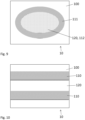
- FIG. 10 schematically represents the component according to another embodiment, in which the contact surface 100 comprises two microstructured zones 110 in a strip limiting the lubricated portion 120 between the two microstructured zones 110.
- Such an arrangement can be advantageous in the case of linear contact (in the direction of the bands of the microstructured zone 110).
- the microstructured zone 110 may be included on a watch component 10, in particular a watch component that slides and pivots, for example against another fixed or moving watch component.
- the microstructured area 110 may be included on a pivot or bearing stone, an escapement pallet, a chainring pin, a tooth, or other functional or decorative parts.
Landscapes
- Physics & Mathematics (AREA)
- General Physics & Mathematics (AREA)
- Micromachines (AREA)
- Sliding-Contact Bearings (AREA)
- Lubricants (AREA)
Description
- La présente invention concerne un composant de micromécanique destiné aux mécanismes d'horlogerie, notamment un composant amené à être lubrifié.
- Il est connu que dans les mécanismes d'horlogerie, nombreuses sont les pièces en mouvement et en contact avec frottement les unes avec les autres. Ces frottements doivent être réduits le plus possible car ils peuvent affecter la précision et/ou l'autonomie du mécanisme. Pour réduire ces frottements il est donc connu d'utiliser un lubrifiant liquide ou visqueux. Ce lubrifiant est utilisé parcimonieusement sur des zones bien définies et en quantités adaptées.
- Cependant, ce lubrifiant peut s'échapper de la zone où il a été déposé. En particulier, dans l'état chimique naturel des surfaces résultant de l'exposition aux conditions ambiantes, le mouvement des pièces tend à déplacer le lubrifiant de la zone de contact vers une zone non soumise à frottement. De plus, sur un composant mécanique de petite taille tel qu'un composant de pièce d'horlogerie, il est difficile de former un film lubrifiant seulement au niveau d'une région spécifique.
- Afin que la partie prévue pour glisser retienne le lubrifiant pour que soit réduite l'usure due à la friction causée par le glissement durant une rotation ou analogue, il est usuel de traiter chimiquement la surface. L'état chimique de la surface est obtenu par différents types de nettoyages, suivis éventuellement du revêtement de la pièce par un film d'épaisseur nanométrique, comprenant un agent actif fluoré. Différents agents actifs fluorés sont connus dans le secteur horloger sous la dénomination d'épilame. Le revêtement des composants avec ce type de produit, hors zone de contact, permet de retenir le lubrifiant dans la zone de contact grâce à la réduction de l'énergie de surface de la pièce traitée.
- Cependant, la capacité du composant mécanique à retenir durablement le lubrifiant après un traitement de surface et/ou l'adjonction d'un film de nature chimique contrôlé peut être améliorée, avec l'objectif de réduire l'usure subie par le composant mécanique du fait d'une insuffisance d'huile lubrifiante.
- Le document
CH713426 - Le document
EP3002637 décrit un système horloger comprenant un premier composant avec au moins une première zone fonctionnelle venant en contact de frottement avec au moins une seconde zone fonctionnelle d'un deuxième composant lors du fonctionnement du système horloger; dans ce composant, au moins l'une de la première zone fonctionnelle et de la seconde zone fonctionnelle comporte une structuration submicronique contrôlée. - La présente divulgation concerne un composant de micromécanique destiné aux mécanismes d'horlogerie, au moins une partie du composant étant constituée dans un matériau minéral cristallin à base de carbone ou d'alumine comprenant au moins une surface de contact destinée à venir en contact en glissement et/ou en pivotement; la surface de contact comprend localement au moins une première zone microstructurée présentant une texture tridimensionnelle; la texture tridimensionnelle étant formée de microcavités, rendant la première zone microstructurée plus oléophobe que la surface de contact non microstructurée; la première zone microstructurée est configurée pour confiner localement une substance lubrifiante sur une portion lubrifiée de la surface de contact. La première zone microstructurée s'étend à la périphérie de la portion lubrifiée.
- Le composant décrit ici améliore le confinement de la substance lubrifiante dans une portion de la surface de contact. Selon la configuration de la zone microstructurée, différents arrangements de zones oléophiles et oléophobes peuvent être pourvus à proximité ou sur la surface de contact. La zone microstructurée permet donc de maîtriser la localisation spatiale de la substance lubrifiante dans une portion de la surface de contact selon les différentes applications de lubrification. Le composant décrit ici peut également améliorer l'approvisionnement de la substance lubrifiante dans la portion de la surface de contact.
- Des exemples de mise en oeuvre de l'invention sont indiqués dans la description illustrée par les figures annexées dans lesquelles :
- la
figure 1 représente schématiquement un composant de micromécanique comportant une surface de contact ayant une zone microstructurée, selon un mode de réalisation; - la
figure 2 illustre la zone microstructurée présentant une texture tridimensionnelle formée de microcavités, selon un mode de réalisation; - la
figure 3 montre une micrographie MEB de la texture comprenant des microcavités; - la
figure 4 illustre la zone microstructurée présentant une texture tridimensionnelle formée de micro-piliers, selon un mode de réalisation; - la
figure 5 montre une micrographie MEB de la texture comprenant des micro-piliers; - la
figure 6 montre micrographie MEB d'une microstructure d'ondulation, selon un mode de réalisation; - la
figure 7 montre une micrographie MEB d'une texture formée de micro-piliers sur laquelle est superposée la microstructure d'ondulation; - la
figure 8 , non revendiquée, représente schématiquement le composant comportant une surface de contact ayant une zone microstructurée, selon un autre mode de réalisation; - la
figure 9 représente schématiquement le composant comportant une surface de contact ayant une première zone microstructurée et une seconde zone microstructurée, selon un mode de réalisation; et - la
figure 10 représente schématiquement le composant comportant une surface de contact avec une zone microstructurée à proximité de la zone de contact, selon un mode de réalisation. - La
fig. 1 représente schématiquement un composant 10 de micromécanique destiné aux mécanismes d'horlogerie, selon un mode de réalisation de l'invention telle que revendiquée. - Le composant 10 comprenant au moins une surface de contact 100, au moins une portion de la surface de contact 100 étant destinée à venir en contact en glissement et/ou en pivotement, par exemple avec un autre composant d'un mécanisme d'horlogerie.
- Le composant 10 est fabriqué entièrement ou en partie constitué dans un matériau minéral cristallin à base de carbone ou d'alumine (Al2O3). De manière préférée, le matériau minéral cristallin est le rubis, le saphir ou le diamant, naturel ou synthétique. D'autres matériaux sont également envisageables, comme des polymères, des métaux ou alliages métalliques, des céramiques, de la silice, du verre, du silicium, etc...
- Le composant 10, fabriqué entièrement ou en partie constitué dans un matériau minéral cristallin, comporte une surface de contact 100 comprenant localement au moins une zone microstructurée 110. La zone microstructurée 110 peut être rendue plus oléophobe que la surface de contact 100 non microstructurée. Alternativement, la zone microstructurée 110 peut être rendue plus oléophile que la surface de contact 100 non microstructurée.
- Selon une forme d'exécution illustrée à la
fig. 2 , la zone microstructurée 110 présente une texture tridimensionnelle formée de microcavités 20. Les microcavités 20 ont typiquement une forme essentiellement tronconique allant en rétrécissant vers le fond de la cavité 20. La dimension latérale L de la microcavité 20 au niveau de la surface est comprise entre 5 µm et 150 µm et de préférence entre 10 µm et 60 µm. Le rapport de la hauteur H sur la dimension latérale L de la microcavité 20 est compris entre 0.01 et 1. Les microcavités 20 sont non-communicantes, c'est-à-dire que les cavités 20 ne communiques pas fluidiquement entre elles. - La
fig. 3 montre une micrographie (pour deux grossissements) d'une texture tridimensionnelle comprenant des microcavités 20 formées dans une pastille monocristalline de rubis horloger traditionnel (rubis Verneuil Al2O3Cr, clivé, tronçonné et poli). Les microcavités ont une dimension latérale L d'environ 25 µm. - Selon une autre forme d'exécution illustrée à la
fig. 4 , la zone microstructurée 110 présente également une texture tridimensionnelle formée de micro-piliers 30. Les micro-piliers 30 ont typiquement une forme essentiellement tronconique allant en rétrécissant vers le sommet du micro-pilier 30. La dimension latérale L du micro-pilier 30 au niveau de sa base est comprise entre 5 µm et 150 µm et de préférence entre 10 µm et 60 µm. Le rapport de la hauteur H sur la dimension latérale L du micro-pilier 30 est compris entre 0.01 et 1. - La dimension latérale L des microcavités 20 et des micro-piliers 30 comprise entre 10 µm et 60 µm est plus favorable pour les applications horlogères, étant donné les dimensions des composants horlogers venant en contact.
- La
fig. 5 montre une micrographie MEB (pour deux grossissements) d'une texture tridimensionnelle comprenant des micro-piliers 20 formées dans la même pastille monocristalline de rubis qu'à lafig. 3 . Les micro-piliers 30 ont une dimension latérale L d'environ 25 µm. - Encore selon une autre forme d'exécution, la zone microstructurée 110 comprend une microstructure d'ondulation 40. La
fig. 6 montre une micrographie MEB de la microstructure d'ondulation 40 formée dans la même pastille monocristalline de rubis qu'à lafig. 3 . La microstructure d'ondulation 40 présente typiquement une double texture constituée de sillons parallèles de largeur typique entre 7 et 12 µm et de profondeur inférieure à 1 µm (typiquement 0.2 à 0.9 µm). Le long d'un sillon, la profondeur est modulée d'une oscillation de période micrométrique (typiquement 1 µm) et d'amplitude inférieure à 0.2 µm. - Encore selon une autre forme d'exécution, la zone microstructurée 110 comprend la texture formée de micro-piliers 30 sur laquelle est superposée la microstructure d'ondulation 40. La
fig. 7 montre une micrographie MEB d'une telle texture réalisée dans la même pastille monocristalline de rubis qu'à lafig. 3 . - La texture de microcavités 20 et de micro-piliers 30 peut être arrangée selon un motif régulier, par exemple hexagonal ou carré, ou encore selon un motif irrégulier. La densité des microcavités 20 ou des micro-piliers 30 dans la zone microstructurée 110 peut être comprise entre 0.1 et 0.9, et de préférence entre 0.4 et 0.8.
- Dans ces formes d'exécution, les textures, comprenant la microstructure d'ondulation, les microcavités 20, les micro-piliers 30 et les micro-piliers 30 avec la microstructure d'ondulation superposée, ont été réalisées à l'aide d'un laser femtoseconde. D'autres méthode de fabrication des textures sont cependant envisageable, telles que la microfabrication, l'usinage mécanique, fil diamant ou autres.
- La mouillabilité et le caractère plus ou moins oléophile ou oléophobe de la surface de contact 100 vis-à-vis d'un liquide ont été évalués par une mesure de l'angle de contact sur des prises de vue dynamiques lors de l'avancement (θCA) d'une goutte de liquide injectée de manière continue par une micro-canule au-dessus de la surface de contact 100 en absence de la zone microstructurée 110 et au-dessus de la surface de contact 100 comprenant la zone microstructurée 110, par exemple telle que représentée à la
fig. 8 (configuration non revendiquée). En particulier, la mesure de l'angle de contact θCA a été réalisée avec l'huile horlogère Synth-A-lube 9010 fabriquée par la division Moebius de The Swatch Group Research and Development Ltd. Le matériau minéral cristallin est le rubis. - Les mesures d'angle de contact ont été effectuées sur la surface de contact 100 à l'état naturel (sans préparation), ainsi qu'après traitement chimique constitué dans ce mode de réalisation d'une combinaison d'un nettoyage solvant suivi d'un traitement par plasma d'oxygène. Cette préparation permet de réduire la contamination au carbone de la surface à un seuil inférieur à 10%at. A l'état naturel (contamination au carbone supérieure à 10%at.) pour tous les échantillons testés, les angles de contact sont inférieurs à 30°.
- Les mesures d'angle de contact ont été effectuées sur la surface de contact 100 ayant subi la préparation ci-dessus, suivie d'un traitement d'épilamage. Lors du traitement d'épilamage, la surface de contact 100 est recouverte d'un film très mince de polymère fluoré. En particulier, le traitement d'épilamage est réalisé avec le produit standard horloger Fixodrop® de Moebius.
- La table 1 rapporte les angles de contact θCA mesurés sur la surface de contact 100 non microstructurée et sur la surface de contact 100 comportant une zone microstructurée 110 présentant une texture formée de microcavités 20, formée de micro-piliers 30 et formée seulement de la microstructure d'ondulation. Les angles de contact θCA ont également été mesurés sur la surface de contact 100 présentant une texture formée de micro-piliers 30 sur laquelle est superposée la microstructure d'ondulation. Les mesures ont été réalisées sur des textures ayant les dimensions suivantes: des microcavités 20 ayant une dimension latérale L de 25.6±0.6 µm et une profondeur de 13.8 ±0.2 µm, des micro-piliers 30 ayant une dimension latérale L de 15±1 µm et une hauteur de 8 à 9 µm, et une microstructure d'ondulation d'une hauteur vallée - sommet de 6±0.5 µm et avec un espace entre les sommets de 0.2 à 0.9 µm. Les microcavités 20 sont arrangées selon un motif hexagonal et les micro-piliers sont arrangés selon un motif carré. La microstructure d'ondulation est arrangée en bandes de périodicité 10 µm.
Table 1 Texture État de surface θCA non microstructurée plasma 29 épilamage 57 microcavités plasma 62 épilamage 125 micro-piliers plasma 21 micro-piliers avec microstructure d'ondulation plasma 19 microstructure d'ondulation plasma 30 - La table 1 montre que la texture formée de microcavités 20 permet d'obtenir un angle de contact θCA lors de l'avancement d'environ 62°, nettement plus élevé que celui mesuré sur la surface de contact 100 non microstructurée (θCA zt 29°). L'angle de contact θCA mesuré lors de l'avancement pour la texture formée de microcavités 20 est similaire à celui mesuré (θCA zt 57°) pour la surface de contact 100 non microstructurée comprenant un film d'épilame (épilamage). La texture formée de microcavités 20 comprenant le film d'épilame permet d'obtenir un angle de contact θCA d'environ 125°, soit le double de celui mesuré en absence du film d'épilame. Le caractère oléophobe de la texture formée de microcavités 20 comprenant le film d'épilame est particulièrement remarquable. En présence du film d'épilame, la goutte d'huile montre des effets d'accrochage (pinning) et dès que la goutte d'huile sort de la surface texturée, elle a tendance à rouler et à se fixer sur la surface non microstructurée adjacente à la zone microstructurée 110.
- La texture formée de micro-piliers 30 résulte dans un angle de contact θCA d'environ 21°, donc nettement plus faible que ceux obtenus pour la texture formée de microcavités 20. La texture formée de micro-piliers 30 comprenant la microstructure d'ondulation superposée résulte dans un angle de contact θCA d'environ 19°, également nettement plus faible que ceux obtenus pour la texture formée de microcavités 20. La texture formée de micro-piliers 30 avec ou sans microstructure d'ondulation superposée est plus oléophile que la surface de contact 100 non microstructurée.
- Pour la zone microstructurée 110 ne comprenant que la microstructure d'ondulation, un angle de contact θCA d'environ 30° est mesuré. La microstructure d'ondulation n'a que très peu d'influence sur l'angle de contact et donc le caractère oléophile / oléophobe de la surface de contact 100.
- La zone microstructurée 110 permet donc d'influencer la mouillabilité d'une huile horlogère. En particulier, la texture formée de micro-piliers 30 permet de rendre la surface plus oléophile que la surface de contact 100 non microstructurée et la texture formée de microcavités 20 permet de rendre la surface plus oléophobe que la surface de contact 100 non microstructurée.
- Selon une forme d'exécution, la zone microstructurée 110 comporte un film d'une substance permettant de modifier l'énergie de surface. Le film peut comprendre un film d'épaisseur nanométrique, comprenant un agent actif fluoré. Le film peut comprendre un film d'épilame. L'ajout d'un tel film sur la zone microstructurée 110 comprenant la texture formée de microcavités 20 permet d'augmenter encore par effet cumulatif le caractère oléophobe de la zone microstructurée 110.
- Selon une forme d'exécution, la surface de contact 100 comprenant la zone microstructurée 110, peut recevoir un traitement par plasma d'oxygène, possiblement après un nettoyage solvant. Un tel traitement plasma d'oxygène augmente le caractère oléophobe de la zone microstructurée 110 comprenant la texture formée de microcavités 20 et augmente le caractère oléophile de la zone microstructurée 110 comprenant la texture formée de micro-piliers 30.
- Les observations ci-dessus s'appliquent pour des microcavités 20 ou des micro-piliers 30 ayant une dimension latérale L comprise entre 5 µm et 150 µm, ainsi que pour des microcavités 20 ou des micro-piliers 30 dont le rapport de la hauteur H sur la dimension latérale L de la microcavité 20 est compris entre 0.01 et 1.
- Les observations ci-dessus s'appliquent également pour une densité des microcavités 20 ou des micro-piliers 30 dans la zone microstructurée 110, comprenant des microcavités 20 ou des micro-piliers 30, comprise entre 0.1 et 0.9.
- En faisant référence de nouveau à la
fig. 1 , la surface de contact 100 comprend une portion lubrifiée 120, c'est-à-dire une portion de la surface de contact 100 destinée à recevoir une substance lubrifiante (par exemple une huile horlogère ou autres). La portion lubrifiée 120 peut correspondre à ladite au moins une portion de la surface de contact 100 destinée à venir en contact en glissement et/ou en pivotement. La zone microstructurée 110 s'étend à la périphérie de la portion lubrifiée 120. Dans le cas où la zone microstructurée 110 est plus oléophobe que la portion lubrifiée 120, la zone microstructurée 110 confinera la substance lubrifiante dans la portion lubrifiée 120. A cette fin, la zone microstructurée 110 peut comprendre la texture formée de microcavités 20. La portion lubrifiée 120 de la surface de contact 100 est non microstructurée et donc plus oléophile que la zone microstructurée 110. - Selon une forme d'exécution non revendiquée représentée à la
fig. 8 , la zone microstructurée 110 s'étend dans la portion lubrifiée 120 et le reste de la surface de contact 100 est non microstructurée. Dans ce cas, la zone microstructurée 110 est rendu plus oléophile que le reste de la surface de contact 100 en comprenant la texture formée de micro-piliers 30, ou possiblement de micro-piliers 30 comprenant la microstructure d'ondulation superposée. - Encore selon une autre forme d'exécution représentée à la
fig. 9 , la surface de contact 100 comprend une première zone microstructurée 111 s'étendant à la périphérie de la portion lubrifiée 120 et une seconde zone microstructurée 112 s'étendant dans la portion lubrifiée 120. Dans une telle configuration, la première zone microstructurée 111 est préférablement plus oléophobe que la seconde zone microstructurée 112 de manière à confiner la substance lubrifiante dans la portion lubrifiée 120. - Par exemple, la première zone microstructurée 111 peut présenter une texture formée de microcavités 20 et la seconde zone microstructurée 112 peut présenter une texture formée de micro-piliers 30. Un avantage de cette configuration est que le caractère oléophile de la seconde zone microstructurée 112 retient déjà la substance lubrifiante dans la portion lubrifiée 120, ce confinement étant renforcé par la première zone microstructurée 111 oléophobe à la périphérie de la portion lubrifiée 120.
- La zone microstructurée 110, pouvant comprendre la première zone microstructurée 111, peut s'étendre sur toute le reste de la surface de contact 100, c'est-à-dire toute la surface de contact 100 hors de la portion lubrifiée 120.
- D'autres arrangements de la zone microstructurée 110, y compris de la première et seconde zones microstructurées 111, 112 sont également possibles de sorte que la zone microstructurée 110 s'étend sur une portion de la surface de contact 100 ou sur la totalité de la surface de contact 100.
- Les cavités 20 de la texture formée de microcavités 20 peuvent également servir de réservoirs pour la substance lubrifiante. La substance lubrifiante peut alors se retrouver piégée dans les microcavités 20. Dans ce cas, les microcavités 20 assurent l'approvisionnement en lubrifiant de la surface de contact 100.
- D'autres combinaisons spatiales de la zone microstructurée 110 sur la surface de contact 100 sont également possibles de manière à obtenir des arrangements de zones plus ou moins oléophobes et/ou oléophiles sur la surface de contact 100. Les différentes combinaisons spatiales de la zone microstructurée 110 peuvent être combinées avec un film d'une substance permettant de modifier l'énergie de surface et/ou un traitement par plasma d'oxygène afin de modifier le caractère oléophobe et/ou oléophile de la zone microstructurée 110. Il est ainsi possible d'optimiser le confinement de la substance lubrifiante à proximité et/ou dans la portion lubrifiée 120afin de garantir une localisation durable du lubrifiant dans cette zone.
- La
fig. 10 représente schématiquement le composant selon un autre mode de réalisation, dans lequel la surface de contact 100 comporte deux zones microstructurées 110 en bande bornant la portion lubrifiée 120 entre les deux zones microstructurées 110. Un tel arrangement peut être avantageux dans le cas d'un contact linéaire (dans le sens des bandes de la zone microstructurée 110). - La zone microstructurée 110 peut être comprise sur un composant horloger 10, notamment un composant horloger en glissement et en pivotement, par exemple contre un autre composant horloger fixe ou en mouvement.
- Par exemple, la zone microstructurée 110 peut être comprise sur une pierre de pivotement ou de palier, une palette d'échappement, une cheville de plateau, une dent, ou autres pièces fonctionnelles ou décoratives.
-
- 10
- composant
- 100
- surface de contact
- 110
- zone microstructurée
- 111
- première zone microstructurée
- 112
- seconde zone microstructurée
- 120
- portion lubrifiée
- 20
- microcavités
- 30
- micro-piliers
- 40
- microstructure d'ondulation
- θCA
- angle de contact lors de l'avancement
- L
- dimension latérale
- H
- hauteur
Claims (14)
- Composant (10) de micromécanique destiné aux mécanismes d'horlogerie, au moins une partie du composant étant constituée dans un matériau minéral cristallin à base de carbone ou d'alumine comprenant au moins une surface de contact (100) destinée à venir en contact en glissement et/ou en pivotement;la surface de contact (100) comprenant localement au moins une première zone microstructurée (110, 111) (110) présentant une texture;caractérisé en ce que la texture est formée de microcavités (20), rendant la première zone microstructurée (110, 111) (110) plus oléophobe que la surface de contact (100) non microstructurée; en ce que la première zone microstructurée (110, 111) (110) est configurée pour confiner localement une substance lubrifiante sur une portion lubrifiée (120) de la surface de contact (100); et en ce que la première zone microstructurée (110, 111) s'étend à la périphérie de la portion lubrifiée (120).
- Composant selon la revendication 1,dans lequel la texture comporte également une seconde zone microstructurée (112) formée de micro-piliers (30); etdans lequel la seconde zone microstructurée (112) s'étend dans la portion lubrifiée (120), rendant la portion lubrifiée (120) plus oléophile.
- Composant selon la revendication 1 ou 2,
dans lequel le matériau comprend le rubis, le saphir ou le diamant. - Composant selon la revendication 2 ou 3,
dans lequel une microstructure d'ondulation (40) est superposée à la texture formée de micro-piliers (30). - Composant selon l'une des revendications 1 à 4, dans lequel la première zone microstructurée (110, 111) comprend un film d'une substance permettant de modifier l'énergie de surface.
- Composant selon la revendication 5,
dans lequel la première zone microstructurée (110) comprend un film d'épilame. - Composant selon l'une des revendications 2 à 6,
dans lequel la dimension latérale (L) des microcavités (20) et des micro-piliers (30) est entre 5 µm et 150 µm. - Composant selon l'une des revendications 2 à 6,
dans lequel la dimension latérale (L) des microcavités (20) et des micro-piliers (30) est entre 10 µm et 60 µm. - Composant selon l'une des revendications 2 à 8,
dans lequel le rapport de la hauteur (H) sur la dimension latérale (L) des microcavités (20) et des micro-piliers (30) est entre 0.01 et 1. - Composant selon l'une des revendications 4 à 9,
dans lequel la microstructure d'ondulation est constituée de sillons parallèles de largeur entre 7 µm et 12 µm et de profondeur inférieure à 1 µm - Composant selon la revendication 10,
dans lequel la profondeur est entre 0.2 µm et 0.9 µm. - Composant selon l'une des revendications 2 à 11,
dans lequel la densité des microcavités (20) ou des micro-piliers (30) dans la zone microstructurée (110) est entre 0.1 et 0.9. - Composant selon l'une des revendications 2 à 11,
dans lequel la densité des microcavités (20) ou des micro-piliers (30) dans la zone microstructurée (110) est entre 0.4 et 0.8. - Composant selon l'une des revendications 1 à 13, comprenant au moins l'un de: une pierre de pivotement ou de palier, une palette d'échappement, ou une cheville de plateau, ou une dent.
Priority Applications (5)
| Application Number | Priority Date | Filing Date | Title |
|---|---|---|---|
| EP19184822.5A EP3761123B1 (fr) | 2019-07-05 | 2019-07-05 | Composant de micromécanique permettant le confinement d'une substance lubrifiante |
| US17/624,172 US12271155B2 (en) | 2019-07-05 | 2020-03-27 | Micromechanical component for containing a lubricant substance |
| PCT/IB2020/052901 WO2021005423A1 (fr) | 2019-07-05 | 2020-03-27 | Composant de micromécanique permettant le confinement d'une substance lubrifiante |
| JP2021577901A JP7316391B2 (ja) | 2019-07-05 | 2020-03-27 | 潤滑物質を含むマイクロメカニカル部品 |
| CN202080048923.8A CN114026504B (zh) | 2019-07-05 | 2020-03-27 | 允许限制润滑物质的微机械部件 |
Applications Claiming Priority (1)
| Application Number | Priority Date | Filing Date | Title |
|---|---|---|---|
| EP19184822.5A EP3761123B1 (fr) | 2019-07-05 | 2019-07-05 | Composant de micromécanique permettant le confinement d'une substance lubrifiante |
Publications (2)
| Publication Number | Publication Date |
|---|---|
| EP3761123A1 EP3761123A1 (fr) | 2021-01-06 |
| EP3761123B1 true EP3761123B1 (fr) | 2024-10-23 |
Family
ID=67184948
Family Applications (1)
| Application Number | Title | Priority Date | Filing Date |
|---|---|---|---|
| EP19184822.5A Active EP3761123B1 (fr) | 2019-07-05 | 2019-07-05 | Composant de micromécanique permettant le confinement d'une substance lubrifiante |
Country Status (5)
| Country | Link |
|---|---|
| US (1) | US12271155B2 (fr) |
| EP (1) | EP3761123B1 (fr) |
| JP (1) | JP7316391B2 (fr) |
| CN (1) | CN114026504B (fr) |
| WO (1) | WO2021005423A1 (fr) |
Families Citing this family (2)
| Publication number | Priority date | Publication date | Assignee | Title |
|---|---|---|---|---|
| CN117028403B (zh) * | 2023-07-18 | 2026-03-24 | 浙江珏芯微电子有限公司 | 一种用于杜瓦超薄壁件焊接的液体滚珠轴承及其制备方法 |
| DE102024206200A1 (de) | 2024-07-02 | 2026-01-08 | Robert Bosch Gesellschaft mit beschränkter Haftung | Oleophile, nano-/mikrostrukturierte Oberflächen zur Verbesserung der Gleiteigenschaften von Gleitlagern, insbesondere von Kontaktstellen zwischen Zylinder-Steuerplatte und Rückzugkugel/-platte von Axialkolbenpumpen/-motoren |
Family Cites Families (13)
| Publication number | Priority date | Publication date | Assignee | Title |
|---|---|---|---|---|
| AU2009302806B9 (en) * | 2008-10-07 | 2015-10-01 | Ross Technology Corporation | Highly durable superhydrophobic, oleophobic and anti-icing coatings and methods and compositions for their preparation |
| CN102226459B (zh) * | 2011-06-03 | 2013-03-13 | 江苏大学 | 一种轴承的激光微造型自润滑处理方法 |
| JP5787744B2 (ja) * | 2011-12-22 | 2015-09-30 | 三菱電機株式会社 | 摺動機構およびロータリ圧縮機およびスクロール圧縮機 |
| FR2990433A1 (fr) * | 2012-05-10 | 2013-11-15 | Surfactis Technologies | Compositions catanioniques de recouvrement de surface par des molecules phosphoniques et amines |
| US9630224B2 (en) * | 2012-07-13 | 2017-04-25 | President And Fellows Of Harvard College | Slippery liquid-infused porous surfaces having improved stability |
| EP3002637B1 (fr) * | 2014-09-29 | 2018-11-28 | Richemont International S.A. | Système horloger avec des propriétés tribologiques améliorées |
| JP6004355B2 (ja) * | 2015-01-23 | 2016-10-05 | 高知県公立大学法人 | 潤滑層の破断抑制方法および摺動部を有する構造体 |
| EP3067757A1 (fr) * | 2015-03-13 | 2016-09-14 | The Swatch Group Research and Development Ltd. | Reservoir tribologique micro-structure |
| EP3141522B1 (fr) * | 2015-09-08 | 2018-05-02 | Nivarox-FAR S.A. | Pièce micromécanique horlogère comprenant une surface lubrifiée et procédé de réalisation d'une telle pièce micromécanique horlogère |
| EP3141520B1 (fr) | 2015-09-08 | 2018-03-14 | Nivarox-FAR S.A. | Procédé de fabrication d'une pièce micromécanique horlogère et ladite pièce micromécanique horlogère |
| CN105650443B (zh) * | 2016-03-29 | 2018-08-14 | 武汉科技大学 | 一种基于流体动压润滑的表面结构及其应用 |
| US11327441B2 (en) | 2017-02-10 | 2022-05-10 | Seiko Instruments Inc. | Mechanical component, mechanism module, movement, and timepiece |
| JP2018155461A (ja) | 2017-03-21 | 2018-10-04 | 東芝キヤリア株式会社 | 空調管理装置 |
-
2019
- 2019-07-05 EP EP19184822.5A patent/EP3761123B1/fr active Active
-
2020
- 2020-03-27 JP JP2021577901A patent/JP7316391B2/ja active Active
- 2020-03-27 CN CN202080048923.8A patent/CN114026504B/zh active Active
- 2020-03-27 WO PCT/IB2020/052901 patent/WO2021005423A1/fr not_active Ceased
- 2020-03-27 US US17/624,172 patent/US12271155B2/en active Active
Also Published As
| Publication number | Publication date |
|---|---|
| EP3761123A1 (fr) | 2021-01-06 |
| JP7316391B2 (ja) | 2023-07-27 |
| US20220357706A1 (en) | 2022-11-10 |
| CN114026504A (zh) | 2022-02-08 |
| JP2022538344A (ja) | 2022-09-01 |
| WO2021005423A1 (fr) | 2021-01-14 |
| CN114026504B (zh) | 2022-11-11 |
| US12271155B2 (en) | 2025-04-08 |
Similar Documents
| Publication | Publication Date | Title |
|---|---|---|
| EP3761123B1 (fr) | Composant de micromécanique permettant le confinement d'une substance lubrifiante | |
| EP3141520B1 (fr) | Procédé de fabrication d'une pièce micromécanique horlogère et ladite pièce micromécanique horlogère | |
| CH710846B1 (fr) | Pièce de micromécanique comportant un réservoir tribologique microstructuré pour une substance lubrifiante. | |
| CH709082A2 (fr) | Procédé de fabrication d’un composant horloger. | |
| EP4621500A2 (fr) | Procédé de fabrication d'un composant horloger | |
| EP3002637B1 (fr) | Système horloger avec des propriétés tribologiques améliorées | |
| EP3067757A1 (fr) | Reservoir tribologique micro-structure | |
| EP3495894A1 (fr) | Procédé de fabrication d'un composant horloger | |
| EP3141522B1 (fr) | Pièce micromécanique horlogère comprenant une surface lubrifiée et procédé de réalisation d'une telle pièce micromécanique horlogère | |
| WO2012161259A1 (fr) | Élément d'étanchéité | |
| EP3141966B1 (fr) | Procede de formation d'une surface decorative sur une piece micromecanique horlogere et ladite piece micromecanique horlogere | |
| EP4153796B1 (fr) | Bain de polissage chimique pour aluminium et alliages d'aluminium, et procédé utilisant un tel bain | |
| EP2840059B1 (fr) | Procédé de fabrication d'une pièce de micro-mécanique et la pièce fabriquée à l'aide de ce procédé | |
| EP2965855A2 (fr) | Procede de realisation d'un motif en relief, en un materiau de type polymere, sur un substrat | |
| EP3002635B1 (fr) | Procédé de fabrication d'un élément ressort pour mouvement horloger ou autre instrument de précision | |
| WO2023233344A1 (fr) | Procédé de décoration d'un composant pour pièce d'horlogerie | |
| CH708998B1 (fr) | Composant horloger et procédé pour réduire le coefficient de frottement d'un composant horloger. | |
| HK40038737B (en) | Micromechanical component allowing containment of a lubricating substance | |
| EP3819713B1 (fr) | Ensemble d'horlogerie | |
| CH711500A2 (fr) | Pièce micromécanique horlogère comprenant une surface lubrifiée et procédé de réalisation d'une telle pièce micromécanique horlogère. | |
| HK40038737A (en) | Micromechanical component allowing containment of a lubricating substance | |
| FR3129863A1 (fr) | Surface optique d'un miroir métalique de haute précision à très faibles rugosité et défaut de forme | |
| EP1596260A1 (fr) | Procédé de réalisation d'une roue dentée | |
| FR3038773A1 (fr) | Pochoir et procede de fabrication du pochoir | |
| EP4602193A1 (fr) | Bain de polissage chimique pour titane et alliages de titane, et procédé utilisant un tel bain |
Legal Events
| Date | Code | Title | Description |
|---|---|---|---|
| PUAI | Public reference made under article 153(3) epc to a published international application that has entered the european phase |
Free format text: ORIGINAL CODE: 0009012 |
|
| STAA | Information on the status of an ep patent application or granted ep patent |
Free format text: STATUS: THE APPLICATION HAS BEEN PUBLISHED |
|
| AK | Designated contracting states |
Kind code of ref document: A1 Designated state(s): AL AT BE BG CH CY CZ DE DK EE ES FI FR GB GR HR HU IE IS IT LI LT LU LV MC MK MT NL NO PL PT RO RS SE SI SK SM TR |
|
| AX | Request for extension of the european patent |
Extension state: BA ME |
|
| REG | Reference to a national code |
Ref country code: HK Ref legal event code: DE Ref document number: 40038737 Country of ref document: HK |
|
| STAA | Information on the status of an ep patent application or granted ep patent |
Free format text: STATUS: REQUEST FOR EXAMINATION WAS MADE |
|
| 17P | Request for examination filed |
Effective date: 20210624 |
|
| RBV | Designated contracting states (corrected) |
Designated state(s): AL AT BE BG CH CY CZ DE DK EE ES FI FR GB GR HR HU IE IS IT LI LT LU LV MC MK MT NL NO PL PT RO RS SE SI SK SM TR |
|
| STAA | Information on the status of an ep patent application or granted ep patent |
Free format text: STATUS: EXAMINATION IS IN PROGRESS |
|
| 17Q | First examination report despatched |
Effective date: 20220919 |
|
| GRAP | Despatch of communication of intention to grant a patent |
Free format text: ORIGINAL CODE: EPIDOSNIGR1 |
|
| STAA | Information on the status of an ep patent application or granted ep patent |
Free format text: STATUS: GRANT OF PATENT IS INTENDED |
|
| INTG | Intention to grant announced |
Effective date: 20240515 |
|
| GRAS | Grant fee paid |
Free format text: ORIGINAL CODE: EPIDOSNIGR3 |
|
| GRAA | (expected) grant |
Free format text: ORIGINAL CODE: 0009210 |
|
| STAA | Information on the status of an ep patent application or granted ep patent |
Free format text: STATUS: THE PATENT HAS BEEN GRANTED |
|
| AK | Designated contracting states |
Kind code of ref document: B1 Designated state(s): AL AT BE BG CH CY CZ DE DK EE ES FI FR GB GR HR HU IE IS IT LI LT LU LV MC MK MT NL NO PL PT RO RS SE SI SK SM TR |
|
| RAP3 | Party data changed (applicant data changed or rights of an application transferred) |
Owner name: ASSOCIATION SUISSE POUR LA RECHERCHE HORLOGERE |
|
| REG | Reference to a national code |
Ref country code: GB Ref legal event code: FG4D Free format text: NOT ENGLISH |
|
| REG | Reference to a national code |
Ref country code: CH Ref legal event code: EP |
|
| REG | Reference to a national code |
Ref country code: DE Ref legal event code: R096 Ref document number: 602019060714 Country of ref document: DE |
|
| REG | Reference to a national code |
Ref country code: IE Ref legal event code: FG4D Free format text: LANGUAGE OF EP DOCUMENT: FRENCH |
|
| REG | Reference to a national code |
Ref country code: LT Ref legal event code: MG9D |
|
| REG | Reference to a national code |
Ref country code: NL Ref legal event code: MP Effective date: 20241023 |
|
| REG | Reference to a national code |
Ref country code: AT Ref legal event code: MK05 Ref document number: 1735331 Country of ref document: AT Kind code of ref document: T Effective date: 20241023 |
|
| PG25 | Lapsed in a contracting state [announced via postgrant information from national office to epo] |
Ref country code: NL Free format text: LAPSE BECAUSE OF FAILURE TO SUBMIT A TRANSLATION OF THE DESCRIPTION OR TO PAY THE FEE WITHIN THE PRESCRIBED TIME-LIMIT Effective date: 20241023 |
|
| PG25 | Lapsed in a contracting state [announced via postgrant information from national office to epo] |
Ref country code: NL Free format text: LAPSE BECAUSE OF FAILURE TO SUBMIT A TRANSLATION OF THE DESCRIPTION OR TO PAY THE FEE WITHIN THE PRESCRIBED TIME-LIMIT Effective date: 20241023 |
|
| PG25 | Lapsed in a contracting state [announced via postgrant information from national office to epo] |
Ref country code: IS Free format text: LAPSE BECAUSE OF FAILURE TO SUBMIT A TRANSLATION OF THE DESCRIPTION OR TO PAY THE FEE WITHIN THE PRESCRIBED TIME-LIMIT Effective date: 20250223 Ref country code: PT Free format text: LAPSE BECAUSE OF FAILURE TO SUBMIT A TRANSLATION OF THE DESCRIPTION OR TO PAY THE FEE WITHIN THE PRESCRIBED TIME-LIMIT Effective date: 20250224 Ref country code: HR Free format text: LAPSE BECAUSE OF FAILURE TO SUBMIT A TRANSLATION OF THE DESCRIPTION OR TO PAY THE FEE WITHIN THE PRESCRIBED TIME-LIMIT Effective date: 20241023 |
|
| PG25 | Lapsed in a contracting state [announced via postgrant information from national office to epo] |
Ref country code: FI Free format text: LAPSE BECAUSE OF FAILURE TO SUBMIT A TRANSLATION OF THE DESCRIPTION OR TO PAY THE FEE WITHIN THE PRESCRIBED TIME-LIMIT Effective date: 20241023 |
|
| PG25 | Lapsed in a contracting state [announced via postgrant information from national office to epo] |
Ref country code: BG Free format text: LAPSE BECAUSE OF FAILURE TO SUBMIT A TRANSLATION OF THE DESCRIPTION OR TO PAY THE FEE WITHIN THE PRESCRIBED TIME-LIMIT Effective date: 20241023 |
|
| PG25 | Lapsed in a contracting state [announced via postgrant information from national office to epo] |
Ref country code: ES Free format text: LAPSE BECAUSE OF FAILURE TO SUBMIT A TRANSLATION OF THE DESCRIPTION OR TO PAY THE FEE WITHIN THE PRESCRIBED TIME-LIMIT Effective date: 20241023 |
|
| PG25 | Lapsed in a contracting state [announced via postgrant information from national office to epo] |
Ref country code: NO Free format text: LAPSE BECAUSE OF FAILURE TO SUBMIT A TRANSLATION OF THE DESCRIPTION OR TO PAY THE FEE WITHIN THE PRESCRIBED TIME-LIMIT Effective date: 20250123 |
|
| PG25 | Lapsed in a contracting state [announced via postgrant information from national office to epo] |
Ref country code: AT Free format text: LAPSE BECAUSE OF FAILURE TO SUBMIT A TRANSLATION OF THE DESCRIPTION OR TO PAY THE FEE WITHIN THE PRESCRIBED TIME-LIMIT Effective date: 20241023 Ref country code: GR Free format text: LAPSE BECAUSE OF FAILURE TO SUBMIT A TRANSLATION OF THE DESCRIPTION OR TO PAY THE FEE WITHIN THE PRESCRIBED TIME-LIMIT Effective date: 20250124 Ref country code: LV Free format text: LAPSE BECAUSE OF FAILURE TO SUBMIT A TRANSLATION OF THE DESCRIPTION OR TO PAY THE FEE WITHIN THE PRESCRIBED TIME-LIMIT Effective date: 20241023 |
|
| PG25 | Lapsed in a contracting state [announced via postgrant information from national office to epo] |
Ref country code: PL Free format text: LAPSE BECAUSE OF FAILURE TO SUBMIT A TRANSLATION OF THE DESCRIPTION OR TO PAY THE FEE WITHIN THE PRESCRIBED TIME-LIMIT Effective date: 20241023 |
|
| PG25 | Lapsed in a contracting state [announced via postgrant information from national office to epo] |
Ref country code: RS Free format text: LAPSE BECAUSE OF FAILURE TO SUBMIT A TRANSLATION OF THE DESCRIPTION OR TO PAY THE FEE WITHIN THE PRESCRIBED TIME-LIMIT Effective date: 20250123 |
|
| PG25 | Lapsed in a contracting state [announced via postgrant information from national office to epo] |
Ref country code: SM Free format text: LAPSE BECAUSE OF FAILURE TO SUBMIT A TRANSLATION OF THE DESCRIPTION OR TO PAY THE FEE WITHIN THE PRESCRIBED TIME-LIMIT Effective date: 20241023 |
|
| PG25 | Lapsed in a contracting state [announced via postgrant information from national office to epo] |
Ref country code: DK Free format text: LAPSE BECAUSE OF FAILURE TO SUBMIT A TRANSLATION OF THE DESCRIPTION OR TO PAY THE FEE WITHIN THE PRESCRIBED TIME-LIMIT Effective date: 20241023 |
|
| PG25 | Lapsed in a contracting state [announced via postgrant information from national office to epo] |
Ref country code: EE Free format text: LAPSE BECAUSE OF FAILURE TO SUBMIT A TRANSLATION OF THE DESCRIPTION OR TO PAY THE FEE WITHIN THE PRESCRIBED TIME-LIMIT Effective date: 20241023 |
|
| PG25 | Lapsed in a contracting state [announced via postgrant information from national office to epo] |
Ref country code: RO Free format text: LAPSE BECAUSE OF FAILURE TO SUBMIT A TRANSLATION OF THE DESCRIPTION OR TO PAY THE FEE WITHIN THE PRESCRIBED TIME-LIMIT Effective date: 20241023 |
|
| REG | Reference to a national code |
Ref country code: DE Ref legal event code: R097 Ref document number: 602019060714 Country of ref document: DE |
|
| PG25 | Lapsed in a contracting state [announced via postgrant information from national office to epo] |
Ref country code: SK Free format text: LAPSE BECAUSE OF FAILURE TO SUBMIT A TRANSLATION OF THE DESCRIPTION OR TO PAY THE FEE WITHIN THE PRESCRIBED TIME-LIMIT Effective date: 20241023 |
|
| PG25 | Lapsed in a contracting state [announced via postgrant information from national office to epo] |
Ref country code: CZ Free format text: LAPSE BECAUSE OF FAILURE TO SUBMIT A TRANSLATION OF THE DESCRIPTION OR TO PAY THE FEE WITHIN THE PRESCRIBED TIME-LIMIT Effective date: 20241023 |
|
| PG25 | Lapsed in a contracting state [announced via postgrant information from national office to epo] |
Ref country code: IT Free format text: LAPSE BECAUSE OF FAILURE TO SUBMIT A TRANSLATION OF THE DESCRIPTION OR TO PAY THE FEE WITHIN THE PRESCRIBED TIME-LIMIT Effective date: 20241023 |
|
| PLBE | No opposition filed within time limit |
Free format text: ORIGINAL CODE: 0009261 |
|
| STAA | Information on the status of an ep patent application or granted ep patent |
Free format text: STATUS: NO OPPOSITION FILED WITHIN TIME LIMIT |
|
| PG25 | Lapsed in a contracting state [announced via postgrant information from national office to epo] |
Ref country code: SE Free format text: LAPSE BECAUSE OF FAILURE TO SUBMIT A TRANSLATION OF THE DESCRIPTION OR TO PAY THE FEE WITHIN THE PRESCRIBED TIME-LIMIT Effective date: 20241023 |
|
| 26N | No opposition filed |
Effective date: 20250724 |
|
| PGFP | Annual fee paid to national office [announced via postgrant information from national office to epo] |
Ref country code: DE Payment date: 20250722 Year of fee payment: 7 |
|
| PGFP | Annual fee paid to national office [announced via postgrant information from national office to epo] |
Ref country code: GB Payment date: 20250722 Year of fee payment: 7 |
|
| PGFP | Annual fee paid to national office [announced via postgrant information from national office to epo] |
Ref country code: FR Payment date: 20250725 Year of fee payment: 7 |
|
| PGFP | Annual fee paid to national office [announced via postgrant information from national office to epo] |
Ref country code: CH Payment date: 20250801 Year of fee payment: 7 |
|
| PG25 | Lapsed in a contracting state [announced via postgrant information from national office to epo] |
Ref country code: LU Free format text: LAPSE BECAUSE OF NON-PAYMENT OF DUE FEES Effective date: 20250705 |
|
| REG | Reference to a national code |
Ref country code: BE Ref legal event code: MM Effective date: 20250731 |
|
| PG25 | Lapsed in a contracting state [announced via postgrant information from national office to epo] |
Ref country code: BE Free format text: LAPSE BECAUSE OF NON-PAYMENT OF DUE FEES Effective date: 20250731 |