EP3761443A1 - Antenne ayant des ailettes d'antenne déployables et procédés associés - Google Patents
Antenne ayant des ailettes d'antenne déployables et procédés associés Download PDFInfo
- Publication number
- EP3761443A1 EP3761443A1 EP20177949.3A EP20177949A EP3761443A1 EP 3761443 A1 EP3761443 A1 EP 3761443A1 EP 20177949 A EP20177949 A EP 20177949A EP 3761443 A1 EP3761443 A1 EP 3761443A1
- Authority
- EP
- European Patent Office
- Prior art keywords
- antenna
- fins
- support shaft
- actuator
- fin
- Prior art date
- Legal status (The legal status is an assumption and is not a legal conclusion. Google has not performed a legal analysis and makes no representation as to the accuracy of the status listed.)
- Granted
Links
Images


Classifications
-
- H—ELECTRICITY
- H01—ELECTRIC ELEMENTS
- H01Q—ANTENNAS, i.e. RADIO AERIALS
- H01Q1/00—Details of, or arrangements associated with, antennas
- H01Q1/27—Adaptation for use in or on movable bodies
- H01Q1/28—Adaptation for use in or on aircraft, missiles, satellites, or balloons
- H01Q1/288—Satellite antennas
-
- H—ELECTRICITY
- H01—ELECTRIC ELEMENTS
- H01Q—ANTENNAS, i.e. RADIO AERIALS
- H01Q9/00—Electrically-short antennas having dimensions not more than twice the operating wavelength and consisting of conductive active radiating elements
- H01Q9/04—Resonant antennas
- H01Q9/30—Resonant antennas with feed to end of elongated active element, e.g. unipole
-
- B—PERFORMING OPERATIONS; TRANSPORTING
- B64—AIRCRAFT; AVIATION; COSMONAUTICS
- B64G—COSMONAUTICS; VEHICLES OR EQUIPMENT THEREFOR
- B64G1/00—Cosmonautic vehicles
- B64G1/22—Parts of, or equipment specially adapted for fitting in or to, cosmonautic vehicles
- B64G1/222—Parts of, or equipment specially adapted for fitting in or to, cosmonautic vehicles for deploying structures between a stowed and deployed state
- B64G1/2221—Parts of, or equipment specially adapted for fitting in or to, cosmonautic vehicles for deploying structures between a stowed and deployed state characterised by the manner of deployment
- B64G1/2222—Folding
- B64G1/2224—Folding about multiple axes
-
- B—PERFORMING OPERATIONS; TRANSPORTING
- B64—AIRCRAFT; AVIATION; COSMONAUTICS
- B64G—COSMONAUTICS; VEHICLES OR EQUIPMENT THEREFOR
- B64G1/00—Cosmonautic vehicles
- B64G1/22—Parts of, or equipment specially adapted for fitting in or to, cosmonautic vehicles
- B64G1/222—Parts of, or equipment specially adapted for fitting in or to, cosmonautic vehicles for deploying structures between a stowed and deployed state
- B64G1/2229—Parts of, or equipment specially adapted for fitting in or to, cosmonautic vehicles for deploying structures between a stowed and deployed state characterised by the deployment actuating mechanism
-
- B—PERFORMING OPERATIONS; TRANSPORTING
- B64—AIRCRAFT; AVIATION; COSMONAUTICS
- B64G—COSMONAUTICS; VEHICLES OR EQUIPMENT THEREFOR
- B64G1/00—Cosmonautic vehicles
- B64G1/22—Parts of, or equipment specially adapted for fitting in or to, cosmonautic vehicles
- B64G1/66—Arrangements or adaptations of apparatus or instruments, not otherwise provided for
-
- H—ELECTRICITY
- H01—ELECTRIC ELEMENTS
- H01Q—ANTENNAS, i.e. RADIO AERIALS
- H01Q1/00—Details of, or arrangements associated with, antennas
- H01Q1/08—Means for collapsing antennas or parts thereof
-
- H—ELECTRICITY
- H01—ELECTRIC ELEMENTS
- H01Q—ANTENNAS, i.e. RADIO AERIALS
- H01Q11/00—Electrically-long antennas having dimensions more than twice the shortest operating wavelength and consisting of conductive active radiating elements
- H01Q11/02—Non-resonant antennas, e.g. travelling-wave antenna
- H01Q11/10—Logperiodic antennas
- H01Q11/105—Logperiodic antennas using a dielectric support
-
- H—ELECTRICITY
- H01—ELECTRIC ELEMENTS
- H01Q—ANTENNAS, i.e. RADIO AERIALS
- H01Q15/00—Devices for reflection, refraction, diffraction or polarisation of waves radiated from an antenna, e.g. quasi-optical devices
- H01Q15/14—Reflecting surfaces; Equivalent structures
- H01Q15/16—Reflecting surfaces; Equivalent structures curved in two dimensions [2D], e.g. paraboloidal
- H01Q15/161—Collapsible reflectors
-
- H—ELECTRICITY
- H01—ELECTRIC ELEMENTS
- H01Q—ANTENNAS, i.e. RADIO AERIALS
- H01Q21/00—Antenna arrays or systems
- H01Q21/06—Arrays of individually energised antenna units similarly polarised and spaced apart
- H01Q21/20—Arrays of individually energised antenna units similarly polarised and spaced apart the units being spaced along or adjacent to a curvilinear path
-
- H—ELECTRICITY
- H01—ELECTRIC ELEMENTS
- H01Q—ANTENNAS, i.e. RADIO AERIALS
- H01Q21/00—Antenna arrays or systems
- H01Q21/24—Combinations of antenna units polarised in different directions for transmitting or receiving circularly and elliptically polarised waves or waves linearly polarised in any direction
-
- B—PERFORMING OPERATIONS; TRANSPORTING
- B64—AIRCRAFT; AVIATION; COSMONAUTICS
- B64G—COSMONAUTICS; VEHICLES OR EQUIPMENT THEREFOR
- B64G1/00—Cosmonautic vehicles
- B64G1/10—Artificial satellites; Systems of such satellites; Interplanetary vehicles
-
- B—PERFORMING OPERATIONS; TRANSPORTING
- B64—AIRCRAFT; AVIATION; COSMONAUTICS
- B64G—COSMONAUTICS; VEHICLES OR EQUIPMENT THEREFOR
- B64G1/00—Cosmonautic vehicles
- B64G1/22—Parts of, or equipment specially adapted for fitting in or to, cosmonautic vehicles
- B64G1/222—Parts of, or equipment specially adapted for fitting in or to, cosmonautic vehicles for deploying structures between a stowed and deployed state
- B64G1/2228—Parts of, or equipment specially adapted for fitting in or to, cosmonautic vehicles for deploying structures between a stowed and deployed state characterised by the hold-down or release mechanisms
-
- H—ELECTRICITY
- H01—ELECTRIC ELEMENTS
- H01Q—ANTENNAS, i.e. RADIO AERIALS
- H01Q5/00—Arrangements for simultaneous operation of antennas on two or more different wavebands, e.g. dual-band or multi-band arrangements
- H01Q5/20—Arrangements for simultaneous operation of antennas on two or more different wavebands, e.g. dual-band or multi-band arrangements characterised by the operating wavebands
- H01Q5/25—Ultra-wideband [UWB] systems, e.g. multiple resonance systems; Pulse systems
Definitions
- the present invention relates to the field of antennas, and more particularly, to outer space deployable antennas and related methods.
- CubeSat platforms which are miniaturized satellites made up of multiple block units known as CubeSats, each block unit being about 4 by 4 by 4 inches. CubeSats are advantageous for smaller satellites because they are designed to use commercial off-the-shelf (COTS) components for their major circuits and can be easily implemented for custom satellite operation.
- COTS commercial off-the-shelf
- CubeSats are advantageous because their use as block units to build small satellites shortens the satellite development cycle, permits greater diversity in satellite design since each small satellite can be designed for a specific function, and reduces the overall cost of satellite deployment. CubeSats and even larger classes of small satellites often are suitable for launch with multiple small satellites per payload, thus using the excess capacity of larger launch vehicles and reducing the risk to the rest of the launch vehicle and other payloads.
- Typical CubeSat satellite platforms are formed from multiple, individual CubeSat block units combined together and include a 6U design of about 4 x 8 x 12 inches or a 12U design of about 8 x 8 x 12 inches. Additionally, the small satellite class also envelopes larger form factors, such as EELV Secondary Payload Adapter (ESPA) each forming a satellite in the 100 to about 300 kg class. Small satellites can be propelled by cold gas, chemical promotion, electric propulsion, or solar sails. Most CubeSats and similar small satellites have internal batteries for power, which preferably include solar cells.
- ESA EELV Secondary Payload Adapter
- LEO Low Earth Orbit
- S-band S-band
- X-band and Ka-band can be used for higher data rate communications.
- These higher frequency bands allow the use of smaller antennae due to the higher frequencies, but the constraints of small satellites, such as CubeSats, still make it difficult to implement workable antennas, even at the higher frequencies.
- These small satellites have limited volume and designing an antenna that can be compactly stored and deployed once orbit is reached is a challenge.
- horn and sinuous antennas are often used on small satellites, but take up a relatively large volume, especially at the lower L-band and S-band frequencies.
- Wideband antennas and communication modems offer the valuable potential to communicate with various ground stations or even perhaps other satellites directly.
- a log periodic parasitic monopole antenna (LPPMA) operates as a high performance antenna and may be used for many satellite communication applications because of its wideband performance, multi-polarization, excellent directivity, and other features.
- LPMA log periodic parasitic monopole antenna
- a technical drawback of this antenna is it takes up a large volume, making that type of antenna difficult to implement in small satellites.
- a log periodic parasitic monopole antenna may have a wide 10:1 bandwidth and operate up to 20 GHz and provide six arms for multi-polarization in both transmit and receive applications, making it useful for a variety of CubeSat and other Small Satellite applications.
- Those positive operating benefits may make it difficult to implement that antenna onto small satellites since the antenna requires a relatively large volume compared to the size of the satellite.
- deployment of most antennas, including a log periodic parasitic monopole antenna is difficult on small satellites.
- an outer space deployable antenna may include a support shaft, a plurality of antenna fins, and an actuator. At least one draw cord is coupled between the plurality of antenna fins and the actuator so that the plurality of antenna fins are moveable from a flat stored configuration to a fanned-out deployed configuration surrounding the support shaft.
- the plurality of antenna fins may be in spaced relation about the support shaft in the fanned-out deployed configuration.
- a respective fin support may be coupled to a radially inner edge of each antenna fin to maintain the plurality of antenna fins in spaced relation.
- An electrical conductive layer may be between adjacent antenna fins.
- one of the plurality of antenna fins may be fixed to the support shaft.
- the support shaft may have a passageway therethrough and the draw cord extends through the passageway.
- the actuator may comprise an electric motor.
- Each fin may comprise a rigid dielectric layer and a conductive layer thereon.
- Each fin may have a tapered shape.
- a satellite may include a satellite housing and a satellite transceiver carried by the satellite housing.
- An outer space deployable antenna may be carried by the satellite housing and coupled to the satellite transceiver.
- the outer space deployable antenna may comprise a support shaft, a plurality of antenna fins, and an actuator. At least one draw cord may be coupled between the plurality of antenna fins and the actuator so that the plurality of antenna fins are moveable from a flat stored configuration to a fanned-out deployed configuration surrounding the support shaft.
- the method may comprise assembling a support shaft and a plurality of antenna fins adjacent the support shaft.
- the method may include coupling at least one draw cord between the plurality of antenna fins and an actuator so that the plurality of antenna fins are moveable from a flat stored configuration to a fanned-out deployed configuration surrounding the support shaft.
- a satellite is illustrated generally at 20 and shown orbiting Earth (E) in a Low Earth Orbit (LEO) as typical for small satellites, although any orbit altitude may be established depending on satellite functions.
- the satellite 20 includes a satellite housing 22 shown partially cut away and a satellite transceiver 24 carried by the satellite housing 22 and solar panels 26 .
- the satellite 20 is a small form factor satellite, which could be formed by one or more CubeSats, but not limited to this implementation.
- the satellite transceiver 24 and any associated electronic components and circuits may be formed from Conventional Off-The-Shelf (OTS) components as is typical for those smaller satellites formed from CubeSats.
- OTS Off-The-Shelf
- An outer space deployable antenna is indicated generally at 30 and carried by the satellite housing 22 and coupled to the satellite transceiver 24 .
- Basic components of the antenna 30 are shown in better detail in FIG. 1B .
- the antenna 30 includes a support shaft 32 and plurality of antenna fins 34 , and in this example, six antenna fins, and an actuator 36 .
- at least one draw cord 40 is coupled between the plurality of antenna fins 34 and the actuator 36 so that the plurality of antenna fins are movable from a flat stored configuration, such as shown in FIG. 3 , to the fanned-out deployed configuration surrounding the support shaft 32 as shown in FIGS. 1A and 1B .
- the antenna 30 may be configured and sized to operate at different radio frequencies and wavelengths depending on end-use application, in this example, the antenna is formed as a log periodic parasitic monopole antenna, and operative in a wideband frequency of about 10:1 bandwidth and operative at about UHF frequencies as low as 200 MHz up to and above frequencies as high as 20 GHz.
- the six antenna fins 34 in this example operating as antenna arms may provide multi-polarization for transmit and receive functions via the satellite transceiver 24 carried by the satellite housing 22 .
- Each antenna fin 34 cooperates with the other antenna fins and each may include antenna elements 42 ( FIG. 1A ) connected in parallel to an antenna feed element 44 , usually with an alternating phase, and in an example may simulate a series of multiple element YAGI antennas connected together, each tuned to a different frequency.
- the different antenna elements 42 for each antenna fin 34 operate together and may increase the frequency response or bandwidth.
- Each antenna fin 34 may include a support structure 46 ( FIG. 3 ), such as formed from thin diameter and lightweight plastic or metal tubes or other support members that can add support and rigidity to each antenna fin. In FIG. 3 , a portion of the first antenna fin 34 is partially exposed to show a support structure 46 that may be incorporated into each antenna fin 34 . As explained in greater detail below, it is possible to incorporate a rigid dielectric layer into each antenna fin 34 such that a support structure 46 is not necessary.
- the plurality of antenna fins 34 are positioned in spaced relation about the support shaft 22 when the plurality of antenna fins are moved from the flat stored configuration shown in FIG. 3 , into the fanned-out deployed configuration surrounding the support shaft ( FIG. 1B ).
- each antenna fin 34 is spaced equidistantly from each other at the same angle.
- the six antenna fins 34 are spaced 60° apart from an adjacent antenna fin surrounding the support shaft 32 .
- Each antenna fin 34 in this example has a tapered shape, such that the antenna 30 is formed overall in a conical shape similar to a "Christmas tree" configuration.
- an electrically conductive layer 50 is positioned between adjacent antenna fins 34 for the antenna function, and operates as a ground plane and is shown stretched between the antenna fins.
- this electrical conductive layer 50 may be formed as a thin web film or mesh material, and in an example, is a gossamer material formed of a very thin mesh and operates as the ground plane.
- the electrical conductive layer 50 may be formed from a polymer material of 1 or 2 mil thickness or other thin film laminate material.
- the electrical conductive layer may be formed from Mylar that is folded up when the antenna 30 is in the flat stored configuration as in FIG.
- Mylar as metallized BoPET (Biaxially-Oriented Polyethylene Terephthalate) has been found advantageous to use since it has high tensile strength, chemical and dimensional stability, good barrier resistance and insulator properties, and excellent reflectivity.
- one electrical signal feed coaxial cable may attach to one end or the other of each antenna fin 34 , which is used to connect this antenna 30 to other electronics for transmit or receive operation.
- Each antenna fin 34 may include a rigid dielectric layer as a substrate 52 and a conductive layer 54 thereon ( FIGS. 5 and 8 ). It is possible for the conductive layer 54 to operate as an active antenna element and include another layer opposite the conductive layer to operate as a parasitic element.
- the antenna fin 34 could include a Mylar layer or other thin material layer that may be supported by the support structure 46 if it is used. It is possible for the rigid dielectric layer 52 to provide support as a substrate without use of a separate support structure 46 when it is made rigid and thick to act as a support.
- a respective fin support 60 is coupled to a radially inner edge of each antenna fin 34 to maintain the plurality of antenna fins, in this example, the six antenna fins, in spaced relation to each other.
- Each fin support 60 may include a beveled edge 62 at the end proximate to the support shaft 32 so that in the deployed condition, the beveled edges 62 meet and position each antenna fin 34 sixty degrees apart.
- One of the plurality of antenna fin supports 60 is fixed to the support shaft ( FIGS. 5 and 7 ) to operate as a stable antenna fin when the actuator 36 , formed as an electric motor in this example, pulls the one or more draw cords 40 and moves the antenna fins 34 into their fanned-out deployed condition.
- the antenna fin 34 marked number 3 is fixed.
- FIGS. 4A-4C there is illustrated how the antenna 30 may be moved from its flat stored configuration in FIG. 4A to its fanned-out deployed configuration surrounding the support shaft 32 in FIG. 4C .
- a support rod 63 connected to an antenna mounting plate FIG. 3
- a spring or drive mechanism may be pivoted 90° by a spring or drive mechanism, and thus, extend the flat and stored antenna fins 34 from their flat stored configuration shown schematically in FIG. 4A into their vertical position shown in FIG. 4B .
- the actuator 36 that is coupled to the at least one draw cord 40 will actuate and pull the draw cord so that the antenna fins 34 move from the stored configuration where they are stacked to each other to their fanned-out deployed configuration surrounding the support shaft 32 ( FIGS. 1B and 4C ).
- a draw cord 40 and associated actuator is one mechanism for moving the antenna fins 34 into their fanned-out deployed configuration
- other mechanisms may be used such as spring actuated mechanisms or similar biasing mechanisms or a system of gears to deploy the fins similar to a draw cord.
- At least one draw cord 40 is coupled between the plurality of antenna fins 34 and the actuator 36 to move the plurality of antenna fins from their flat stored configuration into a fanned-out deployed configuration surrounding the support shaft 32 .
- the antenna fins 34 are coupled to the respective fin support 60 via the radially inner edge of each antenna fin and five of the antenna fins are stacked together in a free-floating manner, while one of the antenna fins, in this example, antenna fin number 3 in FIG. 8 , is fixed to the support shaft 32 via its fin support.
- this fixed fin support 60 may be formed integral with the support shaft 32 .
- Each antenna fin support 60 may be formed as an elongate lightweight metal or plastic rectangular configured support member that could be used as a rigid support for each antenna fin 34 , thus making the separate support structure 46 unnecessary in some cases.
- the support shaft 32 is formed as a hollow rod, for example, formed from a rigid plastic or lightweight metal material.
- Each respective fin support 60 includes the beveled edge 62 such that when the actuator 36 pulls the draw cord 40 , the five free-floating antenna fins 34 are moved around the support shaft 32 from the flat stowed position such that the beveled edges of adjacent support fins 60 are in contact with each other and each antenna fin 34 is spaced 60° apart as best shown in FIG. 7 .
- the draw cord 40 may pass through each respective fin support 60 via a transverse hole 64 in each of the floating antenna fin supports 60 and routed down the hollow interior support shaft 32 and secured to a collar 66 contained in an actuator housing 68 as shown in FIG. 6 at the base of the support shaft 32 .
- the collar 66 includes an internally threaded orifice 70 that receives a threaded output shaft 72 from the actuator 36 , which is an electric motor in this example, and the collar is displaced axially upon electric motor actuation.
- the actuator 36 e.g., the electric motor
- the draw cord 40 is secured to this internally threaded collar 66 , which may accommodate multiple draw cords, with individual draw cords extending through the five floating antenna assemblies and into the interior of the support shaft 32 back to the collar 66 .
- a draw cord 40 connected to that antenna fin 34 fixed to the support shaft 32 and the other end of the draw cord fixed to the internally threaded collar 66 .
- the draw cord may pass through holes (not shown) in each antenna fin 34 so that when the collar 66 is moved axially toward the actuator 36 as the electric motor, the antenna fins are moved into their fanned-out deployed configuration surrounding the support shaft.
- the electrical conductive layer 50 between adjacent antenna fins 34 is formed as a gossamer or mesh grounding material and affixed to the respective fin supports 60 at their edge forming the bevel 62 and packs between the antenna fins 34 when the antenna 30 is in its flat stored configuration.
- this electrical conductor layer 50 stretches to fill the triangular gap or pyramid face when the antenna is deployed in its fanned-out deployed configuration as best shown in FIGS. 1 and 2 . It is possible that this electrical conductive layer 50 forming the ground plane between the first and sixth antenna fins as shown in FIG. 8 can be stretched via a spring-deployed gossamer material since tension is not provided between these two positions in this particular example.
- the antenna 30 is about 1.7 inches thick shown by the dimension "X" in the flat stored configuration and each antenna fin 34 may be about 8 inches long extending from its tip to the end of respective fin support 60 near the bevel 62 .
- the antenna fins 34 are shown cut in FIG. 8 and shortened for purposes of illustration. These dimensions are only representative of a specific log periodic parasitic monopole antenna operative as a deployable broadband antenna and operating in a range from the low UHF up to about 20 GHz and above.
- the respective size of the antenna fins 34 and other components can vary depending on specific frequency and bandwidth ranges desired for operation of the antenna.
- the antenna 30 as described provides a competitive advantage in the small satellite market, such as satellites manufactured from one or more CubeSat block units.
- This antenna 30 provides wideband communications and may be less expensive to launch. It may be stowed in a small satellite package.
- This antenna 30 may be used for remote sensing such as for Hawkeye 360 implementations and wireless applications in voice, machine-to-machine and special communications.
- the antenna 30 may be used with an offset perimeter truss antenna for a wide range of applications from 200 MHz to 20 GHz.
- One reason for this advantage is its larger surface area and it can be used at higher frequencies.
- wire frame assemblies and inflatable membranes to move components or pivot the flat stored antenna vertically from its position shown in FIG. 4A to its vertical position in FIG. 4B .
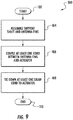
- a method for making the outer space deployable antenna 30 is illustrated generally at 100 .
- the process starts (Block 102) and a support shaft 32 and plurality of antenna fins 34 are assembled together (Block 104) adjacent the support shaft.
- the at least one draw cord 40 is coupled between the plurality of antenna fins 34 and actuator 36 (Block 106).
- the draw cord 40 is then tied down to the respective endpoints, which could be both ends tied and connected to the collar 66 that displaces axially upon electric motor activation (Block 108).
- the process ends at Block 110.
Landscapes
- Engineering & Computer Science (AREA)
- Remote Sensing (AREA)
- Aviation & Aerospace Engineering (AREA)
- Physics & Mathematics (AREA)
- Astronomy & Astrophysics (AREA)
- General Physics & Mathematics (AREA)
- Electromagnetism (AREA)
- Details Of Aerials (AREA)
Applications Claiming Priority (1)
| Application Number | Priority Date | Filing Date | Title |
|---|---|---|---|
| US16/452,630 US11177576B2 (en) | 2019-06-26 | 2019-06-26 | Antenna having deployable antenna fins and associated methods |
Publications (2)
| Publication Number | Publication Date |
|---|---|
| EP3761443A1 true EP3761443A1 (fr) | 2021-01-06 |
| EP3761443B1 EP3761443B1 (fr) | 2025-01-22 |
Family
ID=70977380
Family Applications (1)
| Application Number | Title | Priority Date | Filing Date |
|---|---|---|---|
| EP20177949.3A Active EP3761443B1 (fr) | 2019-06-26 | 2020-06-03 | Antenne ayant des ailettes d'antenne déployables et procédés associés |
Country Status (2)
| Country | Link |
|---|---|
| US (1) | US11177576B2 (fr) |
| EP (1) | EP3761443B1 (fr) |
Families Citing this family (7)
| Publication number | Priority date | Publication date | Assignee | Title |
|---|---|---|---|---|
| US11237277B2 (en) | 2019-02-15 | 2022-02-01 | Horizon Technologies Consultants, Ltd. | Techniques for determining geolocations |
| DE102019109810B4 (de) * | 2019-04-12 | 2023-01-19 | Deutsches Zentrum für Luft- und Raumfahrt e.V. | Vorrichtung und Verfahren zum Entfalten eines aufgerollten länglichen Hohlkörpers |
| CA3189429A1 (fr) * | 2020-08-14 | 2022-02-17 | Mark Allen BAILEY | Systeme de surface d'orientation de rayonnement electromagnetique deployable avec actionneurs |
| WO2022036279A1 (fr) | 2020-08-14 | 2022-02-17 | M.M.A. Design, LLC | Système de lentille d'orientation de rayonnement électromagnétique déployable |
| US11742562B2 (en) * | 2021-04-23 | 2023-08-29 | M.M.A. Design, LLC | Deployable antenna system |
| CN114256628B (zh) * | 2021-12-10 | 2023-12-15 | 武汉船舶通信研究所(中国船舶重工集团公司第七二二研究所) | 一种小型化短波软振子对数周期天线 |
| US12296986B2 (en) * | 2022-01-07 | 2025-05-13 | Northrop Grumman Systems Corporation | Deployable panel array and related assemblies and methods |
Citations (6)
| Publication number | Priority date | Publication date | Assignee | Title |
|---|---|---|---|---|
| US4262293A (en) * | 1978-10-11 | 1981-04-14 | Gernal Dynamics (Convair) | Deployable log periodic VEE antenna |
| US4315265A (en) * | 1980-06-11 | 1982-02-09 | Trw Inc. | Rigid collapsible dish structure |
| US5635946A (en) * | 1994-12-29 | 1997-06-03 | Francis; Aaron | Stowable, deployable, retractable antenna |
| US5642122A (en) * | 1991-11-08 | 1997-06-24 | Teledesic Corporation | Spacecraft antennas and beam steering methods for satellite communciation system |
| US20070145195A1 (en) * | 2005-12-23 | 2007-06-28 | Northrop Grumman Space & Mission Systems Corporation | Deployable array support structure |
| EP3270462A2 (fr) * | 2017-10-06 | 2018-01-17 | RF Venue, Inc. | Antenne de diversité à ailettes |
Family Cites Families (10)
| Publication number | Priority date | Publication date | Assignee | Title |
|---|---|---|---|---|
| US3286268A (en) | 1964-01-02 | 1966-11-15 | Sylvania Electric Prod | Log periodic antenna with parasitic elements interspersed in log periodic manner |
| US4286271A (en) | 1979-02-26 | 1981-08-25 | Gte Products Corporation | Log-periodic monopole antenna |
| US4296416A (en) * | 1979-10-26 | 1981-10-20 | E-Systems, Inc. | Dual mode log periodic monopole array |
| US4763131A (en) | 1987-02-26 | 1988-08-09 | Gte Government Systems Corporation | Log-periodic monopole antenna array |
| US7126553B1 (en) | 2003-10-02 | 2006-10-24 | The United States Of America As Represented By The Administrator Of The National Aeronautics And Space Administration | Deployable antenna |
| US8836593B2 (en) | 2010-08-03 | 2014-09-16 | RF Venue, Inc | Diversity fin antenna |
| FR2983646B1 (fr) | 2011-12-02 | 2014-06-27 | Thales Sa | Systeme a antenne deployable pour satellite et procede de deploiement |
| US9555904B2 (en) | 2012-08-09 | 2017-01-31 | Analytical Mechanics Associates, Inc. | Gossamer apparatus and systems for use with spacecraft |
| US10411363B2 (en) * | 2017-05-15 | 2019-09-10 | The Boeing Company | Foldable dipole array antennas |
| EP3900110B1 (fr) * | 2018-12-20 | 2025-03-19 | Tendeg LLC | Système d'antennes |
-
2019
- 2019-06-26 US US16/452,630 patent/US11177576B2/en active Active
-
2020
- 2020-06-03 EP EP20177949.3A patent/EP3761443B1/fr active Active
Patent Citations (6)
| Publication number | Priority date | Publication date | Assignee | Title |
|---|---|---|---|---|
| US4262293A (en) * | 1978-10-11 | 1981-04-14 | Gernal Dynamics (Convair) | Deployable log periodic VEE antenna |
| US4315265A (en) * | 1980-06-11 | 1982-02-09 | Trw Inc. | Rigid collapsible dish structure |
| US5642122A (en) * | 1991-11-08 | 1997-06-24 | Teledesic Corporation | Spacecraft antennas and beam steering methods for satellite communciation system |
| US5635946A (en) * | 1994-12-29 | 1997-06-03 | Francis; Aaron | Stowable, deployable, retractable antenna |
| US20070145195A1 (en) * | 2005-12-23 | 2007-06-28 | Northrop Grumman Space & Mission Systems Corporation | Deployable array support structure |
| EP3270462A2 (fr) * | 2017-10-06 | 2018-01-17 | RF Venue, Inc. | Antenne de diversité à ailettes |
Also Published As
| Publication number | Publication date |
|---|---|
| US11177576B2 (en) | 2021-11-16 |
| US20200411998A1 (en) | 2020-12-31 |
| EP3761443B1 (fr) | 2025-01-22 |
Similar Documents
| Publication | Publication Date | Title |
|---|---|---|
| EP3761443B1 (fr) | Antenne ayant des ailettes d'antenne déployables et procédés associés | |
| Shah et al. | Lightweight and low-cost deployable origami antennas—A review | |
| US10826157B2 (en) | Deployable reflectarray antenna structure | |
| US7126553B1 (en) | Deployable antenna | |
| US5227808A (en) | Wide-band L-band corporate fed antenna for space based radars | |
| Lokman et al. | A review of antennas for picosatellite applications | |
| US10020586B1 (en) | Segmented helical antenna with reconfigurable polarization | |
| US10938109B2 (en) | Foldable and reconfigurable antennas, arrays and frequency selective surfaces with rigid panels | |
| US12355132B2 (en) | Deployable antenna system | |
| US11362427B2 (en) | Deployable horn antenna and associated methods | |
| Ochoa et al. | Deployable helical antenna for nano-satellites | |
| EP3764464B1 (fr) | Antenne déployable dans un espace conique et procédés associés | |
| Gómez‐Guillamón Buendía et al. | Review of antenna technologies for very high frequency data exchange systems | |
| Ghaderi et al. | Cubesat antenna designs in the last 2 decades (2002–2023): a survey | |
| Sanad et al. | A sub-6 GHz multi-beam base station antenna for 5G with an arbitrary beam-tilting for each beam | |
| US4743917A (en) | Apparatus and method for a portable roll-out antenna | |
| Uddin et al. | The Evolutions of Reflectarray Antennas for Small Satellites: Navigating to Design, Fabrication and Performance Techniques | |
| Tariq et al. | Conformal circularly polarized UHF slot antenna for CubeSat missions | |
| US7151509B2 (en) | Apparatus for use in providing wireless communication and method for use and deployment of such apparatus | |
| US10931022B1 (en) | Reconfigurable arrays with multiple unit cells | |
| Shah et al. | Origami Antennas for Wireless Communication Systems | |
| Costantine et al. | Deployable antenna concepts for CubeSats | |
| Surendran et al. | Literature review on numerous antenna for small satellites-CubeSats | |
| Ta et al. | A Planar Wideband Two-Level Sequentially Rotated Array Antenna for X-Band CubeSat | |
| Castro et al. | Design and Build Process of a Small Satellite Deployable UHF Antenna |
Legal Events
| Date | Code | Title | Description |
|---|---|---|---|
| PUAI | Public reference made under article 153(3) epc to a published international application that has entered the european phase |
Free format text: ORIGINAL CODE: 0009012 |
|
| STAA | Information on the status of an ep patent application or granted ep patent |
Free format text: STATUS: REQUEST FOR EXAMINATION WAS MADE |
|
| 17P | Request for examination filed |
Effective date: 20200603 |
|
| AK | Designated contracting states |
Kind code of ref document: A1 Designated state(s): AL AT BE BG CH CY CZ DE DK EE ES FI FR GB GR HR HU IE IS IT LI LT LU LV MC MK MT NL NO PL PT RO RS SE SI SK SM TR |
|
| AX | Request for extension of the european patent |
Extension state: BA ME |
|
| STAA | Information on the status of an ep patent application or granted ep patent |
Free format text: STATUS: EXAMINATION IS IN PROGRESS |
|
| 17Q | First examination report despatched |
Effective date: 20221220 |
|
| REG | Reference to a national code |
Ref country code: DE Ref legal event code: R079 Free format text: PREVIOUS MAIN CLASS: H01Q0001080000 Ipc: B64G0001660000 Ref country code: DE Ref legal event code: R079 Ref document number: 602020045057 Country of ref document: DE Free format text: PREVIOUS MAIN CLASS: H01Q0001080000 Ipc: B64G0001660000 |
|
| REG | Reference to a national code |
Ref country code: DE Ref legal event code: R079 Free format text: PREVIOUS MAIN CLASS: B64G0001660000 Ipc: H01Q0001280000 Ref country code: DE Ref legal event code: R079 Ref document number: 602020045057 Country of ref document: DE Free format text: PREVIOUS MAIN CLASS: B64G0001660000 Ipc: H01Q0001280000 |
|
| RIC1 | Information provided on ipc code assigned before grant |
Ipc: H01Q 1/08 20060101ALI20240909BHEP Ipc: H01Q 5/25 20150101ALI20240909BHEP Ipc: H01Q 21/28 20060101ALI20240909BHEP Ipc: H01Q 21/20 20060101ALI20240909BHEP Ipc: H01Q 1/28 20060101ALI20240909BHEP Ipc: B64G 1/22 20060101ALI20240909BHEP Ipc: B64G 1/10 20060101ALI20240909BHEP Ipc: B64G 1/66 20060101AFI20240909BHEP |
|
| GRAP | Despatch of communication of intention to grant a patent |
Free format text: ORIGINAL CODE: EPIDOSNIGR1 |
|
| STAA | Information on the status of an ep patent application or granted ep patent |
Free format text: STATUS: GRANT OF PATENT IS INTENDED |
|
| RIC1 | Information provided on ipc code assigned before grant |
Ipc: B64G 1/10 20060101ALN20241015BHEP Ipc: H01Q 5/25 20150101ALN20241015BHEP Ipc: B64G 1/22 20060101ALI20241015BHEP Ipc: B64G 1/66 20060101ALI20241015BHEP Ipc: H01Q 21/20 20060101ALI20241015BHEP Ipc: H01Q 1/08 20060101ALI20241015BHEP Ipc: H01Q 1/28 20060101AFI20241015BHEP |
|
| INTG | Intention to grant announced |
Effective date: 20241025 |
|
| GRAS | Grant fee paid |
Free format text: ORIGINAL CODE: EPIDOSNIGR3 |
|
| GRAA | (expected) grant |
Free format text: ORIGINAL CODE: 0009210 |
|
| STAA | Information on the status of an ep patent application or granted ep patent |
Free format text: STATUS: THE PATENT HAS BEEN GRANTED |
|
| AK | Designated contracting states |
Kind code of ref document: B1 Designated state(s): AL AT BE BG CH CY CZ DE DK EE ES FI FR GB GR HR HU IE IS IT LI LT LU LV MC MK MT NL NO PL PT RO RS SE SI SK SM TR |
|
| P01 | Opt-out of the competence of the unified patent court (upc) registered |
Free format text: CASE NUMBER: APP_66699/2024 Effective date: 20241217 |
|
| REG | Reference to a national code |
Ref country code: GB Ref legal event code: FG4D |
|
| REG | Reference to a national code |
Ref country code: CH Ref legal event code: EP |
|
| REG | Reference to a national code |
Ref country code: IE Ref legal event code: FG4D |
|
| REG | Reference to a national code |
Ref country code: DE Ref legal event code: R096 Ref document number: 602020045057 Country of ref document: DE |
|
| REG | Reference to a national code |
Ref country code: NL Ref legal event code: MP Effective date: 20250122 |
|
| PG25 | Lapsed in a contracting state [announced via postgrant information from national office to epo] |
Ref country code: NL Free format text: LAPSE BECAUSE OF FAILURE TO SUBMIT A TRANSLATION OF THE DESCRIPTION OR TO PAY THE FEE WITHIN THE PRESCRIBED TIME-LIMIT Effective date: 20250122 |
|
| PG25 | Lapsed in a contracting state [announced via postgrant information from national office to epo] |
Ref country code: RS Free format text: LAPSE BECAUSE OF FAILURE TO SUBMIT A TRANSLATION OF THE DESCRIPTION OR TO PAY THE FEE WITHIN THE PRESCRIBED TIME-LIMIT Effective date: 20250422 |
|
| PG25 | Lapsed in a contracting state [announced via postgrant information from national office to epo] |
Ref country code: FI Free format text: LAPSE BECAUSE OF FAILURE TO SUBMIT A TRANSLATION OF THE DESCRIPTION OR TO PAY THE FEE WITHIN THE PRESCRIBED TIME-LIMIT Effective date: 20250122 |
|
| PG25 | Lapsed in a contracting state [announced via postgrant information from national office to epo] |
Ref country code: PL Free format text: LAPSE BECAUSE OF FAILURE TO SUBMIT A TRANSLATION OF THE DESCRIPTION OR TO PAY THE FEE WITHIN THE PRESCRIBED TIME-LIMIT Effective date: 20250122 |
|
| PGFP | Annual fee paid to national office [announced via postgrant information from national office to epo] |
Ref country code: DE Payment date: 20250627 Year of fee payment: 6 |
|
| PG25 | Lapsed in a contracting state [announced via postgrant information from national office to epo] |
Ref country code: ES Free format text: LAPSE BECAUSE OF FAILURE TO SUBMIT A TRANSLATION OF THE DESCRIPTION OR TO PAY THE FEE WITHIN THE PRESCRIBED TIME-LIMIT Effective date: 20250122 |
|
| PGFP | Annual fee paid to national office [announced via postgrant information from national office to epo] |
Ref country code: GB Payment date: 20250627 Year of fee payment: 6 |
|
| REG | Reference to a national code |
Ref country code: LT Ref legal event code: MG9D |
|
| PG25 | Lapsed in a contracting state [announced via postgrant information from national office to epo] |
Ref country code: NO Free format text: LAPSE BECAUSE OF FAILURE TO SUBMIT A TRANSLATION OF THE DESCRIPTION OR TO PAY THE FEE WITHIN THE PRESCRIBED TIME-LIMIT Effective date: 20250422 Ref country code: IS Free format text: LAPSE BECAUSE OF FAILURE TO SUBMIT A TRANSLATION OF THE DESCRIPTION OR TO PAY THE FEE WITHIN THE PRESCRIBED TIME-LIMIT Effective date: 20250522 |
|
| REG | Reference to a national code |
Ref country code: AT Ref legal event code: MK05 Ref document number: 1762171 Country of ref document: AT Kind code of ref document: T Effective date: 20250122 |
|
| PG25 | Lapsed in a contracting state [announced via postgrant information from national office to epo] |
Ref country code: HR Free format text: LAPSE BECAUSE OF FAILURE TO SUBMIT A TRANSLATION OF THE DESCRIPTION OR TO PAY THE FEE WITHIN THE PRESCRIBED TIME-LIMIT Effective date: 20250122 |
|
| PG25 | Lapsed in a contracting state [announced via postgrant information from national office to epo] |
Ref country code: PT Free format text: LAPSE BECAUSE OF FAILURE TO SUBMIT A TRANSLATION OF THE DESCRIPTION OR TO PAY THE FEE WITHIN THE PRESCRIBED TIME-LIMIT Effective date: 20250522 Ref country code: LV Free format text: LAPSE BECAUSE OF FAILURE TO SUBMIT A TRANSLATION OF THE DESCRIPTION OR TO PAY THE FEE WITHIN THE PRESCRIBED TIME-LIMIT Effective date: 20250122 |
|
| PG25 | Lapsed in a contracting state [announced via postgrant information from national office to epo] |
Ref country code: BG Free format text: LAPSE BECAUSE OF FAILURE TO SUBMIT A TRANSLATION OF THE DESCRIPTION OR TO PAY THE FEE WITHIN THE PRESCRIBED TIME-LIMIT Effective date: 20250122 Ref country code: GR Free format text: LAPSE BECAUSE OF FAILURE TO SUBMIT A TRANSLATION OF THE DESCRIPTION OR TO PAY THE FEE WITHIN THE PRESCRIBED TIME-LIMIT Effective date: 20250423 |
|
| PG25 | Lapsed in a contracting state [announced via postgrant information from national office to epo] |
Ref country code: AT Free format text: LAPSE BECAUSE OF FAILURE TO SUBMIT A TRANSLATION OF THE DESCRIPTION OR TO PAY THE FEE WITHIN THE PRESCRIBED TIME-LIMIT Effective date: 20250122 |
|
| PG25 | Lapsed in a contracting state [announced via postgrant information from national office to epo] |
Ref country code: SE Free format text: LAPSE BECAUSE OF FAILURE TO SUBMIT A TRANSLATION OF THE DESCRIPTION OR TO PAY THE FEE WITHIN THE PRESCRIBED TIME-LIMIT Effective date: 20250122 |
|
| PG25 | Lapsed in a contracting state [announced via postgrant information from national office to epo] |
Ref country code: SM Free format text: LAPSE BECAUSE OF FAILURE TO SUBMIT A TRANSLATION OF THE DESCRIPTION OR TO PAY THE FEE WITHIN THE PRESCRIBED TIME-LIMIT Effective date: 20250122 |
|
| PG25 | Lapsed in a contracting state [announced via postgrant information from national office to epo] |
Ref country code: DK Free format text: LAPSE BECAUSE OF FAILURE TO SUBMIT A TRANSLATION OF THE DESCRIPTION OR TO PAY THE FEE WITHIN THE PRESCRIBED TIME-LIMIT Effective date: 20250122 |
|
| PG25 | Lapsed in a contracting state [announced via postgrant information from national office to epo] |
Ref country code: IT Free format text: LAPSE BECAUSE OF FAILURE TO SUBMIT A TRANSLATION OF THE DESCRIPTION OR TO PAY THE FEE WITHIN THE PRESCRIBED TIME-LIMIT Effective date: 20250122 |
|
| PG25 | Lapsed in a contracting state [announced via postgrant information from national office to epo] |
Ref country code: EE Free format text: LAPSE BECAUSE OF FAILURE TO SUBMIT A TRANSLATION OF THE DESCRIPTION OR TO PAY THE FEE WITHIN THE PRESCRIBED TIME-LIMIT Effective date: 20250122 Ref country code: CZ Free format text: LAPSE BECAUSE OF FAILURE TO SUBMIT A TRANSLATION OF THE DESCRIPTION OR TO PAY THE FEE WITHIN THE PRESCRIBED TIME-LIMIT Effective date: 20250122 |
|
| REG | Reference to a national code |
Ref country code: DE Ref legal event code: R097 Ref document number: 602020045057 Country of ref document: DE |
|
| PG25 | Lapsed in a contracting state [announced via postgrant information from national office to epo] |
Ref country code: RO Free format text: LAPSE BECAUSE OF FAILURE TO SUBMIT A TRANSLATION OF THE DESCRIPTION OR TO PAY THE FEE WITHIN THE PRESCRIBED TIME-LIMIT Effective date: 20250122 |
|
| PG25 | Lapsed in a contracting state [announced via postgrant information from national office to epo] |
Ref country code: SK Free format text: LAPSE BECAUSE OF FAILURE TO SUBMIT A TRANSLATION OF THE DESCRIPTION OR TO PAY THE FEE WITHIN THE PRESCRIBED TIME-LIMIT Effective date: 20250122 |
|
| PLBE | No opposition filed within time limit |
Free format text: ORIGINAL CODE: 0009261 |
|
| STAA | Information on the status of an ep patent application or granted ep patent |
Free format text: STATUS: NO OPPOSITION FILED WITHIN TIME LIMIT |
|
| REG | Reference to a national code |
Ref country code: CH Ref legal event code: L10 Free format text: ST27 STATUS EVENT CODE: U-0-0-L10-L00 (AS PROVIDED BY THE NATIONAL OFFICE) Effective date: 20251203 |
|
| 26N | No opposition filed |
Effective date: 20251023 |
|
| REG | Reference to a national code |
Ref country code: CH Ref legal event code: H13 Free format text: ST27 STATUS EVENT CODE: U-0-0-H10-H13 (AS PROVIDED BY THE NATIONAL OFFICE) Effective date: 20260127 |
|
| PG25 | Lapsed in a contracting state [announced via postgrant information from national office to epo] |
Ref country code: MC Free format text: LAPSE BECAUSE OF FAILURE TO SUBMIT A TRANSLATION OF THE DESCRIPTION OR TO PAY THE FEE WITHIN THE PRESCRIBED TIME-LIMIT Effective date: 20250122 |
|
| PG25 | Lapsed in a contracting state [announced via postgrant information from national office to epo] |
Ref country code: LU Free format text: LAPSE BECAUSE OF NON-PAYMENT OF DUE FEES Effective date: 20250603 |
|
| REG | Reference to a national code |
Ref country code: BE Ref legal event code: MM Effective date: 20250630 |
|
| PG25 | Lapsed in a contracting state [announced via postgrant information from national office to epo] |
Ref country code: IE Free format text: LAPSE BECAUSE OF NON-PAYMENT OF DUE FEES Effective date: 20250603 |
|
| PG25 | Lapsed in a contracting state [announced via postgrant information from national office to epo] |
Ref country code: BE Free format text: LAPSE BECAUSE OF NON-PAYMENT OF DUE FEES Effective date: 20250630 |
|
| PG25 | Lapsed in a contracting state [announced via postgrant information from national office to epo] |
Ref country code: FR Free format text: LAPSE BECAUSE OF NON-PAYMENT OF DUE FEES Effective date: 20250630 |
|
| PG25 | Lapsed in a contracting state [announced via postgrant information from national office to epo] |
Ref country code: CH Free format text: LAPSE BECAUSE OF NON-PAYMENT OF DUE FEES Effective date: 20250630 |