EP3761455B1 - Verbindungsstecker mit zentralem stift und lamellenhülse und einer verbindungsbuchse mit lamellenhülse - Google Patents
Verbindungsstecker mit zentralem stift und lamellenhülse und einer verbindungsbuchse mit lamellenhülse Download PDFInfo
- Publication number
- EP3761455B1 EP3761455B1 EP19183650.1A EP19183650A EP3761455B1 EP 3761455 B1 EP3761455 B1 EP 3761455B1 EP 19183650 A EP19183650 A EP 19183650A EP 3761455 B1 EP3761455 B1 EP 3761455B1
- Authority
- EP
- European Patent Office
- Prior art keywords
- lamellae
- lamella sleeve
- lamella
- sleeve
- central pin
- Prior art date
- Legal status (The legal status is an assumption and is not a legal conclusion. Google has not performed a legal analysis and makes no representation as to the accuracy of the status listed.)
- Active
Links
Images




Classifications
-
- H—ELECTRICITY
- H01—ELECTRIC ELEMENTS
- H01R—ELECTRICALLY-CONDUCTIVE CONNECTIONS; STRUCTURAL ASSOCIATIONS OF A PLURALITY OF MUTUALLY-INSULATED ELECTRICAL CONNECTING ELEMENTS; COUPLING DEVICES; CURRENT COLLECTORS
- H01R13/00—Details of coupling devices of the kinds covered by groups H01R12/70 or H01R24/00 - H01R33/00
- H01R13/02—Contact members
- H01R13/04—Pins or blades for co-operation with sockets
- H01R13/05—Resilient pins or blades
- H01R13/052—Resilient pins or blades co-operating with sockets having a circular transverse section
-
- H—ELECTRICITY
- H01—ELECTRIC ELEMENTS
- H01R—ELECTRICALLY-CONDUCTIVE CONNECTIONS; STRUCTURAL ASSOCIATIONS OF A PLURALITY OF MUTUALLY-INSULATED ELECTRICAL CONNECTING ELEMENTS; COUPLING DEVICES; CURRENT COLLECTORS
- H01R13/00—Details of coupling devices of the kinds covered by groups H01R12/70 or H01R24/00 - H01R33/00
- H01R13/46—Bases; Cases
- H01R13/52—Dustproof, splashproof, drip-proof, waterproof, or flameproof cases
- H01R13/5219—Sealing means between coupling parts, e.g. interfacial seal
-
- H—ELECTRICITY
- H01—ELECTRIC ELEMENTS
- H01R—ELECTRICALLY-CONDUCTIVE CONNECTIONS; STRUCTURAL ASSOCIATIONS OF A PLURALITY OF MUTUALLY-INSULATED ELECTRICAL CONNECTING ELEMENTS; COUPLING DEVICES; CURRENT COLLECTORS
- H01R13/00—Details of coupling devices of the kinds covered by groups H01R12/70 or H01R24/00 - H01R33/00
- H01R13/02—Contact members
- H01R13/10—Sockets for co-operation with pins or blades
- H01R13/11—Resilient sockets
- H01R13/111—Resilient sockets co-operating with pins having a circular transverse section
-
- H—ELECTRICITY
- H01—ELECTRIC ELEMENTS
- H01R—ELECTRICALLY-CONDUCTIVE CONNECTIONS; STRUCTURAL ASSOCIATIONS OF A PLURALITY OF MUTUALLY-INSULATED ELECTRICAL CONNECTING ELEMENTS; COUPLING DEVICES; CURRENT COLLECTORS
- H01R13/00—Details of coupling devices of the kinds covered by groups H01R12/70 or H01R24/00 - H01R33/00
- H01R13/02—Contact members
- H01R13/15—Pins, blades or sockets having separate spring member for producing or increasing contact pressure
- H01R13/17—Pins, blades or sockets having separate spring member for producing or increasing contact pressure with spring member on the pin
-
- H—ELECTRICITY
- H01—ELECTRIC ELEMENTS
- H01R—ELECTRICALLY-CONDUCTIVE CONNECTIONS; STRUCTURAL ASSOCIATIONS OF A PLURALITY OF MUTUALLY-INSULATED ELECTRICAL CONNECTING ELEMENTS; COUPLING DEVICES; CURRENT COLLECTORS
- H01R13/00—Details of coupling devices of the kinds covered by groups H01R12/70 or H01R24/00 - H01R33/00
- H01R13/02—Contact members
- H01R13/15—Pins, blades or sockets having separate spring member for producing or increasing contact pressure
- H01R13/187—Pins, blades or sockets having separate spring member for producing or increasing contact pressure with spring member in the socket
-
- H—ELECTRICITY
- H01—ELECTRIC ELEMENTS
- H01R—ELECTRICALLY-CONDUCTIVE CONNECTIONS; STRUCTURAL ASSOCIATIONS OF A PLURALITY OF MUTUALLY-INSULATED ELECTRICAL CONNECTING ELEMENTS; COUPLING DEVICES; CURRENT COLLECTORS
- H01R13/00—Details of coupling devices of the kinds covered by groups H01R12/70 or H01R24/00 - H01R33/00
- H01R13/02—Contact members
- H01R13/193—Means for increasing contact pressure at the end of engagement of coupling part, e.g. zero insertion force or no friction
-
- H—ELECTRICITY
- H01—ELECTRIC ELEMENTS
- H01R—ELECTRICALLY-CONDUCTIVE CONNECTIONS; STRUCTURAL ASSOCIATIONS OF A PLURALITY OF MUTUALLY-INSULATED ELECTRICAL CONNECTING ELEMENTS; COUPLING DEVICES; CURRENT COLLECTORS
- H01R24/00—Two-part coupling devices, or either of their cooperating parts, characterised by their overall structure
-
- H—ELECTRICITY
- H01—ELECTRIC ELEMENTS
- H01R—ELECTRICALLY-CONDUCTIVE CONNECTIONS; STRUCTURAL ASSOCIATIONS OF A PLURALITY OF MUTUALLY-INSULATED ELECTRICAL CONNECTING ELEMENTS; COUPLING DEVICES; CURRENT COLLECTORS
- H01R43/00—Apparatus or processes specially adapted for manufacturing, assembling, maintaining, or repairing of line connectors or current collectors or for joining electric conductors
Definitions
- the invention relates to a connecting plug comprising a central pin and a lamella sleeve.
- the invention further relates to a plug-in connector comprising a connecting plug and a corresponding socket.
- the invention further relates to a connecting socket comprising a socket element and a lamella sleeve.
- German patent DE 38 08 632 C1 describes a coaxial plug-in connector with an inner conductor plug connection.
- the inner conductor plug connection comprises a rigid, metallic socket part and a plug part, wherein the plug part's front portion, which is insertable in the socket part, has a reduced outer diameter and ends at an annular shoulder which forms a stop for the edge of the socket part.
- a contact pot As the front portion of the plug part is enclosed by a contact pot, an accurate centrical fit of the plug part in the socket part and a consistently good contact along the circumference is accomplished.
- the bottom of the contact pot is tightly connected to the end face of the plug part, whereas the wall of the contact pot has a configuration that is resilient in radial direction, the configuration being chosen such that the largest outer diameter lies in the area of the contact pot's edge.
- German patent application DE 100 41 516 A1 describes an electrical connection device for high currents.
- the electrical connection device comprises a receptacle for an electrical conductor to which the connection device is to be permanently attached, and a resilient plug contact comprising a plurality of resilient lamellae for connection to a mating connector.
- the receptacle and the plug contact are made of separate parts and these parts are non-detachably connected by means of a rivet connection.
- a female electrical connector includes a housing defining a generally cylindrical bore therewithin.
- the connector includes a contact cage disposed, and retained, within the housing.
- the contact cage includes a number of contact blades disposed so as to provide a radial resilience.
- the connector provides a high current capacity, low insertion force connector which may be readily fit over post-type electrical terminals.
- a spring contact jack and spring plug pin are known that have a plurality of mutually laterally disposed spring contacts which can be attached at one end to a support piece and which are radially curved in order to provide contact with an opposing contact.
- German patent application DE 199 09 107 A1 discloses an RF coaxial connector plug with a slot-free outer conductor sleeve that carries a spring ring on the outside of its free end.
- the spring ring due to circumferential longitudinal slots consist of a plurality of spring plates with a ring base common to them.
- the spring plates of the spring ring on the ring base are slightly bent radially outwards.
- a spring connector that includes a movable pin, a conductive tube accommodating a base portion of the movable pin, a spring provided in the conductive tube so as to urge the movable pin in a direction, in which the movable pin protrudes from the conductive tube, and a plate spring contact including a plurality of plate springs that electrically connect the movable pin and the conductive tube to each other.
- the plurality of plate springs are provided around an entire circumference of the movable pin and are in elastic contact with an inner circumferential surface of the conductive tube, respectively.
- German Utility model DE 296 01 407 U1 describes a coaxial plug for plugging onto a socket, consisting of a pin-shaped inner pole and an outer pole surrounding it in a ring shape.
- the outer pole is designed to be elastically flexible and serves to radially clamp the plug and socket.
- outer pole has, along its circumference, approximately axially extending slots which penetrate the outer pole wall, so that adjacent pressure tongues are formed.
- the outer pole has an annular spring element on its outside.
- a plug and a socket are known that comprises an annular plug or socket part and a lamella basket.
- the lamella basket comprises a plurality of lamellae and an annular carrier strip located at the rear part of the lamella basket.
- Each of the lamellae has a first end being firmly attached to or integrally moulded with the annular carrier strip and a second end being implemented as a free end.
- US patent application publication US 2002/0049005 A1 relates to an electrical high-current connection device comprising a receptacle for an electrical conductor to which conductor the connection device is to be permanently fastened.
- the device further comprises an elastic plug contact for being connected with a counterplug.
- the receptacle and the plug contact are formed of separate parts which are non-detachably fastened to each other.
- a connector terminal in the form of a socket contact has a cylindrical socket body (32) with a tubular spring contact (34) inserted therein.
- the spring contact (34) has a rear portion (46) which establishes a press fit with the socket body (32), the socket body (32) may be crimped (59) over the rear portion (46) to more securely hold the spring contact (34) in the socket body (32).
- the spring contact (34) further has a plurality of fingers (50) which taper forwardly and inwardly to resiliently grab a male pin as it enters the socket contact.
- the object of the invention is to provide a connecting plug or a connecting socket comprising a plurality of resilient lamellae, wherein the manufacturing of the connecting plug or the connecting socket is simplified.
- a connecting plug according to claim 1 is provided.
- the connecting plug comprises a central pin and a lamella sleeve, with the lamella sleeve comprising a front opening, a rear opening and a plurality of lamellae.
- the lamella sleeve circumferentially encloses an axial segment of the central pin and the lamella sleeve is fixed to the central pin.
- the central pin extends through the rear opening, through the lamella sleeve and through the front opening of the lamella sleeve.
- the connecting plug of the present invention is produced by assembling the central pin and the lamella sleeve.
- the lamella sleeve may for example be slid onto the front portion of the central pin such that the central pin extends through the rear opening, the lamella sleeve and the front opening. In this position, the lamella sleeve encloses an axial segment of the central pin.
- An axial segment of the central pin is a portion of the central pin that has a certain extension in the connecting plug's mating direction.
- the front end of the central pin may for example be shaped as a tip that extends beyond the front opening of the lamella sleeve.
- the plug-in connector with resilient lamellae is obtained by assembling two parts.
- Each of the two parts can be manufactured using a manufacturing technique that is particularly suitable for the respective part.
- a manufacturing technique For example, for manufacturing the lamella sleeve, a different manufacturing technique may be used than for manufacturing the central pin.
- the advantages of two different techniques can be combined.
- Each of the two parts can be produced in large quantities at low cost. For this reason, the plug-in connector of the present invention can be produced in a cost-effective manner.
- front portion In the present application, terms such as "front portion”, “front end”, “front opening”, “rear end”, “rear opening”, “rear edge” relate to the connecting plug's mating direction.
- the mating direction is the direction in which the plug is inserted into a socket. Accordingly, the front end of the connecting plug is the part of the plug that is inserted into the socket first.
- the connecting plug comprises a central pin and a lamella sleeve, with the lamella sleeve comprising a front opening, a rear opening, an annular carrier part and a plurality of lamellae.
- the central pin extends through the rear opening of the lamella sleeve and at least partly through the lamella sleeve, with the lamella sleeve circumferentially enclosing an axial segment of the central pin.
- the lamella sleeve is fixed to the central pin.
- the annular carrier part is located at a rear portion and the lamellae are located at a front portion of the lamella sleeve, wherein each of the lamellae has a first end coupled to the annular carrier part and a second end that is implemented as a free end, with the free ends of the lamellae facing towards the front end of the connecting plug.
- the connecting plug of the present invention is produced by assembling two parts, a central pin and a lamella sleeve.
- the lamella sleeve is slid onto the central pin such that the central pin extends through the rear opening of the lamella sleeve and at least partly through the lamella sleeve.
- the lamella sleeve encloses an axial segment of the central pin.
- an axial segment is a portion of the central pin having a certain extension in the connecting plug's mating direction.
- the lamellae are located at a front portion of the lamella sleeve.
- Each of the lamellae has a free end and a fixed end, with the free end facing towards the connecting plug's front end.
- the lamellae are resiliently deformed right at the beginning of the insertion process.
- a certain resistance has to be overcome, which provides a tactile feedback to the user.
- the electrical contact with the socket is established right at the beginning of the insertion process.
- Yet another advantage of the connecting plug is that the axial position of the lamellae's contact points is exactly defined. As a consequence, during the insertion process, electrical contact is established at a well-defined point of the insertion process.
- the connecting plug of the present invention is produced by assembling a central pin and a lamella sleeve.
- Each of these two parts can be produced using a suitable manufacturing technique.
- the advantages of different manufacturing techniques can be combined.
- Each of the two parts can be manufactured in large quantities at low cost.
- a plug-in connector comprising a connecting plug as described above and a corresponding socket.
- the connecting plug may be formed by assembling a central pin and a lamella sleeve.
- the lamella sleeve comprises a front opening, a rear opening and a plurality of lamellae.
- the method comprises a step of sliding the lamella sleeve on the central pin, with the central pin extending through the rear opening, through the lamella sleeve and through the front opening of the lamella sleeve, wherein the lamella sleeve circumferentially encloses an axial segment of the central pin.
- the method further comprises a step of fixing the lamella sleeve to the central pin.
- a connecting socket comprising a lamella sleeve and a socket element.
- the lamella sleeve comprises a front opening, an annular carrier part and a plurality of lamellae, wherein each of the lamellae has a first end that is integrally formed with the annular carrier part and a second end that is implemented as a free end.
- the socket element has an opening configured for accommodating at least a rear part of the lamella sleeve.
- the lamella sleeve is a deep-drawn part.
- the connecting socket of the present invention is produced by assembling a socket element and a lamella sleeve.
- the lamella sleeve is inserted into the opening of the socket element, wherein at least the rear part of the lamella sleeve is accommodated by the socket element.
- the lamella sleeve is at least partly enclosed and protected by the socket element.
- Each of the two parts, the socket element and the lamella sleeve can be produced using a suitable manufacturing technique.
- the lamella sleeve is formed by deep-drawing.
- For manufacturing the socket element a different manufacturing technique like for example turning may be used.
- Each of the parts can be manufactured in large quantities at low cost. Deep drawing is a well-suited technique for manufacturing the lamella sleeve. Deep drawing allows to manufacture the resilient lamellae of the lamella sleeve with high precision.
- a lamella sleeve that is formed as a deep-drawn part is not prone to be damaged in case a connector pin is inserted into the socket in a slanted direction or in case a tumbling motion of a connector pin occurs when the connector pin is inserted into the socket.
- a connecting plug comprising a lamella sleeve
- the lamella sleeve is of tubular shape.
- the lamella sleeve's basic shape may be a cylinder jacket of a circular cylinder. This shape of the lamella sleeve is suitable for circumferentially enclosing the central pin.
- each of the lamellae is elastically deformable in a radially inward direction of the lamella sleeve.
- the resulting spring force will be directed in a radially outwards direction.
- the lamellae When inserting the connecting plug into a socket, the lamellae will be elastically deformed in a radially inward direction and the resulting spring force will press the lamellae in a radially outwards direction against the inner surface of the socket. Due to the resilient deformation of the lamellae, the electrical contact between the plug and the socket is improved.
- the lamella sleeve and the central pin are oriented coaxially. Further preferably, the central axis of the lamella sleeve corresponds to the central axis of the central pin.
- the lamellae are located at a front portion of the lamella sleeve.
- the lamellae are deformed at the beginning of the insertion process.
- a certain resistance has to be overcome at the beginning of the insertion process, which provides a tactile feedback to the user.
- the lamella sleeve comprises a plurality of slots that extend from the lamella sleeve's front end in a predominantly axial direction towards the centre of the lamella sleeve.
- the slots may for example be configured for segmenting the front portion of the lamella sleeve into a plurality of lamellae.
- the spring force of the lamellae can be adjusted.
- the spring force of the lamellae can be adjusted as well.
- the pushing and pulling forces required for mating and unmating the connector pin and a corresponding socket can be adjusted.
- the lamellae when viewed in the mating direction of the connecting plug, are circumferentially arranged at the front portion of the lamella sleeve.
- the lamellae are configured for providing outwardly directed resilient forces.
- the lamellae extend over at least 20% of the lamella sleeve's length in the axial direction, further preferably over at least 25%, further preferably over at least 30%, further preferably over at least 35% of the lamella sleeve's length in the axial direction.
- the lamellae extend over less than 85% of the lamella sleeve's length in the axial direction, further preferably over less than 75%, further preferably over less than 60%, further preferably over less than 50%, further preferably over less than 40% of the lamella sleeve's length in the axial direction.
- Each of the lamellae has a first end coupled to an annular carrier part of the lamella sleeve and a second end that is implemented as a free end, with preferably the free ends of the lamellae facing towards the front end of the connecting plug.
- each of the lamellae has a first end coupled to an annular carrier part of the lamella sleeve and a second end that is implemented as a free end, wherein according to this alternatively preferred embodiment, the free ends of the lamellae are facing towards the rear end of the connecting plug.
- the respective first end of a lamella is integrally formed with the annular carrier part.
- the lamellae extend towards the front end of the connecting plug.
- the lamellae extend predominantly in a mating direction of the connecting plug.
- the lamellae may extend along the side faces of the connecting plug.
- the length of the lamella sleeve in the axial direction is at least 1 times the diameter, further preferably at least 1.5 times the diameter, further preferably at least 2 times the diameter.
- the length of the lamella sleeve is at most 10 times the diameter, further preferably at most 5 times the diameter, further preferably at most 3.5 times the diameter, further preferably at most 2.5 times the diameter.
- each of the lamellae comprises a bulge that extends in a radially outward direction.
- the bulge serves as a contact area and is configured for establishing an improved electrical contact between the respective lamella and the socket.
- the insertion force required for inserting the connecting plug into a corresponding socket can be varied.
- the bulges may have a rounded shape. Further preferably, in case of a bulge having a rounded shape, by varying the radius of curvature of the bulge, the insertion force required for inserting the connecting plug into the socket can be varied.
- the radius of curvature can be chosen such that for inserting the connecting plug into the socket, a well-defined insertion force has to be applied.
- the insertion behaviour when inserting the connecting plug into the socket can be modified. For example, it can be accomplished that the connecting plug can be smoothly slid into the socket.
- each lamella comprises two or more bulges that extend in a radially outward direction.
- Each of the bulges may serve as a contact area for establishing an electrical contact between the lamella and the socket.
- electrical contact between the lamella and the socket can be established at a plurality of contact areas in parallel.
- a reliable electrical contact can be established.
- each lamella comprises two or more bulges that extend in a radially outward direction, wherein electrical contact between the lamella and the socket is established via a first one of the bulges, with at least one of the remaining bulges serving as a replacement part.
- electrical contact between the lamella and the socket will be established via at least one of the remaining bulges.
- the bulges may for example have slightly different radii of curvature.
- the lamella sleeve consists of conductive material, preferably of metal.
- the lamella sleeve is formed in one piece.
- the lamella sleeve is a rotationally symmetric part.
- the lamella sleeve is a deep drawn part. Deep drawing is a suitable technique for manufacturing the resilient lamellae of the lamella sleeve with the required precision in large quantities at low costs.
- a lamella sleeve that is formed as a deep-drawn part is not prone to be damaged in case the connector pin is inserted in a slanted direction or in case a tumbling motion of the connector pin occurs during the mating process.
- the lamella sleeve is configured for being slid on the central pin.
- the central pin may for example extend through the rear opening of the lamella sleeve and at least partly through the lamella sleeve. Further preferably, the central pin may for example extend through the rear opening, through the entire lamella sleeve and through the front opening.
- the central pin comprises a circumferential recess, with the rear end of the lamella sleeve abutting against the rear end of the circumferential recess, wherein the circumferential recess is configured for determining the axial position of the lamella sleeve relative to the central pin. Accordingly, the lamella sleeve may be slid onto the central pin until the rear end of the lamella sleeve abuts against the rear end of the circumferential recess, with said recess serving as a limit stop that defines the axial position of the lamella sleeve.
- the central pin comprises a tapered portion that tapers in the axial direction towards the front end of the connecting plug.
- the lamella sleeve can be pushed onto the tapered portion and the lamella sleeve can be fixed to the central pin.
- the lamella sleeve is fixed to the central pin by means of a press fit.
- the central pin has a circular cross section.
- the lamella sleeve may for example have a ring-shaped cross section.
- the central pin consists of conductive material, preferably of metal. Further preferably, the central pin is formed in one piece. Preferably, the central pin is a solid part. According to a preferred embodiment, the central pin is a rotationally symmetric part. Preferably, the central pin is a turned part. Turning is a suitable technique for manufacturing the central pin, because the central pin is a solid part that is rotationally symmetric. For manufacturing the lamella sleeve, deep drawing is a suitable technique. By joining the central pin and the lamella sleeve, each manufactured with a different manufacturing technique, the advantages of both manufacturing techniques can be combined. In particular, the lamella sleeve may be formed by deep drawing, whereas the central pin may be formed by turning.
- the lamella sleeve is fixed to the central pin using at least one of the following joining techniques: flanging, crimping, beading, clamping, establishing a press fit.
- the central pin protrudes beyond the front end of the lamella sleeve.
- the central pin may for example comprise a tip at its front end.
- the central pin may form a tip in the portion that protrudes beyond the front end of the lamella sleeve.
- the central pin consists of at least two different components.
- the central pin comprises a contact pin and an insulating end part attached to the front end of the contact pin.
- the contact pin consists of conductive material, preferably of metal. Further preferably, the contact pin is a rotationally symmetric part. Preferably, the contact pin is a turned part.
- the insulating end part consists of insulating material. Further preferably, the insulating end part consists of one of: plastic material, an elastomer, natural rubber, synthetic rubber.
- the insulating end part is configured for providing a touch protection at the front end of the connecting plug.
- the insulating end part is fixed to the front end of the contact pin by one of the following joining techniques: screwing, caulking, establishing a press fit.
- the insulating end part comprises one or more snap-in members configured for establishing a snap-fit with the contact pin.
- the central pin comprises a contact pin and an insulating cap configured for covering a tip of the contact pin.
- the insulating cap is configured for establishing a snap-fit with the tip of the contact pin.
- the insulating cap consists of insulating material.
- the insulating cap is configured for providing a touch protection at the front end of the connecting plug.
- each of the lamellae has a first end coupled to an annular carrier part of the lamella sleeve and a second end that is implemented as a free end, with the free ends of the lamellae facing towards the front end of the connecting plug, wherein the tip is configured for protecting the free ends of the lamellae and for preventing a plastic deformation of the lamellae.
- the tip may at least partly cover the free ends of the lamellae.
- the tip may be configured for preventing damage of the lamellae.
- the central pin comprises a groove, a recess or at least one indentation.
- the central pin may for example comprise a circumferential groove or a circumferential recess.
- the groove, the recess or the at least one indentation is arranged such that a free space is provided behind the front portions of the lamellae.
- the free space behind the lamellae allows for a movement of the lamellae in the radially inwards direction. Forces acting on the lamellae cause a resilient deformation of the lamellae.
- the lamellae can absorb forces acting on them.
- the axial dimension of the groove, the recess or the at least one indentation extends beyond the free ends of the lamellae.
- the axial dimension of the groove, the recess or the at least one indentation overlaps with the front portion of the lamellae when viewed in the mating direction. If an inwardly directed force acts on the free ends of the lamellae, the free ends will be pushed into the groove, the recess or the at least one indentation.
- a respective depth of the groove, of the recess or of the at least one indentation determines a maximum deflection of the lamellae.
- the bottom of the groove, of the recess or of the at least one indentation serves as a support for the deflected lamellae.
- the bottom of the groove serves as a limit stop for limiting the deformation of the lamellae and for preventing any damages.
- the respective depth of the groove, the recess or the at least one indentation is chosen such that any plastic deformation of the lamellae is prevented. Thus, a more robust construction of the connecting plug is obtained.
- the axial position of the rear end of the groove, of the recess or of the at least one indentation relative to the lamella sleeve determines the length of the respective deformable portions of the lamellae.
- the length of the deformable portion can be adjusted.
- the deformable portions are shortened.
- the length of the deformable portion is increased.
- a rear edge of the groove, of the recess or of the at least one indentation serves as an abutting edge for the lamellae.
- the axial position of the rear end of the groove, the recess or the at least one indentation relative to the lamella sleeve determines the spring tension of the lamellae.
- the spring tension of the lamellae determines an insertion force when inserting the connecting plug into a corresponding socket.
- a plug-in connector comprising a connecting plug and a socket
- a plug-in connector comprises a connecting plug as described above and a corresponding socket.
- the socket comprises a circumferential recess or a circumferential groove configured for latching with the bulges of the connecting plug's lamellae when the connecting plug is inserted into the socket.
- the force required for unmating the connecting plug and the socket can be set to a desired value.
- a connecting socket comprising a lamella sleeve
- the lamella sleeve is of tubular shape.
- the lamella sleeve comprises a closed base at the lamella sleeve's rear end.
- a lamella sleeve with closed base can for example be formed by deep-drawing.
- each of the lamellae is elastically deformable in a radially outwards direction of the lamella sleeve.
- the resulting spring force will press the lamellae in a radially inwards direction, for example against the surface of a contact pin.
- the lamella sleeve and the socket element are oriented coaxially. Further preferably, the central axis of the lamella sleeve corresponds to the central axis of the socket element.
- the lamella sleeve comprises a plurality of slots that extend from the lamella sleeve's front end in a predominantly axial direction towards the centre of the lamella sleeve.
- the slots may for example be configured for segmenting the front portion of the lamella sleeve into a plurality of lamellae.
- the spring force of the lamellae can be adjusted.
- the lamellae when viewed in the mating direction of the connecting socket, are circumferentially arranged at the front portion of the lamella sleeve.
- the lamellae extend over at least 20% of the lamella sleeve's length in the axial direction, further preferably over at least 25%, further preferably over at least 30%, further preferably over at least 35% of the lamella sleeve's length in the axial direction.
- the lamellae extend over less than 85% of the lamella sleeve's length in the axial direction, further preferably over less than 75%, further preferably over less than 60%, further preferably over less than 50%, further preferably over less than 40% of the lamella sleeve's length in the axial direction.
- the length of the lamella sleeve in the axial direction is at least 1 times the diameter, further preferably at least 1.5 times the diameter, further preferably at least 2 times the diameter.
- the length of the lamella sleeve is at most 10 times the diameter, further preferably at most 5 times the diameter, further preferably at most 3.5 times the diameter, further preferably at most 2.5 times the diameter.
- each of the lamellae comprises a bulge that extends in a radially inward direction. Electrical contacts between the lamellae and the connector pin are established via the bulges, which serve as contact areas.
- the insertion force required for inserting a connecting plug into the connecting socket can be varied.
- the lamella sleeve consists of conductive material, preferably of metal. Yet further preferably, the lamella sleeve is a rotationally symmetric part.
- the socket element consists of conductive material, preferably of metal. Further preferably, the socket element is formed in one piece. Preferably, the socket element is a solid part. According to a preferred embodiment, the socket element is a rotationally symmetric part. Preferably, the socket element is a turned part.
- the lamella sleeve is fixed to the socket element using at least one of the following joining techniques: establishing a press fit, crimping, flanging, welding.
- the annular carrier part when viewed in the connecting socket's mating direction, is located at a rear portion and the lamellae are located at a front portion of the lamella sleeve, with the free ends of the lamellae facing towards the front end of the connecting socket.
- the advantage is that the electrical contact with a connecting plug inserted into the socket is established right at the beginning of the insertion process. Yet another advantage is that the axial position of the lamellae's contact points is exactly defined. As a consequence, during the insertion process, electrical contact is established at a well-defined point of the insertion process.
- the lamellae extend towards the front end of the connecting socket.
- the lamellae extend predominantly in a mating direction of the connecting socket.
- the annular carrier part when viewed in the connecting socket's mating direction, is located at a front portion and the lamellae are located at a rear portion of the lamella sleeve, with the free ends of the lamellae facing towards the rear end of the connecting socket.
- the socket element circumferentially encloses the lamella sleeve.
- the lamella sleeve may be circumferentially enclosed by the socket element.
- the opening of the socket element is configured for fixing the rear portion of the lamella sleeve.
- the socket element comprises a recess or a groove or at least one indentation that projects from the opening in a radially outwards direction.
- the socket element may for example comprise a circumferential groove or a circumferential recess that projects from the opening in a radially outwards direction.
- the recess, the groove or the at least one indentation is arranged such that a free space is provided in a radially outwards direction behind the front portions of the lamellae.
- the free space behind the lamellae allows for a movement of the lamellae in the radially outwards direction.
- the free space behind the lamellae allows for resiliently deforming the lamellae in the radially outwards direction.
- a front portion of a lamella is deformed in a radially outward direction, it enters the free space provided behind the lamellae.
- the axial dimension of the groove, the recess or the at least one indentation extends beyond the free ends of the lamellae.
- the axial dimension of the groove, the recess or the at least one indentation overlaps with the front portion of the lamellae when viewed in the mating direction. Therefore the free ends of the lamellae will be pushed into the groove, the recess or the at least one indentation if an outwardly directed force acts on the free ends of the lamellae.
- a respective depth of the recess, of the groove or of the at least one indentation determines a maximum deflection of the lamellae.
- the bottom of the groove, of the recess or of the at least one indentation serves as a support for the deflected lamellae.
- the bottom of the groove serves as a limit stop for limiting the deformation of the lamellae.
- the respective depth of the groove, the recess or the at least one indentation is chosen such that any plastic deformation of the lamellae is prevented.
- the axial position of the rear end of the groove, of the recess or of the at least one indentation relative to the lamella sleeve determines the length of the respective deformable portions of the lamellae.
- a rear edge of the groove, of the recess or of the at least one indentation serves as an abutting edge for the lamellae.
- the axial position of the rear end of the groove, the recess or the at least one indentation relative to the lamella sleeve determines the spring tension of the lamellae.
- the spring tension of the lamellae determines an insertion force when inserting a connecting plug into the connecting socket.
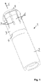
- Figure 1 shows a connecting plug 1 comprising a central pin 2 and a lamella sleeve 3.
- the lamella sleeve 3 is configured for being slid onto a front portion of the central pin 2, with the central pin 2 extending through the lamella sleeve 3.
- the lamella sleeve 3 circumferentially encloses an axial segment of the central pin 2.
- the lamella sleeve 3 is fixed to the central pin 2.
- the rear end of the lamella sleeve 3 is located at a predefined axial position 4.
- a plurality of lamellae 6 are disposed in the front portion of the lamella sleeve 3.
- Each of the lamellae 6 has a first end coupled to an annular carrier part of the lamella sleeve 3 and a second end that is implemented as a free end, with the free ends of the lamellae 6 facing towards the front end of the connecting plug 1.
- the lamellae 6 extend in an axial direction towards the front end of the connecting plug 1.
- Adjacent lamellae 6 are separated by slots 7 that extend in the axial direction of the lamella sleeve 3.
- the central pin 2 comprises a tip 8 that is located at the front end of the central pin 2, wherein the tip 8 extends beyond the front end of the lamella sleeve 3 in the mating direction 5.
- the connecting plug 1 is configured for being inserted into a corresponding socket (not shown) in the mating direction 5.
- the lamellae 6 are configured for being elastically deformed in a radially inwards direction and provide a reliable electrical contact with the inner surface of the corresponding socket.
- FIG 2 shows the assembly of the connecting plug 1.
- the lamella sleeve 3 comprises a rear opening 9 and a front opening 10. Viewed in the mating direction 5, the lamella sleeve 3 comprises an annular carrier part in the rear portion of the lamella sleeve 3 and a plurality of lamellae 6 arranged in the front portion of the lamella sleeve 3, the lamellae 6 being formed integrally with the annular carrier part, wherein the lamellae 6 extend predominantly in the mating direction 5.
- the central pin 2 is inserted into the rear opening 9 of the lamella sleeve 3 and the lamella sleeve 3 is pushed onto the central pin 2 and fixed to the central pin 2.
- the central pin extends through the rear opening 9, through the entire lamella sleeve 3 and through the front opening 10.
- the lamella sleeve 3 encloses an axial segment of the central pin 2.
- the central pin may extend through the rear opening and partly through the lamella sleeve, without extending through the front opening of the lamella sleeve.
- the lamella sleeve is fixed to the central pin and encloses an axial segment of the central pin.
- the central pin 2 comprises a circumferential recess 11.
- the central pin 2 may comprise a tapered portion. In this case, when the lamella sleeve 3 is pushed onto the tapered portion of the central pin 2, a press fit is established between the lamella sleeve 3 and the central pin 2.
- a plurality of other joining techniques such as for example flanging, crimping, clamping or beading may be used for forming a fixed connection between the central pin 2 and the lamella sleeve 3.
- the central pin 2 comprises a circumferential groove 12 disposed at the front portion of the central pin 2.
- the groove 12 is arranged such that a free space is provided behind the lamellae 6. Due to the presence of the groove 12, each of the lamellae 6 can be elastically deformed in a radially inwards direction.
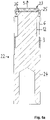
- Figure 3a shows a side view of the lamella sleeve 3.
- the lamella sleeve 3 comprises the rear opening 9, the front opening 10 and a plurality of lamellae 6.
- the lamellae 6 are disposed in the front portion of the lamella sleeve 3, with the free ends of the lamellae 6 facing towards the front end of the lamella sleeve 3.
- the slots 7 segment the front portion of the lamella sleeve 3 into the plurality of lamellae 6.
- each of the lamellae 6 comprises a bulge 13 disposed at the outer surface of the lamellae 6.
- the lamella sleeve 3 consists of conductive material, preferably of metal.
- the lamella sleeve 3 may for example be a rotationally symmetric part that is formed in one piece.
- the lamella sleeve 3 may for example be formed by deep drawing.
- Figure 3b shows a side view of the central pin 2.
- the central pin 2 comprises the tip 8, the groove 12 and the circumferential recess 11.
- the lamella sleeve 3 is pushed onto the central pin 2 until the lamella sleeve 3 abuts against the rear end of the circumferential recess 11, with the axial position 4 indicating the end position of the lamella sleeve's rear end.
- the central pin 2 consists of conductive material, preferably of metal.
- the central pin 2 is a solid part.
- the central pin 2 is a rotationally symmetric part.
- the central pin 2 is formed by turning.
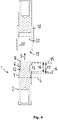
- Figure 4 shows a longitudinal section of the connecting plug 1 and a socket part 18.
- the lamella sleeve 3 is fixed to the central pin 2 and circumferentially encloses an axial segment of the central pin 2.
- the circumferential groove 12 provides a free space behind the front portion of the lamellae 6, such that the front portion of the lamellae 6 can be elastically deformed in a radially inwards direction of the lamella sleeve 3.
- the groove 12 is arranged such that the groove 12 overlaps with the front portion of the lamellae 6 when viewed in the mating direction 5.
- the groove 12 extends from the axial position 14 of the groove's rear end to the axial position 15 of the groove's front end, with the front end of the groove 12 being arranged such that the groove 12 extends beyond the free ends of the lamellae 6 when viewed in the mating direction 5.
- both the length 16 of the deformable portion of the lamellae 6 and the length 17 of the lamellae 6 are indicated.
- the rear end of the groove 12 serves as an abutting edge for the lamellae 6.
- the axial position 14 of the groove's rear end determines the length 16 of the deformable portion of the lamellae 6.
- the spring tension of the lamellae 6 can be varied. The longer the deformable portion is, the softer the spring tension of the lamellae 6 will be.
- the axial position 14 of the rear end of the groove 12 determines the spring tension of the lamellae 6. The spring tension determines the insertion force when inserting the connecting plug 1 into a corresponding socket.
- the depth of the groove 12 determines the maximum possible deflection of the lamellae 6 in a radially inwards direction.
- the bottom of the groove 12 serves as a supporting surface for the lamellae 6.
- the lamellae 6 are protected from being damaged, because when pushing the lamellae 6 in a radially inwards direction, the bottom of the groove 12 serves as a limit stop for the deformation of the lamellae, such that any plastic deformation of the lamellae 6 is prevented.
- the tip 8 may for example protrude from the bottom of the groove 12 in a radially outward direction in a way that the free ends of the lamellae 6 are protected. In particular, any plastic deformation of the lamellae 6 is prevented. For example, it is prevented that any item can be inserted in the interspace between the free ends of the lamellae 6 and the central pin 2.
- the plug-in connector shown in figure 4 further comprises a socket part 18 with an opening 19 configured for accommodating the connecting plug 1.
- the inner walls 20 of the socket part 18 may for example have an even surface.
- the bulges 13 of the lamellae are resiliently pressed against the inner walls 20 and thus, an electrical connection is established between the connecting plug 1 and the socket part 18.
- the socket part 18 may further comprise a circumferential groove 21 disposed in the interior of the socket part 18. In figure 4 , the circumferential groove 21 is indicated with dashed lines. If the connecting plug 1 is inserted into the opening 19 of the socket part 18, the bulges 13 of the lamellae 6 will engage with the circumferential groove 21.
- the bulges 13 are implemented as latching elements configured for latching with the circumferential groove 21, which serves as a counter-latching element.
- the interaction between the bulges 13 and the circumferential groove 21 determines the pulling force required for unplugging the connecting plug 1 from the socket part 18. Due to the latching mechanism, the mechanical stability of the plug-in connection can be improved.
- the connecting plug 22 comprises a lamella sleeve 3 with a plurality of lamellae 6, with the free ends of the lamellae 6 being oriented towards the front end of the connecting plug 22 when viewed in the mating direction 5.
- the lamella sleeve 3 is fixed to the central pin 23 and circumferentially encloses an axial segment of the central pin 23.
- the central pin 23 is not implemented in one piece.
- the central pin 23 comprises a contact pin 24 and an insulating cap 25 configured for covering the tip 26 of the contact pin 24.
- the central pin 23 extends through the rear opening 9, through the lamella sleeve 3 and through the front opening 10 of the lamella sleeve 3.
- the contact pin 24 consists of conductive material, preferably of metal. Further preferably, the contact pin 24 is formed as a turned part.
- the insulating cap 25 is made of insulating material, for example of plastic material, natural rubber or synthetic rubber. The insulating cap 25 may for example be formed by injection molding. The insulating cap 25 may be implemented as a snap-in member configured for being mounted on the tip 26 of the contact pin 24. The insulating cap 25 serves as a touch protection and prevents that a user may inadvertently touch life parts of the connecting plug 22.
- Figure 5b shows yet another example of a connecting plug 27.
- the central pin 28 is not implemented in one piece, but comprises two different components.
- the central pin 28 comprises a contact pin 29 and an insulating end part 30 disposed at the front end of the contact pin 29.
- the insulating end part 30 comprises a protruding member 31 that is inserted into the corresponding bore hole 32 of the contact pin 29.
- the central pin 28 extends through the rear opening 9, through the lamella sleeve 3 and through the front opening 10 of the lamella sleeve 3.
- the contact pin 29 consists of electrically conducting material, preferably of metal.
- the contact pin 29 may for example be a turned part.
- the insulating end part 30 is made of insulating material, for example of plastic material, natural rubber or synthetic rubber.
- the insulating end part 30 may for example be formed by injection molding.
- the insulating end part 30 serves as a touch protection.
- a variety of different joining techniques may be used, like for example screwing, caulking, establishing a press fit, etc.
- the insulating end part 30 may for example comprise one or more snap-in members configured for establishing a snap-fit with the contact pin 29.
- the lamella sleeve may as well be fixed inside a socket in accordance with an example not covered by the invention.
- the connecting plug may for example be a plain connector pin.
- a socket 33 comprising a socket element 34 and a lamella sleeve 35 disposed in the interior of the socket element 34 is shown.
- the lamella sleeve 35 comprises an annular carrier part and a plurality of lamellae 36, with each of the lamellae 36 having a first end coupled to the lamella sleeve's annular carrier part and a second end that is realised as a free end.
- the lamella sleeve's annular carrier part is located at a rear portion of the lamella sleeve 35 and the lamellae 36 are disposed at a front portion of the lamella sleeve 35, with the lamellae's free ends being oriented towards the front end of the socket 33.
- the lamella sleeve 35 comprises a plurality of slots 38 that extend from the lamella sleeve's front end in a predominantly axial direction and segment the front portion of the lamella sleeve 35 into a plurality of lamellae 36.
- the lamellae 36 are formed integrally with the annular carrier part.
- the lamellae 36 extend from the lamella sleeve's annular carrier part predominantly in the mating direction 37 of the socket 33.
- Each of the lamellae 36 may comprise one or more bulges 39 configured for being resiliently pressed in a radially inwards direction, in order to establish an electrical contact with a connector pin that is inserted into the socket 33.
- Each of the bulges 39 may stand out in a radially inwards direction.
- the lamella sleeve 35 consists of conductive material, preferably of metal.
- the lamella sleeve 35 may for example be a deep drawn part.
- the socket 33 further comprises the socket element 34 with an opening 40 configured for accommodating the rear part of the lamella sleeve 35.
- the socket element 34 further comprises a circumferential groove 41, with the inner diameter of the circumferential groove 41 being larger than the inner diameter of the opening 40.
- the circumferential groove 41 is configured for providing a free space behind the lamellae 36 of the lamella sleeve 35 such that the lamellae 36 can be resiliently deformed in a radially outwards direction.
- the socket element 34 comprises a front end part 42 that protrudes in a radially inwards direction.
- the front end part 42 at least partly covers the free ends of the lamellae 36, thus protecting the lamellae 36.
- the socket element 34 consists of conductive material, preferably of metal.
- the socket element 34 may for example be implemented as a turned part.
- FIG. 7 shows a longitudinal section of the socket 33 together with a connector pin 44.
- the socket 33 comprises a socket element 34 with an opening 40 configured for accommodating the lamella sleeve 35, with the lamellae 36 extending in the mating direction 37 towards the front end of the socket 33.
- the circumferential groove 41 extends from the opening 40 in a radially outwards direction.
- the circumferential groove 41 is disposed behind the deformable portion of the lamellae 36.
- the circumferential groove 41 is configured for providing a free space 43 behind the lamellae 36, the free space 43 being located radially outward of the lamellae 36.
- the circumferential groove 41 When viewed in the mating direction 37, the circumferential groove 41 extends beyond the front end of the lamellae 36 so that the circumferential groove 41 overlaps with the front portion of the lamellae 36. Due to the presence of the circumferential groove 41, the lamellae 36 can be resiliently deformed in a radially outward direction. When the lamellae 36 are resiliently deformed, they may enter the free space 43 provided by the circumferential groove 41. For example, in case a connector pin 44 is inserted into the socket 33, the lamellae 36 of the socket 33 will be deflected in a radially outward direction, with the bulges 39 being resiliently pressed against the outer surface of the connector pin 44.
- the depth of the circumferential groove 41 determines the maximum possible deflection of the lamellae 36 in a radially outward direction.
- the circumferential groove 41 serves as a limit stop configured for limiting the resilient deformation of the lamellae 36 in the radially outward direction.
- the circumferential groove 41 acts as a support for the lamellae 36 and prevents any plastic deformation of the lamellae 36.
- the rear end of the circumferential groove 41 serves as an abutting edge for the lamellae 36.
- the length 45 of the deformable portion of the lamellae 36 is determined by the axial position 46 of the rear end of the circumferential groove 41.
- the length 47 of the lamellae 36 is also indicated.
- the axial position 46 of the rear end of the groove 41 determines the spring tension of the lamellae 36. The longer the deformable portion of the lamellae 36 is, the softer the spring tension of the lamellae 36 will be. In contrast, by reducing the length 45 of the deformable portion, a comparatively hard spring tension of the lamellae 36 is obtained.
- the spring tension of the lamellae 36 can be set to a desired value. Thus, the insertion force for inserting the connector pin 44 into the socket 33 can be adjusted.
- the lamella sleeve 35 shown in figure 7 has both a front opening and a rear opening.
- a lamella sleeve with a closed base may be used as well.
Landscapes
- Engineering & Computer Science (AREA)
- Manufacturing & Machinery (AREA)
- Connector Housings Or Holding Contact Members (AREA)
- Details Of Connecting Devices For Male And Female Coupling (AREA)
- Manufacturing Of Electrical Connectors (AREA)
- Coupling Device And Connection With Printed Circuit (AREA)
Claims (11)
- Verbindungsstecker (1), umfassendeinen Mittelstift (2) undeine Lamellenhülse (3),wobei die Lamellenhülse (3) eine vordere Öffnung (10), eine hintere Öffnung (9), einen ringförmigen Trägerteil und eine Vielzahl von Lamellen (6) umfasst,wobei die Lamellenhülse (3) im Umfang ein axiales Segment des Mittelstifts (2) umschließt, wobei die Lamellenhülse (3) am Mittelstift (2) befestigt ist, wobei sich der Mittelstift (2) durch die hintere Öffnung (9) und wenigstens teilweise durch die Lamellenhülse (3) erstreckt, wobei in der Eingriffsrichtung (5) des Verbindungssteckers betrachtet der ringförmige Trägerteil in einem hinteren Abschnitt angeordnet ist und die Lamellen (6) in einem vorderen Abschnitt der Lamellenhülse (3) angeordnet sind, wobei jede der Lamellen (6) ein mit dem ringförmigen Trägerteil gekoppeltes erstes Ende und ein zweites Ende, das als ein freies Ende ausgeführt ist, aufweist, wobei die freien Enden der Lamellen (6) zu einem vorderen Ende des Verbindungssteckers (1) zeigen, und dadurch gekennzeichnet, dassder Mittelstift (2) eine Nut (12), eine Aussparung oder wenigstens eine Vertiefung aufweist, so dass ein freier Raum hinter den vorderen Abschnitten der Lamellen (6) angeordnet ist, wobei eine hintere Kante der Nut (12), der Aussparung oder der wenigstens einen Vertiefung als eine Stoßkante für die Lamellen (6) dient.
- Verbindungsstecker (1) nach Anspruch 1, wobei jede der Lamellen (6) in einer radial nach innen gerichteten Richtung der Lamellenhülse (3) elastisch verformbar ist.
- Verbindungsstecker (1) nach Anspruch 1 oder Anspruch 2, wobei sich der Mittelstift (2) durch die Lamellenhülse (3) und durch die vordere Öffnung (10) der Lamellenhülse (3) erstreckt.
- Verbindungsstecker (1) nach einem der Ansprüche 1 bis 3, wobei die Lamellenhülse (3) ein tiefgezogenes Teil ist.
- Verbindungsstecker (1) nach einem der Ansprüche 1 bis 4, wobei der Mittelstift (2) ein gedrehtes Teil ist.
- Verbindungsstecker (1) nach einem der Ansprüche 1 bis 5, wobei die Lamellenhülse (3) an den Mittelstift (2) geflanscht, gecrimpt, gebördelt, geklemmt oder aufgepresst ist.
- Verbindungsstecker (1) nach einem der Ansprüche 1 bis 6, wobei eine jeweilige Tiefe der Nut (12), der Aussparung oder der wenigstens einen Vertiefung eine maximale Durchbiegung der Lamellen (6) bestimmt.
- Verbindungsstecker (1) nach einem der Ansprüche 1 bis 7, wobei eine axiale Position (14) des hinteren Endes der Nut (12), der Aussparung oder der wenigstens einen Vertiefung in Bezug auf die Lamellenhülse (3) die Länge (16) der jeweiligen verformbaren Abschnitte der Lamellen (6) bestimmt.
- Verbindungsstecker (1) nach einem der Ansprüche 1 bis 8, wobei eine axiale Position (14) des hinteren Endes der Nut (12), der Aussparung oder der wenigstens einen Vertiefung in Bezug auf die Lamellenhülse (3) die Federspannung der Lamellen (6) bestimmt.
- Einsteck-Steckverbinder, umfassendeinen Verbindungsstecker (1) nach einem der Ansprüche 1 bis 9,eine entsprechende Buchse.
- Verbindungsbuchse (33), umfassend
eine Lamellenhülse (35), umfassend eine vordere Öffnung, einen ringförmigen Trägerteil und eine Vielzahl von Lamellen (36), wobei jede der Lamellen (36) ein erstes Ende, das integral mit dem ringförmigen Trägerteil gebildet ist, und ein zweites Ende, das als ein freies Ende ausgeführt ist, aufweist, ein Buchsenelement (34) mit einer zur Aufnahme von wenigstens einem hinteren Teil der Lamellenhülse (35) ausgebildeten Öffnung (40), wobei die Lamellenhülse (35) ein tiefgezogenes Teil ist, wobei das Buchsenelement (34) eine Aussparung oder eine Nut (41) oder wenigstens eine Vertiefung umfasst, die von der Öffnung (40) in einer radial nach außen gerichteten Richtung hervorragt, so dass ein freier Raum (43) in einer radial nach außen gerichteten Richtung hinter den vorderen Abschnitten der Lamellen (36) angeordnet ist, dadurch gekennzeichnet, dass eine hintere Kante der Nut (41), der Aussparung oder der wenigstens einen Vertiefung als eine Stoßkante für die Lamellen (36) dient.
Priority Applications (7)
| Application Number | Priority Date | Filing Date | Title |
|---|---|---|---|
| DK19183650.1T DK3761455T3 (da) | 2019-07-01 | 2019-07-01 | Tilslultningsstik med en midterstift og lamelbøsning og forbindelsesfatning med lamelbøsning |
| EP19183650.1A EP3761455B1 (de) | 2019-07-01 | 2019-07-01 | Verbindungsstecker mit zentralem stift und lamellenhülse und einer verbindungsbuchse mit lamellenhülse |
| KR1020200067446A KR102403318B1 (ko) | 2019-07-01 | 2020-06-04 | 연결플러그 및 그의 제조방법 및 연결플러그에 대응되는 소켓을 구성하는 플러그인 연결장치 및 라멜라슬리브를 갖는 연결소켓 |
| RU2020121096A RU2758795C1 (ru) | 2019-07-01 | 2020-06-25 | Соединительная вилка с центральным штырем и ламельной втулкой, способ формирования соединительной вилки и соединительной розетки с ламельной втулкой |
| US16/913,206 US11394147B2 (en) | 2019-07-01 | 2020-06-26 | Connecting plug with central pin and lamella sleeve, method for forming the connecting plug and connecting socket with lamella sleeve |
| JP2020111319A JP6997261B2 (ja) | 2019-07-01 | 2020-06-29 | 中心ピン及び薄板付きスリーブを有する接続プラグ、接続プラグを形成する方法、並びに薄板付きスリーブを有する接続ソケット |
| CN202010619401.0A CN112242625B (zh) | 2019-07-01 | 2020-06-30 | 连接插头及其形成方法、插入式连接器和连接插座 |
Applications Claiming Priority (1)
| Application Number | Priority Date | Filing Date | Title |
|---|---|---|---|
| EP19183650.1A EP3761455B1 (de) | 2019-07-01 | 2019-07-01 | Verbindungsstecker mit zentralem stift und lamellenhülse und einer verbindungsbuchse mit lamellenhülse |
Publications (2)
| Publication Number | Publication Date |
|---|---|
| EP3761455A1 EP3761455A1 (de) | 2021-01-06 |
| EP3761455B1 true EP3761455B1 (de) | 2022-06-22 |
Family
ID=67137845
Family Applications (1)
| Application Number | Title | Priority Date | Filing Date |
|---|---|---|---|
| EP19183650.1A Active EP3761455B1 (de) | 2019-07-01 | 2019-07-01 | Verbindungsstecker mit zentralem stift und lamellenhülse und einer verbindungsbuchse mit lamellenhülse |
Country Status (7)
| Country | Link |
|---|---|
| US (1) | US11394147B2 (de) |
| EP (1) | EP3761455B1 (de) |
| JP (1) | JP6997261B2 (de) |
| KR (1) | KR102403318B1 (de) |
| CN (1) | CN112242625B (de) |
| DK (1) | DK3761455T3 (de) |
| RU (1) | RU2758795C1 (de) |
Families Citing this family (26)
| Publication number | Priority date | Publication date | Assignee | Title |
|---|---|---|---|---|
| EP3815194B1 (de) * | 2018-06-29 | 2023-04-26 | Lisa Dräxlmaier GmbH | Hochstromkontakt zum kontaktieren einer hochstrombuchse |
| JP7066596B2 (ja) * | 2018-11-16 | 2022-05-13 | ホシデン株式会社 | コネクタ |
| JP7292190B2 (ja) * | 2019-11-29 | 2023-06-16 | ホシデン株式会社 | グランド端子及びこれを備えたコネクタ |
| TWM598550U (zh) * | 2020-03-05 | 2020-07-11 | 連展科技股份有限公司 | 具有冠簧之電源連接器 |
| DE102020108812A1 (de) * | 2020-03-31 | 2021-09-30 | Phoenix Contact E-Mobility Gmbh | Steckkontakt |
| DE102020112117A1 (de) * | 2020-05-05 | 2021-11-11 | Te Connectivity Germany Gmbh | Steckverbinder, Steckverbindergegenstück und Steckverbindersystem |
| EP3923421A1 (de) * | 2020-06-09 | 2021-12-15 | Afag Holding AG | Elektrische verbindungseinrichtung mit einem grundkörper und einem verschiebekörper |
| CN113036523B (zh) * | 2021-02-15 | 2023-02-28 | 中山得意电子有限公司 | 电连接器组合 |
| EP4080683A1 (de) * | 2021-04-20 | 2022-10-26 | Preci-Dip Sa | Anschlussstecker |
| CN113258372B (zh) | 2021-05-26 | 2022-12-02 | 宣城立讯精密工业有限公司 | 电性连接套件及电性连接器 |
| CN113258352B (zh) | 2021-05-26 | 2022-11-29 | 宣城立讯精密工业有限公司 | 电性连接套件及电连接器 |
| EP4099519B1 (de) * | 2021-06-01 | 2024-10-30 | Aptiv Technologies AG | Stecker- und buchsenstromanschlussanordnung, buchen- und steckerstromanschluss |
| DE102021206245A1 (de) | 2021-06-18 | 2022-12-22 | Robert Bosch Gesellschaft mit beschränkter Haftung | Verfahren zur Herstellung einer Steckverbindung sowie Steckverbindung |
| DE102021206246A1 (de) | 2021-06-18 | 2022-12-22 | Robert Bosch Gesellschaft mit beschränkter Haftung | Verfahren zur Herstellung einer Steckverbindung sowie Steckverbindung |
| DE102021206249A1 (de) | 2021-06-18 | 2022-12-22 | Robert Bosch Gesellschaft mit beschränkter Haftung | Verfahren und Vorrichtung zur Herstellung einer Steckverbindung, insbesondere einer Hochvolt-Steckverbindung |
| DE102021206248A1 (de) | 2021-06-18 | 2022-12-22 | Robert Bosch Gesellschaft mit beschränkter Haftung | Kontaktteil sowie Steckverbindung mit einem Kontaktteil |
| DE102021206250A1 (de) | 2021-06-18 | 2022-12-22 | Robert Bosch Gesellschaft mit beschränkter Haftung | Steckverbindung, insbesondere Hochvolt-Steckverbindung |
| DE102021206247A1 (de) | 2021-06-18 | 2022-12-22 | Robert Bosch Gesellschaft mit beschränkter Haftung | Kontaktteil sowie Steckverbindung mit einem Kontaktteil |
| EP4152526A1 (de) * | 2021-09-15 | 2023-03-22 | Avertronics Inc. | Leicht zu montierender verbinder |
| JP7697867B2 (ja) * | 2021-10-27 | 2025-06-24 | 矢崎総業株式会社 | シールド構造 |
| JP2023069862A (ja) * | 2021-11-08 | 2023-05-18 | 矢崎総業株式会社 | コネクタユニット |
| JP7348258B2 (ja) * | 2021-12-20 | 2023-09-20 | 日本航空電子工業株式会社 | 端子 |
| DE102022201373A1 (de) | 2022-02-10 | 2023-08-10 | Robert Bosch Gesellschaft mit beschränkter Haftung | Vorrichtung und Verfahren zur Herstellung einer elektrisch leitenden Steckverbindung |
| CN217505926U (zh) * | 2022-04-02 | 2022-09-27 | 宁德时代新能源科技股份有限公司 | 检测夹及检测组件 |
| EP4667045A1 (de) | 2024-06-18 | 2025-12-24 | ODU GmbH & Co KG. | Verbinder zum elektrischen verbinden einer implantierbaren leitungsvorrichtung |
| EP4668498A1 (de) | 2024-06-18 | 2025-12-24 | ODU GmbH & Co KG. | Schwimmender verbinder |
Family Cites Families (24)
| Publication number | Priority date | Publication date | Assignee | Title |
|---|---|---|---|---|
| CH112086A (de) | 1925-10-01 | 1925-10-01 | Co Delta | Elektrischer Kontaktstöpsel. |
| DE3608276A1 (de) * | 1986-03-12 | 1987-09-17 | Dunkel Otto Gmbh | Kontaktelement in form einer kontaktfederbuchse bzw. eines gefederten steckerstiftes und verfahren zu dessen herstellung |
| DE3808632C1 (de) | 1988-03-15 | 1989-10-12 | Georg Dr.-Ing. 8152 Feldkirchen-Westerham De Spinner | |
| JP2923518B2 (ja) * | 1994-03-18 | 1999-07-26 | 矢崎総業株式会社 | 大電流用端子及び加工方法 |
| DE29601407U1 (de) * | 1995-09-07 | 1996-05-23 | Oehlbach-Kabel GmbH, 76297 Stutensee | Koaxialstecker |
| US5667413A (en) | 1995-11-13 | 1997-09-16 | Alcoa Fujikura Ltd. | Socket-type electrical connector |
| CA2272458C (en) * | 1998-06-25 | 2008-03-18 | Leslie Laszlo Kerek | Hoodless electrical socket connector |
| DE19909107C2 (de) * | 1999-03-02 | 2002-06-20 | Tyco Electronics Logistics Ag | Außenleiterhülse mit Federkontakten |
| DE10041516B4 (de) * | 2000-08-24 | 2010-09-09 | Harting Electric Gmbh & Co. Kg | Elektrische Anschlußvorrichtung für hohe Ströme |
| DE102004002402B3 (de) | 2004-01-16 | 2005-11-03 | Tyco Electronics Amp Gmbh | Hochstrombelastbare Verbindungsvorrichtung sowie zugehöriges Kontaktierungselement |
| CN101103497A (zh) | 2005-01-13 | 2008-01-09 | 菲舍尔连接器控股股份有限公司 | 可锁定并能密封的连接器 |
| DE202005015800U1 (de) * | 2005-09-29 | 2005-12-08 | Büschel Verwaltungs GmbH | Stecker |
| ITVI20080006U1 (it) | 2008-02-28 | 2009-08-29 | Viemme Srl | Connessione elettrica perfezionata |
| DE102009035716B4 (de) * | 2009-07-31 | 2014-03-27 | Wago Verwaltungsgesellschaft Mbh | Steckverbinder |
| CN201898221U (zh) | 2010-09-01 | 2011-07-13 | 沈阳兴华航空电器有限责任公司 | 一种电连接器用簧片式插孔 |
| US9356374B2 (en) * | 2013-01-09 | 2016-05-31 | Amphenol Corporation | Float adapter for electrical connector |
| CN203503846U (zh) | 2013-08-23 | 2014-03-26 | 沈阳兴华航空电器有限责任公司 | 一种鼓簧式弹性可靠接触件 |
| CN104852183B (zh) | 2015-03-26 | 2017-01-25 | 常熟市福莱德连接器科技有限公司 | 一种光伏连接器 |
| WO2017144069A1 (de) | 2016-02-26 | 2017-08-31 | Rosenberger Hochfrequenztechnik Gmbh & Co. Kg | Kontakthülse für einen elektrischen steckverbinder |
| JP6812923B2 (ja) * | 2017-07-27 | 2021-01-13 | 住友電装株式会社 | 端子金具 |
| CN207426271U (zh) | 2017-09-20 | 2018-05-29 | 上海航天科工电器研究院有限公司 | 一种装有接触元件的射频同轴电连接器 |
| JP6909698B2 (ja) * | 2017-10-05 | 2021-07-28 | 株式会社ヨコオ | スプリングコネクタ |
| CN207947409U (zh) | 2018-02-27 | 2018-10-09 | 珠海优特电力科技股份有限公司 | 导电电极及具有其的锁具 |
| EP3641068B1 (de) * | 2018-10-16 | 2021-01-27 | ODU GmbH & Co. KG | Verbindungsstecker und -dose mit lamellenkorb |
-
2019
- 2019-07-01 EP EP19183650.1A patent/EP3761455B1/de active Active
- 2019-07-01 DK DK19183650.1T patent/DK3761455T3/da active
-
2020
- 2020-06-04 KR KR1020200067446A patent/KR102403318B1/ko not_active Expired - Fee Related
- 2020-06-25 RU RU2020121096A patent/RU2758795C1/ru active
- 2020-06-26 US US16/913,206 patent/US11394147B2/en active Active
- 2020-06-29 JP JP2020111319A patent/JP6997261B2/ja active Active
- 2020-06-30 CN CN202010619401.0A patent/CN112242625B/zh not_active Expired - Fee Related
Also Published As
| Publication number | Publication date |
|---|---|
| CN112242625B (zh) | 2022-02-11 |
| US20210005995A1 (en) | 2021-01-07 |
| DK3761455T3 (da) | 2022-08-29 |
| KR102403318B1 (ko) | 2022-05-30 |
| RU2758795C1 (ru) | 2021-11-01 |
| JP2021009841A (ja) | 2021-01-28 |
| CN112242625A (zh) | 2021-01-19 |
| EP3761455A1 (de) | 2021-01-06 |
| KR20210003665A (ko) | 2021-01-12 |
| US11394147B2 (en) | 2022-07-19 |
| JP6997261B2 (ja) | 2022-01-17 |
Similar Documents
| Publication | Publication Date | Title |
|---|---|---|
| EP3761455B1 (de) | Verbindungsstecker mit zentralem stift und lamellenhülse und einer verbindungsbuchse mit lamellenhülse | |
| US11101589B2 (en) | Connecting plug and socket with lamella basket | |
| EP3584889B1 (de) | Verbindervorrichtung | |
| KR101031118B1 (ko) | 동축 커넥터 | |
| EP1686660B1 (de) | Gegenüber der Umgebung abgedichteter selbstzentrierender Verbinder | |
| US4550972A (en) | Cylindrical socket contact | |
| US9515403B2 (en) | Female terminal assembly | |
| CN107154545B (zh) | 具有低轮廓帽的圆形端子 | |
| EP2369689B1 (de) | Elektrischer Steckverbinder | |
| CN214957444U (zh) | 具有冠簧之电源连接器 | |
| US11211732B2 (en) | Plug-in connector part with caulked contact elements and method for producing said plug-in connector part | |
| CN113258377A (zh) | 用于大电流插入式连接的屏蔽弹簧壳 | |
| CN111755870B (zh) | 电端子、电连接器组件及其形成方法 | |
| CN112217016B (zh) | 电连接器 | |
| JPH0641082U (ja) | 同軸コネクタ | |
| JP2010113962A (ja) | ソケット端子 | |
| EP3826117B1 (de) | Austauschkontaktspitze für einen elektrischen kontakt eines steckverbinders | |
| EP0123096A1 (de) | Aus zwei Teilen zusammengesetzte elektrische Sockelkontaktanordnung | |
| CN114122788A (zh) | 一种具有多挡位锁定功能连接器 | |
| CN222365757U (zh) | 复合型大电流母端子以及连接器 | |
| JP2026000234A (ja) | コネクタ | |
| JP2016024894A (ja) | 端子 |
Legal Events
| Date | Code | Title | Description |
|---|---|---|---|
| PUAI | Public reference made under article 153(3) epc to a published international application that has entered the european phase |
Free format text: ORIGINAL CODE: 0009012 |
|
| STAA | Information on the status of an ep patent application or granted ep patent |
Free format text: STATUS: THE APPLICATION HAS BEEN PUBLISHED |
|
| AK | Designated contracting states |
Kind code of ref document: A1 Designated state(s): AL AT BE BG CH CY CZ DE DK EE ES FI FR GB GR HR HU IE IS IT LI LT LU LV MC MK MT NL NO PL PT RO RS SE SI SK SM TR |
|
| AX | Request for extension of the european patent |
Extension state: BA ME |
|
| STAA | Information on the status of an ep patent application or granted ep patent |
Free format text: STATUS: REQUEST FOR EXAMINATION WAS MADE |
|
| 17P | Request for examination filed |
Effective date: 20210316 |
|
| RBV | Designated contracting states (corrected) |
Designated state(s): AL AT BE BG CH CY CZ DE DK EE ES FI FR GB GR HR HU IE IS IT LI LT LU LV MC MK MT NL NO PL PT RO RS SE SI SK SM TR |
|
| RAP3 | Party data changed (applicant data changed or rights of an application transferred) |
Owner name: ODU GMBH & CO. KG |
|
| GRAP | Despatch of communication of intention to grant a patent |
Free format text: ORIGINAL CODE: EPIDOSNIGR1 |
|
| STAA | Information on the status of an ep patent application or granted ep patent |
Free format text: STATUS: GRANT OF PATENT IS INTENDED |
|
| INTG | Intention to grant announced |
Effective date: 20220210 |
|
| GRAS | Grant fee paid |
Free format text: ORIGINAL CODE: EPIDOSNIGR3 |
|
| GRAA | (expected) grant |
Free format text: ORIGINAL CODE: 0009210 |
|
| STAA | Information on the status of an ep patent application or granted ep patent |
Free format text: STATUS: THE PATENT HAS BEEN GRANTED |
|
| AK | Designated contracting states |
Kind code of ref document: B1 Designated state(s): AL AT BE BG CH CY CZ DE DK EE ES FI FR GB GR HR HU IE IS IT LI LT LU LV MC MK MT NL NO PL PT RO RS SE SI SK SM TR |
|
| REG | Reference to a national code |
Ref country code: GB Ref legal event code: FG4D |
|
| REG | Reference to a national code |
Ref country code: CH Ref legal event code: EP |
|
| REG | Reference to a national code |
Ref country code: DE Ref legal event code: R096 Ref document number: 602019016071 Country of ref document: DE |
|
| REG | Reference to a national code |
Ref country code: AT Ref legal event code: REF Ref document number: 1500396 Country of ref document: AT Kind code of ref document: T Effective date: 20220715 |
|
| REG | Reference to a national code |
Ref country code: IE Ref legal event code: FG4D |
|
| REG | Reference to a national code |
Ref country code: SE Ref legal event code: TRGR |
|
| REG | Reference to a national code |
Ref country code: DK Ref legal event code: T3 Effective date: 20220823 |
|
| REG | Reference to a national code |
Ref country code: LT Ref legal event code: MG9D |
|
| REG | Reference to a national code |
Ref country code: NL Ref legal event code: MP Effective date: 20220622 |
|
| PG25 | Lapsed in a contracting state [announced via postgrant information from national office to epo] |
Ref country code: NO Free format text: LAPSE BECAUSE OF FAILURE TO SUBMIT A TRANSLATION OF THE DESCRIPTION OR TO PAY THE FEE WITHIN THE PRESCRIBED TIME-LIMIT Effective date: 20220922 Ref country code: LT Free format text: LAPSE BECAUSE OF FAILURE TO SUBMIT A TRANSLATION OF THE DESCRIPTION OR TO PAY THE FEE WITHIN THE PRESCRIBED TIME-LIMIT Effective date: 20220622 Ref country code: HR Free format text: LAPSE BECAUSE OF FAILURE TO SUBMIT A TRANSLATION OF THE DESCRIPTION OR TO PAY THE FEE WITHIN THE PRESCRIBED TIME-LIMIT Effective date: 20220622 Ref country code: GR Free format text: LAPSE BECAUSE OF FAILURE TO SUBMIT A TRANSLATION OF THE DESCRIPTION OR TO PAY THE FEE WITHIN THE PRESCRIBED TIME-LIMIT Effective date: 20220923 Ref country code: FI Free format text: LAPSE BECAUSE OF FAILURE TO SUBMIT A TRANSLATION OF THE DESCRIPTION OR TO PAY THE FEE WITHIN THE PRESCRIBED TIME-LIMIT Effective date: 20220622 Ref country code: BG Free format text: LAPSE BECAUSE OF FAILURE TO SUBMIT A TRANSLATION OF THE DESCRIPTION OR TO PAY THE FEE WITHIN THE PRESCRIBED TIME-LIMIT Effective date: 20220922 |
|
| REG | Reference to a national code |
Ref country code: AT Ref legal event code: MK05 Ref document number: 1500396 Country of ref document: AT Kind code of ref document: T Effective date: 20220622 |
|
| PG25 | Lapsed in a contracting state [announced via postgrant information from national office to epo] |
Ref country code: RS Free format text: LAPSE BECAUSE OF FAILURE TO SUBMIT A TRANSLATION OF THE DESCRIPTION OR TO PAY THE FEE WITHIN THE PRESCRIBED TIME-LIMIT Effective date: 20220622 Ref country code: LV Free format text: LAPSE BECAUSE OF FAILURE TO SUBMIT A TRANSLATION OF THE DESCRIPTION OR TO PAY THE FEE WITHIN THE PRESCRIBED TIME-LIMIT Effective date: 20220622 |
|
| PG25 | Lapsed in a contracting state [announced via postgrant information from national office to epo] |
Ref country code: NL Free format text: LAPSE BECAUSE OF FAILURE TO SUBMIT A TRANSLATION OF THE DESCRIPTION OR TO PAY THE FEE WITHIN THE PRESCRIBED TIME-LIMIT Effective date: 20220622 |
|
| PG25 | Lapsed in a contracting state [announced via postgrant information from national office to epo] |
Ref country code: SM Free format text: LAPSE BECAUSE OF FAILURE TO SUBMIT A TRANSLATION OF THE DESCRIPTION OR TO PAY THE FEE WITHIN THE PRESCRIBED TIME-LIMIT Effective date: 20220622 Ref country code: SK Free format text: LAPSE BECAUSE OF FAILURE TO SUBMIT A TRANSLATION OF THE DESCRIPTION OR TO PAY THE FEE WITHIN THE PRESCRIBED TIME-LIMIT Effective date: 20220622 Ref country code: RO Free format text: LAPSE BECAUSE OF FAILURE TO SUBMIT A TRANSLATION OF THE DESCRIPTION OR TO PAY THE FEE WITHIN THE PRESCRIBED TIME-LIMIT Effective date: 20220622 Ref country code: PT Free format text: LAPSE BECAUSE OF FAILURE TO SUBMIT A TRANSLATION OF THE DESCRIPTION OR TO PAY THE FEE WITHIN THE PRESCRIBED TIME-LIMIT Effective date: 20221024 Ref country code: ES Free format text: LAPSE BECAUSE OF FAILURE TO SUBMIT A TRANSLATION OF THE DESCRIPTION OR TO PAY THE FEE WITHIN THE PRESCRIBED TIME-LIMIT Effective date: 20220622 Ref country code: EE Free format text: LAPSE BECAUSE OF FAILURE TO SUBMIT A TRANSLATION OF THE DESCRIPTION OR TO PAY THE FEE WITHIN THE PRESCRIBED TIME-LIMIT Effective date: 20220622 Ref country code: CZ Free format text: LAPSE BECAUSE OF FAILURE TO SUBMIT A TRANSLATION OF THE DESCRIPTION OR TO PAY THE FEE WITHIN THE PRESCRIBED TIME-LIMIT Effective date: 20220622 Ref country code: AT Free format text: LAPSE BECAUSE OF FAILURE TO SUBMIT A TRANSLATION OF THE DESCRIPTION OR TO PAY THE FEE WITHIN THE PRESCRIBED TIME-LIMIT Effective date: 20220622 |
|
| PG25 | Lapsed in a contracting state [announced via postgrant information from national office to epo] |
Ref country code: PL Free format text: LAPSE BECAUSE OF FAILURE TO SUBMIT A TRANSLATION OF THE DESCRIPTION OR TO PAY THE FEE WITHIN THE PRESCRIBED TIME-LIMIT Effective date: 20220622 Ref country code: IS Free format text: LAPSE BECAUSE OF FAILURE TO SUBMIT A TRANSLATION OF THE DESCRIPTION OR TO PAY THE FEE WITHIN THE PRESCRIBED TIME-LIMIT Effective date: 20221022 |
|
| REG | Reference to a national code |
Ref country code: CH Ref legal event code: PL |
|
| REG | Reference to a national code |
Ref country code: DE Ref legal event code: R097 Ref document number: 602019016071 Country of ref document: DE |
|
| REG | Reference to a national code |
Ref country code: BE Ref legal event code: MM Effective date: 20220731 |
|
| PG25 | Lapsed in a contracting state [announced via postgrant information from national office to epo] |
Ref country code: MC Free format text: LAPSE BECAUSE OF FAILURE TO SUBMIT A TRANSLATION OF THE DESCRIPTION OR TO PAY THE FEE WITHIN THE PRESCRIBED TIME-LIMIT Effective date: 20220622 Ref country code: AL Free format text: LAPSE BECAUSE OF FAILURE TO SUBMIT A TRANSLATION OF THE DESCRIPTION OR TO PAY THE FEE WITHIN THE PRESCRIBED TIME-LIMIT Effective date: 20220622 |
|
| PG25 | Lapsed in a contracting state [announced via postgrant information from national office to epo] |
Ref country code: LU Free format text: LAPSE BECAUSE OF NON-PAYMENT OF DUE FEES Effective date: 20220701 Ref country code: LI Free format text: LAPSE BECAUSE OF NON-PAYMENT OF DUE FEES Effective date: 20220731 Ref country code: CH Free format text: LAPSE BECAUSE OF NON-PAYMENT OF DUE FEES Effective date: 20220731 |
|
| PLBE | No opposition filed within time limit |
Free format text: ORIGINAL CODE: 0009261 |
|
| STAA | Information on the status of an ep patent application or granted ep patent |
Free format text: STATUS: NO OPPOSITION FILED WITHIN TIME LIMIT |
|
| 26N | No opposition filed |
Effective date: 20230323 |
|
| PG25 | Lapsed in a contracting state [announced via postgrant information from national office to epo] |
Ref country code: BE Free format text: LAPSE BECAUSE OF NON-PAYMENT OF DUE FEES Effective date: 20220731 |
|
| PG25 | Lapsed in a contracting state [announced via postgrant information from national office to epo] |
Ref country code: IE Free format text: LAPSE BECAUSE OF NON-PAYMENT OF DUE FEES Effective date: 20220701 |
|
| PG25 | Lapsed in a contracting state [announced via postgrant information from national office to epo] |
Ref country code: SI Free format text: LAPSE BECAUSE OF FAILURE TO SUBMIT A TRANSLATION OF THE DESCRIPTION OR TO PAY THE FEE WITHIN THE PRESCRIBED TIME-LIMIT Effective date: 20220622 |
|
| PGFP | Annual fee paid to national office [announced via postgrant information from national office to epo] |
Ref country code: SE Payment date: 20230724 Year of fee payment: 5 Ref country code: DK Payment date: 20230724 Year of fee payment: 5 |
|
| PG25 | Lapsed in a contracting state [announced via postgrant information from national office to epo] |
Ref country code: MK Free format text: LAPSE BECAUSE OF FAILURE TO SUBMIT A TRANSLATION OF THE DESCRIPTION OR TO PAY THE FEE WITHIN THE PRESCRIBED TIME-LIMIT Effective date: 20220622 Ref country code: CY Free format text: LAPSE BECAUSE OF FAILURE TO SUBMIT A TRANSLATION OF THE DESCRIPTION OR TO PAY THE FEE WITHIN THE PRESCRIBED TIME-LIMIT Effective date: 20220622 |
|
| PG25 | Lapsed in a contracting state [announced via postgrant information from national office to epo] |
Ref country code: HU Free format text: LAPSE BECAUSE OF FAILURE TO SUBMIT A TRANSLATION OF THE DESCRIPTION OR TO PAY THE FEE WITHIN THE PRESCRIBED TIME-LIMIT; INVALID AB INITIO Effective date: 20190701 |
|
| PG25 | Lapsed in a contracting state [announced via postgrant information from national office to epo] |
Ref country code: TR Free format text: LAPSE BECAUSE OF FAILURE TO SUBMIT A TRANSLATION OF THE DESCRIPTION OR TO PAY THE FEE WITHIN THE PRESCRIBED TIME-LIMIT Effective date: 20220622 |
|
| PG25 | Lapsed in a contracting state [announced via postgrant information from national office to epo] |
Ref country code: MT Free format text: LAPSE BECAUSE OF FAILURE TO SUBMIT A TRANSLATION OF THE DESCRIPTION OR TO PAY THE FEE WITHIN THE PRESCRIBED TIME-LIMIT Effective date: 20220622 |
|
| PGFP | Annual fee paid to national office [announced via postgrant information from national office to epo] |
Ref country code: GB Payment date: 20240723 Year of fee payment: 6 |
|
| PGFP | Annual fee paid to national office [announced via postgrant information from national office to epo] |
Ref country code: IT Payment date: 20240731 Year of fee payment: 6 |
|
| PG25 | Lapsed in a contracting state [announced via postgrant information from national office to epo] |
Ref country code: BG Free format text: LAPSE BECAUSE OF FAILURE TO SUBMIT A TRANSLATION OF THE DESCRIPTION OR TO PAY THE FEE WITHIN THE PRESCRIBED TIME-LIMIT Effective date: 20220622 |
|
| PG25 | Lapsed in a contracting state [announced via postgrant information from national office to epo] |
Ref country code: BG Free format text: LAPSE BECAUSE OF FAILURE TO SUBMIT A TRANSLATION OF THE DESCRIPTION OR TO PAY THE FEE WITHIN THE PRESCRIBED TIME-LIMIT Effective date: 20220622 |
|
| REG | Reference to a national code |
Ref country code: DK Ref legal event code: EBP Effective date: 20240731 |
|
| REG | Reference to a national code |
Ref country code: SE Ref legal event code: EUG |
|
| PG25 | Lapsed in a contracting state [announced via postgrant information from national office to epo] |
Ref country code: DK Free format text: LAPSE BECAUSE OF NON-PAYMENT OF DUE FEES Effective date: 20240731 |
|
| PGFP | Annual fee paid to national office [announced via postgrant information from national office to epo] |
Ref country code: DE Payment date: 20250722 Year of fee payment: 7 |
|
| PG25 | Lapsed in a contracting state [announced via postgrant information from national office to epo] |
Ref country code: SE Free format text: LAPSE BECAUSE OF NON-PAYMENT OF DUE FEES Effective date: 20240702 |
|
| PGFP | Annual fee paid to national office [announced via postgrant information from national office to epo] |
Ref country code: FR Payment date: 20250723 Year of fee payment: 7 |
|
| GBPC | Gb: european patent ceased through non-payment of renewal fee |
Effective date: 20250701 |
|
| PG25 | Lapsed in a contracting state [announced via postgrant information from national office to epo] |
Ref country code: GB Free format text: LAPSE BECAUSE OF NON-PAYMENT OF DUE FEES Effective date: 20250701 |