EP3761490B1 - Procédé de positionnement de segment de bobine, outil de positionnement de segment de bobine, et dispositif de positionnement de segment de bobine - Google Patents
Procédé de positionnement de segment de bobine, outil de positionnement de segment de bobine, et dispositif de positionnement de segment de bobine Download PDFInfo
- Publication number
- EP3761490B1 EP3761490B1 EP19770309.3A EP19770309A EP3761490B1 EP 3761490 B1 EP3761490 B1 EP 3761490B1 EP 19770309 A EP19770309 A EP 19770309A EP 3761490 B1 EP3761490 B1 EP 3761490B1
- Authority
- EP
- European Patent Office
- Prior art keywords
- insertion holes
- distal end
- core
- end portions
- pairs
- Prior art date
- Legal status (The legal status is an assumption and is not a legal conclusion. Google has not performed a legal analysis and makes no representation as to the accuracy of the status listed.)
- Active
Links
Images


Classifications
-
- H—ELECTRICITY
- H02—GENERATION; CONVERSION OR DISTRIBUTION OF ELECTRIC POWER
- H02K—DYNAMO-ELECTRIC MACHINES
- H02K15/00—Processes or apparatus specially adapted for manufacturing, assembling, maintaining or repairing of dynamo-electric machines
- H02K15/06—Embedding prefabricated windings in the machines
- H02K15/062—Windings in slots; Salient pole windings
-
- H—ELECTRICITY
- H02—GENERATION; CONVERSION OR DISTRIBUTION OF ELECTRIC POWER
- H02K—DYNAMO-ELECTRIC MACHINES
- H02K15/00—Processes or apparatus specially adapted for manufacturing, assembling, maintaining or repairing of dynamo-electric machines
- H02K15/30—Manufacture of winding connections
- H02K15/33—Connecting winding sections; Forming leads; Connecting leads to terminals
- H02K15/35—Form-wound windings
- H02K15/36—Processes or apparatus for simultaneously twisting two or more open ends of hairpins after their insertion into the machine
-
- H—ELECTRICITY
- H02—GENERATION; CONVERSION OR DISTRIBUTION OF ELECTRIC POWER
- H02K—DYNAMO-ELECTRIC MACHINES
- H02K3/00—Details of windings
- H02K3/04—Windings characterised by the conductor shape, form or construction, e.g. with bar conductors
-
- Y—GENERAL TAGGING OF NEW TECHNOLOGICAL DEVELOPMENTS; GENERAL TAGGING OF CROSS-SECTIONAL TECHNOLOGIES SPANNING OVER SEVERAL SECTIONS OF THE IPC; TECHNICAL SUBJECTS COVERED BY FORMER USPC CROSS-REFERENCE ART COLLECTIONS [XRACs] AND DIGESTS
- Y10—TECHNICAL SUBJECTS COVERED BY FORMER USPC
- Y10T—TECHNICAL SUBJECTS COVERED BY FORMER US CLASSIFICATION
- Y10T29/00—Metal working
- Y10T29/49—Method of mechanical manufacture
- Y10T29/49002—Electrical device making
- Y10T29/49009—Dynamoelectric machine
Definitions
- the present invention relates to a coil segment positioning method for positioning distal end portions of coil segments constituting a coil used in an electrical rotating machine such as a motor or a generator, or in an electromagnetic machine such as a transformer, and to a coil segment positioning tool and a coil segment positioning apparatus.
- a coil with a plurality of coil segments connected one another in series is formed by: inserting the coil segments, each formed by bending a rectangular flat wire into a U-shape, into slots of the core; twisting layers, neighboring in the radial direction of the core, of distal end potions in the insertion direction of the coil segments that are protruding from an end face of the core, in opposite directions along the circumferential direction; and electrically connecting the distal end potions facing each other in the radial direction.
- the distal end portions in the insertion direction of the coil segments, that are free end sides, are formed to be peeled-off portions in which an insulating film made of enamel, polyimide resin, or the like is peeled-off in advance, and the peeled-off portions are joined with each other by arc welding, laser welding, or the like in a state where the peeled-off portions are in contact with each other in the radial direction of the core.
- Coil segments constituting this type of coils include ordinary coil segments that are merely units of constitution of the coils, and coil segments for leads to be electrically connected to a power supply terminal, an output terminal, or a common conductor.
- An ordinary coil segment has a pair of slot insertion portions (straight portions) of the same length in the U-shape, and a coil segment for a lead is, for example, a variant segment in which only one of the slot insertion portions thereof is long.
- the ordinary coil segments are referred to as ordinary segments, and the coil segments for leads are referred to as variant segments.
- a pair of distal end portions of a coil segment protruding from an end face of the core are located in layers adjacent to each other in the radial direction of the core, and bent diagonally in opposite directions along the circumferential direction of the core, respectively (twist processing).
- the peeled-off portions are kept in linear shapes along the axial direction of the core.
- so-called layer transfer can be made by connecting a coil segment at the end of the first turn with a coil segment at the beginning of the second turn. By repeating this connection, it is possible to form a coil in which annular arrangements of the coil segments are connected in series, wound on the core by a plurality of turns.
- misalignment along the circumferential direction of the core between the peeled-off portions facing each other is corrected (alignment), and misalignment therebetween along the radial direction of the core is corrected (butting).
- PTL1 proposes a segment positioning apparatus that uses two annular plates each having insertion windows each configured to accept insertion of a segment end pair (a pair of peeled-off portions) facing each other, and performs positioning of a plurality of segment end pairs along the circumferential direction and the radial direction of the core at once by rotating the respective plates in opposite directions to constrain the segment end pairs.
- the insertion windows of each of the plates have an opening in a shape corresponding to the shape of the slots, and the insertion windows are arranged in the number corresponding to the number of the slots. Accordingly, a segment end pair group constituted by the number of end portions of the segments arranged in one slot is inserted into one insertion window.
- edges of the insertion windows of the plates configured to approach each other when the plates are rotated are formed with projections at opposite positions thereof, and the segment end pairs are sandwiched and restrained in regions partitioned by overlaps between the projections, thereby the positioning is performed.
- EP 2 684 283 A1 discloses an apparatus and a method for aligning wire conductors extending from coil members inserted in slots of a core of an electric dynamo machine to join the ends of the wire conductors by means of a welding operation.
- a first member having a plurality of passages and a second member having a plurality of passages are assembled adjacent to each other to align in pairs the passages of the first member with the passages of the second member.
- Each pair of aligned passages forms a single passage capable of receiving at least the end portions of two conductors, wherein the first member and the second member are relatively moved in the circumferential direction of the core to cause the sides of the passages to engage and move the end portions of the wire conductors in the circumferential direction.
- a positioning and clamping apparatus for positioning and clamping one or more wire ends for the purpose of further processing during the course of producing the machine element of the electrical machine- the apparatus comprises a capturing device for capturing and positioning the at least one wire end, wherein the capturing device has at least one oblique guide for relatively positioning the at least one wire end.
- WO 2017/159864 A1 discloses a method for manufacturing a stator, wherein clamping is performed before welding an end portion of a coil segment inserted in a stator core.
- a locator-equipped clamp jig is used that is capable of suppressing interference between base sections of segments when clamped by the clamp jig.
- the locator-equipped clamp jig has a locator that is provided to part of a main clamp body on a stator core side and has a plurality of protrusions arranged on an upper surface of an electrical conductor that is adjacent, in the radial direction of the stator core, to an electrical conductor being clamped by the main clamp body, wherein the width of the protrusions in the radial direction of the stator core is at least the width of one of the electrical conductors.
- JP 2015-171260 A aims at performing a positioning of rows of end parts of conductor segments by holding the rows of the end parts between both sides thereof even though positions of the respective rows of the end parts of the conductor segments are varied to a certain extent.
- a positioning member comprises an opening part into which the rows of the end parts can be inserted, a first positioning part that is provided on an inner edge of the opening part and comes in contact with one side in a circumference direction of an annular core with respect to a first end part row and a second positioning part that is provided on an outer edge of the positioning member and comes in contact with one side in the circumference direction of the annular core with respect to a second row of the end parts different from the first row of the end parts.
- each insertion window is opened as a single hole configured to accept insertion of all the end portions of the segments disposed in one slot, even if there is some variability among positions of some segment end pair facing each other in the radial direction of the core after the twisting process, it is possible to insert the segment end pair group to be inserted.
- each segment end pair when inserted in a state where there is some variability among the positions of the segment end pairs , each segment end pair will not always be accurately positioned into the region partitioned by the projections, and actually it is often a problem that the projections intrude into a segment end pair to be welded with each other and accordingly the end portions of the pair are separated.
- the positioning operation is performed in accordance with the regions partitioned by the projections, the operation is further limited, which deteriorates the complexity and troublesomeness.
- the present invention has been developed in view of the above situation, and it is an object of the present invention to improve working efficiency of positioning of distal end portions of coil segments and to improve strength of a member for the positioning.
- a rough positional adjustment is performed in a state where the positional adjustment of distal end pairs constituted by a pair of distal end portions facing each other in the radial direction of the core can be easily performed, and by utilizing the aligned property, the positions of the distal end portions constituting each distal end pair are aligned using a member having insertion holes each configured to separately accept insertion of each distal end pair, thereby achieving both of improvement of the working efficiency of the positioning and improvement of the strength of the positioning member.
- a positioning apparatus and a positioning tool according to an embodiment of the present invention will be described.
- the positioning apparatus 2 has: the positioning tool 4; a base member 10 for rotatably supporting a first plate 6 and a second plate 8 of the positioning tool 4; a first operable member 12 for rotating the first plate 6; a second operable member 14 for rotating the second plate 8; and a drive mechanism configured to rotate the first operable member 12 and the second operable member 14 in different directions by moving the first operable member 12 and the second operable member 14 closer to each other or away from each other.
- the positioning apparatus 2 and the positioning tool 4 are embodiments of the positioning apparatus and the positioning tool of the present invention, respectively.
- the first plate 6 and the second plate 8 are examples of the first member and the second member, respectively.
- a stator core 18 that is an example of a workpiece is supported such that distal end pairs 22 of coil segments protruding from an end face of a core 20 are positioned upward.
- the base member 10 has: a cylindrical base body 24 configured to support the lower end of the core 20 by a mounting surface 24a; a flange 26 fixed to the upper surface of the base body 24; a support ring 28 supporting the positioning tool 4; and a plurality of props 30 disposed between the flange 26 and the support ring 28 at intervals in the circumferential direction of the core 20.
- the first plate 6 has an inner side ring 32 and an annular plate body 36 fixed to the upper surface of the inner side ring 32 by screws 34.
- the second plate 8 has an outer side ring 38 and an annular plate body 42 fixed to the upper surface of the outer side ring 38 by screws 40.
- a pedestal ring 44 for supporting the lower end of the inner side ring 32 is fixed by screws 46.
- the pedestal ring 44 is supported by the stepped surface of the support ring 28 of the base member 10, and thereby each of the first plate 6 and the second plate 8 is supported rotatably with respect to the base member 10.
- the first operable member 12 is formed in an L-shape including a fixing piece 12a extending in the circumferential direction of the core 20, and an operation piece 12b extending in the radial direction of the core 20.
- the fixing piece 12a is fixed to the inner side ring 32 shown in Fig. 1 by two screws 50.
- the second operable member 14 is similarly formed in an L-shape including a fixing piece 14a extending in the circumferential direction of the core 20, and an operation piece 14b extending in the radial direction of the core 20.
- the fixing piece 14a is fixed to the outer side ring 38 shown in Fig. 1 by two screws 50.
- the drive mechanism 16 has: a drive piece 52 fixed to the operation piece 12b of the first operable member 12; a drive piece 54 fixed to the operation piece 14b of the second operable member 14; and a drive screw 56 constituted by a long bolt screwed to the drive piece 52 through the drive piece 54.
- a spacing member 58 fixed to the support ring 28 shown in Fig. 1 is disposed between the drive piece 52 and the drive piece 54.
- the position where the drive piece 52 and the drive piece 54 are in contact with the spacing member 58 is a position for the positioning by the positioning tool 4.
- the plate body 36 of the first plate 6 rotates in one direction (R1 direction) along the circumferential direction of the core 20, and the plate body 42 of the second plate 8 rotates in the opposite direction (R2 direction), simultaneously.
- the plate body 36 and the plate body 42 respectively rotate in the reverse directions of the above case.
- elongated holes 42a are formed at intervals in the circumferential direction of the core 20 so that the heads of the screws 34 fixing the plate body 36 of the first plate 6 can move in the elongated holes 42a. Accordingly, the plate body 36 and the plate body 42 are arranged so as to vertically overlap with each other, i.e. so as to overlap in the axial direction of the core 20, and are relatively rotatable around the axis of the core 20 within an angular range corresponding to the range of the elongated holes 42a in the circumferential direction.
- Fig. 2 shows a state where the drive screw 56 has been rotated to increase the screwing amount into the drive piece 52 until the drive piece 52 and the drive piece 54 are in contact with the spacing member 58. This corresponds to a state where a region in which later-described insertion holes respectively formed in the plate bodies 36 and 42 overlap with each other is narrowed and positioning of the distal end pairs 22 has been performed.
- Rotation of the drive screw 56 may be performed automatically by a drive source such as a motor, or may be performed manually with a tool or the like.
- distal end portions protruding from the end face of the core 20 are twisted along the circumferential direction layer by layer, the layers neighboring one another in the radial direction of the core, and distal end portions facing each other in the radial direction are electrically connected.
- each distal end portion of each coil segment can be simultaneously adjusted to a certain position such that each distal end portion faces, in the radial direction of the core 20, another distal end portion of another coil segment that is a partner for the connection by welding or the like, to form a distal end pair, and that the distal end pair can be inserted into later-described insertion holes.
- the reference numeral 23 shows a lead-side distal end portion of a variant segment (a coil segment for a lead).
- the gap in the radial direction between the distal end pair 22 of the ordinary segment and the lead-side distal end portion 23 of the variant segment can also be made substantially constant at the same time as the twist processing.
- the lead-side distal end portion is an independent distal end portion which does not constitute a distal end pair with another distal end portion.
- the positional adjustment at this stage is performed as a relatively rough positional adjustment with an accuracy to an extent that the respective distal end pairs and the lead-side distal end portions can be inserted into the later-described insertion holes.
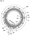
- twist processing can be performed using, for example, as shown in Fig. 13 , twisting jigs 150 to 155 respectively corresponding to the layers (six layers in the example of Fig. 13 ) formed by the distal end portions of the coil segments, having a diameter of D1 to D6, and having accommodating portions for accommodating distal end portions of the coil segments of the corresponding layer.
- twisting jigs 150 to 155 respectively corresponding to the layers (six layers in the example of Fig. 13 ) formed by the distal end portions of the coil segments, having a diameter of D1 to D6, and having accommodating portions for accommodating distal end portions of the coil segments of the corresponding layer.
- every two layers in order from the inside can be twisted, in a state where the respective distal end portions of the coil segments of the two layers are inserted into respective accommodating portions of two twisting jigs corresponding to the two layers, by rotating the two twist jigs in opposite directions as indicated by arrows R11 and R12.
- the portions close to the end face of the core 20 can be twisted in opposite directions for each layer, while keeping the upright state at portions of a predetermined length on the distal end side accommodated in the accommodating portion of the twisting jigs 150 to 155. Further, by moving the lead-side distal end portion 23 aside to a certain position not to be accommodated in the accommodating portion during the twist processing, the lead-side distal end portion 23 can be excluded from the twist processing.
- Fig. 14 shows an example of the distal end portions of the coil segments after the above twist processing.
- the method of twist processing is not limited to the above, and for example, the method described in Japanese Patent Application Laid-Open Publication No. 2003-259613 can be used.
- positional deviation may occur between the distal end portions facing each other in the radial direction of the core 20 and constituting the distal end pairs after the twist processing.
- the positional deviation may be a deviation in a sense that a pair of distal end portions to constitute a distal end pair are not sufficiently close to each other, or a deviation in a sense that position of a distal end pair is not aligned with the insertion hole, or both of them.
- a radial alignment operation may be performed on the distal end pairs 22 after the twist processing, before performing positioning with the positioning tool 4.
- This alignment operation can be performed using a known method as appropriate, for example, employing a positioning mechanism described in Japanese Patent Application Laid-Open Publication No. 2005-224028 . It is preferable to perform an alignment operation suitable for possible positional deviations that may occur, depending on the characteristics of the twisting apparatus. For example, if the deviation in the radial spacing between the distal end pairs is likely to occur, it is preferable to perform radial spacing alignment as the alignment operation.
- Such alignment operation after the twist processing is preferably performed in a space with less interference before the positioning tool 4 is set. Further, the alignment operation may be performed as a relatively rough positional adjustment with an accuracy to an extent that the respective distal end pairs and the lead-side distal end portions can be inserted into the later-described insertion holes. Circumferential alignment may be included.
- the positioning tool 4 is a positioning tool for positioning the distal end portions constituting the respective distal end pairs 22, before making connection, by welding or the like, on each of the distal end pairs 22 each constituted by a pair of distal end portions facing each other in the radial direction of the core 20 among the distal end portions of the coil segments protruding from the end face of the core 20.
- Fig. 3 is a plan view of the plate body 36 of the first plate 6.
- the reference numeral 60A denotes an ordered region corresponding to a portion in which only the ordinary segments protrude from the core 20, and the reference numeral 60B denotes a mixed region corresponding to a portion in which both the ordinary segments and the variant segments protrude from the core 20.
- insertion holes 62 (first insertion holes) each configured to separately accept insertion of one of the distal end pairs 22 of the ordinary segments are formed in lines along the circumferential direction of the core 20 to form a plurality of rows (three rows here) in the radial direction of the core 20.
- the insertion holes 62 include three types of: insertion holes 62a in the inner row in the radial direction; insertion holes 62b in the center row; and insertion holes 62c in the outer row.
- the inner insertion holes 62a and the outer insertion holes 62c have a larger width in the radial direction than the center insertion holes 62b. This is to make it easier, even if only slightly, to insert the distal end pairs 22 into the respective insertion holes 62a to 62c in consideration of the case where the positions of the distal end pairs 22 still somewhat miss the correct positions at the time of the insertion into the insertion holes.
- these insertion holes 62a, 62b, 62c have a tapered shape such that the width in the radial direction of the core 20 gradually narrows on the rear end side along the rotation direction (R1 direction) of the plate body 36 at the time of the positioning.
- both of insertion holes 62a, 62b, 62c each configured to separately accept insertion of one of the distal end pairs 22 of the ordinary segments, and variant insertion holes 64 (third insertion holes) each configured to accept insertion of a lead-side distal end portion 23 of a variant segment are formed.
- the variant insertion holes 64 are in rectangular shapes, and include two types of: inner variant insertion holes 64a having a larger width in the radial direction; and outer variant insertion holes 64b elongated in the circumferential direction. Since the variant insertion holes 64 do not have a positioning function, they do not have a tapered shape.
- Fig. 4 is a plan view of the plate body 42 of the second plate 8.
- corresponding insertion holes 62' (62a', 62b', 62c') (second insertion holes) respectively corresponding to the insertion holes 62 (62a, 62b, 62c) of the plate body 36
- corresponding variant insertion holes 64' (64a', 64b') (fourth insertion holes) respectively corresponding to the variant insertion holes 64 (64a, 64b) are formed.
- the corresponding insertion holes 62' are ones to perform the positioning of the distal end pairs in cooperation with the insertion holes 62, and for example, the corresponding insertion holes 62' have the same shapes as the insertion holes 62 and orientations in the circumferential direction opposite to those of the insertion holes 62. Since the corresponding variant insertion holes 64' do not have a positioning function, there is no difference in direction from the insertion holes 64.
- Fig. 5 shows a state in which the plate body 42 of the second plate 8 is superimposed on the plate body 36 of the first plate 6 in the axial direction of the core 20 (insertion direction of the distal end pairs 22).
- a region in which the insertion holes 62 and the corresponding insertion holes 62' overlap with each other and the variant insertion holes 64 and the corresponding variant insertion holes 64' overlap with each other is large.
- Fig. 6 shows a state after the rotation, i.e. after the positioning is completed.
- Fig. 7A shows a state where a distal end pair 22 (distal end portions 22a, 22b) is inserted into the insertion hole 62b and the corresponding insertion hole 62b' while the region in which the insertion hole 62b and the corresponding insertion hole 62b' overlap with each other is large. Since the position of each distal end pair 22 has been adjusted, the distal end pair 22 can be inserted within the region in which the insertion hole 62b and the corresponding insertion hole 62b' overlap with each other, with a margin.
- the adjustment of positions of the respective distal end portions 22a, 22b includes not only the adjustment of the relative positions between the respective distal end portions 22a, 22b, but also the alignment between the distal end pairs 22 and the insertion holes 62b and the corresponding insertion holes 62b' configured to accept insertion of the distal end pairs 22.
- distal end portions 22a and 22b are constrained by the rear end surface 62b of the insertion hole 62b-2 and the rear end surface 62b'-2 of the corresponding insertion hole 62', thereby the distal end portions 22a and 22b are aligned to a state with no positional deviation d1 in the circumferential direction. That is, positioning of the distal end pair 22 in the circumferential direction and the radial direction is performed simultaneously.
- Fig, 8A shows a state where a lead-side distal end portion 23 of a variant segment is inserted into the variant insertion hole 64b and the corresponding variant insertion hole 64b' while the region in which the variant insertion hole 64b and the corresponding variant insertion hole 64b' overlap with each other is large. Since the position of the lead-side distal end portion 23 has been adjusted, the lead-side distal end portion 23 can be inserted within the range in which the variant insertion hole 64b and the corresponding variant insertion hole 64' overlap with each other, with a margin. The same applies to the variant insertion hole 64a and the corresponding variant insertion hole 64a'.
- the sizes of the variant insertion hole 64b and the corresponding variant insertion hole 64b' are determined such that the lead-side distal end portion 23 is not constrained even in a state where the first plate 6 and the second plate 8 are rotated in opposite directions to the positions shown in Fig. 7B to perform the positioning of the distal end pair 22. Therefore, during the positioning of the distal end pairs 22, the positions of the lead-side distal end portions 23 do not change.
- the lead-side distal end portions 23 of the variant segments are not objects of the welding, it is not necessary to perform the positioning thereof.
- the lead-side distal end portions 23 are inserted into the first plate 6 and the second plate 8 so as not to interfere with the positioning operation of the distal end pairs 22, and are kept in a non-constrained state throughout the positioning operation of the distal end pairs 22.
- the reason why kept in the non-constrained state is that since parts of the lead-side distal end portions 23 at a height where other segments will be constrained are covered with an insulating film, it is intended to avoid scratches on the insulating film caused by collisions with other components, resulting in defects.
- distal end portions 22a, 22b constituting a distal end pair 22 are opposed to each other in the radial direction in a state after being bent though the twist operation. Therefore, a curved surface 62b-3 along the bent portion of the distal end portion 22b is formed at the lower end of the rear end surface 62b-2 of the insertion hole 62b in the plate body 36 of the first plate 6 located closer to the core 20 among the first plate 6 and the second plate 8, so that the positioning is not inhibited at the bent portion of the distal end portion (here, the distal end portion 22b) constituting the distal end pair 22.
- the rear end surface 62b-2 extends backward with respect to the rotational direction R1 of the first plate 6 during the positioning operation. Therefore, the bent portion of the distal end portion 22b does not interfere with the insertion hole 62b, and thus the positioning operation is not hindered.
- the positions of the twisted distal end pairs 22 are roughly adjusted to an extent that the twisted distal end pairs 22 can be inserted into the insertion holes of the first plate 6 and the second plate 8 (S11), and then the twisted distal end pairs 22 are inserted into the insertion holes 62 of the first plate 6 and the corresponding insertion holes 62' of the second plate 8 (S12).
- the lead-side distal end portions 23 are inserted into the variant insertion holes 64 of the first plate 6 and the corresponding variant insertion holes 64' of the second plate 8.
- the first plate 6 and the second plate 8 are rotated by the drive mechanism 16 in different directions, respectively, to narrow the region in which the insertion holes 62 of the first plate 6 and the corresponding insertion holes 62' of the second plate 8 overlap with each other, thereby the positioning of the distal end pair 22 is performed (S13).
- the insertion holes formed in the first plate 6 and the second plate 8 are independent of one another, the ratios of openings of the insertion holes to the areas of the plates are smaller than those in the apparatus shown in PTL1, and therefore the mechanical strength of the first plate 6 and the second plate 8 can be increased.
- the positions of the distal end pairs can be adjusted to a certain position at which the distal end pairs can be inserted into the insertion holes while the first plate 6 and the second plate 8 are not present, with easy access to the distal end portions of the coil segments, the work is easy, and the working efficiency of the positioning operation can be improved as a result.
- the above embodiment shows an example of a positioning tool having both of insertion holes for accepting insertion of distal end pairs of ordinary segments and insertion holes for accepting insertion of distal end portions of variant segments.
- a positioning tool having both of insertion holes for accepting insertion of distal end pairs of ordinary segments and insertion holes for accepting insertion of distal end portions of variant segments.
- another example of the positioning tool having only insertion holes for accepting insertion of distal end pairs of ordinary segments will be described with reference to Fig. 11 and Fig. 12 .
- the variant segment protrudes from the other end surface of the core on the opposite side to an end face side from which the ordinary segments protrude. Therefore, the segments on the side where the positioning is performed is only the ordinary segments, and the variant insertion holes are not necessary.
- Fig. 11 is a plan view of an annular plate body 66 to be fixed by screws on the upper surface of the inner side ring of the first plate.
- the reference numeral 66a denotes a screw insertion hole.
- insertion holes 68 each configured to separately accept insertion of one of the distal end pairs 22 are formed in lines along the circumferential direction of the core 20 to form a plurality of rows (four rows here) in the radial direction of the core 20.
- the number of distal end portions of the coil segments inserted into one slot of the core 20 is eight.
- the Insertion holes 68 includes, in order from the radially inner side of the core 20 toward the outer side, four types of the insertion holes 68a, 68b, 68c, and 68d. These insertion holes are in similar shapes, and the radial width and the circumferential width are gradually increased from the inner side ones toward the outer side ones. This is based on the difference in the amount of displacement in the circumferential direction due to the rotation depending on the radial position.
- the insertion holes 68a, 68b, 68c, 68d have, as in the case of Fig. 3 and Fig. 4 , a tapered shape such that the width in the radial direction gradually narrows on the rear end side along the rotational direction (R1 direction) of the plate body 66 at the time of the positioning.
- Fig. 12 is a plan view of an annular plate body 70 to be fixed by screws on the upper surface of the outer side ring of the second plate.
- the reference numeral 70a denotes a screw insertion hole
- 70b denotes an elongated hole in which the heads of the screws fixing the plate body 66 of the first plate can move.
- corresponding insertion holes 68' (68a', 68b', 68c', 68d') respectively corresponding to the insertion holes 68 (68a, 68b, 68c, 68d) of the plate body 66 are formed.
- the plate body 70 is disposed on the upper surface of the plate body 66 so as to overlap with the plate body 66 in the axial direction of the core 20, and is used in the same manner as the embodiment described with reference to Fig. 1 to Fig. 10 .
- the positioning function or the like by narrowing the region in which the insertion holes and the corresponding insertion hole overlap with each other is the same as that of the embodiment, and therefore the description thereof is omitted.
- the plate bodies are in an annular shape having an open center portion, but the plate bodies may be a disk shape. Further, as long as the insertion holes for accepting insertion of the distal end portions of the coil segments, which are objects of the positioning, can be formed, a member having a shape other than the plate shape can be used instead of the first plate and the second plate.
- the insertion holes 62 and the corresponding insertion holes 62' are gradually narrowed on the rear end side along the rotational direction.
- the insertion holes may have substantially the same width over the entire length in the rotational direction.
- the positioning of the distal end pair 22 cannot be performed in the radial direction by the rotation of the first plate 6 and the second plate 8, but the positioning in the circumferential direction can be performed in the same manner as in the above-described embodiment.
- curved surface 62b-3 shown in Fig. 9 is not essential.
- first plate 6 and the second plate 8 it is not essential to move both the first plate 6 and the second plate 8 during the positioning operation. Even with a configuration in which one of the first plate 6 and the second plate 8 is fixed and the other is moved, when the relative positional relationship between the first plate 6 and the second plate 8 is changed in a direction rotating around the axis of the core 20 through the above movement, and the region in which the insertion holes 62 and the corresponding insertion holes 62' overlap with each other in the axial direction of the core 20 can be narrowed, and thereby the positioning substantially the same as in the case of the embodiment described above can be performed.
- 2... positioning apparatus 4... positioning tool, 6... first plate, 8... second plate, 12... first operable member, 14... second operable member, 16... drive mechanism, 20... core, 22... distal end pair, 22a, 22b... distal end portion of coil segment, 23... lead-side distal end portion, 62, 62a, 62b, 62c... insertion hole, 62', 62a', 62b', 62c'... corresponding insertion hole, 64, 64a, 64b... variant insertion hole, 64', 64a' ,64b'... corresponding variant insertion hole
Landscapes
- Engineering & Computer Science (AREA)
- Manufacturing & Machinery (AREA)
- Power Engineering (AREA)
- Manufacture Of Motors, Generators (AREA)
Claims (10)
- Un procédé de positionnement de segments de bobine pour positionner une pluralité de paires d'extrémités distales (22) de segments de bobine faisant saillie depuis une face d'extrémité d'un noyau (20), chacune des paires d'extrémités distales (22) étant constituée par une paire de parties d'extrémités distales (22a, 22b) se faisant face dans une direction radiale du noyau (20) parmi les parties d'extrémités distales des segments de bobine, dans lequel le procédé comprend :préparer un premier élément (6) avec des premiers trous d'insertion (62) chacun configuré pour accepter séparément l'insertion de l'une des paires d'extrémités distales (22), les premiers trous d'insertion (62) étant disposés en lignes le long d'une direction circonférentielle du noyau (20) pour former une pluralité de rangées dans la direction radiale, et un second élément (8) avec des seconds trous d'insertion (62') correspondant aux premiers trous d'insertion (62) du premier élément (6) ;insérer les paires d'extrémités distales respectives (22) avec leurs positions ajustées dans une mesure telle que les paires d'extrémités distales (22) peuvent être insérées dans les premiers trous d'insertion (62) du premier élément (6) et dans les seconds trous d'insertion (62') du second élément (8), tandis que le second élément (8) est disposé pour chevaucher le premier élément (6) dans une direction axiale du noyau ; etaligner les positions, dans la direction circonférentielle, des parties d'extrémité distale (22a, 22b) constituant les paires d'extrémités distales respectives (22) insérées dans les premiers trous d'insertion (62) et les seconds trous d'insertion (62'), en faisant tourner le premier élément (6) et/ou le second élément (8) autour d'un axe du noyau (20) pour rétrécir une région dans laquelle les premiers trous d'insertion (62) et les seconds trous d'insertion (62') se chevauchent les uns les autres dans la direction axiale du noyau (20),dans lequel une ou plusieurs parties d'extrémité distale autonomes (23) ne constituant pas les paires d'extrémités distales (22) sont incluses dans les parties d'extrémité distale des segments de bobine faisant saillie de la face d'extrémité du noyau (20),un ou plusieurs troisièmes trous d'insertion (64) chacun configuré pour accepter l'insertion de l'une des parties d'extrémité distale autonomes (23) sont formés sur le premier élément (6), et un ou plusieurs quatrièmes trous d'insertion (64') configurés chacun pour accepter l'insertion de l'une des parties d'extrémité distale autonomes (64) sont formés sur le second élément (8),lors de l'insertion des paires d'extrémités distales respectives (22), dont les positions sont ajustées, dans les premiers trous d'insertion (62) et les seconds trous d'insertion (62'), les parties d'extrémités distales autonomes respectives (23) sont insérées dans les troisièmes trous d'insertion (64) et les quatrièmes trous d'insertion (64'), etles tailles des troisièmes trous d'insertion (64) et des quatrièmes trous d'insertion (64') sont telles que lorsque le premier élément (6) et/ou le second élément (8) est tourné vers une position dans laquelle les paires d'extrémités distales (22) insérées dans les premiers trous d'insertion (62) et les seconds trous d'insertion (62') sont contraintes par les premiers trous d'insertion (62) et les seconds trous d'insertion (62'), les parties d'extrémité distale autonomes respectives (23) insérées dans les troisièmes trous d'insertion (64) et les quatrièmes trous d'insertion (64') ne sont pas contraintes par les troisièmes trous d'insertion (64) et les quatrièmes trous d'insertion (64').
- Le procédé de positionnement de segments de bobine selon la revendication 1,
dans lequel le premier élément (6) et le second élément (8) sont tournés l'un à l'autre dans des directions opposées pour rétrécir la région dans laquelle le premier trou d'insertion (62) et le second trou d'insertion (62') se chevauchent l'un l'autre dans la direction axiale du noyau (20). - Le procédé de positionnement de segments de bobine selon la revendication 1 ou 2,
dans lequel au moins l'un ou l'autre des premiers trous d'insertion (62) et des seconds trous d'insertion (62') est formé de telle sorte que les largeurs de l'un ou l'autre des trous d'insertion, dans la direction radiale, sont plus étroites sur les côtés arrière de ceux-ci dans une direction de rotation dudit au moins un des trous d'insertion selon la rotation du premier élément (6) et/ou du second élément (8) que sur les côtés avant de ceux-ci dans la direction de la rotation, et lors de l'alignement des positions, dans la direction circonférentielle, des parties d'extrémités distales (20a, 20b) constituant chaque paire d'extrémités distales (22) par la rotation du premier élément (6) et/ou du second élément (8), les parties d'extrémités distales alignées (22a, 22b) sont amenées en contact les unes avec les autres dans la direction radiale. - Le procédé de positionnement de segments de bobine selon l'une quelconque des revendications 1 à 3,
dans lequel les surfaces internes (62b-2, 62b-3) de l'un ou l'autre des premiers trous d'insertion (62) et des seconds trous d'insertion (62'), qui sont plus proches du noyau (20), lorsque les paires d'extrémités distales (22) y sont insérées, sont configurées pour s'étendre vers l'arrière par rapport à une direction de rotation desdits l'un ou l'autre des trous d'insertion selon la rotation du premier élément (6) et/ou du second élément (8), sur un côté plus proche du noyau (20). - Un outil de positionnement de segments de bobine (4) comprenant :un premier élément (6) avec des premiers trous d'insertion (62) chacun configuré pour accepter séparément l'insertion d'une des paires d'extrémités distales (22) chacune constituée par une paire de parties d'extrémités distales (22a, 22b) se faisant face dans une direction radiale d'un noyau (20) parmi les parties d'extrémités distales de segments de bobine faisant saillie d'une face d'extrémité du noyau (20), les premiers trous d'insertion (62) étant disposés en lignes dans une direction circonférentielle du noyau (20) pour former une pluralité de rangées dans la direction radiale ; etun second élément (8) avec des seconds trous d'insertion (62') correspondant aux premiers trous d'insertion (62) du premier élément (6), configuré pour être disposé pour chevaucher le premier élément (6) dans une direction axiale du noyau (20) dans un état où les paires d'extrémités distales respectives (22) sont insérables dans les premiers trous d'insertion (62) et les seconds trous d'insertion (62'),dans lequel le premier élément (6) et/ou le second élément (8) est tournable autour d'un axe du noyau (20) dans une direction pour rétrécir une région dans laquelle les premiers trous d'insertion (62) et les seconds trous d'insertion (62') se chevauchent les uns les autres dans la direction axiale du noyau (20),le premier élément (6) comprend un ou plusieurs troisièmes trous d'insertion (64) chacun configuré pour accepter l'insertion d'une ou plusieurs parties d'extrémité distale autonomes (23) qui sont des parties d'extrémité distale ne constituant pas les paires d'extrémités distales (22) parmi les parties d'extrémité distale des segments de bobine faisant saillie de la face d'extrémité du noyau (20), et le second élément (8) comprend un ou plusieurs quatrièmes trous d'insertion (64') configurés chacun pour accepter l'insertion d'une des parties d'extrémité distale autonomes (23), etles tailles des troisièmes trous d'insertion (64) et des quatrièmes trous d'insertion (64') sont telles que lorsque le premier élément (6) et/ou le second élément (8) est tourné vers une position dans laquelle les paires d'extrémités distales (22) insérées dans les premiers trous d'insertion (62) et les seconds trous d'insertion (62') sont contraintes par les premiers trous d'insertion (62) et les seconds trous d'insertion (62'), les parties d'extrémité distale autonomes respectives (23) insérées dans les troisièmes trous d'insertion (64) et les quatrièmes trous d'insertion (64') ne sont pas contraintes par les troisièmes trous d'insertion (64) et les quatrièmes trous d'insertion (64').
- L'outil de positionnement de segments de bobine (4) selon la revendication 5,
dans lequel le premier élément (6) et le second élément (8) sont tous deux tournables l'un à l'autre dans des directions opposées pour rétrécir la région dans laquelle les premiers trous d'insertion (62) et les seconds trous d'insertion (62') se chevauchent dans la direction axiale du noyau (20). - L'outil de positionnement de segments de bobine (4) selon la revendication 5 ou 6,
dans lequel au moins l'un ou l'autre des premiers trous d'insertion (62) et des seconds trous d'insertion (62') est formé de telle sorte que les largeurs de l'un ou l'autre des trous d'insertion, dans la direction radiale, sont plus étroites sur les côtés arrière de ceux-ci dans une direction de rotation dudit au moins un des trous d'insertion selon la rotation du premier élément (6) et/ou du second élément (8) que sur les côtés avant de ceux-ci dans la direction de la rotation. - L'outil de positionnement de segments de bobine (4) selon l'une quelconque des revendications 5 à 7,
dans lequel les surfaces internes (62b-2, 62b-3) de l'un ou l'autre des premiers trous d'insertion (62) et des seconds trous d'insertion (62'), qui se rapprochent du noyau (20) lorsque les paires d'extrémités distales (22) y sont insérées, sont configurées pour s'étendre vers l'arrière par rapport à une direction de rotation desdits l'un ou l'autre des trous d'insertion selon la rotation du premier élément (6) et/ou du second élément (8), sur un côté plus proche du noyau. - Un appareil de positionnement de segments de bobine (2), comprenant :l'outil de positionnement de segment de bobine (4) selon l'une quelconque des revendications 5 à 8 ; etun mécanisme d'entraînement (16) configuré pour faire tourner le premier élément (6) et le second élément (8) dans des directions différentes, respectivement.
- L'appareil de positionnement de segments de bobine (2) selon la revendication 9, comprenant :un élément de base (10) configuré pour supporter le premier élément (6) et le second élément (8) ;un premier élément opérable (12) formé sur le premier élément (6) ; etun second élément opérable (14) formé sur le second élément (8),dans lequel le mécanisme d'entraînement (16) est configuré pour faire tourner le premier élément (6) et le second élément (8) dans les différentes directions en rapprochant ou en éloignant le premier élément opérable (12) et le second élément opérable (14) l'un de l'autre.
Applications Claiming Priority (2)
| Application Number | Priority Date | Filing Date | Title |
|---|---|---|---|
| JP2018055374 | 2018-03-22 | ||
| PCT/JP2019/012226 WO2019182144A1 (fr) | 2018-03-22 | 2019-03-22 | Procédé de positionnement de segment de bobine, outil de positionnement de segment de bobine, et dispositif de positionnement de segment de bobine |
Publications (3)
| Publication Number | Publication Date |
|---|---|
| EP3761490A1 EP3761490A1 (fr) | 2021-01-06 |
| EP3761490A4 EP3761490A4 (fr) | 2021-05-26 |
| EP3761490B1 true EP3761490B1 (fr) | 2023-02-22 |
Family
ID=67987362
Family Applications (1)
| Application Number | Title | Priority Date | Filing Date |
|---|---|---|---|
| EP19770309.3A Active EP3761490B1 (fr) | 2018-03-22 | 2019-03-22 | Procédé de positionnement de segment de bobine, outil de positionnement de segment de bobine, et dispositif de positionnement de segment de bobine |
Country Status (5)
| Country | Link |
|---|---|
| US (1) | US11387721B2 (fr) |
| EP (1) | EP3761490B1 (fr) |
| JP (1) | JP6667869B2 (fr) |
| CN (1) | CN111937281B (fr) |
| WO (1) | WO2019182144A1 (fr) |
Families Citing this family (6)
| Publication number | Priority date | Publication date | Assignee | Title |
|---|---|---|---|---|
| DE102018103100A1 (de) | 2017-07-04 | 2019-01-10 | Grob-Werke Gmbh & Co. Kg | Verfahren und Vorrichtung zum Positionieren und Spannen von Drahtenden für elektrische Maschinen |
| EP4084305A4 (fr) | 2020-01-22 | 2023-08-09 | Odawara Engineering Co., Ltd. | Procédé de torsion de segment de bobine, gabarit de torsion et dispositif de torsion |
| DE102020119587A1 (de) * | 2020-07-24 | 2022-01-27 | Pro-Beam Gmbh & Co. Kgaa | Positioniervorrichtung und Verfahren zum Positionieren von Drahtenden bei der Herstellung einer elektrischen Maschine |
| DE102022208704A1 (de) * | 2022-08-23 | 2024-02-29 | Vitesco Technologies Germany Gmbh | Spannvorrichtung für das Schweißen von Haarnadelwicklungen |
| JPWO2024201697A1 (fr) * | 2023-03-28 | 2024-10-03 | ||
| DE102023206903A1 (de) * | 2023-07-20 | 2025-01-23 | Volkswagen Aktiengesellschaft | Verfahren zum Herstellen eines Stators für eine Elektromaschine und Elektromaschine |
Citations (1)
| Publication number | Priority date | Publication date | Assignee | Title |
|---|---|---|---|---|
| WO2019007459A1 (fr) * | 2017-07-04 | 2019-01-10 | Grob-Werke Gmbh & Co. Kg | Procédé et dispositif de positionnement et de serrage d'extrémités de fil pour machines électriques |
Family Cites Families (11)
| Publication number | Priority date | Publication date | Assignee | Title |
|---|---|---|---|---|
| JP2003259613A (ja) * | 2002-02-27 | 2003-09-12 | Denso Corp | 回転電機の固定子巻線の製造方法 |
| JP3829769B2 (ja) * | 2002-07-18 | 2006-10-04 | 株式会社デンソー | 回転電機の固定子巻線の製造方法 |
| JP4114588B2 (ja) * | 2003-10-22 | 2008-07-09 | トヨタ自動車株式会社 | セグメント位置決め装置、及び、ステータの製造方法 |
| JP2005224028A (ja) | 2004-02-06 | 2005-08-18 | Toyota Motor Corp | セグメントコイル接合装置および方法 |
| DE112011100868T5 (de) * | 2010-03-11 | 2012-12-27 | Kabushiki Kaisha Toyota Jidoshokki | Stator für eine rotierende elektrische Maschine, Herstellungsverfahren eines Stators und Herstellungsverfahren einer Wicklung für einen Stator |
| ITTO20110199A1 (it) | 2011-03-07 | 2012-09-08 | Atop Spa | Apparecchio e procedimento per l'allineamento di conduttori di elementi di bobine in nuclei di macchine dinamo elettriche per compiere operazioni di saldatura. |
| JP5841017B2 (ja) * | 2012-07-12 | 2016-01-06 | 本田技研工業株式会社 | 電気導体の挿入装置 |
| JP6203085B2 (ja) * | 2014-03-07 | 2017-09-27 | 平田機工株式会社 | 位置決め部材、位置決め装置及びステータの製造方法 |
| DE102014208082B4 (de) * | 2014-04-29 | 2019-03-07 | Continental Automotive Gmbh | Verfahren und Vorrichtung zum Herstellen einer Wicklung einer elektrischen Maschine |
| JP6170545B2 (ja) * | 2015-12-22 | 2017-07-26 | 本田技研工業株式会社 | 回転電機の製造装置及び回転電機の製造方法 |
| US10992209B2 (en) | 2016-03-18 | 2021-04-27 | Honda Motor Co., Ltd. | Locator-equipped clamp jig, stator manufacturing device, and method for manufacturing stator |
-
2019
- 2019-03-22 WO PCT/JP2019/012226 patent/WO2019182144A1/fr not_active Ceased
- 2019-03-22 JP JP2019568794A patent/JP6667869B2/ja active Active
- 2019-03-22 EP EP19770309.3A patent/EP3761490B1/fr active Active
- 2019-03-22 CN CN201980020700.8A patent/CN111937281B/zh active Active
-
2020
- 2020-09-21 US US17/026,943 patent/US11387721B2/en active Active
Patent Citations (1)
| Publication number | Priority date | Publication date | Assignee | Title |
|---|---|---|---|---|
| WO2019007459A1 (fr) * | 2017-07-04 | 2019-01-10 | Grob-Werke Gmbh & Co. Kg | Procédé et dispositif de positionnement et de serrage d'extrémités de fil pour machines électriques |
Also Published As
| Publication number | Publication date |
|---|---|
| CN111937281B (zh) | 2023-06-27 |
| EP3761490A1 (fr) | 2021-01-06 |
| JPWO2019182144A1 (ja) | 2020-04-30 |
| JP6667869B2 (ja) | 2020-03-18 |
| US11387721B2 (en) | 2022-07-12 |
| CN111937281A (zh) | 2020-11-13 |
| EP3761490A4 (fr) | 2021-05-26 |
| US20210006140A1 (en) | 2021-01-07 |
| WO2019182144A1 (fr) | 2019-09-26 |
Similar Documents
| Publication | Publication Date | Title |
|---|---|---|
| EP3761490B1 (fr) | Procédé de positionnement de segment de bobine, outil de positionnement de segment de bobine, et dispositif de positionnement de segment de bobine | |
| EP2800246B1 (fr) | Machine électrique rotative et procédé de fabrication de stator | |
| JP3196738B2 (ja) | ステータ製造装置及びステータ製造方法 | |
| US11557931B2 (en) | Stator with dual jig arrangement | |
| EP3675330B1 (fr) | Stator, procédé de fabrication d'un stator, bobine et procédé de fabrication d'une bobine | |
| CN113196632A (zh) | 定位发卡式导体的至少第一支脚对的端部的装置和方法 | |
| US10305355B2 (en) | Stator manufacturing method and coil | |
| US20130162072A1 (en) | Method for manufacturing stator, apparatus for manufacturing stator, and stator | |
| CN111226380A (zh) | 定位和夹紧电机导线端部的方法和装置 | |
| US20210408849A1 (en) | Rotary electric machine stator core and manufacturing method therefor | |
| JP6848131B1 (ja) | 固定子および固定子の製造方法 | |
| US20240416452A1 (en) | Laser welding method and method for manufacturing rotary electrical machine | |
| JPWO2020100311A1 (ja) | 固定子の製造方法 | |
| US20200099266A1 (en) | Stator manufacturing method | |
| WO2021144898A1 (fr) | Procédé de fabrication de stator | |
| JP7327268B2 (ja) | ステータ製造装置 | |
| JP6848129B1 (ja) | 固定子の製造方法および固定子の製造装置 | |
| JP3734160B2 (ja) | 回転電機のステータの製造方法 | |
| US10951096B2 (en) | Method and apparatus for producing rotating electric machine stator | |
| JP7503353B2 (ja) | セグメントコイルの溶接装置及び回転電機のステータの製造方法 | |
| JP7814662B2 (ja) | 回転電機用ステータ及び回転電機 | |
| JP2025166416A (ja) | ステータの製造装置 | |
| JP2022019465A (ja) | 捻り加工装置および捻り加工方法 | |
| CN217669111U (zh) | 用于拼块式定子的装配工装 | |
| WO2026062760A1 (fr) | Procédé de fabrication de stator de machine électrique rotative et procédé de fabrication de machine électrique rotative |
Legal Events
| Date | Code | Title | Description |
|---|---|---|---|
| STAA | Information on the status of an ep patent application or granted ep patent |
Free format text: STATUS: THE INTERNATIONAL PUBLICATION HAS BEEN MADE |
|
| PUAI | Public reference made under article 153(3) epc to a published international application that has entered the european phase |
Free format text: ORIGINAL CODE: 0009012 |
|
| STAA | Information on the status of an ep patent application or granted ep patent |
Free format text: STATUS: REQUEST FOR EXAMINATION WAS MADE |
|
| 17P | Request for examination filed |
Effective date: 20200930 |
|
| AK | Designated contracting states |
Kind code of ref document: A1 Designated state(s): AL AT BE BG CH CY CZ DE DK EE ES FI FR GB GR HR HU IE IS IT LI LT LU LV MC MK MT NL NO PL PT RO RS SE SI SK SM TR |
|
| AX | Request for extension of the european patent |
Extension state: BA ME |
|
| A4 | Supplementary search report drawn up and despatched |
Effective date: 20210428 |
|
| RIC1 | Information provided on ipc code assigned before grant |
Ipc: H02K 15/085 20060101AFI20210421BHEP Ipc: H02K 3/04 20060101ALI20210421BHEP Ipc: H02K 15/00 20060101ALI20210421BHEP |
|
| TPAC | Observations filed by third parties |
Free format text: ORIGINAL CODE: EPIDOSNTIPA |
|
| DAV | Request for validation of the european patent (deleted) | ||
| DAX | Request for extension of the european patent (deleted) | ||
| STAA | Information on the status of an ep patent application or granted ep patent |
Free format text: STATUS: EXAMINATION IS IN PROGRESS |
|
| 17Q | First examination report despatched |
Effective date: 20220113 |
|
| GRAP | Despatch of communication of intention to grant a patent |
Free format text: ORIGINAL CODE: EPIDOSNIGR1 |
|
| STAA | Information on the status of an ep patent application or granted ep patent |
Free format text: STATUS: GRANT OF PATENT IS INTENDED |
|
| INTG | Intention to grant announced |
Effective date: 20220905 |
|
| RIN1 | Information on inventor provided before grant (corrected) |
Inventor name: HONDA, RYO Inventor name: MIYAWAKI, NOBURO |
|
| GRAS | Grant fee paid |
Free format text: ORIGINAL CODE: EPIDOSNIGR3 |
|
| GRAA | (expected) grant |
Free format text: ORIGINAL CODE: 0009210 |
|
| STAA | Information on the status of an ep patent application or granted ep patent |
Free format text: STATUS: THE PATENT HAS BEEN GRANTED |
|
| AK | Designated contracting states |
Kind code of ref document: B1 Designated state(s): AL AT BE BG CH CY CZ DE DK EE ES FI FR GB GR HR HU IE IS IT LI LT LU LV MC MK MT NL NO PL PT RO RS SE SI SK SM TR |
|
| REG | Reference to a national code |
Ref country code: GB Ref legal event code: FG4D |
|
| REG | Reference to a national code |
Ref country code: CH Ref legal event code: EP |
|
| REG | Reference to a national code |
Ref country code: AT Ref legal event code: REF Ref document number: 1550139 Country of ref document: AT Kind code of ref document: T Effective date: 20230315 Ref country code: IE Ref legal event code: FG4D |
|
| REG | Reference to a national code |
Ref country code: DE Ref legal event code: R096 Ref document number: 602019025569 Country of ref document: DE |
|
| REG | Reference to a national code |
Ref country code: LT Ref legal event code: MG9D |
|
| REG | Reference to a national code |
Ref country code: NL Ref legal event code: MP Effective date: 20230222 |
|
| REG | Reference to a national code |
Ref country code: AT Ref legal event code: MK05 Ref document number: 1550139 Country of ref document: AT Kind code of ref document: T Effective date: 20230222 |
|
| PG25 | Lapsed in a contracting state [announced via postgrant information from national office to epo] |
Ref country code: RS Free format text: LAPSE BECAUSE OF FAILURE TO SUBMIT A TRANSLATION OF THE DESCRIPTION OR TO PAY THE FEE WITHIN THE PRESCRIBED TIME-LIMIT Effective date: 20230222 Ref country code: PT Free format text: LAPSE BECAUSE OF FAILURE TO SUBMIT A TRANSLATION OF THE DESCRIPTION OR TO PAY THE FEE WITHIN THE PRESCRIBED TIME-LIMIT Effective date: 20230622 Ref country code: NO Free format text: LAPSE BECAUSE OF FAILURE TO SUBMIT A TRANSLATION OF THE DESCRIPTION OR TO PAY THE FEE WITHIN THE PRESCRIBED TIME-LIMIT Effective date: 20230522 Ref country code: NL Free format text: LAPSE BECAUSE OF FAILURE TO SUBMIT A TRANSLATION OF THE DESCRIPTION OR TO PAY THE FEE WITHIN THE PRESCRIBED TIME-LIMIT Effective date: 20230222 Ref country code: LV Free format text: LAPSE BECAUSE OF FAILURE TO SUBMIT A TRANSLATION OF THE DESCRIPTION OR TO PAY THE FEE WITHIN THE PRESCRIBED TIME-LIMIT Effective date: 20230222 Ref country code: LT Free format text: LAPSE BECAUSE OF FAILURE TO SUBMIT A TRANSLATION OF THE DESCRIPTION OR TO PAY THE FEE WITHIN THE PRESCRIBED TIME-LIMIT Effective date: 20230222 Ref country code: HR Free format text: LAPSE BECAUSE OF FAILURE TO SUBMIT A TRANSLATION OF THE DESCRIPTION OR TO PAY THE FEE WITHIN THE PRESCRIBED TIME-LIMIT Effective date: 20230222 Ref country code: ES Free format text: LAPSE BECAUSE OF FAILURE TO SUBMIT A TRANSLATION OF THE DESCRIPTION OR TO PAY THE FEE WITHIN THE PRESCRIBED TIME-LIMIT Effective date: 20230222 Ref country code: AT Free format text: LAPSE BECAUSE OF FAILURE TO SUBMIT A TRANSLATION OF THE DESCRIPTION OR TO PAY THE FEE WITHIN THE PRESCRIBED TIME-LIMIT Effective date: 20230222 |
|
| PG25 | Lapsed in a contracting state [announced via postgrant information from national office to epo] |
Ref country code: SE Free format text: LAPSE BECAUSE OF FAILURE TO SUBMIT A TRANSLATION OF THE DESCRIPTION OR TO PAY THE FEE WITHIN THE PRESCRIBED TIME-LIMIT Effective date: 20230222 Ref country code: PL Free format text: LAPSE BECAUSE OF FAILURE TO SUBMIT A TRANSLATION OF THE DESCRIPTION OR TO PAY THE FEE WITHIN THE PRESCRIBED TIME-LIMIT Effective date: 20230222 Ref country code: IS Free format text: LAPSE BECAUSE OF FAILURE TO SUBMIT A TRANSLATION OF THE DESCRIPTION OR TO PAY THE FEE WITHIN THE PRESCRIBED TIME-LIMIT Effective date: 20230622 Ref country code: GR Free format text: LAPSE BECAUSE OF FAILURE TO SUBMIT A TRANSLATION OF THE DESCRIPTION OR TO PAY THE FEE WITHIN THE PRESCRIBED TIME-LIMIT Effective date: 20230523 Ref country code: FI Free format text: LAPSE BECAUSE OF FAILURE TO SUBMIT A TRANSLATION OF THE DESCRIPTION OR TO PAY THE FEE WITHIN THE PRESCRIBED TIME-LIMIT Effective date: 20230222 |
|
| PG25 | Lapsed in a contracting state [announced via postgrant information from national office to epo] |
Ref country code: SM Free format text: LAPSE BECAUSE OF FAILURE TO SUBMIT A TRANSLATION OF THE DESCRIPTION OR TO PAY THE FEE WITHIN THE PRESCRIBED TIME-LIMIT Effective date: 20230222 Ref country code: RO Free format text: LAPSE BECAUSE OF FAILURE TO SUBMIT A TRANSLATION OF THE DESCRIPTION OR TO PAY THE FEE WITHIN THE PRESCRIBED TIME-LIMIT Effective date: 20230222 Ref country code: EE Free format text: LAPSE BECAUSE OF FAILURE TO SUBMIT A TRANSLATION OF THE DESCRIPTION OR TO PAY THE FEE WITHIN THE PRESCRIBED TIME-LIMIT Effective date: 20230222 Ref country code: DK Free format text: LAPSE BECAUSE OF FAILURE TO SUBMIT A TRANSLATION OF THE DESCRIPTION OR TO PAY THE FEE WITHIN THE PRESCRIBED TIME-LIMIT Effective date: 20230222 Ref country code: CZ Free format text: LAPSE BECAUSE OF FAILURE TO SUBMIT A TRANSLATION OF THE DESCRIPTION OR TO PAY THE FEE WITHIN THE PRESCRIBED TIME-LIMIT Effective date: 20230222 |
|
| REG | Reference to a national code |
Ref country code: CH Ref legal event code: PL |
|
| REG | Reference to a national code |
Ref country code: DE Ref legal event code: R097 Ref document number: 602019025569 Country of ref document: DE |
|
| PG25 | Lapsed in a contracting state [announced via postgrant information from national office to epo] |
Ref country code: SK Free format text: LAPSE BECAUSE OF FAILURE TO SUBMIT A TRANSLATION OF THE DESCRIPTION OR TO PAY THE FEE WITHIN THE PRESCRIBED TIME-LIMIT Effective date: 20230222 |
|
| REG | Reference to a national code |
Ref country code: BE Ref legal event code: MM Effective date: 20230331 |
|
| PG25 | Lapsed in a contracting state [announced via postgrant information from national office to epo] |
Ref country code: LU Free format text: LAPSE BECAUSE OF NON-PAYMENT OF DUE FEES Effective date: 20230322 |
|
| PLBE | No opposition filed within time limit |
Free format text: ORIGINAL CODE: 0009261 |
|
| STAA | Information on the status of an ep patent application or granted ep patent |
Free format text: STATUS: NO OPPOSITION FILED WITHIN TIME LIMIT |
|
| PG25 | Lapsed in a contracting state [announced via postgrant information from national office to epo] |
Ref country code: MC Free format text: LAPSE BECAUSE OF FAILURE TO SUBMIT A TRANSLATION OF THE DESCRIPTION OR TO PAY THE FEE WITHIN THE PRESCRIBED TIME-LIMIT Effective date: 20230222 |
|
| REG | Reference to a national code |
Ref country code: IE Ref legal event code: MM4A |
|
| GBPC | Gb: european patent ceased through non-payment of renewal fee |
Effective date: 20230522 |
|
| 26N | No opposition filed |
Effective date: 20231123 |
|
| PG25 | Lapsed in a contracting state [announced via postgrant information from national office to epo] |
Ref country code: SI Free format text: LAPSE BECAUSE OF FAILURE TO SUBMIT A TRANSLATION OF THE DESCRIPTION OR TO PAY THE FEE WITHIN THE PRESCRIBED TIME-LIMIT Effective date: 20230222 Ref country code: MC Free format text: LAPSE BECAUSE OF FAILURE TO SUBMIT A TRANSLATION OF THE DESCRIPTION OR TO PAY THE FEE WITHIN THE PRESCRIBED TIME-LIMIT Effective date: 20230222 Ref country code: LI Free format text: LAPSE BECAUSE OF NON-PAYMENT OF DUE FEES Effective date: 20230331 Ref country code: IE Free format text: LAPSE BECAUSE OF NON-PAYMENT OF DUE FEES Effective date: 20230322 Ref country code: FR Free format text: LAPSE BECAUSE OF NON-PAYMENT OF DUE FEES Effective date: 20230422 Ref country code: CH Free format text: LAPSE BECAUSE OF NON-PAYMENT OF DUE FEES Effective date: 20230331 |
|
| PG25 | Lapsed in a contracting state [announced via postgrant information from national office to epo] |
Ref country code: BE Free format text: LAPSE BECAUSE OF NON-PAYMENT OF DUE FEES Effective date: 20230331 |
|
| PG25 | Lapsed in a contracting state [announced via postgrant information from national office to epo] |
Ref country code: GB Free format text: LAPSE BECAUSE OF NON-PAYMENT OF DUE FEES Effective date: 20230522 |
|
| PG25 | Lapsed in a contracting state [announced via postgrant information from national office to epo] |
Ref country code: IT Free format text: LAPSE BECAUSE OF FAILURE TO SUBMIT A TRANSLATION OF THE DESCRIPTION OR TO PAY THE FEE WITHIN THE PRESCRIBED TIME-LIMIT Effective date: 20230222 |
|
| PG25 | Lapsed in a contracting state [announced via postgrant information from national office to epo] |
Ref country code: BG Free format text: LAPSE BECAUSE OF FAILURE TO SUBMIT A TRANSLATION OF THE DESCRIPTION OR TO PAY THE FEE WITHIN THE PRESCRIBED TIME-LIMIT Effective date: 20230222 |
|
| PG25 | Lapsed in a contracting state [announced via postgrant information from national office to epo] |
Ref country code: BG Free format text: LAPSE BECAUSE OF FAILURE TO SUBMIT A TRANSLATION OF THE DESCRIPTION OR TO PAY THE FEE WITHIN THE PRESCRIBED TIME-LIMIT Effective date: 20230222 |
|
| PG25 | Lapsed in a contracting state [announced via postgrant information from national office to epo] |
Ref country code: CY Free format text: LAPSE BECAUSE OF FAILURE TO SUBMIT A TRANSLATION OF THE DESCRIPTION OR TO PAY THE FEE WITHIN THE PRESCRIBED TIME-LIMIT; INVALID AB INITIO Effective date: 20190322 |
|
| PG25 | Lapsed in a contracting state [announced via postgrant information from national office to epo] |
Ref country code: HU Free format text: LAPSE BECAUSE OF FAILURE TO SUBMIT A TRANSLATION OF THE DESCRIPTION OR TO PAY THE FEE WITHIN THE PRESCRIBED TIME-LIMIT; INVALID AB INITIO Effective date: 20190322 |
|
| PG25 | Lapsed in a contracting state [announced via postgrant information from national office to epo] |
Ref country code: TR Free format text: LAPSE BECAUSE OF FAILURE TO SUBMIT A TRANSLATION OF THE DESCRIPTION OR TO PAY THE FEE WITHIN THE PRESCRIBED TIME-LIMIT Effective date: 20230222 |
|
| PGFP | Annual fee paid to national office [announced via postgrant information from national office to epo] |
Ref country code: DE Payment date: 20260325 Year of fee payment: 8 |