EP3761492B1 - Circuit d'amortissement et module d'alimentation à semi-conducteur ayant un circuit d'amortissement - Google Patents
Circuit d'amortissement et module d'alimentation à semi-conducteur ayant un circuit d'amortissement Download PDFInfo
- Publication number
- EP3761492B1 EP3761492B1 EP19184691.4A EP19184691A EP3761492B1 EP 3761492 B1 EP3761492 B1 EP 3761492B1 EP 19184691 A EP19184691 A EP 19184691A EP 3761492 B1 EP3761492 B1 EP 3761492B1
- Authority
- EP
- European Patent Office
- Prior art keywords
- electrically
- snubber circuit
- snubber
- capacitor
- layers
- Prior art date
- Legal status (The legal status is an assumption and is not a legal conclusion. Google has not performed a legal analysis and makes no representation as to the accuracy of the status listed.)
- Active
Links
Images


Classifications
-
- H—ELECTRICITY
- H05—ELECTRIC TECHNIQUES NOT OTHERWISE PROVIDED FOR
- H05K—PRINTED CIRCUITS; CASINGS OR CONSTRUCTIONAL DETAILS OF ELECTRIC APPARATUS; MANUFACTURE OF ASSEMBLAGES OF ELECTRICAL COMPONENTS
- H05K1/00—Printed circuits
- H05K1/16—Printed circuits incorporating printed electric components, e.g. printed resistors, capacitors or inductors
- H05K1/167—Printed circuits incorporating printed electric components, e.g. printed resistors, capacitors or inductors incorporating printed resistors
-
- H—ELECTRICITY
- H02—GENERATION; CONVERSION OR DISTRIBUTION OF ELECTRIC POWER
- H02M—APPARATUS FOR CONVERSION BETWEEN AC AND AC, BETWEEN AC AND DC, OR BETWEEN DC AND DC, AND FOR USE WITH MAINS OR SIMILAR POWER SUPPLY SYSTEMS; CONVERSION OF DC OR AC INPUT POWER INTO SURGE OUTPUT POWER; CONTROL OR REGULATION THEREOF
- H02M1/00—Details of apparatus for conversion
- H02M1/32—Means for protecting converters other than automatic disconnection
- H02M1/34—Snubber circuits
-
- H—ELECTRICITY
- H02—GENERATION; CONVERSION OR DISTRIBUTION OF ELECTRIC POWER
- H02H—EMERGENCY PROTECTIVE CIRCUIT ARRANGEMENTS
- H02H9/00—Emergency protective circuit arrangements for limiting excess current or voltage without disconnection
- H02H9/005—Emergency protective circuit arrangements for limiting excess current or voltage without disconnection avoiding undesired transient conditions
-
- H—ELECTRICITY
- H03—ELECTRONIC CIRCUITRY
- H03K—PULSE TECHNIQUE
- H03K17/00—Electronic switching or gating, i.e. not by contact-making and –breaking
- H03K17/08—Modifications for protecting switching circuit against overcurrent or overvoltage
- H03K17/081—Modifications for protecting switching circuit against overcurrent or overvoltage without feedback from the output circuit to the control circuit
- H03K17/0814—Modifications for protecting switching circuit against overcurrent or overvoltage without feedback from the output circuit to the control circuit by measures taken in the output circuit
- H03K17/08142—Modifications for protecting switching circuit against overcurrent or overvoltage without feedback from the output circuit to the control circuit by measures taken in the output circuit in field-effect transistor switches
-
- H—ELECTRICITY
- H03—ELECTRONIC CIRCUITRY
- H03K—PULSE TECHNIQUE
- H03K17/00—Electronic switching or gating, i.e. not by contact-making and –breaking
- H03K17/16—Modifications for eliminating interference voltages or currents
- H03K17/161—Modifications for eliminating interference voltages or currents in field-effect transistor switches
-
- H—ELECTRICITY
- H03—ELECTRONIC CIRCUITRY
- H03K—PULSE TECHNIQUE
- H03K19/00—Logic circuits, i.e. having at least two inputs acting on one output; Inverting circuits
- H03K19/0175—Coupling arrangements; Interface arrangements
- H03K19/0185—Coupling arrangements; Interface arrangements using field effect transistors only
-
- H—ELECTRICITY
- H05—ELECTRIC TECHNIQUES NOT OTHERWISE PROVIDED FOR
- H05K—PRINTED CIRCUITS; CASINGS OR CONSTRUCTIONAL DETAILS OF ELECTRIC APPARATUS; MANUFACTURE OF ASSEMBLAGES OF ELECTRICAL COMPONENTS
- H05K1/00—Printed circuits
- H05K1/16—Printed circuits incorporating printed electric components, e.g. printed resistors, capacitors or inductors
- H05K1/162—Printed circuits incorporating printed electric components, e.g. printed resistors, capacitors or inductors incorporating printed capacitors
-
- H—ELECTRICITY
- H05—ELECTRIC TECHNIQUES NOT OTHERWISE PROVIDED FOR
- H05K—PRINTED CIRCUITS; CASINGS OR CONSTRUCTIONAL DETAILS OF ELECTRIC APPARATUS; MANUFACTURE OF ASSEMBLAGES OF ELECTRICAL COMPONENTS
- H05K1/00—Printed circuits
- H05K1/18—Printed circuits structurally associated with non-printed electric components
- H05K1/182—Printed circuits structurally associated with non-printed electric components associated with components mounted in printed circuit boards [PCB], e.g. insert-mounted components [IMC]
-
- H—ELECTRICITY
- H02—GENERATION; CONVERSION OR DISTRIBUTION OF ELECTRIC POWER
- H02M—APPARATUS FOR CONVERSION BETWEEN AC AND AC, BETWEEN AC AND DC, OR BETWEEN DC AND DC, AND FOR USE WITH MAINS OR SIMILAR POWER SUPPLY SYSTEMS; CONVERSION OF DC OR AC INPUT POWER INTO SURGE OUTPUT POWER; CONTROL OR REGULATION THEREOF
- H02M1/00—Details of apparatus for conversion
- H02M1/32—Means for protecting converters other than automatic disconnection
- H02M1/34—Snubber circuits
- H02M1/348—Passive dissipative snubbers
-
- H—ELECTRICITY
- H10—SEMICONDUCTOR DEVICES; ELECTRIC SOLID-STATE DEVICES NOT OTHERWISE PROVIDED FOR
- H10D—INORGANIC ELECTRIC SEMICONDUCTOR DEVICES
- H10D62/00—Semiconductor bodies, or regions thereof, of devices having potential barriers
- H10D62/80—Semiconductor bodies, or regions thereof, of devices having potential barriers characterised by the materials
- H10D62/83—Semiconductor bodies, or regions thereof, of devices having potential barriers characterised by the materials being Group IV materials, e.g. B-doped Si or undoped Ge
- H10D62/832—Semiconductor bodies, or regions thereof, of devices having potential barriers characterised by the materials being Group IV materials, e.g. B-doped Si or undoped Ge being Group IV materials comprising two or more elements, e.g. SiGe
- H10D62/8325—Silicon carbide
Definitions
- the disclosure relates to a snubber circuit and a power semiconductor module with a snubber circuit.
- Switche circuits or simply put “snubbers” are frequently used in electrical systems with an inductive load where the sudden interruption of current flowing through the load leads to a sharp rise in voltage across a current switching device (shortly "switching device”).
- An accordingly generated current transient can be a source of electromagnetic interference (EMI) in other circuits.
- EMI electromagnetic interference
- the snubber provides a short-term alternative current path around the switching device so that the inductive element may be safely discharged.
- a simple RC snubber uses a resistor (R) in series with a capacitor (C).
- R resistor
- C capacitor
- An appropriately-designed RC snubber can be used to limit the peak voltage across the switching device when switching an inductive load with either direct current (DC) or alternating current (AC).
- DC direct current
- AC alternating current
- the voltage across the capacitor cannot change instantaneously, so a decreasing transient current will flow through the capacitor for a short time, allowing the voltage across the switching device to increase more slowly when the switching device is opened.
- a simple rectifier diode may be employed as a diode snubber (also referred to as free-wheeling diode, snubber diode, suppressor diode, or catch diode).
- the diode is wired in parallel with the inductive load such that it does not conduct under normal operating conditions.
- the inductor current flows through the diode instead of the switching device.
- the stored energy of the inductive load is then gradually dissipated by the diode voltage drop and the resistance of the inductive load.
- the diode must immediately enter into forward conduction mode when the driving current is interrupted.
- patent application publication US 2012/147641 A1 discloses a switching device that includes a flowing restriction element, a conductor and a snubber resistor.
- the flowing restriction element has an opening and closing function to open and close a flowing path of an electric current.
- the conductor is connected to the flowing restriction element.
- the snubber resistor is connected to the flowing restriction element and constitutes a snubber circuit.
- the snubber resistor is disposed along the conductor.
- Patent application publication JP 2008 166301 A discloses an electronic component including terminal electrodes at an end portion of an electronic component body such as a multilayer ceramic capacitor chip. Part of the conductor layer constituting the terminal electrodes is formed away from other members.
- the conductive resin layers are provided as the conductor layers on the upper layer side of the terminal electrodes, and the end portions of the conductive resin layers are reversely inclined surfaces. Alternatively, at the ends of the conductive resin layers, a space is formed between the conductive resin layers and the conductor layers (underlying electrode layers) formed therebelow.
- Patent application publication JP 2015 207739 A discloses an arrangement with a capacitor that is sandwiched between graphite sheets.
- the graphite sheets serve as an insulation material that suppresses a changing width of the capacitor due to temperature changes.
- the graphite sheets can be adjusted to have a value of resistance suitable for the snubber circuit.
- the graphite sheets serve as the insulation material and the conductor concurrently. This allows a parasitic inductance to decrease and the ringing itself to be suppressed.
- JP 2010 123728 A discloses a solid electrolytic capacitor.
- Snubbers that include a capacitor tend to exhibit a higher power dissipation when higher currents and/or higher switching frequencies are involved. Further, as indicated above snubbers may limit the rate of rise in voltage across the switching device and thus extend the switching time of the switching device. For example, silicon carbide transistors are switching devices adapted for fast switching applications. The faster switching may increase the power dissipation in the snubbers Thus, snubbers for electronic switches such as power semiconductor modules are desired that allow for an increased power dissipation.
- the invention is directed to the snubber circuit defined by claim 1. Preferred embodiments are recited by the dependent claims.
- a power semiconductor module includes a module substrate comprising an electrically insulating carrier and an electrically conducting structured module layer applied thereon, the electrically conducting structured layer including multiple segments.
- the power semiconductor module further includes at least one semiconductor switching device disposed on the module substrate and electrically connected to the electrically conducting structured layer, and at least one snubber circuit disposed on the module substrate and connected via the electrically conducting structured layer of the module substrate to the at least one semiconductor switching device.
- the snubber circuit is defined by claim 1. Preferred embodiments of the snubber circuit are recited by the dependent claims.
- an exemplary semiconductor switch having a snubber circuit includes a switching device 101, e.g., a silicon carbide metal-oxide field-effect transistor or any other appropriate semiconductor switch such as an insulated gate bipolar transistor, metal-oxide field-effect transistor etc., which has a gate terminal G for receiving control signals, a source terminal S that is connected to a first (e.g., negative) terminal of a direct current (DC) power source 102, and a drain terminal D that is connected to a first terminal of an inductive load 103.
- a switching device 101 e.g., a silicon carbide metal-oxide field-effect transistor or any other appropriate semiconductor switch such as an insulated gate bipolar transistor, metal-oxide field-effect transistor etc.
- a gate terminal G for receiving control signals
- a source terminal S that is connected to a first (e.g., negative) terminal of a direct current (DC) power source 102
- DC direct current
- the switching device 101 includes a parasitic chip capacitance 104 between the source terminal S and the drain terminal D, which is consequently connected in parallel to a load path of the switching device 101, i.e., the path between the source terminal S and the drain terminal D thereof.
- a second terminal of an inductive load 103 is connected via an parasitic line inductance 105 to a second (e.g., positive) terminal of the power source 102.
- a snubber circuit includes a diode 106 that is connected in parallel to the inductive load 103 such that it does not conduct under normal operating conditions, i.e., in the example shown, a cathode of diode 106 is connected the first and an anode thereof to the second terminal of the inductive load 103.
- the snubber circuit further includes an RC element having two series-connected damping resistors 106 and 107 in series with a snubber capacitor 108.
- the sum of the resistances of the damping resistors 106 and 107 is damping resistance referred to herein below.
- the snubber circuit described above in connection with Figure 1 may be adapted in two different ways.
- the snubber capacitor 108 is commonly adapted to allow for accumulating all energy from the parasitic line inductance 105 and from the power source 102 in the time period between the point of switching and the occurrence of a first peak voltage.
- An accordingly adapted capacitor has a relatively large capacitance and, thus, is large in terms of exterior dimensions.
- the peak voltage across the snubber capacitor 108 is approximately equal to the voltage across the parasitic chip capacitance 104 of switching device 101, and thus across the load path of the switching device 101.
- Ls represents the inductance value of the parasitic line inductance 105
- C Snub represents the capacitance value of the snubber capacitor 108.
- the energy accumulated by the snubber capacitor 108 is maximum and so is the voltage across the snubber capacitor 108.
- Figure 2 illustrates the current I in [A] through and the voltage U in [V] across the switching device 101 over time after switching the switching device 101 off, provided the damping resistance is sufficient small, i.e., significantly smaller than a resistance for critical damping.
- the current I is maximum and drops shortly before the point in time tumax.
- the voltage U raises shortly before the point in time t Umax from approximately zero to maximum at the point in time t Umax with a certain transient curve.
- the corresponding peak voltage U Snubmax allows for determining the required capacitance value C Snub of the snubber capacitor 108.
- a damping resistance may be inserted, which additionally to the damping of the oscillation also generates a phase shift that shifts the point of time when the peak voltage occurs towards the point of time of switching off.
- the shift of the peak voltage is apparent from a comparison of Figure 4 with Figure 2 .
- the power dissipation may increase so that an Ohmic resistance may be self-defeating.
- the damping resistance value may be selected on the one hand to be as low as possible so that the peak voltage occurs after switching in order to dissipate as little energy as possible from the parasitic line inductance 105 in the inserted damping resistance.
- the damping resistance value may be selected to be as high as possible in order to outweigh frequency dependent parasitic resistances occurring on intermediate connections such as bus bars and, thus, to unload these parasitic resistances. In the example outlined above, such parasitic resistances may amount to between 150mQ and 350m ⁇ .
- the snubber circuit may be adapted to reduce its oscillation.
- a snubber capacitor with less capacitance and, thus, with smaller dimensions can be employed.
- the peak voltage across the snubber capacitor 108 and, correspondingly, across the load path of the switching device 101 may then be even higher with the snubber circuit than across the switching device 101 without a snubber circuit.
- the switch-off voltage (L S ⁇ di/dt) across the load path of the switching device 101 is superimposed by the oscillation.
- an over voltage across the load path of the switching device may exceed 200V and di/dt may be much more than 10A/ns, e.g., up to 40A/ns.
- a snubber circuit whose snubber capacitance 108 has a capacitance of 25nF may generate a voltage of 730V across the load path of the switching device 101. If the switch device can tolerate voltages higher than the voltages that occur without snubber circuit, the damping resistance can be adapted to generate critical damped oscillations in the snubber circuit.
- Figure 6 depicts by way of voltage time curve and a current time curve the behavior of the load path current I d of the switching device and the voltage V d across the load path for a capacitance value of 50nF of the snubber capacitance, a fall time of 50ns, and a damping resistance value R adamp of 1,26 ⁇ . The resulting peak voltage is here 623V.
- Figure 6 shows for comparison also the curves for the voltage V d across the load path for a capacitance value of 25nF and 0nF (no snubber).
- the power dissipation and, thus, the heat dissipation of the switching device increases compared to the design described above as a first way to adapt the snubber circuit.
- the power dissipation and the heat dissipation of the damping resistance then decreases.
- the snubber is less effective and the effects of the chip capacitor 104 may no longer be negligible, i.e., it may have a significant impact on the oscillation behavior.
- the damping resistance value can be selected from a wide range of values, which means de facto that, to implement the damping resistance, also resistors can be used that exhibit broad manufacturing and temperature coefficient variations.
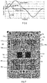
- a substrate 701 of a power semiconductor module 702 with a very compact arrangement is used that, regardless of the compactness, allows for sufficient thermal dissipation, and that is able to include (two) capacitors 703 with larger dimensions due to their higher capacitances.
- the substrate 701 may be a printed circuit board (PCB), direct copper bonding (DCB) substrate or any other substrate with an electrically insulating carrier 704 with an electrically conducting, structured (patterned) layer 705 thereon that interconnects various devices, such as and including switching devices 706, arranged on the substrate 701.
- the arrangement used in this example employs a snubber circuit that includes a stapled construction of two resistors and at least one capacitor close to the switching devices 706 (for interconnections see resistors 106, 107 and capacitor 108 in Figure 1 ).
- the capacitors 703 have two larger parallel surfaces extending between their terminals and are arranged so that the two larger parallel surfaces are in parallel to at least one larger surface of the substrate 701.
- the capacitors 703 are spaced from the substrate 701 via resistors (not shown in Figure 7 ), one at each terminal of the capacitors 703.
- electrically conductive layers or pieces may also be arranged between the capacitor terminals and the resistor(s) and/or between the resistor(s) and the electrically conductive, structured metal layer of the substrate, (e.g., a metal layer pattern).
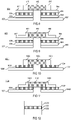
- Figure 8 depicts an exemplary "stacked" snubber circuit 801 which is attached to two segments of a structured metal layer 802.
- the snubber circuit 801 includes electrically conductive, flat first connection layers 803 and 804 (e.g., solder or sheet metal layers) that are each connected to one of the segments of the structured metal layer 802.
- Each of the first connection layers 803 and 804 carries a flat resistive layer 805 and 806, respectively, so that the resistive layers 805 and 806 are connected on one side to the first connection layers 803 and 804, respectively, and on an opposite side to electrically conductive, flat second connection layers 807 and 808, respectively.
- the second connection layers 807 and 808 connect the two terminals of a capacitor 809, which are arranged at two opposite, lateral ends of the capacitor 809, to the second connection layers 807 and 808.
- the two terminals 810 and 811 of the capacitor 809 have the shape of a cuboid end cap and are made from electrically conducting material.
- FIG. 9 Another exemplary "stacked" snubber circuit 901 shown in Figure 9 is identical with the snubber circuit shown in Figure 801 with the exception of the capacitor 809, which is substituted by a capacitor 902.
- the capacitor 902 has, for example, L-shaped terminals which may provide a larger contact area.
- other shapes such as J-shapes are applicable. J-shapes allow the terminals to extend under the capacitor.
- Figure 10 depicts another exemplary "stacked" snubber circuit 1001 which is attached to two segments of a structured metal layer 1002.
- the snubber circuit 1001 includes two, for example flat, resistive layers 1003 and 1004, which are connected on one side to the two segments of a structured metal layer 1002, and on an opposite side to two terminals 1006 and 1007 of a capacitor 1005, which are arranged at two lateral ends of the capacitor 1005.
- the two terminals 1006 and 1007 of the capacitor 1005 have the shape of a cuboid end cap made from electrically conducting material.
- the resistive layers are made from doped semiconductor material.
- FIG. 11 Another exemplary "stacked" snubber circuit 1101 shown in Figure 11 is identical with the snubber circuit shown in Figure 1001 with the exception of the capacitor 1005, which is substituted by a capacitor 1102. Instead of the two terminals of the capacitor 1005 that have the shape of a cuboid end cap, the capacitor 1102 has L-shaped terminals which may provide a larger contact area.
- At least one snubber circuit including the capacitor 703 may be disposed in or near the center of the substrate 701 and/or in close distance to the switching devices 706 to allow for a short interconnection distance to ensure low parasitic inductances, particularly in the connection paths between the switching device and the snubber circuit.
- Figures 8-11 are cross-sections of possible stacked and, thus, very compact snubber circuits applicable as the snubber circuit in the semiconductor module shown in Figure 7 .
- Resistors, resistances or resistive layers used in the stacked snubber circuit may be made from electrically conductive adhesives, sintered (powder) metal or other resistive material with a suitable resistivity.
- the distribution of the power dissipation within the resistor, resistance or resistive layer may be made homogenous, e.g., by employing conductive material with a homogenous resistivity distribution and a sufficient high overall resistivity.
- the resistor, resistance or resistive layer may be formed to be relatively flat, i.e., a large sized base area with a small height relative to the substrate. Resistors, resistances or resistive layers with a short distance in the direction of current flow and a large cross section perpendicular to the direction of current flow are not commonly available.
- the electrically resistive layers may have a height that is equal to or less than 1/5 of the square root of a basic area of the respective electrically resistive layer.
- the electrically resistive layer has a height that is 1/10 of the square root of a basic area of the respective electrically resistive layer.
- Common resistive materials exhibit typically values that are significantly below 0.03 ⁇ m.
- a semiconductor material such as silicon or silicon carbide (e.g., in the form of a semiconductor layer) with adequate doping may be used.
- Such material exhibits a high temperature coefficient of resistance, e.g., due to the temperature dependence of the charge carrier mobility, which however has a minor influence in snubber applications as detailed above.
- resistors, resistances or resistive layers may be or include a doped semiconductor layer 1201 that is laminated on its two major surfaces with metal layers 1202 and 1203 as shown in Figure 12 .
- the metal layers 1202 and 1203 create a type of heat capacitance and may include at least one of copper and aluminum.
- the connection layers described above in connection with Figures 8 and 10 can be designed to (additionally) have the effect of a heat capacitance.
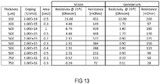
- the semiconductor resistors can be seen as a (semiconductor) material with a homogenous resistivity distribution when neglecting all effects that arise from semiconductor junctions, for example between differently n-doped materials such as N+ (contact), N- (resistive layer) and N+ (further contact), from the edge construction (considering only the active area) of the semiconductor, from the dependency on the mobility of the current density/electric field strength, from the avalanche breakdown field strength, and from the power dissipation.
- Figure 13 is table illustrating multiple implementations of such resistive semiconductor layers for two types of semiconductor materials, e.g., silicon and germanium.
Landscapes
- Engineering & Computer Science (AREA)
- Microelectronics & Electronic Packaging (AREA)
- Computer Hardware Design (AREA)
- Physics & Mathematics (AREA)
- Computing Systems (AREA)
- General Engineering & Computer Science (AREA)
- Mathematical Physics (AREA)
- Power Engineering (AREA)
- Inverter Devices (AREA)
- Power Conversion In General (AREA)
Claims (14)
- Circuit d'amortissement comprenant :un substrat (701) d'amortissement comprenant un support (704) isolant électriquement et une couche (705, 802, 1002) métallique structurée conductrice de l'électricité, qui y est appliquée, la couche métallique structurée conductrice de l'électricité du substrat (701) d'amortissement comprenant deux segments ;deux couches (805, 806, 1003, 1004) résistives électriquement ayant deux extrémités opposées,chaque couche (805, 806, 1003, 1004) résistive étant portée par une extrémité de l'un des deux segments de la couche (705, 802, 1002) métallique structurée conductrice de l'électricité du substrat (701) d'amortissement et y étant connectée électriquement ; etun condensateur (809, 902, 105, 1102) disposé sur les couches (805, 806, 1003, 1004) résistives électriquement et ayant deux bornes (810, 811, 903, 904, 1006, 1007, 1103) à deux extrémités latérales opposées, chaque borne (810, 811, 903, 904, 1006, 1007, 1103) étant connectée électriquement à une autre extrémité de l'une des couches (805, 806, 1003, 1004) résistives électriquement, caractérisé en ce que chacune des deux couches (805, 806, 1003, 1004) résistives électriquement comprend du matériau semiconducteur dopé ou consiste en du matériau semiconducteur dopé.
- Circuit d'amortissement suivant la revendication 1, dans lequel au moins l'un :des premières couches (803, 804) d'interconnexion conductrices électriquement sont disposées entre les deux couches (805, 806) résistives électriquement et les deux segments de la couche (802) métallique structurée conductrice de l'électricité du substrat (701) d'amortissement ; etdes deuxièmes couches (807, 808) d'interconnexion conductrices électriquement sont disposées entre les deux couches (805, 806) (805, 806) résistives électriquement et les deux bornes (810, 811, 903, 904) du condensateur (809, 902).
- Circuit d'amortissement suivant la revendication 2, dans lequel au moins l'une des premières couches (803, 804) d'interconnexion conductrices électriquement et des deuxièmes couches (807, 808) d'interconnexion conductrices électriquement est configurée pour avoir l'effet d'une capacité de chauffage.
- Circuit d'amortissement suivant l'une quelconque des revendications 1 à 3, dans lequel les deux couches (805, 806, 1003, 1004) résistives électriquement comprennent une résistivité de plus de 0,03 Ωm.
- Circuit d'amortissement suivant l'une quelconque des revendications 1 à 4, dans lequel les deux couches (805, 806, 1003, 1004) résistives électriquement ont une hauteur, qui est inférieure ou égale à 1/5 de la racine carrée d'une surface de base de la couche (805, 806, 1003, 1004) résistive électriquement respective.
- Circuit d'amortissement suivant l'une quelconque des revendications 4 ou 5, dans lequel les couches (805, 806, 1003, 1004) résistives électriquement comprennent du matériau ayant une répartition homogène de la résistivité.
- Circuit d'amortissement suivant l'une quelconque des revendications 1 à 6, dans lequel les bornes (810, 811, 903, 904) du condensateur (809, 902, 105, 1102) sont disposées aux extrémités latérales du condensateur (809, 902, 105, 1102) et ont une forme d'une coiffe d'extrémité cuboïde.
- Circuit d'amortissement suivant l'une quelconque des revendications 1 à 6, dans lequel les bornes (810, 811, 903, 904) du condensateur (809, 902, 105, 1102) sont disposées aux extrémités latérales du condensateur (809, 902, 105, 1102) et ont une forme en L.
- Module à semiconducteur de puissance comprenant :un substrat (701) de module comprenant un support (704) isolant électriquement et une couche (705) métallique structurée conductrice de l'électricité, qui y est appliquée, la couche (705) métallique structurée conductrice de l'électricité comprenant des segments multiples ;au moins un dispositif (706) à semiconducteur de coupure disposé sur le substrat (701) du module et connecté électriquement à la couche (705) métallique structurée conductrice de l'électricité ; etau moins un circuit d'amortissement suivant l'une quelconque des revendications 1 à 8 disposé sur le substrat (701) du module et connecté par l'intermédiaire de la couche structurée conductrice de l'électricité du substrat (701) du module au au moins un dispositif (706) à semiconducteur de coupure.
- Module à semiconducteur de puissance suivant la revendication 9, dans lequel le au moins un circuit d'amortissement est disposé à proximité immédiate du au moins un dispositif (706) à semiconducteur de coupure.
- Module à semiconducteur de puissance suivant la revendication 9 ou 10, dans lequel le substrat (701) d'amortissement fait partie du substrat (701) du module.
- Module à semiconducteur de puissance suivant l'une quelconque des revendications 9 à 11, dans lequel le au moins un dispositif (706) à semiconducteur de coupure est un transistor à effet de champ carbure de silicium oxyde métallique.
- Module à semiconducteur de puissance suivant l'une quelconque des revendications 9 à 12, dans lequel le circuit d'amortissement comprend en outre une diode (106) d'amortissement.
- Module à semiconducteur de puissance suivant l'une quelconque des revendications 9 à 13, dans lequel le au moins un circuit d'amortissement est disposé au centre du substrat (701) du module.
Priority Applications (3)
| Application Number | Priority Date | Filing Date | Title |
|---|---|---|---|
| EP19184691.4A EP3761492B1 (fr) | 2019-07-05 | 2019-07-05 | Circuit d'amortissement et module d'alimentation à semi-conducteur ayant un circuit d'amortissement |
| CN202010606317.5A CN112188730B (zh) | 2019-07-05 | 2020-06-29 | 缓冲器电路以及具有缓冲器电路的功率半导体模块 |
| US16/919,518 US11631974B2 (en) | 2019-07-05 | 2020-07-02 | Snubber circuit and power semiconductor module with snubber circuit |
Applications Claiming Priority (1)
| Application Number | Priority Date | Filing Date | Title |
|---|---|---|---|
| EP19184691.4A EP3761492B1 (fr) | 2019-07-05 | 2019-07-05 | Circuit d'amortissement et module d'alimentation à semi-conducteur ayant un circuit d'amortissement |
Publications (2)
| Publication Number | Publication Date |
|---|---|
| EP3761492A1 EP3761492A1 (fr) | 2021-01-06 |
| EP3761492B1 true EP3761492B1 (fr) | 2023-01-04 |
Family
ID=67211529
Family Applications (1)
| Application Number | Title | Priority Date | Filing Date |
|---|---|---|---|
| EP19184691.4A Active EP3761492B1 (fr) | 2019-07-05 | 2019-07-05 | Circuit d'amortissement et module d'alimentation à semi-conducteur ayant un circuit d'amortissement |
Country Status (3)
| Country | Link |
|---|---|
| US (1) | US11631974B2 (fr) |
| EP (1) | EP3761492B1 (fr) |
| CN (1) | CN112188730B (fr) |
Families Citing this family (5)
| Publication number | Priority date | Publication date | Assignee | Title |
|---|---|---|---|---|
| WO2019163205A1 (fr) * | 2018-02-20 | 2019-08-29 | 三菱電機株式会社 | Module de semi-conducteur de puissance et dispositif de conversion d'énergie l'utilisant |
| CN111989850B (zh) * | 2018-06-15 | 2023-09-15 | 株式会社村田制作所 | Cr缓冲元件 |
| CN115732491A (zh) * | 2022-12-05 | 2023-03-03 | 重庆大学 | 一种压电缓冲吸收电路及mosfet功率模块 |
| CN119171560A (zh) * | 2023-06-20 | 2024-12-20 | 宁德时代未来能源(上海)研究院有限公司 | 储能阀子模块和储能系统 |
| DE102024202353A1 (de) * | 2024-03-13 | 2025-09-18 | Volkswagen Aktiengesellschaft | Leistungsmodul |
Citations (1)
| Publication number | Priority date | Publication date | Assignee | Title |
|---|---|---|---|---|
| JP2010123728A (ja) * | 2008-11-19 | 2010-06-03 | Nec Tokin Corp | 固体電解コンデンサ |
Family Cites Families (30)
| Publication number | Priority date | Publication date | Assignee | Title |
|---|---|---|---|---|
| US4916576A (en) * | 1989-02-27 | 1990-04-10 | Fmtt, Inc. | Matrix capacitor |
| US5006822A (en) * | 1990-01-03 | 1991-04-09 | Prabhakara Reddy | Hybrid RF coupling device with integrated capacitors and resistors |
| EP1808954A3 (fr) * | 1991-09-20 | 2008-10-22 | Hitachi, Ltd. | Module IGBT |
| JP3226246B2 (ja) * | 1994-03-11 | 2001-11-05 | 株式会社東芝 | 系統連系用高電圧自励変換装置 |
| JP3263317B2 (ja) * | 1996-06-18 | 2002-03-04 | 株式会社東芝 | スイッチングモジュールおよびモジュールを用いた電力変換器 |
| US7430128B2 (en) * | 2004-10-18 | 2008-09-30 | E.I. Du Pont De Nemours And Company | Capacitive/resistive devices, organic dielectric laminates and printed wiring boards incorporating such devices, and methods of making thereof |
| DE102006017487A1 (de) * | 2006-04-13 | 2007-10-18 | Fraunhofer-Gesellschaft zur Förderung der angewandten Forschung e.V. | Integriertes Beschaltungsbauelement auf Halbleiterbasis zur Schaltentlastung, Spannungsbegrenzung bzw. Schwingungsdämpfung |
| JP4803451B2 (ja) * | 2006-12-26 | 2011-10-26 | Tdk株式会社 | 電子部品及びその実装構造 |
| US20080233704A1 (en) * | 2007-03-23 | 2008-09-25 | Honeywell International Inc. | Integrated Resistor Capacitor Structure |
| JP5218541B2 (ja) * | 2010-12-14 | 2013-06-26 | 株式会社デンソー | スイッチングモジュール |
| JP5447603B2 (ja) * | 2011-08-27 | 2014-03-19 | 株式会社デンソー | 電力変換装置 |
| JP5488638B2 (ja) * | 2012-04-11 | 2014-05-14 | 株式会社デンソー | 電力変換装置 |
| JP5860784B2 (ja) * | 2012-09-10 | 2016-02-16 | 日立オートモティブシステムズ株式会社 | パワー半導体モジュール |
| JP5737272B2 (ja) * | 2012-11-14 | 2015-06-17 | トヨタ自動車株式会社 | 半導体装置 |
| JP5558645B1 (ja) * | 2013-10-02 | 2014-07-23 | 三菱電機株式会社 | Crスナバ回路 |
| JP6196931B2 (ja) * | 2014-04-23 | 2017-09-13 | 株式会社豊田中央研究所 | スナバ回路内蔵モジュール |
| US9601920B2 (en) * | 2014-07-10 | 2017-03-21 | Infineon Technologies Ag | Transient voltage protection circuits and devices |
| WO2016067835A1 (fr) * | 2014-10-30 | 2016-05-06 | ローム株式会社 | Module de puissance et circuit de puissance |
| US10680518B2 (en) * | 2015-03-16 | 2020-06-09 | Cree, Inc. | High speed, efficient SiC power module |
| FR3044184B1 (fr) * | 2015-11-23 | 2018-03-23 | IFP Energies Nouvelles | Systeme modulaire de conversion d'une puissance electrique continue en puissance electrique triphasee |
| KR102494751B1 (ko) * | 2015-12-11 | 2023-02-02 | 삼성전자 주식회사 | 가변 저항 메모리 소자 및 그 제조 방법 |
| EP3249686B1 (fr) * | 2016-05-24 | 2025-02-12 | Mitsubishi Electric R&D Centre Europe B.V. | Un module d'alimentation |
| US10761235B2 (en) * | 2016-10-31 | 2020-09-01 | Weishan Han | Applying E-field antennas to resistivity logging tools |
| US10593664B2 (en) * | 2016-12-27 | 2020-03-17 | Infineon Technologies Americas Corp. | Controlled resistance integrated snubber for power switching device |
| JP6513303B2 (ja) * | 2017-02-06 | 2019-05-15 | 三菱電機株式会社 | 電力用半導体モジュールおよび電力変換装置 |
| US10530270B2 (en) * | 2017-12-01 | 2020-01-07 | Qatar University | Modular isolated half-bridge based capacitor-tapped multi-module converter with inherent DC fault segregation capability |
| WO2019244658A1 (fr) * | 2018-06-23 | 2019-12-26 | 株式会社村田製作所 | Module électronique et alimentation électrique à commutation |
| JP6939740B2 (ja) * | 2018-08-24 | 2021-09-22 | 三菱電機株式会社 | 半導体モジュール |
| JP7038632B2 (ja) * | 2018-09-12 | 2022-03-18 | 三菱電機株式会社 | 半導体装置、及び、半導体装置の製造方法 |
| JP7358921B2 (ja) * | 2019-11-08 | 2023-10-11 | 富士電機株式会社 | 半導体モジュール及び半導体モジュールの製造方法 |
-
2019
- 2019-07-05 EP EP19184691.4A patent/EP3761492B1/fr active Active
-
2020
- 2020-06-29 CN CN202010606317.5A patent/CN112188730B/zh active Active
- 2020-07-02 US US16/919,518 patent/US11631974B2/en active Active
Patent Citations (1)
| Publication number | Priority date | Publication date | Assignee | Title |
|---|---|---|---|---|
| JP2010123728A (ja) * | 2008-11-19 | 2010-06-03 | Nec Tokin Corp | 固体電解コンデンサ |
Also Published As
| Publication number | Publication date |
|---|---|
| US20210006062A1 (en) | 2021-01-07 |
| US11631974B2 (en) | 2023-04-18 |
| CN112188730B (zh) | 2024-10-29 |
| CN112188730A (zh) | 2021-01-05 |
| EP3761492A1 (fr) | 2021-01-06 |
Similar Documents
| Publication | Publication Date | Title |
|---|---|---|
| EP3761492B1 (fr) | Circuit d'amortissement et module d'alimentation à semi-conducteur ayant un circuit d'amortissement | |
| US7738226B2 (en) | Integrated snubber device on a semiconductor basis for switching load reduction, voltage limitation and/or oscillation attenuation | |
| JP6245365B2 (ja) | ハーフブリッジパワー半導体モジュール及びその製造方法 | |
| EP2549650A1 (fr) | Procédé de pilotage d'IGBT | |
| JP5277579B2 (ja) | 半導体装置 | |
| JP2014060914A (ja) | コンデンサ・バンク、積層バス・バー、および電源装置 | |
| WO2013027819A1 (fr) | Module semi-conducteur | |
| CN103299544B (zh) | 用于以电子方式控制dc网络的电路装置 | |
| US10530361B2 (en) | Electrical circuit arrangement with an active discharge circuit | |
| US11303201B2 (en) | CR snubber element | |
| CN115498864A (zh) | 包括晶体管和缓冲器的电路、以及半导体器件 | |
| TW201842730A (zh) | 具有保護回授電路之高功率放大器電路 | |
| EP1933383A2 (fr) | Limiteur de tension de diode à carbure de silicone | |
| Konrad et al. | New demands on DC link power capacitors | |
| JP4773172B2 (ja) | 電力用スイッチング素子の電圧検出方法及びこれを用いた電力変換装置 | |
| JP6973954B2 (ja) | 直流遮断装置 | |
| JP5557571B2 (ja) | ダイオードモジュール | |
| CN101199092B (zh) | 开关电路和控制断路器的方法 | |
| JP2020140996A (ja) | 半導体装置 | |
| JP7789360B2 (ja) | パワー半導体スイッチングモジュール | |
| KR102929776B1 (ko) | 반도체 차단기의 서지 전압 저감 장치 및 서지 전압 저감 방법 | |
| Peri et al. | Design and performance evaluation of a general purpose device characterization setup | |
| WO2019163114A1 (fr) | Module d'alimentation et alimentation électrique à découpage | |
| Temple | ThinPak package for power modules and hybrids | |
| JP2007336637A (ja) | 電力変換器 |
Legal Events
| Date | Code | Title | Description |
|---|---|---|---|
| PUAI | Public reference made under article 153(3) epc to a published international application that has entered the european phase |
Free format text: ORIGINAL CODE: 0009012 |
|
| STAA | Information on the status of an ep patent application or granted ep patent |
Free format text: STATUS: THE APPLICATION HAS BEEN PUBLISHED |
|
| AK | Designated contracting states |
Kind code of ref document: A1 Designated state(s): AL AT BE BG CH CY CZ DE DK EE ES FI FR GB GR HR HU IE IS IT LI LT LU LV MC MK MT NL NO PL PT RO RS SE SI SK SM TR |
|
| AX | Request for extension of the european patent |
Extension state: BA ME |
|
| STAA | Information on the status of an ep patent application or granted ep patent |
Free format text: STATUS: REQUEST FOR EXAMINATION WAS MADE |
|
| STAA | Information on the status of an ep patent application or granted ep patent |
Free format text: STATUS: EXAMINATION IS IN PROGRESS |
|
| 17P | Request for examination filed |
Effective date: 20210701 |
|
| RBV | Designated contracting states (corrected) |
Designated state(s): AL AT BE BG CH CY CZ DE DK EE ES FI FR GB GR HR HU IE IS IT LI LT LU LV MC MK MT NL NO PL PT RO RS SE SI SK SM TR |
|
| 17Q | First examination report despatched |
Effective date: 20210809 |
|
| GRAP | Despatch of communication of intention to grant a patent |
Free format text: ORIGINAL CODE: EPIDOSNIGR1 |
|
| STAA | Information on the status of an ep patent application or granted ep patent |
Free format text: STATUS: GRANT OF PATENT IS INTENDED |
|
| INTG | Intention to grant announced |
Effective date: 20220908 |
|
| GRAS | Grant fee paid |
Free format text: ORIGINAL CODE: EPIDOSNIGR3 |
|
| GRAA | (expected) grant |
Free format text: ORIGINAL CODE: 0009210 |
|
| STAA | Information on the status of an ep patent application or granted ep patent |
Free format text: STATUS: THE PATENT HAS BEEN GRANTED |
|
| AK | Designated contracting states |
Kind code of ref document: B1 Designated state(s): AL AT BE BG CH CY CZ DE DK EE ES FI FR GB GR HR HU IE IS IT LI LT LU LV MC MK MT NL NO PL PT RO RS SE SI SK SM TR |
|
| REG | Reference to a national code |
Ref country code: GB Ref legal event code: FG4D |
|
| REG | Reference to a national code |
Ref country code: CH Ref legal event code: EP |
|
| REG | Reference to a national code |
Ref country code: AT Ref legal event code: REF Ref document number: 1542645 Country of ref document: AT Kind code of ref document: T Effective date: 20230115 |
|
| REG | Reference to a national code |
Ref country code: DE Ref legal event code: R096 Ref document number: 602019023876 Country of ref document: DE |
|
| REG | Reference to a national code |
Ref country code: IE Ref legal event code: FG4D |
|
| REG | Reference to a national code |
Ref country code: LT Ref legal event code: MG9D |
|
| REG | Reference to a national code |
Ref country code: NL Ref legal event code: MP Effective date: 20230104 |
|
| REG | Reference to a national code |
Ref country code: AT Ref legal event code: MK05 Ref document number: 1542645 Country of ref document: AT Kind code of ref document: T Effective date: 20230104 |
|
| PG25 | Lapsed in a contracting state [announced via postgrant information from national office to epo] |
Ref country code: NL Free format text: LAPSE BECAUSE OF FAILURE TO SUBMIT A TRANSLATION OF THE DESCRIPTION OR TO PAY THE FEE WITHIN THE PRESCRIBED TIME-LIMIT Effective date: 20230104 |
|
| P01 | Opt-out of the competence of the unified patent court (upc) registered |
Effective date: 20230528 |
|
| PG25 | Lapsed in a contracting state [announced via postgrant information from national office to epo] |
Ref country code: RS Free format text: LAPSE BECAUSE OF FAILURE TO SUBMIT A TRANSLATION OF THE DESCRIPTION OR TO PAY THE FEE WITHIN THE PRESCRIBED TIME-LIMIT Effective date: 20230104 Ref country code: PT Free format text: LAPSE BECAUSE OF FAILURE TO SUBMIT A TRANSLATION OF THE DESCRIPTION OR TO PAY THE FEE WITHIN THE PRESCRIBED TIME-LIMIT Effective date: 20230504 Ref country code: NO Free format text: LAPSE BECAUSE OF FAILURE TO SUBMIT A TRANSLATION OF THE DESCRIPTION OR TO PAY THE FEE WITHIN THE PRESCRIBED TIME-LIMIT Effective date: 20230404 Ref country code: LV Free format text: LAPSE BECAUSE OF FAILURE TO SUBMIT A TRANSLATION OF THE DESCRIPTION OR TO PAY THE FEE WITHIN THE PRESCRIBED TIME-LIMIT Effective date: 20230104 Ref country code: LT Free format text: LAPSE BECAUSE OF FAILURE TO SUBMIT A TRANSLATION OF THE DESCRIPTION OR TO PAY THE FEE WITHIN THE PRESCRIBED TIME-LIMIT Effective date: 20230104 Ref country code: HR Free format text: LAPSE BECAUSE OF FAILURE TO SUBMIT A TRANSLATION OF THE DESCRIPTION OR TO PAY THE FEE WITHIN THE PRESCRIBED TIME-LIMIT Effective date: 20230104 Ref country code: ES Free format text: LAPSE BECAUSE OF FAILURE TO SUBMIT A TRANSLATION OF THE DESCRIPTION OR TO PAY THE FEE WITHIN THE PRESCRIBED TIME-LIMIT Effective date: 20230104 Ref country code: AT Free format text: LAPSE BECAUSE OF FAILURE TO SUBMIT A TRANSLATION OF THE DESCRIPTION OR TO PAY THE FEE WITHIN THE PRESCRIBED TIME-LIMIT Effective date: 20230104 |
|
| PG25 | Lapsed in a contracting state [announced via postgrant information from national office to epo] |
Ref country code: SE Free format text: LAPSE BECAUSE OF FAILURE TO SUBMIT A TRANSLATION OF THE DESCRIPTION OR TO PAY THE FEE WITHIN THE PRESCRIBED TIME-LIMIT Effective date: 20230104 Ref country code: PL Free format text: LAPSE BECAUSE OF FAILURE TO SUBMIT A TRANSLATION OF THE DESCRIPTION OR TO PAY THE FEE WITHIN THE PRESCRIBED TIME-LIMIT Effective date: 20230104 Ref country code: IS Free format text: LAPSE BECAUSE OF FAILURE TO SUBMIT A TRANSLATION OF THE DESCRIPTION OR TO PAY THE FEE WITHIN THE PRESCRIBED TIME-LIMIT Effective date: 20230504 Ref country code: GR Free format text: LAPSE BECAUSE OF FAILURE TO SUBMIT A TRANSLATION OF THE DESCRIPTION OR TO PAY THE FEE WITHIN THE PRESCRIBED TIME-LIMIT Effective date: 20230405 Ref country code: FI Free format text: LAPSE BECAUSE OF FAILURE TO SUBMIT A TRANSLATION OF THE DESCRIPTION OR TO PAY THE FEE WITHIN THE PRESCRIBED TIME-LIMIT Effective date: 20230104 |
|
| REG | Reference to a national code |
Ref country code: DE Ref legal event code: R097 Ref document number: 602019023876 Country of ref document: DE |
|
| PG25 | Lapsed in a contracting state [announced via postgrant information from national office to epo] |
Ref country code: SM Free format text: LAPSE BECAUSE OF FAILURE TO SUBMIT A TRANSLATION OF THE DESCRIPTION OR TO PAY THE FEE WITHIN THE PRESCRIBED TIME-LIMIT Effective date: 20230104 Ref country code: RO Free format text: LAPSE BECAUSE OF FAILURE TO SUBMIT A TRANSLATION OF THE DESCRIPTION OR TO PAY THE FEE WITHIN THE PRESCRIBED TIME-LIMIT Effective date: 20230104 Ref country code: EE Free format text: LAPSE BECAUSE OF FAILURE TO SUBMIT A TRANSLATION OF THE DESCRIPTION OR TO PAY THE FEE WITHIN THE PRESCRIBED TIME-LIMIT Effective date: 20230104 Ref country code: DK Free format text: LAPSE BECAUSE OF FAILURE TO SUBMIT A TRANSLATION OF THE DESCRIPTION OR TO PAY THE FEE WITHIN THE PRESCRIBED TIME-LIMIT Effective date: 20230104 Ref country code: CZ Free format text: LAPSE BECAUSE OF FAILURE TO SUBMIT A TRANSLATION OF THE DESCRIPTION OR TO PAY THE FEE WITHIN THE PRESCRIBED TIME-LIMIT Effective date: 20230104 |
|
| PLBE | No opposition filed within time limit |
Free format text: ORIGINAL CODE: 0009261 |
|
| STAA | Information on the status of an ep patent application or granted ep patent |
Free format text: STATUS: NO OPPOSITION FILED WITHIN TIME LIMIT |
|
| PG25 | Lapsed in a contracting state [announced via postgrant information from national office to epo] |
Ref country code: SK Free format text: LAPSE BECAUSE OF FAILURE TO SUBMIT A TRANSLATION OF THE DESCRIPTION OR TO PAY THE FEE WITHIN THE PRESCRIBED TIME-LIMIT Effective date: 20230104 |
|
| 26N | No opposition filed |
Effective date: 20231005 |
|
| PG25 | Lapsed in a contracting state [announced via postgrant information from national office to epo] |
Ref country code: SI Free format text: LAPSE BECAUSE OF FAILURE TO SUBMIT A TRANSLATION OF THE DESCRIPTION OR TO PAY THE FEE WITHIN THE PRESCRIBED TIME-LIMIT Effective date: 20230104 |
|
| PG25 | Lapsed in a contracting state [announced via postgrant information from national office to epo] |
Ref country code: MC Free format text: LAPSE BECAUSE OF FAILURE TO SUBMIT A TRANSLATION OF THE DESCRIPTION OR TO PAY THE FEE WITHIN THE PRESCRIBED TIME-LIMIT Effective date: 20230104 |
|
| PG25 | Lapsed in a contracting state [announced via postgrant information from national office to epo] |
Ref country code: MC Free format text: LAPSE BECAUSE OF FAILURE TO SUBMIT A TRANSLATION OF THE DESCRIPTION OR TO PAY THE FEE WITHIN THE PRESCRIBED TIME-LIMIT Effective date: 20230104 |
|
| REG | Reference to a national code |
Ref country code: CH Ref legal event code: PL |
|
| REG | Reference to a national code |
Ref country code: BE Ref legal event code: MM Effective date: 20230731 |
|
| PG25 | Lapsed in a contracting state [announced via postgrant information from national office to epo] |
Ref country code: LU Free format text: LAPSE BECAUSE OF NON-PAYMENT OF DUE FEES Effective date: 20230705 |
|
| GBPC | Gb: european patent ceased through non-payment of renewal fee |
Effective date: 20230705 |
|
| PG25 | Lapsed in a contracting state [announced via postgrant information from national office to epo] |
Ref country code: LU Free format text: LAPSE BECAUSE OF NON-PAYMENT OF DUE FEES Effective date: 20230705 |
|
| REG | Reference to a national code |
Ref country code: IE Ref legal event code: MM4A |
|
| PG25 | Lapsed in a contracting state [announced via postgrant information from national office to epo] |
Ref country code: GB Free format text: LAPSE BECAUSE OF NON-PAYMENT OF DUE FEES Effective date: 20230705 Ref country code: CH Free format text: LAPSE BECAUSE OF NON-PAYMENT OF DUE FEES Effective date: 20230731 |
|
| PG25 | Lapsed in a contracting state [announced via postgrant information from national office to epo] |
Ref country code: IT Free format text: LAPSE BECAUSE OF FAILURE TO SUBMIT A TRANSLATION OF THE DESCRIPTION OR TO PAY THE FEE WITHIN THE PRESCRIBED TIME-LIMIT Effective date: 20230104 Ref country code: FR Free format text: LAPSE BECAUSE OF NON-PAYMENT OF DUE FEES Effective date: 20230731 Ref country code: BE Free format text: LAPSE BECAUSE OF NON-PAYMENT OF DUE FEES Effective date: 20230731 |
|
| PG25 | Lapsed in a contracting state [announced via postgrant information from national office to epo] |
Ref country code: IE Free format text: LAPSE BECAUSE OF NON-PAYMENT OF DUE FEES Effective date: 20230705 |
|
| PG25 | Lapsed in a contracting state [announced via postgrant information from national office to epo] |
Ref country code: IE Free format text: LAPSE BECAUSE OF NON-PAYMENT OF DUE FEES Effective date: 20230705 |
|
| PG25 | Lapsed in a contracting state [announced via postgrant information from national office to epo] |
Ref country code: BG Free format text: LAPSE BECAUSE OF FAILURE TO SUBMIT A TRANSLATION OF THE DESCRIPTION OR TO PAY THE FEE WITHIN THE PRESCRIBED TIME-LIMIT Effective date: 20230104 |
|
| PG25 | Lapsed in a contracting state [announced via postgrant information from national office to epo] |
Ref country code: BG Free format text: LAPSE BECAUSE OF FAILURE TO SUBMIT A TRANSLATION OF THE DESCRIPTION OR TO PAY THE FEE WITHIN THE PRESCRIBED TIME-LIMIT Effective date: 20230104 |
|
| PG25 | Lapsed in a contracting state [announced via postgrant information from national office to epo] |
Ref country code: CY Free format text: LAPSE BECAUSE OF FAILURE TO SUBMIT A TRANSLATION OF THE DESCRIPTION OR TO PAY THE FEE WITHIN THE PRESCRIBED TIME-LIMIT; INVALID AB INITIO Effective date: 20190705 |
|
| PG25 | Lapsed in a contracting state [announced via postgrant information from national office to epo] |
Ref country code: HU Free format text: LAPSE BECAUSE OF FAILURE TO SUBMIT A TRANSLATION OF THE DESCRIPTION OR TO PAY THE FEE WITHIN THE PRESCRIBED TIME-LIMIT; INVALID AB INITIO Effective date: 20190705 |
|
| PGFP | Annual fee paid to national office [announced via postgrant information from national office to epo] |
Ref country code: DE Payment date: 20250915 Year of fee payment: 7 |
|
| PG25 | Lapsed in a contracting state [announced via postgrant information from national office to epo] |
Ref country code: TR Free format text: LAPSE BECAUSE OF FAILURE TO SUBMIT A TRANSLATION OF THE DESCRIPTION OR TO PAY THE FEE WITHIN THE PRESCRIBED TIME-LIMIT Effective date: 20230104 |