EP3761584A1 - Kommunikationssystem mit verwendung von drahtgebundener übertragungsleitung und mehrträgermodulation - Google Patents
Kommunikationssystem mit verwendung von drahtgebundener übertragungsleitung und mehrträgermodulation Download PDFInfo
- Publication number
- EP3761584A1 EP3761584A1 EP19768160.4A EP19768160A EP3761584A1 EP 3761584 A1 EP3761584 A1 EP 3761584A1 EP 19768160 A EP19768160 A EP 19768160A EP 3761584 A1 EP3761584 A1 EP 3761584A1
- Authority
- EP
- European Patent Office
- Prior art keywords
- sub
- carrier
- sinr
- mcs
- carriers
- Prior art date
- Legal status (The legal status is an assumption and is not a legal conclusion. Google has not performed a legal analysis and makes no representation as to the accuracy of the status listed.)
- Ceased
Links
- 230000005540 biological transmission Effects 0.000 title claims abstract description 211
- 238000004891 communication Methods 0.000 title claims abstract description 137
- 239000000969 carrier Substances 0.000 claims description 78
- 238000009825 accumulation Methods 0.000 claims description 6
- 238000000034 method Methods 0.000 description 61
- 230000008569 process Effects 0.000 description 52
- 230000003044 adaptive effect Effects 0.000 description 34
- 238000010586 diagram Methods 0.000 description 28
- 230000006870 function Effects 0.000 description 24
- 238000000605 extraction Methods 0.000 description 18
- 230000008054 signal transmission Effects 0.000 description 5
- 239000000284 extract Substances 0.000 description 4
- 230000010363 phase shift Effects 0.000 description 4
- 238000001228 spectrum Methods 0.000 description 4
- 239000000758 substrate Substances 0.000 description 4
- XLYOFNOQVPJJNP-UHFFFAOYSA-N water Substances O XLYOFNOQVPJJNP-UHFFFAOYSA-N 0.000 description 4
- 230000033228 biological regulation Effects 0.000 description 3
- 230000006978 adaptation Effects 0.000 description 2
- 230000008859 change Effects 0.000 description 2
- 230000004044 response Effects 0.000 description 2
- 239000000470 constituent Substances 0.000 description 1
- 230000007423 decrease Effects 0.000 description 1
- 230000006866 deterioration Effects 0.000 description 1
- 230000000694 effects Effects 0.000 description 1
- 238000009434 installation Methods 0.000 description 1
- 239000004973 liquid crystal related substance Chemical group 0.000 description 1
- 238000012986 modification Methods 0.000 description 1
- 230000004048 modification Effects 0.000 description 1
- 230000008707 rearrangement Effects 0.000 description 1
- 238000006467 substitution reaction Methods 0.000 description 1
Images




Classifications
-
- H—ELECTRICITY
- H04—ELECTRIC COMMUNICATION TECHNIQUE
- H04L—TRANSMISSION OF DIGITAL INFORMATION, e.g. TELEGRAPHIC COMMUNICATION
- H04L1/00—Arrangements for detecting or preventing errors in the information received
- H04L1/0001—Systems modifying transmission characteristics according to link quality, e.g. power backoff
- H04L1/0002—Systems modifying transmission characteristics according to link quality, e.g. power backoff by adapting the transmission rate
- H04L1/0003—Systems modifying transmission characteristics according to link quality, e.g. power backoff by adapting the transmission rate by switching between different modulation schemes
- H04L1/0005—Systems modifying transmission characteristics according to link quality, e.g. power backoff by adapting the transmission rate by switching between different modulation schemes applied to payload information
-
- H—ELECTRICITY
- H04—ELECTRIC COMMUNICATION TECHNIQUE
- H04L—TRANSMISSION OF DIGITAL INFORMATION, e.g. TELEGRAPHIC COMMUNICATION
- H04L27/00—Modulated-carrier systems
- H04L27/26—Systems using multi-frequency codes
- H04L27/2601—Multicarrier modulation systems
- H04L27/2626—Arrangements specific to the transmitter only
- H04L27/2646—Arrangements specific to the transmitter only using feedback from receiver for adjusting OFDM transmission parameters, e.g. transmission timing or guard interval length
-
- H—ELECTRICITY
- H04—ELECTRIC COMMUNICATION TECHNIQUE
- H04B—TRANSMISSION
- H04B17/00—Monitoring; Testing
- H04B17/30—Monitoring; Testing of propagation channels
- H04B17/309—Measuring or estimating channel quality parameters
- H04B17/336—Signal-to-interference ratio [SIR] or carrier-to-interference ratio [CIR]
-
- H—ELECTRICITY
- H04—ELECTRIC COMMUNICATION TECHNIQUE
- H04B—TRANSMISSION
- H04B3/00—Line transmission systems
- H04B3/02—Details
-
- H—ELECTRICITY
- H04—ELECTRIC COMMUNICATION TECHNIQUE
- H04L—TRANSMISSION OF DIGITAL INFORMATION, e.g. TELEGRAPHIC COMMUNICATION
- H04L1/00—Arrangements for detecting or preventing errors in the information received
- H04L1/0001—Systems modifying transmission characteristics according to link quality, e.g. power backoff
-
- H—ELECTRICITY
- H04—ELECTRIC COMMUNICATION TECHNIQUE
- H04L—TRANSMISSION OF DIGITAL INFORMATION, e.g. TELEGRAPHIC COMMUNICATION
- H04L1/00—Arrangements for detecting or preventing errors in the information received
- H04L1/0001—Systems modifying transmission characteristics according to link quality, e.g. power backoff
- H04L1/0002—Systems modifying transmission characteristics according to link quality, e.g. power backoff by adapting the transmission rate
- H04L1/0003—Systems modifying transmission characteristics according to link quality, e.g. power backoff by adapting the transmission rate by switching between different modulation schemes
-
- H—ELECTRICITY
- H04—ELECTRIC COMMUNICATION TECHNIQUE
- H04L—TRANSMISSION OF DIGITAL INFORMATION, e.g. TELEGRAPHIC COMMUNICATION
- H04L1/00—Arrangements for detecting or preventing errors in the information received
- H04L1/0001—Systems modifying transmission characteristics according to link quality, e.g. power backoff
- H04L1/0009—Systems modifying transmission characteristics according to link quality, e.g. power backoff by adapting the channel coding
- H04L1/0011—Systems modifying transmission characteristics according to link quality, e.g. power backoff by adapting the channel coding applied to payload information
-
- H—ELECTRICITY
- H04—ELECTRIC COMMUNICATION TECHNIQUE
- H04L—TRANSMISSION OF DIGITAL INFORMATION, e.g. TELEGRAPHIC COMMUNICATION
- H04L27/00—Modulated-carrier systems
- H04L27/0008—Modulated-carrier systems arrangements for allowing a transmitter or receiver to use more than one type of modulation
-
- H—ELECTRICITY
- H04—ELECTRIC COMMUNICATION TECHNIQUE
- H04L—TRANSMISSION OF DIGITAL INFORMATION, e.g. TELEGRAPHIC COMMUNICATION
- H04L27/00—Modulated-carrier systems
- H04L27/26—Systems using multi-frequency codes
-
- H—ELECTRICITY
- H04—ELECTRIC COMMUNICATION TECHNIQUE
- H04L—TRANSMISSION OF DIGITAL INFORMATION, e.g. TELEGRAPHIC COMMUNICATION
- H04L27/00—Modulated-carrier systems
- H04L27/26—Systems using multi-frequency codes
- H04L27/2601—Multicarrier modulation systems
-
- H—ELECTRICITY
- H04—ELECTRIC COMMUNICATION TECHNIQUE
- H04W—WIRELESS COMMUNICATION NETWORKS
- H04W52/00—Power management, e.g. Transmission Power Control [TPC] or power classes
- H04W52/04—Transmission power control [TPC]
- H04W52/18—TPC being performed according to specific parameters
- H04W52/24—TPC being performed according to specific parameters using SIR [Signal to Interference Ratio] or other wireless path parameters
- H04W52/241—TPC being performed according to specific parameters using SIR [Signal to Interference Ratio] or other wireless path parameters taking into account channel quality metrics, e.g. SIR, SNR, CIR or Eb/lo
-
- H—ELECTRICITY
- H04—ELECTRIC COMMUNICATION TECHNIQUE
- H04L—TRANSMISSION OF DIGITAL INFORMATION, e.g. TELEGRAPHIC COMMUNICATION
- H04L1/00—Arrangements for detecting or preventing errors in the information received
- H04L1/0001—Systems modifying transmission characteristics according to link quality, e.g. power backoff
- H04L1/0009—Systems modifying transmission characteristics according to link quality, e.g. power backoff by adapting the channel coding
Definitions
- the present invention relates to a communication system using a wired transmission line. More specifically, the present invention relates to a communication system using multi-carrier modulation including a plurality of sub-carriers in a network environment in which a wired transmission line is used.
- the OFDM Orthogonal Frequency-Division Multiplexing
- the OFDM is a transmission technique that divides a communication channel into frequency bands (sub-carriers) each bandwidth of which is the same. Further, the OFDM is known as a technique which realizes both of high noise resistance and high data transmission speed. In Patent Document mentioned below, a technique relating to wireless OFDM is disclosed.
- Transmission properties are generally affected by a noise signal, a transmission distance, a transmitter/receiver performance etc. Nevertheless, in wired communications in a factory automation system and an automotive system, stable and efficient signal transmission properties are required even under harsh transmission environments.
- an automotive system such as a Hybrid Electric Vehicle (HEV) and an Electric Vehicle (EV)
- HEV Hybrid Electric Vehicle
- EV Electric Vehicle
- a high-output electric current flows through wire harnesses connected to an inverter or a motor, and electromagnetic noise that is generated then makes a transmission environment even harsher.
- the so-called "suck out” is known as a deterioration of transmission properties peculiar to wired transmission lines such as wire harnesses.
- Fig. 1 is a diagram illustrating the power spectrum of the OFDM.
- a transmission is performed through a band in which a plurality of sub-carriers with narrow bandwidths are bundled.
- the transmission device transmits transmission data through sub-carriers all having same transmission powers (electric powers). Wider bandwidths for the transmission are provided in accordance with an increase of the number of sub-carriers.
- a frequency property of a wired transmission line e.g. harness, cable
- a power loss in transmission power in the wired transmission line is increased with higher frequency.
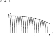
- Fig. 3 is a diagram illustrating the power spectrum of the OFDM using a harness.
- the sub-carrier of the OFDM illustrated in Fig. 1 uses the wired transmission line having the frequency property illustrated in Fig. 2 for a transmission
- the sub-carriers in the high frequencies will have a deteriorated SINR (Signal-to-Interference-Plus-Noise Ratio) as illustrated in Fig. 3 .
- An object of the present invention is to perform a signal transmission adjusted to a transmission property of a wired transmission line in a communication system using the wired transmission line and multi-carrier modulation.
- Fig. 4 is a diagram illustrating a receiving property of a communication device and illustrating the relationship between SINR and BER in regard to BPSK (Binary Phase shift Keying) and QPSK (Quadrature Phase shift Keying).
- a target BER Bit Error Rate
- an SINR satisfying the target BER differs depending on an MCS (Modulation and Coding Scheme). That is, an SINR required to reach the same target BER is higher for QPSK than for BPSK.
- Fig. 5 is a diagram illustrating a receiving property of communication devices A, B and illustrating the relationship between an SINR and a BER in regard to the communication devices A, B.
- the communication devices have different receiving properties. That is, even in a case where BPSK is used as a Modulation Coding Scheme for both of the communication devices A, B, the SINR required to reach the same target BER is higher for the communication device B than for the communication device A. This is because the receiving property is also affected by a noise value generated from the communication device itself.
- Fig. 6 is a diagram illustrating the relationship between SINR and BER in regard to the communication devices A, B.
- the BER of the communication device A does not only reach the target BER in the BPSK transmission but also reaches the target BER in the QPSK transmission.
- the BER of the communication device B does not reach the target BER in the QPSK transmission.
- BPSK is selected based on the communication device B having a low receiving property for the communication between the communication devices X, A and the communication between the communication devices X, B. That is, although QPSK can be used for the communication with the communication device A, the communication device X performs communication using the BPSK in accordance with the communication device B having a low receiving property.
- An incidental object of the present embodiment is to effectively use a receiving property of each communication device in a communication system using a wired transmission line and multi-carrier modulation.
- a communication system that uses a wired transmission line and multi-carrier modulation includes a transmitting device and a receiving device that are connected to each other through the wired transmission line, wherein the receiving device includes an estimator that estimates a first SINR (Signal-to-Interference-Plus-Noise Ratio) of a first sub-carrier and a second SINR of a second sub-carrier, the transmitting device includes a power adjustor that boosts a transmission power for the first sub-carrier such that an SINR of the first sub-carrier reaches a first SINR threshold corresponding to a first MCS (Modulation and Coding Scheme) that is larger than the first SINR, and backs off a transmission power for the second sub-carrier such that an SINR of the second sub-carrier is lowered to a second SINR threshold corresponding to a second MCS that is smaller than the second SINR, and the transmitting device allocates the first MCS to the first sub-carrier.
- SINR Signal-to-Interference-Plus
- an SINR threshold refers to an SINR threshold for BPSK, an SINR threshold for QPSK and the like illustrated in Fig. 18 .
- Each MCS such as BPSK and QPSK has a range of SINR in which an expected BER can be obtained in a case where each MCS is allocated.
- the range of SINR in which the expected BER is obtained in a case where BPSK is allocated in Fig. 18 is between the SINR threshold for BPSK and the SINR threshold for QPSK.
- the SINR threshold corresponding to each MCS represents a lower limit of the range.
- a signal transmission adjusted to the transmission property of the wired transmission line can be carried out.
- the power adjustor may back off the transmission power for the second sub-carrier and then boost the transmission power for the first sub-carrier, thereby allocating the backed-off transmission power for the second sub-carrier to the first sub-carrier.
- the transmission power that has been backed off for the second sub-carrier can be effectively used.
- the power adjustor may back off transmission powers for a plurality of the second sub-carriers, then accumulate the backed-off transmission powers for the plurality of the second sub-carriers and boost transmission powers for one or a plurality of the first sub-carriers, thereby allocating an accumulation value of the backed off transmission powers for the plurality of the second sub-carriers to the one or plurality of the first sub-carriers.
- the transmission power that has been backed off for the second sub-carrier can be effectively used.
- the transmission power can be effectively used in the range of the regulation of a total transmission power.
- the MCS may include at least one modulation and coding scheme selected from a group consisting of 256QAM, 64QAM, 16QAM, QPSK and BPSK.
- the receiving device may include an allocator that allocates the MCS which satisfies a target Bit Error Rate (BER) to each sub-carrier based on an SINR estimated in regard to each sub-carrier, and a transmitter that transmits an allocation information of the MCS that is allocated to each sub-carrier to the transmitting device.
- BER Bit Error Rate
- the transmitting device may dynamically boost the transmission power for the first sub-carrier.
- a transmission power can be dynamically adjusted in accordance with a transmission property.
- the transmitting device may dynamically back off the transmission power for the second sub-carrier.
- a transmission power can be dynamically adjusted in accordance with a transmission property.
- the wired transmission line, the receiving device and the transmitting device are provided in an automobile or a vehicle with a motor.
- vehicle system using multi-carrier modulation for example, a signal transmission adjusted to a transmission property of the wired transmission line can be carried out.
- the present invention enables the signal transmission adjusted to the transmission property of the wired transmission line in the communication system using the wired transmission line and the multi-carrier modulation.
- a communication system of the present embodiment is a communication system that uses a wired transmission line and multi-carrier modulation.
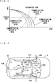
- Fig. 7 is a diagram illustrating a vehicle 5 in which the communication system 50 of the present embodiment is provided.
- the communication system 50 includes Electronic Control Units (ECU) 51A, 51B, camera units 52A, 52B, 52C, 52D, liquid crystal units 53A, 53B, 53C and speaker units 54A, 54B.
- ECU Electronic Control Units
- each of the units 51A, 51B, 52A to 52D, 53A to 53C, 54A, 54B is all connected by the wired transmission line 101.
- an Ethernet cable using STP or UTP based on IEEE 802.3 standard is used as the wired transmission line 101.
- each of the units 51A, 51B, 52A to 52D, 53A to 53C, 54A, 54B includes an OFDM communication device that uses an OFDM (orthogonal frequency-division multiplexing) transmission technique for performing multi-carrier modulation.
- Fig. 8 is a diagram illustrating the communication between the electronic control unit 51A and the camera unit 52A in the communication system 50 according to the present embodiment.
- the electronic control unit 51A includes an ECU substrate 511.
- the OFDM communication device 100 is mounted on the ECU substrate 511.
- the camera unit 52A includes a camera control substrate 521.
- the OFDM communication device 100 is mounted on the camera control substrate 521.
- the electronic control unit 51A and the camera unit 52A respectively include the OFDM communication devices 100.
- the electronic control unit 51A and the camera unit 52A are connected to each other by the wired transmission line 101. All of the other units illustrated in Fig. 7 also include the OFDM communication devices 100 and perform an OFDM transmission through the wired transmission line 101.
- the communication system 50 of the present embodiment uses the wired transmission line 101 and the multi-carrier modulation.
- the communication system 50 of the present embodiment uses the OFDM communication in a vehicle network.
- an OFDM communication device 100 that operates as a receiving device in the present embodiment transmits a difference information with respect to an SINR threshold (Signal-to-Interference-Plus-Noise Ratio) and an MCS (Modulation and Coding Scheme) allocation information to an OFDM communication device 100 that operates as a transmitting device through the wired transmission line 101.
- the OFDM communication device 100 that operates as the transmitting device adjusts a transmission power for each sub-carrier based on the received difference information with respect to an SINR threshold. Further, the OFDM communication device 100 that operates as the transmitting device allocates a designated MCS to each sub-carrier based on the received MCS allocation information.
- Fig. 9 is a block diagram of the OFDM communication device 100 used in the communication system 50 according to the embodiment.
- the OFDM communication device 100 is connected to a counter device (not shown) through the wired transmission line 101.
- the counter device has the configuration and functions similar to those of the OFDM communication device 100. That is, the two OFDM communication devices 100 communicate with each other as illustrated in Fig. 8 .
- the OFDM communication device 100 includes a hybrid unit 102, a demodulator 103, an OFDM data extractor 104, a frame data extractor 105, a transmission power/MCS control unit 106, a power adjustment/MCS allocation information extraction unit 107, an SINR analysis/Adaptive modulation control unit 108, a frame data allocator 110, an OFDM data allocator 111, a modulator 112, a timing generator 113 and an upper layer 120.
- These functions 102 to 108, 110 to 113, 120 are constituted by hardware. However, as described below, part or all of these functions may be realized by software.
- the hybrid unit 102 transmits an OFDM signal to the OFDM communication device 100 which is the counter device through the wired transmission line 101.
- the hybrid unit 102 receives an OFDM signal from the OFDM communication device 100 which is the counter device through the wired transmission line 101.
- the hybrid unit 102 performs a process of superimposing transmission signals and a process of separating receipt signals.
- the demodulator 103 demodulates an OFDM receipt signal from a receipt signal outputted from the hybrid unit 102 based on a timing information generated by the timing generator 113.
- the demodulator 103 demodulates the OFDM receipt signal by performing FFT (Fast Fourier Transform).
- the OFDM data extractor 104 extracts an information of a sub-carrier from the OFDM receipt signal.
- the information of a sub-carrier extracted by the OFDM data extractor 104 is supplied to the SINR analysis/Adaptive modulation control unit 108.
- the frame data extractor 105 extracts frame data and a control frame.
- the frame data extracted from the information of a sub-carrier by the frame data extractor 105 is supplied to the upper layer 120.
- the upper layer 120 receives the frame data and executes various application processes.
- the control frame extracted by the frame data extractor 105 is also supplied to the power adjustment/MCS allocation information extraction unit 107.
- the power adjustment/MCS allocation information extraction unit 107 extracts a difference information with respect to an SINR threshold and an MSC allocation information from the control frame extracted by the frame data extractor 105.
- the difference information with respect to an SINR threshold and the MCS allocation information are the informations stored in the control frame by the OFDM communication device 100 which is the counter device.
- the difference information with respect to an SINR threshold is used for adjustment of a transmission power.
- the process flow of the power adjustment/MCS allocation information extraction unit 107 will be described below in detail.
- the transmission power/MCS control unit 106 controls a transmission power (electric power) for a sub-carrier when frame data is allocated to the sub-carrier, modulated and coded.
- the process flow of the transmission power/MCS control unit 106 will be described below in detail.
- the SINR analysis/Adaptive modulation control unit 108 analyzes an SINR based on an OFDM receipt signal.
- the SINR indicates the quality of a receipt signal and has a property that deteriorates due to interferences and noises.
- the SINR analysis/Adaptive modulation control unit 108 calculates the difference between an SINR threshold and a receipt SINR for each sub-carrier. Further, the SINR analysis/Adaptive modulation control unit 108 determines an MCS to be recommended to the counter communication device (the OFDM communication device 100).
- the MCS to be recommended to the counter communication device (the OFDM communication device 100) is generated as an MCS allocation information.
- the frame data allocator 110 converts the difference information with respect to the SINR threshold and the MCS allocation information into the control data.
- the frame data allocator 110 stores the converted control data in the control frame and allocates the converted control data to a sub-carrier.
- the OFDM data allocator 111 generates an OFDM transmission signal by modulating and coding a sub-carrier information outputted from the frame data allocator 110.
- the modulator 112 modulates the OFDM transmission signal based on the timing information generated by the timing generator 113.
- the modulator 112 modulates the OFDM transmission signal by performing IFFT (Inverse Fast Fourier Transform).
- the modulated OFDM transmission signal is transmitted to the OFDM communication device 100 which is the counter communication terminal through the wired transmission line 101.
- the OFDM communication device 100 which is the counter communication terminal performs the similar process.
- the OFDM communication device 100 which is the counter communication terminal stores the difference information with respect to the SINR threshold and the MCS allocation information in the OFDM transmission signal using the method similar to the above-mentioned method. Further, the OFDM communication device 100 which is the counter communication terminal transmits the OFDM signal storing the difference information with respect to the SINR threshold and the MCS allocation information.
- Fig. 10 is a flowchart illustrating the process flow of the SINR analysis/Adaptive modulation control unit 108.
- the SINR analysis/Adaptive Modulation Control Unit 108 acquires an information of a receipt pilot signal extracted by the OFDM data extractor 104. Then, the SINR analysis/Adaptive modulation control unit 108 estimates a receipt SINR in regard to all sub-carriers based on the receipt pilot signal (step S101). That is, the SINR analysis/Adaptive modulation control unit 108 calculates the estimated SINR in regard to each sub-carrier. A known pilot signal is embedded in each sub-carrier of the OFDM receipt signal. The SINR analysis/Adaptive modulation control unit 108 can estimate receipt SINRs in regard to all sub-carriers by comparing the phase and amplitude of the receipt pilot signal with a known phase and a known amplitude.
- the SINR analysis/Adaptive modulation control unit 108 determines an MCS to be allocated to each sub-carrier based on the known receiving property of the local terminal and the receipt SINR obtained in the step S101 (step 102).
- the SINR analysis/Adaptive modulation control unit 108 has a correspondence table of SINR and a target BER in the local terminal as illustrated in Fig. 4 . This correspondence table represents the receiving property of the local terminal. Further, the target BER is set in advance by the SINR analysis/Adaptive modulation control unit 108.
- the SINR analysis/Adaptive modulation control unit 108 can determine a suitable MCS for each sub-carrier by making reference to the correspondence table and the supplied target BER.
- the MCS which satisfies the target BER on the receipt SINR (estimated SINR) obtained in the step S101 is determined for each sub-carrier.
- the SINR analysis/Adaptive modulation control unit 108 determines the MCS which satisfies the target BER and generates an MCS allocation information for each sub-carrier.
- the SINR analysis/Adaptive modulation control unit 108 calculates the difference between the SINR threshold required for the MCS allocated in the step S102 and the receipt SINR estimated in the step S101 in regard to each sub-carrier. Further, the SINR analysis/Adaptive modulation control unit 108 calculates the difference between the SINR threshold for the MCS that is one level higher than the MCS allocated in the step S102 and the receipt SINR estimated in the step S101 in regard to each sub-carrier (step S103).
- Fig. 14 is a diagram illustrating the gap between the SINR threshold and the receipt SINR for each sub-carrier.
- the receipt SINR is larger than the SINR threshold of 64QAM (64 Quadrature Amplitude Modulation).
- the receipt SINR is lower than the SINR threshold of 256QAM (256 Quadrature Amplitude Modulation). Therefore, the SINR analysis/Adaptive modulation control unit 108 determines the allocation of 64QAM as the MCS of the sub-carriers that belong to the frequency range SA in the step S102.
- the receipt SINR is larger than the SINR threshold of QPSK (Quadrature Phase shift Keying).
- the receipt SINR is smaller than the SINR threshold of 16QAM (16 Quadrature Amplitude Modulation). Therefore, the SINR analysis/Adaptive modulation control unit 108 determines the allocation of QPSK as the MCS of the sub-carriers that belong to the frequency range SB in the step S102.
- BPSK Binary Phase shift Keying
- the SINR analysis/Adaptive modulation control unit 108 calculates the difference between the SINR threshold required for the MCS allocated in the step S102 and the receipt SINR obtained in the step S101.
- the gaps GB in Fig. 14 indicate the differences between the SINR threshold for QPSK allocated to the sub-carriers in the frequency range SB and the receipt SINRs.
- the SINR analysis/Adaptive modulation control unit 108 calculates the difference between the SINR threshold for the MCS that is one level higher than the MCS allocated in the step S102 and the receipt SINR obtained in the step S101.
- the gaps GA in Fig. 14 indicate the differences between the SINR threshold for 256QAM which is one upper MCS level from 64QAM allocated to the sub-carriers in the frequency range SA and the receipt SINRs.
- the differences between the SINR threshold required for the MCS allocated in the step S102 (that is, 64QAM) and the receipt SINRs obtained in the step S101 are not illustrated in regard to the frequency range SA in Fig. 14 , the differences are also obtained similarly in regard to the frequency range SA. Further, while the differences between the SINR threshold for the MCS (that is, 16QAM) that is one level higher than the MCS allocated in the step S102 and the receipt SINRs obtained in the step S101 are not shown in regard to the frequency range SB in Fig. 14 , the differences are obtained similarly in regard to the frequency range SB. That is, in regard to all sub-carriers, the differences between the SINR thresholds required for the allocated MCSs and the receipt SINRs, and the differences between the SINR thresholds for the upper MCS levels and the receipt SINRs are obtained.
- the SINR analysis/Adaptive modulation control unit 108 determines whether calculation of the step S103 has been carried out in regard to all sub-carriers (step S104). In a case where the calculation of the step S103 has not been carried out in regard to all of the sub-carriers, the process returns to the step S101, and the process of the steps S101 to the step S103 is performed in regard to the next sub-carrier. In a case where the calculation in the step S103 has been carried out for all of the sub-carriers, the process proceeds to the step S105 in the SINR analysis/Adaptive modulation control unit 108.
- the SINR analysis/Adaptive modulation control unit 108 supplies the MCS allocation information determined in the step S102 and the difference information in regard to an SINR threshold that is calculated in the step S103 to the frame data allocator 110 as an information of each sub-carrier.
- the difference information in regard to an SINR threshold includes the difference between an SINR threshold required for the allocated MCS and a receipt SINR and the difference between an SINR threshold for the one upper MCS level and a receipt SINR.
- Fig. 11 is a flowchart illustrating the process flow of the frame data allocator 110.
- the frame data allocator 110 acquires the difference information with respect to an SINR threshold and the MCS allocation information from the SINR analysis/Adaptive modulation control unit 108 (step S201).
- the frame data allocator 110 stores the acquired difference information with respect to an SINR threshold and the acquired MCS allocation information in the control frame (step S202).
- the frame data allocator 110 generates frame data that includes the data acquired from the upper layer and the control frame storing the difference information with respect to an SINR threshold and the MCS allocation information.
- the frame data allocator 110 allocates the frame data to each sub-carrier.
- the frame data allocator 110 outputs a sub-carrier information to the OFDM data allocator 111.
- the OFDM allocator 111 modulates and codes each sub-carrier to which the frame data is allocated in a designated MCS level based on the MCS allocation information acquired by the transmission power/MCS control unit 106.
- the difference information with respect to an SINR threshold and the MCS allocation information that are stored in the control frame by the frame data allocator 110 are modulated and coded by the OFDM allocator 111.
- the control frame that is allocated to the sub-carrier, and modulated and coded in the designated MCS level is modulated by the modulator 112 and then transmitted as an OFDM signal.
- the difference information with respect to an SINR threshold and the MCS allocation information are transmitted to the OFDM communication device 100 which functions as the transmitting device from the OFDM communication device 100 which functions as the receiving device.
- the transmitted OFDM signal is received by the OFDM communication device 100 that functions as the transmitting device.
- the control frame included in the OFDM signal is extracted by the frame data extractor 105 and output to the power adjustment/MCS allocation information extraction unit 107.
- the difference information with respect to an SINR threshold that is calculated and the MCS allocation information that is determined by the SINR analysis/Adaptive modulation control unit 108 of the OFDM communication device 100 that functions as the receiving device are extracted by the power adjustment/MCS allocation information extraction unit 107 of the OFDM communication device 100 that functions as the transmitting device.
- Fig. 12 is a flowchart illustrating the process flow of the power adjustment/MCS allocation information extraction unit 107.
- the power adjustment/MCS allocation information extraction unit 107 acquires the control frame that is extracted from the OFDM receipt signal by the frame data extractor 105. Then, the power adjustment/MCS allocation information extraction unit 107 extracts the difference information with respect to an SINR threshold for each sub-carrier and the MCS allocation information of each sub-carrier that are stored by the OFDM communication device 100 which is the counter device from the received control frame (step S301).
- the difference information with respect to an SINR threshold that is calculated and the MCS allocation information that is determined by the SINR analysis/Adaptive modulation control unit 108 which functions as the receiving device is acquired by the OFDM communication device 100 that functions as the transmitting device.
- the power adjustment/MCS allocation information extraction unit 107 supplies the difference information with respect to an SINR threshold and the MCS allocation information that are extracted in the step S301 to the transmission power/MCS control unit 106 (step S302).
- the power adjustment/MCS allocation information extraction unit 107 performs the process of the step S302 for all of the sub-carriers.
- the power adjustment/MCS allocation information extraction unit 107 determines whether the difference informations with respect to SINR threshold and the MCS allocation informations in regard to all of the sub-carriers have been extracted (step S303).
- the process returns to the step S301, and the process of the steps S301 and S302 is repeated for the next sub-carrier.
- the process ends.
- Fig. 13 is a flowchart illustrating the process flow of the transmission power/MCS control unit 106.
- the transmission power/MCS control unit 106 allocates an MCS to each sub-carrier based on the MCS allocation information acquired from the power adjustment/MCS allocation information extraction unit 107. Specifically, the transmission power/MCS control unit 106 supplies the MCS allocation information to the OFDM data allocator 111 and sets an MCS for each sub-carrier. That is, an MCS is allocated to each sub-carrier by the OFDM communication device 100 which functions as the transmitting device in accordance with the MCS allocation information stored by the OFDM communication device 100 that functions as the receiving device.
- the transmission power/MCS control unit 106 provides an instruction in regard to how to allocate the data received from the upper layer to sub-carriers to the frame data allocator 110 (step S401).
- the frame data allocator 110 allocates the data received from the upper layer to each sub-carrier based on the instruction provided by the transmission power/MCS control unit 106.
- the transmission power/MCS control unit 106 determines whether the process of allocating data to all of the sub-carriers has been performed (step S402). In a case where the process of allocating data to all of the sub-carriers has not been completed, the process returns to the step S401, and the process of the step S401 is repeated for the next sub-carrier. In a case where the process of allocating data has been completed for all of the sub-carriers, the process of the transmission power/MCS control unit 106 proceeds to the step S403.
- the transmission power/MCS control unit 106 performs the process of the steps S403 to S406 for each sub-carrier. First, the transmission power/MCS control unit 106 determines whether a low MCS is allocated to a sub-carrier to be processed (step S403).
- a low MCS is an MCS having a low coding rate.
- MCSs include five coding schemes of 256QAM, 64QAM, 16QAM, QPSK and BPSK
- low MCSs indicate QPSK, BPSK and the like.
- Which MCSs are to be classified as the low MCSs may be settable by a user.
- the low MCSs may be determined from among all of the MCSs by the Water Filling Principle.
- the transmission power/MCS control unit 106 backs off the transmission power for the sub-carrier to which a low MCS is allocated by the amount corresponding to the difference information based on the difference information with respect to an SINR threshold that is acquired from the power adjustment/MCS allocation information extraction unit 107 (step S404).
- Fig. 15 is a diagram illustrating SINRs after a transmission power is boosted or backed off for each sub-carrier.
- the transmission power for a sub-carrier in the frequency range SB illustrates the transmission power that is backed off by the amount corresponding to the difference information.
- a sub-carrier in the frequency range SB in Fig. 14 illustrates the sub-carrier before the transmission power is backed off, and a sub-carrier in the frequency range SB in Fig. 15 illustrates an information after a transmission power is backed off.
- a transmission power is backed off to an SINR threshold requested for QPSK which is an allocated MCS. That is, in the state illustrated in Fig.
- a transmission power is wasted in an amount of the difference between an SINR threshold requested for QPSK which is the allocated MCS and a receipt SINR.
- a transmission power is backed off to an SINR threshold requested for QPSK which is the allocated MCS, whereby the transmission power can be distributed to another sub-carrier.
- the transmission power/MCS control unit 106 accumulates the amounts of transmission powers that have been backed off for respective sub-carriers in the step S404 (step S405).
- the transmission power/MCS control unit 106 determines whether the process has ended for all of the sub-carriers (step S406). In a case where the process has not ended for all of the sub-carriers, the process returns to the step S403, and the process for the next sub-carrier is performed. Then, in a case where a low MCS is allocated to the next sub-carrier to be processed, a transmission power is backed off, and the amount of transmission powers that have been backed off in the step S404 are repeatedly accumulated. In a case where the process has been ended for all of the sub-carriers, the process of the transmission power/MCS control unit 106 proceeds to the step S407.
- the transmission power/MCS control unit 106 performs the process of the steps S407 to S409 for each sub-carrier.
- the transmission power/MCS control unit 106 first determines whether a high MCS is allocated to a sub-carrier to be processed (step S407).
- a high MCS refers to an MCS having a high coding rate.
- the MCSs include five coding schemes of 256QAM, 64QAM, 16QAM, QPSK and BPSK, the high MCSs indicate 256QAM, 64QAM, 16QAM and so on. Which MCSs are to be classified as high MCSs may be settable by the user. Alternatively, as described above, high MCSs and low MCSs may be determined from among all of the MCS by the Water Filling Principle.
- the transmission power/MCS control unit 106 distributes the accumulation value of the backed-off transmission powers obtained in the step S405 to the sub-carriers to which high MCSs are allocated (step S408).
- Fig. 15 is a diagram illustrating an SINR after a transmission power is boosted or backed off for each sub-carrier.
- Fig. 15 illustrates the transmission powers corresponding to the difference informations being boosted in regard to the sub-carriers in the frequency range SA.
- Fig. 14 illustrates the SINRs before the transmission powers are boosted for the sub-carriers in the frequency range SA
- Fig. 15 illustrates the SINRs after the transmission powers are boosted for the sub-carriers in the frequency range SA.
- the transmission powers are boosted to the SINR thresholds for 256QAM which is one upper MCS level from 64QAM which is the allocated MCS.
- communication can be carried out at a higher coding rate.
- the transmission power/MCS control unit 106 determines whether the process has been performed for all of the sub-carriers (step S409). In a case where the process has not ended for all of the sub-carriers, the process returns to the step S407, and the process is performed for the next sub-carrier. Then, in a case where a high MCS is allocated to the next sub-carrier to be processed, a transmission power is boosted. In a case where the process has ended for all of the sub-carriers, the process of the transmission power/MCS control unit 106 ends.
- Fig. 16 is a diagram illustrating the allocation of an MCS after a transmission power is boosted or backed off for each sub-carrier.
- 16QAM, QPSK and BPSK are classified as the low MCSs.
- transmission powers are backed off for 16QAM, QPSK and BPSK which are the low MCSs. That is, in regard to 16QAM, QPSK and BPSK, the transmission powers are backed off to the SINR thresholds requested for the allocated MCSs.
- Fig. 16 16QAM, QPSK and BPSK
- the sub-carriers illustrated as being in the frequency range SL are classified as the low MCSs, and the transmission powers corresponding to the difference informations are backed off. Then, the accumulation value of the transmission powers that have been backed off for the sub-carriers illustrated as being in the frequency range SL is allocated to high MCSs.
- part of the sub-carriers to which 16QAM is allocated as illustrated in Fig. 14 is classified as the low MCSs. That is, the boundary between the high MCSs and the low MCSs is provided in the frequency band of the sub-carriers allocated to 16QAM, by way of example.
- the transmission powers are boosted for not less than 64QAM which are the high MCSs.
- the sub-carriers illustrated as being in the frequency range SH are classified as the high MCSs, and the transmission powers corresponding to the difference informations are boosted.
- transmission powers can be boosted for the frequency region SH by the accumulation value of the transmission powers that are backed off for the frequency range SL.
- the transmission power is preferentially allocated may be suitably settable by the user.
- part of the sub-carriers among the sub-carriers to which 16QAM is allocated as illustrated in Fig. 14 is classified as the high MCSs.
- the boundary between the high MCSs and the lower MCSs is provided in the frequency band of the sub-carriers allocated to 16QAM.
- Fig. 19 is a diagram illustrating allocation of the MCSs after the transmission powers of the sub-carriers illustrated in Fig. 14 are boosted or backed off with the boundary set in the frequency range different from the frequency range set in Fig. 16 .
- Fig. 19 is an example where high MCSs and low MCSs are classified based on an originally allocated MCS unit.
- the sub-carriers illustrated as being in the frequency range SL the sub-carriers are classified as the low MCSs, and the transmission powers corresponding to the difference informations are backed off.
- the sub-carriers illustrated as being in the frequency range SH are classified as the high MCSs, and the transmission powers corresponding to the difference informations are boosted.
- the transmission powers are backed off for the sub-carriers to which 16QAM is allocated, that are, the sub-carriers having the SINRs that are the values between the threshold value of 16QAM and the threshold value of 64QAM.
- the process of the flowchart illustrated in Fig. 13 is an inventive example where the transmission powers are boosted or backed off as illustrated in Fig. 19 .
- the transmission power/MCS control unit 106 first determines an MCS for each sub-carrier based on the acquired MCS allocation information. That is, an MCS is determined for each sub-carrier based on the MCS allocation information recommended by the OFDM communication device 100 which functions as the receiving device.
- the transmission power/MCS control unit 106 further boosts the transmission powers for the high MCSs in the step S408.
- the transmission power/MCS control unit 106 allocates an MCS that is one level higher than the MCS that is designated based on the MCS allocation information recommended by the OFDM communication device 100 that functions as the receiving device.
- the gist of the transmission power (electric power) adjustment and adaptive modulation for the sub-carriers in the communication system 50 is as follows.
- the adjustment of transmission powers for sub-carriers (A), SINR adaptation (B) and Dynamic AMC (C), described below, are performed alone or in combination.
- the first (second) SINR threshold for the first (second) MCS is a threshold value of SINR for satisfying a supplied target BER in a case where communication using multi-carrier modulation is carried out in the first (second) MCS.
- the frequency of the first sub-carrier is smaller than that of the second sub-carrier.
- the frequency of the first subcarrier may be larger than that of the second sub-carrier.
- the process of ⁇ d> is performed first, so that a transmission power for the second sub-carrier is backed off. Subsequently, the process of ⁇ c> is performed, so that a transmission power for the first sub-carrier is boosted. At this time, the transmission power for the second sub-carrier is backed off, so that a remaining transmission power is assigned to the first sub-carrier. In a case where the transmission powers for a plurality of sub-carriers that are classified as the second sub-carrier are backed off, the amounts of the transmission powers that are backed off are accumulated. Then, the accumulated transmission power is assigned to the transmission power for the first sub-carrier.
- the transmission powers for the plurality of sub-carriers that are classified as the first sub-carrier are boosted, the accumulated transmission power is assigned to the plurality of these sub-carriers.
- the transmission powers for the low MCSs and the high MCSs can be adjusted in a range of the total transmission power.
- Each MCS needs a lower limit value of SINR (SINR threshold) which achieves a target BER which satisfies a desired transmission property.
- SINR threshold Due to a frequency change of the wired transmission line, SINRs of most of sub-carriers have gaps from SINR thresholds corresponding to applicable MCSs.
- the receiving device detects a gap between an actual SINR and an SINR threshold in regard to each sub-carrier. Then, the transmitting device redistributes the gap in each sub-carrier by boosting or backing off the transmission power so that the high-performance MCS is assigned to a sub-carrier with a high receiving property.
- the applicable MCS is raised to one upper MCS level (e.g. 64QAM to 256QAM). As a result, a high transmission property is achieved.
- which sub-carriers are set as the low MCSs for backing off of transmission powers, and which sub-carriers are set as the high MCSs for boosting of transmission powers may be settable by the user.
- the user sets 256QAM and 64QAM as the high MCSs and sets 16QAM, QPSK and BPSK as the low MCSs.
- the user sets 256QAM, 64QAM and 16QAM as the high MCSs and sets QPSK and BPSK as the low MCSs.
- the user can freely set the boundary between high MCSs and low MCSs.
- the Water Filling Principle that maximizes the channel capacity by allocation of power in correspondence with the reciprocal of the communication quality (an SINR, for example) of each communication device has been known. That is, high MCSs and low MCSs may be determined using the Water Filling Principle such that the transmission efficiency is optimized by assignment of the accumulation value of the transmission powers that are backed off for the low MCSs to the high MCSs.
- MCSs 256QAM, 64QAM, 16QAM, QPSK and BPSK are listed as examples of MCSs in the present embodiment, these are merely examples. The other MCSs may be used as a matter of course.
- the OFDM communication device 100 that functions as the receiving device estimates an SINR for each sub-carrier. Then, the OFDM communication device 100 that functions as the receiving device allocates an MCS that satisfies a target BER for each sub-carrier based on a known receiving property of the local device. The OFDM communication device 100 transmits an MCS allocation information to the OFDM communication device 100 that functions as the transmitting device. Thus, the OFDM communication device 100 that functions as the transmitting device sets an MCS for each sub-carrier based on the received MCS allocation information. Thus, the most suitable MCS corresponding to a receipt SINR is determined among the OFDM communication devices 100.
- the most suitable MCS is determined based on the SINRs among the two OFDM communication devices 100 that actually carry out communication. Even in a case where an OFDM communication device 100 having a poor receiving property and a low SINR is present in the communication system 50, the low SINR does not affect the entire communication system 50.
- the OFDM communication device 100 that functions as the receiving device allocates an appropriate MCS to the boosted or backed-off sub-carrier in response to the receiving property of the local device (OFDM communication device 100) and/or a change of frequency property in the wired transmission line 101. That is, a transmission power for the sub-carrier is boosted or backed off dynamically in response to a transmission line property with the counter device, and a most suitable MCS is set. It is not necessary to adjust devices and transmission schemes after installation of the OFDM communication devices 100, and an effective transmission property is achieved.
- each function element of the OFDM communication device 100 illustrated in Fig. 9 that is, the hybrid unit 102, the demodulator 103, the OFDM data extractor 104, the frame data extractor 105, the transmission power/MCS control unit 106, the power adjustment/MCS allocation information extraction unit 107, the SINR analysis/Adaptive modulation control unit 108, the frame data allocator 110, the OFDM data allocator 111, the modulator 112, a timing generator 113 or the upper layer 120 is constituted by hardware, by way of example. Part or all of the function elements 102 to 108, 110 to 113 and 120 may be realized by software as another configuration.
- the OFDM communication device 100 is constituted by a CPU (Central Processing Unit) 201, a RAM (Random Access Memory) 202, a storage device 203 and an external interface 204 as illustrated in Fig. 17 .
- a CPU Central Processing Unit
- RAM Random Access Memory
- the storage device 203 includes a program 205.
- the program 205 is a program that can implement part or all of the function elements 102 to 108, 110 to 113 and 120 illustrated in Fig. 9 .
- the CPU 201 executes the program 205 using hardware resources such as a RAM 202, thereby being capable of realizing part or all of the function elements 102 to 108, 110 to 113 and 120 illustrated in Fig. 9 .
- a hard disc, a ROM (Read Only Memory) or the like is used as the storage device 203.
- the program 205 may be stored in a storage medium 206 via the external interface 204.
- the OFDM communication device 100 of the present embodiment is provided in the vehicle 5, by way of example. While an object in which the OFDM communication device 100 of the present embodiment is to be provided is not limited in particular, the OFDM communication device 100 is particularly effective in a case where being used in a vehicle that includes a motor such as an engine and generates noise such as an automobile or a vehicle including a motor.
- the OFDM communication device 100 is an example of a transmitting device and a receiving device.
- the SINR analysis/Adaptive modulation control unit 108 is an example of an estimator and an allocator.
- the transmission power/MCS control unit 106 is an example of a power adjustor.
- the frame data allocator 110, the OFDM data allocator 111, the modulator 112 and the hybrid unit 102 are examples of a transmitter.
Landscapes
- Engineering & Computer Science (AREA)
- Signal Processing (AREA)
- Computer Networks & Wireless Communication (AREA)
- Quality & Reliability (AREA)
- Physics & Mathematics (AREA)
- Electromagnetism (AREA)
- Mobile Radio Communication Systems (AREA)
- Transmitters (AREA)
Applications Claiming Priority (2)
| Application Number | Priority Date | Filing Date | Title |
|---|---|---|---|
| US201862642432P | 2018-03-13 | 2018-03-13 | |
| PCT/JP2019/009965 WO2019176931A1 (ja) | 2018-03-13 | 2019-03-12 | 有線伝送路およびマルチキャリア変調を利用する通信システム |
Publications (2)
| Publication Number | Publication Date |
|---|---|
| EP3761584A1 true EP3761584A1 (de) | 2021-01-06 |
| EP3761584A4 EP3761584A4 (de) | 2021-04-21 |
Family
ID=67906734
Family Applications (1)
| Application Number | Title | Priority Date | Filing Date |
|---|---|---|---|
| EP19768160.4A Ceased EP3761584A4 (de) | 2018-03-13 | 2019-03-12 | Kommunikationssystem mit verwendung von drahtgebundener übertragungsleitung und mehrträgermodulation |
Country Status (4)
| Country | Link |
|---|---|
| US (1) | US11356194B2 (de) |
| EP (1) | EP3761584A4 (de) |
| JP (1) | JP7185682B2 (de) |
| WO (1) | WO2019176931A1 (de) |
Families Citing this family (4)
| Publication number | Priority date | Publication date | Assignee | Title |
|---|---|---|---|---|
| WO2020158723A1 (ja) * | 2019-01-31 | 2020-08-06 | 住友電気工業株式会社 | 車載通信システムおよび車載用ケーブル |
| WO2021203032A1 (en) | 2020-04-02 | 2021-10-07 | T-Worx Holdings, LLC | High-throughput data communication for rail-mounted devices |
| EP4020826B1 (de) * | 2020-12-23 | 2026-02-25 | INTEL Corporation | Vorrichtungen und verfahren für spezifische absorptionsratenübertragungssteuerung |
| DE102021133295A1 (de) * | 2021-12-15 | 2023-06-15 | Bayerische Motoren Werke Aktiengesellschaft | Transmitter und Receiver für ein Kommunikationssystem, Kommunikationssystem und Verfahren zum Übermitteln von Informationen |
Family Cites Families (22)
| Publication number | Priority date | Publication date | Assignee | Title |
|---|---|---|---|---|
| US7286609B2 (en) * | 2003-08-08 | 2007-10-23 | Intel Corporation | Adaptive multicarrier wireless communication system, apparatus and associated methods |
| JP4490425B2 (ja) | 2003-09-19 | 2010-06-23 | パナソニック株式会社 | マルチキャリア通信方法、システム及び装置 |
| US20070298728A1 (en) | 2004-09-10 | 2007-12-27 | Matsushita Electric Industrial Co. Ltd. | Wireless Communication Apparatus and Wireless Communication Method |
| KR20060038131A (ko) * | 2004-10-29 | 2006-05-03 | 삼성전자주식회사 | Fh-ofdma 방식을 사용하는 통신 시스템에서상향링크 스케줄링 방법 |
| CN1780278A (zh) * | 2004-11-19 | 2006-05-31 | 松下电器产业株式会社 | 子载波通信系统中自适应调制与编码方法和设备 |
| WO2006064740A1 (ja) | 2004-12-13 | 2006-06-22 | Sharp Kabushiki Kaisha | Ofdm送信装置、ofdm受信装置及びofdm通信方法 |
| JPWO2006080180A1 (ja) | 2005-01-31 | 2008-06-19 | シャープ株式会社 | 無線送信機および無線受信機 |
| US20060209890A1 (en) * | 2005-03-15 | 2006-09-21 | Radiospire Networks, Inc. | System, method and apparatus for placing training information within a digital media frame for wireless transmission |
| US20060268976A1 (en) * | 2005-05-03 | 2006-11-30 | Motorola, Inc. | Method and apparatus for determining channel quality and performing adaptive modulation coding within a multi carrier communication system |
| JP4731991B2 (ja) * | 2005-05-16 | 2011-07-27 | パナソニック株式会社 | マルチキャリア通信装置及びマルチキャリア通信方法 |
| JP4708432B2 (ja) | 2005-08-31 | 2011-06-22 | 三菱電機株式会社 | 電力線搬送通信モデム |
| US8023989B2 (en) * | 2008-08-11 | 2011-09-20 | Chu-Rui Chang | Coordinated power boost and power back-off |
| JP2010124394A (ja) | 2008-11-21 | 2010-06-03 | Toyo Networks & System Integration Co Ltd | 電力線搬送通信装置 |
| US8780728B1 (en) * | 2008-12-22 | 2014-07-15 | Blackberry Limited | Test loading in OFDMA wireless networks |
| US9131395B2 (en) * | 2010-09-08 | 2015-09-08 | Broadcom Corporation | Acknowledgment and/or receiver recovery mechanisms for scheduled responses within multiple user, multiple access, and/or MIMO wireless communications |
| CN102421181B (zh) * | 2011-11-28 | 2014-12-03 | 中国电子科技集团公司第五十四研究所 | 基于认知无线电系统中的子频带功率分配方法 |
| JP5900603B2 (ja) * | 2012-02-28 | 2016-04-06 | 住友電気工業株式会社 | 通信システム、通信装置、給電装置及び車両 |
| JP2014093677A (ja) * | 2012-11-05 | 2014-05-19 | Sharp Corp | 無線通信装置および基地局装置 |
| US9871557B2 (en) * | 2014-07-29 | 2018-01-16 | Cable Television Laboratories, Inc. | Radio frequency leakage detection in a cable plant |
| US10491261B1 (en) * | 2014-11-06 | 2019-11-26 | Abdullah A. Al-Eidan | Multi carrier frequency modulation spread spectrum communication system |
| JP2016192632A (ja) | 2015-03-31 | 2016-11-10 | 株式会社国際電気通信基礎技術研究所 | 無線通信システム、移動局装置および無線通信方法 |
| JP2019153898A (ja) | 2018-03-02 | 2019-09-12 | 富士電機株式会社 | シミュレーション装置 |
-
2019
- 2019-03-12 US US16/979,978 patent/US11356194B2/en active Active
- 2019-03-12 WO PCT/JP2019/009965 patent/WO2019176931A1/ja not_active Ceased
- 2019-03-12 EP EP19768160.4A patent/EP3761584A4/de not_active Ceased
- 2019-03-12 JP JP2020506553A patent/JP7185682B2/ja active Active
Also Published As
| Publication number | Publication date |
|---|---|
| JP7185682B2 (ja) | 2022-12-07 |
| WO2019176931A1 (ja) | 2019-09-19 |
| JPWO2019176931A1 (ja) | 2021-03-11 |
| US20210013993A1 (en) | 2021-01-14 |
| EP3761584A4 (de) | 2021-04-21 |
| US11356194B2 (en) | 2022-06-07 |
Similar Documents
| Publication | Publication Date | Title |
|---|---|---|
| US11356194B2 (en) | Communication system using wired transmission line and multi-carrier modulation | |
| US7929472B2 (en) | Method and apparatus for uplink scheduling in a mobile communication system | |
| KR101524890B1 (ko) | Ofdm 통신 네트워크에서의 피크 전력 대 평균 전력비의 적응적인 저감 방법 및 시스템 | |
| CN101821974B (zh) | 多载波发送装置和多载波接收装置 | |
| JP4872010B2 (ja) | 受信装置および通信方法 | |
| KR100943624B1 (ko) | 직교 주파수 분할 다중 통신 시스템에서 동적 자원 할당장치 및 방법 | |
| US8553642B2 (en) | Method for solving non-controllability of terminal's power spectrum density in OFDMA system | |
| EP2018712B1 (de) | Verkehrslastabhängige leistungszuteilung in einem drahtlosen mehrbenutzer-kommunikationsnetz mit proportionaler fairer einteilung im zeit- und frequenzbereich | |
| EP2178225A1 (de) | Verfahren zur regelung der sendeleistung für eine drahtlose basisstation und drahtlose basisstation | |
| US9295010B2 (en) | Dynamic transmit power and signal shaping | |
| US7411924B2 (en) | Method for allocating subchannels in an OFDMA mobile communication system | |
| EP3107336B1 (de) | Leistungssteuerungsverfahren und -vorrichtung | |
| EP2204028A1 (de) | Kanalabhängige frequenzdomänenplanung in einem orthogonalen frequenzteilungs-multiplex-kommunikationssystem | |
| US8977281B2 (en) | Filter arrangement dependent on occupation of an adjacent band | |
| US20150103751A1 (en) | Dynamic transmit power and signal shaping | |
| CN102843214A (zh) | 无线通信系统中发送/接收数据和控制信息的方法及设备 | |
| JP2003060609A (ja) | 通信方法および通信装置 | |
| KR101002843B1 (ko) | 통신 시스템에서 신호 송수신 장치 및 방법 | |
| KR20080050734A (ko) | 광대역 무선통신시스템의 프레임 구성 장치 및 방법 | |
| KR20070076299A (ko) | 통신 시스템에서 신호 송수신 장치 및 방법 | |
| JP4541210B2 (ja) | マルチキャリア無線通信装置およびそのサブキャリア割り当て方法 | |
| EP2096805A1 (de) | Vorrichtung und Verfahren zur Komplexitätsreduktion | |
| WO2002023847A1 (en) | Method for an adaptive bitloading in an ofdm-based communication system | |
| JP4752523B2 (ja) | 無線通信装置及び方法 | |
| EP2253115B1 (de) | Bandeffizientes verfahren und system zum senden/empfangen eines kommunikationskanals unter verwendung eines kanalbands |
Legal Events
| Date | Code | Title | Description |
|---|---|---|---|
| STAA | Information on the status of an ep patent application or granted ep patent |
Free format text: STATUS: THE INTERNATIONAL PUBLICATION HAS BEEN MADE |
|
| PUAI | Public reference made under article 153(3) epc to a published international application that has entered the european phase |
Free format text: ORIGINAL CODE: 0009012 |
|
| STAA | Information on the status of an ep patent application or granted ep patent |
Free format text: STATUS: REQUEST FOR EXAMINATION WAS MADE |
|
| 17P | Request for examination filed |
Effective date: 20201001 |
|
| AK | Designated contracting states |
Kind code of ref document: A1 Designated state(s): AL AT BE BG CH CY CZ DE DK EE ES FI FR GB GR HR HU IE IS IT LI LT LU LV MC MK MT NL NO PL PT RO RS SE SI SK SM TR |
|
| AX | Request for extension of the european patent |
Extension state: BA ME |
|
| A4 | Supplementary search report drawn up and despatched |
Effective date: 20210322 |
|
| RIC1 | Information provided on ipc code assigned before grant |
Ipc: H04L 27/26 20060101AFI20210316BHEP Ipc: H04L 27/00 20060101ALI20210316BHEP Ipc: H04B 3/02 20060101ALI20210316BHEP Ipc: H04L 1/00 20060101ALI20210316BHEP Ipc: H04W 52/26 20090101ALI20210316BHEP Ipc: H04W 52/34 20090101ALI20210316BHEP |
|
| DAV | Request for validation of the european patent (deleted) | ||
| DAX | Request for extension of the european patent (deleted) | ||
| STAA | Information on the status of an ep patent application or granted ep patent |
Free format text: STATUS: EXAMINATION IS IN PROGRESS |
|
| 17Q | First examination report despatched |
Effective date: 20211119 |
|
| REG | Reference to a national code |
Ref country code: DE Ref legal event code: R003 |
|
| STAA | Information on the status of an ep patent application or granted ep patent |
Free format text: STATUS: THE APPLICATION HAS BEEN REFUSED |
|
| 18R | Application refused |
Effective date: 20230213 |