EP3761876B1 - System zur drainage und analyse von körperflüssigkeiten und zur beurteilung der gesundheit - Google Patents
System zur drainage und analyse von körperflüssigkeiten und zur beurteilung der gesundheit Download PDFInfo
- Publication number
- EP3761876B1 EP3761876B1 EP19781319.9A EP19781319A EP3761876B1 EP 3761876 B1 EP3761876 B1 EP 3761876B1 EP 19781319 A EP19781319 A EP 19781319A EP 3761876 B1 EP3761876 B1 EP 3761876B1
- Authority
- EP
- European Patent Office
- Prior art keywords
- pressure
- urine
- lumen
- drainage
- catheter
- Prior art date
- Legal status (The legal status is an assumption and is not a legal conclusion. Google has not performed a legal analysis and makes no representation as to the accuracy of the status listed.)
- Active
Links
Images






































Classifications
-
- A—HUMAN NECESSITIES
- A61—MEDICAL OR VETERINARY SCIENCE; HYGIENE
- A61B—DIAGNOSIS; SURGERY; IDENTIFICATION
- A61B5/00—Measuring for diagnostic purposes; Identification of persons
- A61B5/20—Measuring for diagnostic purposes; Identification of persons for measuring urological functions restricted to the evaluation of the urinary system
- A61B5/201—Assessing renal or kidney functions
-
- A—HUMAN NECESSITIES
- A61—MEDICAL OR VETERINARY SCIENCE; HYGIENE
- A61B—DIAGNOSIS; SURGERY; IDENTIFICATION
- A61B5/00—Measuring for diagnostic purposes; Identification of persons
- A61B5/01—Measuring temperature of body parts ; Diagnostic temperature sensing, e.g. for malignant or inflamed tissue
-
- A—HUMAN NECESSITIES
- A61—MEDICAL OR VETERINARY SCIENCE; HYGIENE
- A61B—DIAGNOSIS; SURGERY; IDENTIFICATION
- A61B5/00—Measuring for diagnostic purposes; Identification of persons
- A61B5/02—Detecting, measuring or recording for evaluating the cardiovascular system, e.g. pulse, heart rate, blood pressure or blood flow
- A61B5/0205—Simultaneously evaluating both cardiovascular conditions and different types of body conditions, e.g. heart and respiratory condition
-
- A—HUMAN NECESSITIES
- A61—MEDICAL OR VETERINARY SCIENCE; HYGIENE
- A61B—DIAGNOSIS; SURGERY; IDENTIFICATION
- A61B5/00—Measuring for diagnostic purposes; Identification of persons
- A61B5/02—Detecting, measuring or recording for evaluating the cardiovascular system, e.g. pulse, heart rate, blood pressure or blood flow
- A61B5/0205—Simultaneously evaluating both cardiovascular conditions and different types of body conditions, e.g. heart and respiratory condition
- A61B5/02055—Simultaneously evaluating both cardiovascular condition and temperature
-
- A—HUMAN NECESSITIES
- A61—MEDICAL OR VETERINARY SCIENCE; HYGIENE
- A61B—DIAGNOSIS; SURGERY; IDENTIFICATION
- A61B5/00—Measuring for diagnostic purposes; Identification of persons
- A61B5/02—Detecting, measuring or recording for evaluating the cardiovascular system, e.g. pulse, heart rate, blood pressure or blood flow
- A61B5/024—Measuring pulse rate or heart rate
-
- A—HUMAN NECESSITIES
- A61—MEDICAL OR VETERINARY SCIENCE; HYGIENE
- A61B—DIAGNOSIS; SURGERY; IDENTIFICATION
- A61B5/00—Measuring for diagnostic purposes; Identification of persons
- A61B5/02—Detecting, measuring or recording for evaluating the cardiovascular system, e.g. pulse, heart rate, blood pressure or blood flow
- A61B5/024—Measuring pulse rate or heart rate
- A61B5/02405—Determining heart rate variability
-
- A—HUMAN NECESSITIES
- A61—MEDICAL OR VETERINARY SCIENCE; HYGIENE
- A61B—DIAGNOSIS; SURGERY; IDENTIFICATION
- A61B5/00—Measuring for diagnostic purposes; Identification of persons
- A61B5/02—Detecting, measuring or recording for evaluating the cardiovascular system, e.g. pulse, heart rate, blood pressure or blood flow
- A61B5/026—Measuring blood flow
-
- A—HUMAN NECESSITIES
- A61—MEDICAL OR VETERINARY SCIENCE; HYGIENE
- A61B—DIAGNOSIS; SURGERY; IDENTIFICATION
- A61B5/00—Measuring for diagnostic purposes; Identification of persons
- A61B5/02—Detecting, measuring or recording for evaluating the cardiovascular system, e.g. pulse, heart rate, blood pressure or blood flow
- A61B5/026—Measuring blood flow
- A61B5/029—Measuring blood output from the heart, e.g. minute volume
-
- A—HUMAN NECESSITIES
- A61—MEDICAL OR VETERINARY SCIENCE; HYGIENE
- A61B—DIAGNOSIS; SURGERY; IDENTIFICATION
- A61B5/00—Measuring for diagnostic purposes; Identification of persons
- A61B5/03—Measuring fluid pressure within the body other than blood pressure, e.g. cerebral pressure ; Measuring pressure in body tissues or organs
- A61B5/036—Measuring fluid pressure within the body other than blood pressure, e.g. cerebral pressure ; Measuring pressure in body tissues or organs by means introduced into body tracts
-
- A—HUMAN NECESSITIES
- A61—MEDICAL OR VETERINARY SCIENCE; HYGIENE
- A61B—DIAGNOSIS; SURGERY; IDENTIFICATION
- A61B5/00—Measuring for diagnostic purposes; Identification of persons
- A61B5/08—Measuring devices for evaluating the respiratory organs
-
- A—HUMAN NECESSITIES
- A61—MEDICAL OR VETERINARY SCIENCE; HYGIENE
- A61B—DIAGNOSIS; SURGERY; IDENTIFICATION
- A61B5/00—Measuring for diagnostic purposes; Identification of persons
- A61B5/20—Measuring for diagnostic purposes; Identification of persons for measuring urological functions restricted to the evaluation of the urinary system
- A61B5/207—Sensing devices adapted to collect urine
- A61B5/208—Sensing devices adapted to collect urine adapted to determine urine quantity, e.g. flow, volume
-
- A—HUMAN NECESSITIES
- A61—MEDICAL OR VETERINARY SCIENCE; HYGIENE
- A61B—DIAGNOSIS; SURGERY; IDENTIFICATION
- A61B5/00—Measuring for diagnostic purposes; Identification of persons
- A61B5/68—Arrangements of detecting, measuring or recording means, e.g. sensors, in relation to patient
- A61B5/6846—Arrangements of detecting, measuring or recording means, e.g. sensors, in relation to patient specially adapted to be brought in contact with an internal body part, i.e. invasive
- A61B5/6847—Arrangements of detecting, measuring or recording means, e.g. sensors, in relation to patient specially adapted to be brought in contact with an internal body part, i.e. invasive mounted on an invasive device
- A61B5/6852—Catheters
- A61B5/6853—Catheters with a balloon
-
- A—HUMAN NECESSITIES
- A61—MEDICAL OR VETERINARY SCIENCE; HYGIENE
- A61M—DEVICES FOR INTRODUCING MEDIA INTO, OR ONTO, THE BODY; DEVICES FOR TRANSDUCING BODY MEDIA OR FOR TAKING MEDIA FROM THE BODY; DEVICES FOR PRODUCING OR ENDING SLEEP OR STUPOR
- A61M1/00—Suction or pumping devices for medical purposes; Devices for carrying-off, for treatment of, or for carrying-over, body-liquids; Drainage systems
- A61M1/71—Suction drainage systems
- A61M1/74—Suction control
- A61M1/743—Suction control by changing the cross-section of the line, e.g. flow regulating valves
-
- A—HUMAN NECESSITIES
- A61—MEDICAL OR VETERINARY SCIENCE; HYGIENE
- A61M—DEVICES FOR INTRODUCING MEDIA INTO, OR ONTO, THE BODY; DEVICES FOR TRANSDUCING BODY MEDIA OR FOR TAKING MEDIA FROM THE BODY; DEVICES FOR PRODUCING OR ENDING SLEEP OR STUPOR
- A61M1/00—Suction or pumping devices for medical purposes; Devices for carrying-off, for treatment of, or for carrying-over, body-liquids; Drainage systems
- A61M1/90—Negative pressure wound therapy devices, i.e. devices for applying suction to a wound to promote healing, e.g. including a vacuum dressing
- A61M1/96—Suction control thereof
- A61M1/962—Suction control thereof having pumping means on the suction site, e.g. miniature pump on dressing or dressing capable of exerting suction
-
- A—HUMAN NECESSITIES
- A61—MEDICAL OR VETERINARY SCIENCE; HYGIENE
- A61B—DIAGNOSIS; SURGERY; IDENTIFICATION
- A61B2562/00—Details of sensors; Constructional details of sensor housings or probes; Accessories for sensors
- A61B2562/02—Details of sensors specially adapted for in-vivo measurements
- A61B2562/0247—Pressure sensors
-
- A—HUMAN NECESSITIES
- A61—MEDICAL OR VETERINARY SCIENCE; HYGIENE
- A61B—DIAGNOSIS; SURGERY; IDENTIFICATION
- A61B5/00—Measuring for diagnostic purposes; Identification of persons
- A61B5/08—Measuring devices for evaluating the respiratory organs
- A61B5/0816—Measuring devices for examining respiratory frequency
-
- A—HUMAN NECESSITIES
- A61—MEDICAL OR VETERINARY SCIENCE; HYGIENE
- A61B—DIAGNOSIS; SURGERY; IDENTIFICATION
- A61B5/00—Measuring for diagnostic purposes; Identification of persons
- A61B5/103—Measuring devices for testing the shape, pattern, colour, size or movement of the body or parts thereof, for diagnostic purposes
- A61B5/11—Measuring movement of the entire body or parts thereof, e.g. head or hand tremor or mobility of a limb
- A61B5/1118—Determining activity level
-
- A—HUMAN NECESSITIES
- A61—MEDICAL OR VETERINARY SCIENCE; HYGIENE
- A61B—DIAGNOSIS; SURGERY; IDENTIFICATION
- A61B5/00—Measuring for diagnostic purposes; Identification of persons
- A61B5/20—Measuring for diagnostic purposes; Identification of persons for measuring urological functions restricted to the evaluation of the urinary system
-
- A—HUMAN NECESSITIES
- A61—MEDICAL OR VETERINARY SCIENCE; HYGIENE
- A61B—DIAGNOSIS; SURGERY; IDENTIFICATION
- A61B5/00—Measuring for diagnostic purposes; Identification of persons
- A61B5/20—Measuring for diagnostic purposes; Identification of persons for measuring urological functions restricted to the evaluation of the urinary system
- A61B5/202—Assessing bladder functions, e.g. incontinence assessment
-
- A—HUMAN NECESSITIES
- A61—MEDICAL OR VETERINARY SCIENCE; HYGIENE
- A61B—DIAGNOSIS; SURGERY; IDENTIFICATION
- A61B5/00—Measuring for diagnostic purposes; Identification of persons
- A61B5/20—Measuring for diagnostic purposes; Identification of persons for measuring urological functions restricted to the evaluation of the urinary system
- A61B5/207—Sensing devices adapted to collect urine
Definitions
- the present invention relates to the field of medical devices, in particular devices that aid emptying of the bladder, measure urine output and various urine parameters such as oxygen tension, urine conductance and urine specific gravity, monitor renal function, analyze urine parameters, including urine content, including the presence of infection, and track and/or control fluid administration.
- the present invention further relates to medical devices capable of sensing physiologic data based on sensors incorporated into a catheter adapted to reside in any of a urinary tract, gastrointestinal tract, rectal location, pre-peritoneal, pleural space or other body cavity.
- Foley catheter The most common device used to drain the bladder is the Foley catheter. Since its introduction, the design of a flexible tube with an anchoring balloon and eyelets that allow urine to drain through a central lumen has remained largely unchanged. However, it has been found that the current design of Foley catheters can result in a large residual volume remaining in the bladder, for example greater than 50mL in supine patients. See Fallis, Wendy M. Indwelling Foley Catheters Is the Current Design a Source of Erroneous Measurement of Urine Output? Critical Care Nurse 25.2 (2005): 44-51 . In one study, mean residual volume was 96 mL in the ICU and 136 mL in the general ward.
- the urine drainage catheter itself offers an untapped opportunity to detect, collect and analyze additional patient parameters.
- the technology disclosed herein seeks to more effectively drain the bladder, prevent airlocks from forming in the drainage tube and clearing them when they do, and increase the accuracy with which urine output is measured in an automated way.
- the disclosed technology also seeks to incorporate additional measurements of the urine, including oxygen tension, conductance, and specific gravity, gas pressures, turbidity, infection, sediment and others to improve the monitoring of fluid status, renal function, and other important patient parameters.
- One embodiment of a system for analyzing bodily fluids may generally comprise an elongated catheter having an expandable balloon positioned near or at a distal end of the catheter and further defining one or more openings in proximity to the balloon, a venting mechanism coupled to a proximal end of the catheter, the venting mechanism configured to pass air therethrough when negative pressure is applied to the venting mechanism, a first lumen coupled to the venting mechanism and in fluid communication with the one or more openings, a second lumen in fluid communication with the balloon, a reservoir coupled to a proximal end of the first lumen and in fluid communication with the one or more openings, and a controller which is configured to connect to the reservoir and is programmed to control a pressure within the first lumen, wherein the controller is further programmed to monitor a urine output received in the reservoir from a patient and determine an intra-abdominal pressure of the patient based in part upon changes in pressure within the balloon, and wherein the controller is further configured to store patient data.
- Urine specific gravity is a measure of the number and weight of solute particles in urine. Normal ranges are around 1.010 to 1.030. Measurements that are higher than this may indicate dehydration or other conditions. Measurements that are lower than this may indicate fluid overload or other conditions. Measurements may be done by sensors on a Sensing Foley Catheter. Measurement results may indicate increasing (in the case of dehydration) or decreasing (in the case of fluid overload) the infusion rate for a patient. Measurement results may also indicate a change in ventilation parameters or drug infusions etc.
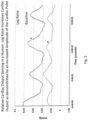
- a Sensing Foley catheter system can measure cardiac activity via pressure sensing in the bladder. Because a Sensing Foley Catheter is capable of measuring respiratory activity as well as cardiac activity, and the frequency of the respiratory rate and the cardiac rate of a patient can be similar to each other, a patient's respiratory measurements can distort the cardiac measurements. To overcome this issue, some embodiments of a controller may pause the respirator at the end of one or more inspiration points, and/or pause the respirator at the end of one or more expiration points (for just a few seconds each time, for example 1 to 3 seconds, or for example, 1 to 4 seconds) so that the cardiac waveform can be captured without respiratory distortion.
- a system for assessing health of a patient may generally comprise a drainage tube configured to be in fluid communication with at least one opening positioned near or at a distal end of a catheter, a pump in fluid communication with the drainage tube and configured to apply a negative pressure to the drainage tube, and a valve configured for unidirectional flow and in fluid communication with the drainage tube.
- a controller may be in communication with the pump, wherein the controller is configured to actuate the pump to apply the negative pressure for clearing an airlock from the drainage tube.
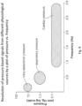
- the profiles need to be sampled at a rate that is sufficient to resolve the inherent frequency of changes in the profile.
- This consideration is informed by the Nyquist-Shannon sampling theorem, which states that a sampling frequency of at least 2B samples/second is required to resolve an event that runs at a frequency of B cycles/second.
- a cardiac rate of 70 beats/minute requires a sampling rate of at least 140 samples/minute to effectively capture the cycle.
- This relationship underlies aspects of the disclosed technology that specify the sampling rate particularly required to capture physiologic pressure cycles such as relative pulmonary tidal volume, cardiac output, relative cardiac output, and absolute cardiac stroke volume.
- Embodiments of the technology include a pressure interface as may be represented by a balloon having either a compliant membrane or a non-compliant membrane.
- the membrane of the balloon Upon expansion of the balloon from a minimal volume to its maximal volume, the membrane of the balloon maintains a level of tautness. Within the limits of compliance of the compliant membrane, an increase in pressure during inflation results in a consequent expansion of volume.
- the balloon on the whole may be considered partially compliant in that its shape responds to spatial constraints that it may encounter upon expansion or inflation, however the balloon does have a preferred or native shape, and such shape preference prevents a level of shape compliance or conformability such as that exhibited by a non-compliant balloon.
- the catheter of the present invention is uniquely suited to the pediatric indication where there is a dire need for more appropriate, less invasive monitoring methods.
- the retention balloon itself can be used as the pressure balloon, in order to minimize the number of required lumens.
- the retention balloon is used in its fully inflated state, and is only used to track macro trends in IAP.
- the retention balloon is only slightly inflated in order to increase balloon sensitivity to small changes in pressure. This embodiment allows for finer measurements of micro parameters, such as heart rate, relative stroke volume, relative cardiac output, respiratory rate, and relative tidal volume.
- a smaller pressure lumen also allows for more space in a larger catheter for other technologies, such as sensors etc.
- the pressure measured within the retention balloon is offset by the pressure required to just inflate the balloon large enough for it to serve as a retention balloon.
- the inflation pressure, and possibly the pressure resulting from the retention balloon being in contact with the inner surface of the bladder needs to be subtracted from the pressure reading. In this way, smaller pressure changes may be tracked similarly to those measured by the separate pressure balloon.
- the inflation pressure offset may be determined by measuring the pressure within the retention balloon when it is first inserted into the patient, or by measuring the retention balloon inflation pressure outside the patient, or by other means.
- the retention balloon may be filled with fluid, air or any other appropriate gas.
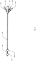
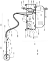
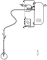
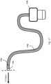
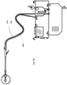
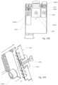
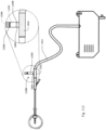
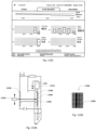
- Sensing Foley catheter 1000 is similar to the sensing Foley catheter shown in Fig. 1 .
- the sensing Foley catheter is shown in use in bladder 1014. Note that several of the ports at the proximal end of the catheter shown in Fig. 1 are combined in the embodiment shown in Fig. 10A .
- Urine drainage tube 1001 is also shown here.
- the urine drainage tube may be combined with the sensing Foley catheter or may be a separate component.
- Urine drainage tube 1001 and/or sensing Foley catheter may also include vent barb (or barb) 1016, or the vent barb may be a separate component.
- Airlock clearing mechanism and fluid collection & analysis system 1002 is also shown here, and is in fluid communication with urine drainage tube 1001 which is in fluid communication with sensing Foley catheter 1000.
- Airlock clearing mechanism and fluid collection & analysis system includes base/controller 1018, fluid collection bag 1020 and reservoir or cassette 1022.
- the combination of the sensing Foley catheter 1000, the urine drainage tube 1001, and the airlock clearing mechanism and fluid collection & analysis system 1002 are also referred to herein as the sensing Foley catheter system.
- the sensing Foley catheter, urine drainage line, and reservoir/cassette may be disposable and may be sold as a unit. This disposable assembly is shown in Fig. 10D, which includes sensing Foley catheter 1000, urine drainage tube 1001 (including vent barb) and reservoir/cassette 1022.
- Vent barb 1016 may include vent, or vents, 1006 as well as urine sampling port 1004.
- vent 1006 is preferably made from a membrane that permits the transmission of gases, but not liquids, such as hydrophobic membranes.
- An example of one such exemplary vent is a PTFE (Polytetrafluoroethylene), ePTFE (Expanded PTFE), or Versapor ® (from Pall Corporation of Port Washington, NY), membrane, although other materials may be used.
- the vent allows air to enter the system when negative pressure is applied to the drainage tube, and may allow air to exit the system when positive pressure is created due to airlocks in the drainage line. Such a mechanism prevents suction trauma, for example at the bladder wall.
- Vents 1006 may incorporate a one-way valve which prevents air from exiting the drainage line, or entering the drainage line.
- a one-way valve is used to prevent air from exiting the drainage line, but allows air to enter the drainage line, via vents 1006. In this manner, the valves also prevent urine from coming into contact with vents 1006.
- Urine drainage tube 1001 may include several lumens, including pressure lumen 1010, temperature lumen 1008, and urine lumen 1012.
- Pressure lumen 1010 is in fluid communication with pressure sensing balloon 108 as well as pressure transducer interface 1026 in controller 1018.
- Temperature lumen 1008 communicates with the temperature sensor (not shown) in the sensing Foley catheter and also temperature connector port 1024 in the controller.
- Urine lumen 1012 is in fluid communication with opening or openings 106 and urine reservoir or cassette 1022.
- Disposable measurement vessel, collection vessel, chamber or cassette component 1022 is designed to fit into cassette mount, base or controller 1018 and to interface with the components of the controller.
- Controller pump interface (behind cassette pump interface 1148) connects to pump 1134 and to cassette pump interface 1148 on the disposable cassette component.
- the pump is designed to create a vacuum inside the cassette component, which is then transferred to the urine drainage lumen in the drainage line.
- the collection vessel/cassette is rigid in order to maintain a constant volume when the pump applies negative pressure.
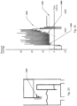
- the level of negative pressure applied may be monitored by a pressure sensor. During clearance of an airlock, the pressure follows a signature curve as shown in Fig. 59 .
- the patient data may be saved to memory, USB, micro-SD card, EPROM card, hard drive, or otherwise.
- the patient data may be transferred wirelessly or by wired connection to another storage device, such as a server on the internet or an intranet.
- Patient data may be anonymized.
- Patient data, such as the patient ID may be stored in an RFID adapter so that data specific to a particular patient is recognized by the controller and associated with the disposable component used by that patient.
- the RFID adapter may be located on the disposable portion of the system, for example, on cassette 1022 or elsewhere where the disposable components interface with the non-disposable components.
- all collected patient data may be stored in an RFID adapter, so that different monitors may be used for the same patient without switching out the disposable portion of the system.
- Urine/fluid drainage bag 1020 includes one way valves 1136 connected to overflow tubing 1138 and outflow tubing 1140 to prevent urine/fluid from exiting the drainage bag once collected. These valves also prevent air from entering the collection vessel 1022 when pump 1134 is pulling vacuum so that the vacuum acts on the drainage tubing and not the bag. In a preferred embodiment, a single valve is used for both the overflow and outflow tubings. Mounting hooks/holes 1102 allow drainage bag 1020 to be removably attached to controller 1018. Vent 1142, which may be a hydrophobic or other vent, allows air or gas to exit the drainage bag, but does not allow fluid to exit the bag.
- Overflow barrier 1137 is shown in collection vessel/reservoir/cassette 1022.
- the overflow barrier is generally at a height above the level at which the controller empties the cassette. For example, if the controller empties the cassette when the fluid volume reaches 50ml, the overflow barrier will reach a height above the level of the 50ml volume.
- the overflow barrier may be about 5-10mm above the level of the emptying volume.
- the overflow barrier may be about 10-20mm above the level of the emptying volume.
- the overflow barrier may be about 20-30mm above the level of the emptying volume.
- the overflow barrier may be about 30-40mm above the level of the emptying volume.
- the patient temperature is measured using the thermistor/temperature sensor in the patient body. This temperature may be passed through the controller to be displayed on a third party device.
- Fig. 10B shows how parallel potentiometers may be used to reduce error in the temperature measurement before it is transferred to an external display or external device.
- the drainage bag may be made out of clear vinyl or other suitable material.
- the one-way valves may be made out of vinyl or other suitable material.
- the hydrophobic vent may be made out of ePTFE, Versapor, or other suitable material.
- the outflow valve may be made out of PVC, PC, or other suitable material.
- Pressure readings from the sensing Foley catheter may be used to trigger the pump and therefore the emptying of the drainage tubing. For example, when pressure sensed in the bladder exceeds a preset number, the pump may engage to move urine more quickly through the drainage tubing.
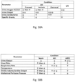
- risk assessments may be determined by the controller and displayed in addition to, or as an alternative to, the Sepsis Index. These include risk assessments of acute kidney injury, urinary tract infection, intra-abdominal hypertension, abdominal compartment syndrome, infection risk, sepsis, ARDS (Acute respiratory distress syndrome) and others.
- Fig. 58A A sample risk algorithm for acute kidney injury, sepsis and acute respiratory distress syndrome is shown in Fig. 58B .
- Measured urine parameters may include conductance, specific gravity, urine output, presence of infection, bacteria, white blood cells, oxygen tension and others.
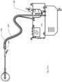
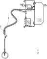
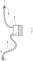
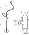
- Fig. 11A shows an embodiment of the sensing Foley catheter system (including airlock clearing mechanism, fluid drainage, collection & analysis system/controller) similar to that shown in Fig. 10A where vent 1180 is located on controller 1018 or reservoir/ cassette 1022, instead of on vent barb (or barb) 1182.
- vent 1180 is in fluid communication with urine drainage lumen 1012 via vent lumen 1184 which fluidly connects to urine lumen 1012 at barb 1182.
- the barb design is simplified and the drainage tubing simply has an additional lumen compared to the embodiment shown in Fig. 10A .
- the vent may be located anywhere in the system and the fluid interface with the urine lumen may be anywhere in the system as well.
- Fig. 11B shows an embodiment of the sensing Foley catheter system similar to that shown in Fig. 11A .
- a gas permeable vent/filter is incorporated into cassette 1022 and/or controller 1018.
- the vent lumen may pass within vent tube 1184 from barb 1182, along drainage tube 1012.
- the vent lumen may end external to the cassette and/or controller, or, as shown here, may pass through the cassette and possibly the controller and incorporate gas permeable vent/filter 1180.
- Fig. 11B also shows valve 1186.
- the valve may be a one-way valve which allows flow of fluid (for example, atmospheric air) to flow through the vent lumen, and into the drainage tube via the barb, or other location along the drainage tube or Foley catheter, or within base/controller 1018.
- the valve prevents fluid, such as urine and/or air, from flowing through the vent tube and possibly reaching the filter.
- the valve may be passive, as shown here, or may be actively controlled by the controller.
- the valve may be anywhere within or along the vent lumen, including in the barb, anywhere along the vent tube, in the cassette, in the controller, or outside of the controller, for example, on the non-patient side of the controller.
- the valve is actively controlled via the controller by controlling the negative pressure in the drainage tube.
- the valve may be opened by the controller pulling a negative pressure within the drainage lumen of the drainage tube, and the valve may be closed by the controller reducing the vacuum applied to the drainage tube (i.e, applying a less negative pressure, applying zero pressure, or applying a slightly positive pressure to the drainage lumen). Since the drainage lumen of the catheter and drainage tube are in fluid communication with the lumen of the vent tube, the negative pressure applied to the drainage tube is also applied to the lumen of the vent tube and the valve opens when the pressure differential across the valve exceeds the valve's crack pressure.
- the valve may be closed again by reducing the vacuum applied to the drainage lumen, and thus reducing the pressure differential across the valve to a pressure below the crack pressure of the valve.
- the controller may actively control the opening and the closing of the valve within the vent tube, even where the valve itself is a passive valve.
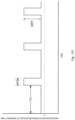
- the controller actively opening the valve may be done periodically, for example, on a regular schedule. This is shown graphically in Fig. 11F .
- the controller may open the valve at least every 30 minutes (represented by T1), may leave the valve open for at least 15 seconds (represented by T2), and may then close the valve for another 30 minutes until the cycle starts again.
- the difference between the vacuum applied to open the valve and the vacuum applied to maintain a closed valve is represented by DIFF in the figure. DIFF is greater than the crack pressure differential of the valve.
- T1 may be at least 60 minutes.
- T1 may be at least 20 minutes.
- T1 may be at least 10 minutes.
- T1 may be at least 5 minutes.
- T2 may be at least 5 seconds.
- T2 may be at least 10 seconds.
- T2 may be at least 20 seconds.
- T2 may be at least 30 seconds.
- Fig. 11F shows the valve close pressure at a negative pressure, however, the valve closed pressure may be zero or may be positive.
- the cycle length may alternatively be variable, where T1 and/or T2 depend on the urine output flow rate.
- the cycle may alternatively be based on the system sensing an airlock in the drainage tube. This can be done by measuring pressure within the system, for example, vacuum pressure within the drainage tube or pressure at the barb.
- valve 1186 may be in place without a filter. In some embodiments, a filter may be between the drainage lumen and valve 1186.
- vent tube 1184 is integrated with drainage tube 1012 along all, or part of the drainage tube's length.
- the valve may be a duckbill valve, an umbrella valve, a ball-valve, a dome valve, a Belleville valve, a cross slit valve, an x-fragm valve or any other valve suitable for medical applications.
- the valve may have a very low crack pressure, or may have a higher crack pressure but will generally be between zero and the magnitude of the negative pressure being pulled by the vacuum pump.
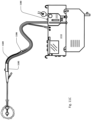
- Fig. 11C shows an embodiment of the sensing Foley catheter system similar to that shown in Fig. 11B .
- the vent tube includes a portion of the lumen with a smaller diameter between the barb and the valve.
- a smaller inner diameter tubing between the barb and the valve creates a column of air between the valve and the barb, which will generally prevent urine from entering the vent tube when the vent tube valve is closed.
- the vent tube valve is open, the fluid flow is general flowing the other way (i.e. into the drainage lumen) which also prevents urine from entering the vent tube.
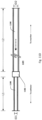
- Fig. 11D shows an example of a vent tube with different diameter sections.
- First section 1188 is the section closest to the patient and has an inner ID of ID1 and a length of L1.
- valve 1186 allows fluid to generally only flow right to left as shown by the dashed arrow.
- Second section 1190 is further from the patient and has an inner ID ID2 and a length L2.
- L1 is less than L2 and ID1 is less than ID2.
- ID1 is less than ID2 but the lengths may vary or may be the same as each other.
- L1 + L2 may be approximately the same length as the drainage tube.
- ID1 may be around 1.8-2.0mm. In some embodiments, ID1 may be around 1.6-1.8mm. In some embodiments, ID1 may be around 1.4-1.6mm. In some embodiments, ID1 may be around 1.2-1.4mm. In some embodiments, ID1 may be around 1.0-1.2mm. In some embodiments, ID1 may be around 0.8-1.0mm. In some embodiments, ID1 may be around 0.5-0.8mm. In some embodiments, ID1 may be around 0.2-5mm. In some embodiments, ID1 may be less than around 1mm. In some embodiments, ID1 may be less than around 2mm. In some embodiments, ID1 may be less than around 3mm. In some embodiments, ID1 may be less than around 4mm. In some embodiments, ID1 may be less than around 2mm. Preferably, ID1 is small enough to hold a siphon for all or part of its length.
- ID2 may be around 1.8-2.0mm. In some embodiments, ID2 may be around 1.6-1.8mm. In some embodiments, ID2 may be around 1.4-1.6mm. In some embodiments, ID2 may be around 1.2-1.4mm. In some embodiments, ID2 may be around 1.0-1.2mm. In some embodiments, ID2 may be around 0.8-1.0mm. In some embodiments, ID2 may be around 0.5-0.8mm. In some embodiments, ID2 may be around 0.2-5mm. In some embodiments, ID2 may be less than around 4mm. In some embodiments, ID2 may be less than around 5mm. In some embodiments, ID2 may be less than around 6mm. In some embodiments, ID2 may be greater than around 2mm. In some embodiments, ID2 may be greater than around 3mm. In some embodiments, ID2 may be greater than around 4mm. In some embodiments, ID2 may be greater than around 5mm. In some embodiments, ID2 may be greater than around 6mm.
- L1 may less than around 5cm. In some embodiments, L1 may less than around 10cm. In some embodiments, L1 may be around 5-10cm. In some embodiments, L1 may be around 10-20cm. In some embodiments, L1 may be around 20-30cm. In some embodiments, L1 may be around 30-50cm. In some embodiments, L1 may be greater than about 50cm. In some embodiments, L1 may be greater than about 1cm. In some embodiments, L1 may be greater than about 2cm. In some embodiments, L1 may be greater than about 5cm. In some embodiments, L1 may be greater than about 10cm.
- L2 may be around 50-150cm.
- ID1 and ID2 may be identical.
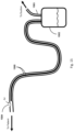
- Fig. 11E shows an embodiment of the catheter system in which vent lumen 1184 is in direct fluid communication with fluid collection bag 1020.
- a controller including sensing functions may or may not be present.
- airlocks are avoided by the vent lumen which uses vent 1142 in the fluid collection bag to vent urine drainage lumen 1012.
- the vent may additionally or alternatively be anywhere along the vent lumen.
- the vent lumen may run part or all the length of the drainage lumen.
- the urine drainage lumen fluidly connects to the drainage bag at connection point 1192, which may include valve 1136.
- the vent lumen connects to the drainage bag at connection point 1194.
- Fluid collection bag 1020 in this embodiment, and potentially other embodiments, may include rigid or semi rigid portion 1196 to ensure that the fluid collection bag does not collapse around connection point 1194.
- This embodiment may or may not include valve 1186.
- Vent tube 1184 may be incorporated into the drainage tube system or may be an add-on piece, which is connected at or near the barb of the Foley catheter and at connection point 1194 of the drainage bag.
- Fig. 12A shows an embodiment of the sensing Foley catheter system similar to that shown in Fig. 10A where, as opposed to the system shown in Fig. 10A , no pressure balloon is utilized. Instead, pressure is measured inside the bladder via the urine lumen (or other lumen) in the sensing Foley catheter.
- the pressure lumen 1202 is connected to the vent 1204, or elsewhere in the system outside the patient, and is, at lease periodically, in fluid communication with the drainage/urine lumen of the catheter.
- the sensing Foley catheter system may be used with any standard Foley catheter. Note that any embodiments of the sensing Foley catheter system may be used with a standard Foley catheter.
- the system shown in Fig. 12A may also be used without pressure lumen 1202, and with a standard Foley catheter, if pressure measurements in the bladder are not desired.
- the sensing Foley system are able to determine intraabdominal pressure with a standard, or off-the-shelf, Foley catheter.
- the controller may be used with a standard Foley catheter and still incorporate IAP measurements into its analysis.
- the controller may cause a pump to introduce an air or gas bubble into the drainage line of a Foley catheter.
- the controller can determine at what point the bubble of gas/air exits the Foley catheter and enters the bladder.
- the pressure required to push a column of fluid, containing a gas bubble, into the drainage line will increase until the bubble exits the drainage line.
- the pressure at which the bubble exits the Foley catheter is equal to the intraabdominal pressure.
- the fluid column may be solid or intermittent.
- the IAP measurement sequence may be performed by the controller on a regular basis. It may be performed before or after airlock clearance has been performed. The IAP measurement may also be done manually, by physically watching the pressure on a gauge, similar to a blood pressure cuff.
- the vent tube may be closed before this type of IAP measurement is performed.
- the gas may be sterile and/or may be sterilized via UV light during transit, for example at the barb area.
- an irrigation lumen may be included in the Foley catheter, or a separate irrigation catheter with an irrigation lumen may be used to irrigate the bladder.
- the controller of the sensing Foley system may communicate with the irrigation pump so that the volume of irrigation fluid may be subtracted from the measured fluid output to accurately determine urine output (which does not include irrigation fluid).
- a specialized clamp may be used to clamp one or more lumens of the drainage tubing without clamping the urine drainage lumen of the drainage tubing.
- the clamp may be configured to align the clamping mechanism with the drainage tubing, for example, to close the pressure lumen, but not the urine drainage lumen of the drainage tubing.
- Fig. 12B shows an embodiment of the sensing Foley catheter system which does not include measuring of IAP or temperature. Note that this embodiment still has the anti-airlock features.
- Fig. 13 shows an embodiment of the sensing Foley catheter system similar to that shown in Fig. 12A .
- valve 1302 may be utilized to periodically close pressure lumen 1202 to the urine drainage lumen.
- the valve can be opened, by the controller or manually, when a pressure measurement is taken, and closed, again by the controller or manually, when a bladder pressure reading is not needed.
- Figs. 10A , 10C , 11 and 12 show embodiments of the sensing Foley catheter system which include a vent near the patient end of the drainage tube that allows air to enter the drainage tube if negative pressure is created either due to a siphon in the drainage tube or due to the pumping mechanism or both. Without a vent/filter, such negative pressure can lead to suction trauma, such as trauma caused to the mucosal lining of the bladder. Note that these embodiments are different than devices where the vent(s) allow air to escape, but not enter, the drainage tube.
- Some embodiments of the sensing Foley catheter system include detecting a pressure spike in the drainage line while a pressure within the bodily organ remains constant; and using a pump to create negative pressure through the drainage line until the pressure in the drainage line equals the pressure in the bodily organ.
- the pump should preferably be capable of generating negative pressures equal to the maximum liquid column height in the drainage tube. This may be half the length of the drainage tube. With urine drainage tubes having a maximum length of 152.4 cm (60 in), the maximum negative pressure required would be around 30 inH2O, or 56 mmHg.
- Fig. 23 shows an embodiment of the cassette which includes baffle or flap 2302.
- This baffle/flap is meant to prevent urine from wicking along the inside walls of the cassette as shown by the dotted arrow.
- the baffle will prevent the urine from wicking beyond the point of the baffle so the urine will fall back into the measurement reservoir below.
- An aspect of the disclosed technology that is particularly advantageous in achieving a high resolution signal from which pressure profiles from particular physiologic sources (such as peritoneal pressure, respiratory rate, and cardiac rate, relative pulmonary tidal volume, cardiac output, relative cardiac output, and absolute cardiac stroke volume) may be monitored relates to adjusting and maintaining a balance of pressure on either side of the pressure interface represented by the membrane of the pressure sensing balloon.
- This balance of pressure may be referred to as a pressure differential.
- the preferred pressure differential is at or around zero.
- the preferred pressure differential may be a different value.
- Pressure impinging on the external face of balloon is subject to change according to the physiology of the patient. Pressure on the internal face of the balloon (which is in fluid communication with the fluid column) is subject to degradation because of fluid leakage and imperfect seals.
- Embodiments of the disclosed system and method include automatic pressure tuning by a controller. Accordingly, the tuning system can detect the optimum target pressure and volume to inflate the balloon by monitoring sensed pressure signals and adding or removing air or fluid volume as needed. For example, upon insertion of the catheter, a pressure tuning circuit that regulates the balloon volume and pressure may inflate the balloon until it detects a physiologic-sourced pressure rate. Upon sensing that rate, the pressure tuning controller may add or subtract minute amounts of air in a routinized or programmed sequence of steps until the amplitude of the sensed wave is greatest.
- the control feedback loop between the optimally tuned pressure (manifesting as balloon pressure and volume) and the sensed physiologic pressure profile iterates continuously and or as needed to ensure high fidelity measurement of the physiologic data.
- automatic pressure tuning may be performed in the apparent background while the physiologic data is being transmitted and displayed; in other embodiments the system may suspend transmission of physiologic data during a pressure tuning sequence.
- Embodiments of the disclosed technology include a gas delivery system that can deliver gas in a priming operation, whereby pressure can be applied to a fluid column proximal to the proximal-facing aspect of the pressure interface.
- a source of gas such as compressed air or liquid is held in a storage tank.
- CO 2 is controllably released from the storage tank through a pressure regulator that can step pressure in the tank (for example, pressure of about 850 psi) down to the range of about 6.894757 kPa to about 13.78951 kPa ( about 1 psi to about 2 psi). Released gas passes through a filter and a pressure relief valve set at about 17.23689 kPa (about 2.5 psi).
- the pressure relief valve is a safety feature that prevents flow through of gas at a level greater than 17.23689 kPa ( 2.5 psi) in the event of failure of the upstream regulator.
- CO 2 exiting the pressure relief valve next passes through a first solenoid-controlled fill valve to enter the catheter line, ultimately filling the balloon that comprises the pressure-sensing interface.
- Pressure within the balloon is allowed to rise to a level as high as 30mm Hg, whereupon the first solenoid-controlled valve closes.
- a second solenoid-controlled valve, distal to the first valve operates as a drain valve, which can release pressure from the catheter to a target pressure.
- the drain valve may be activated until a respiratory waveform is detected after which the balloon will be optimally primed and the valve will be closed.
- the drain valve may be subject to proportional control, operably based on voltage or pulse-width modulation (PWM), which allows a drain rate sufficiently slow that the target pressure is reached and the valve can be closed prior to overshoot.
- PWM pulse-width modulation
- a peristaltic or other air pump may be utilized to fill the balloon with room air.
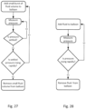
- Fig. 24 shows a graph representing a pressure balloon priming method in some embodiments.
- small volume bursts (roughly about 0.3 cc) of fluid volume are added to the pressure sensing balloon and the pressure within the balloon is measured.
- Small volume bursts of fluid are introduced until the measured pressure within the balloon settles to a stable pressure 2401. This transition is shown at inflection point 2402.
- Volume bursts are introduced past this point until the measured pressure starts to rapidly increase (for example if slope 2404 of the curve is greater than about 2mmHg/10ms).
- This inflection point is shown at 2406.
- the pressure within the balloon is reduced to a pressure around or slightly above stable pressure 2401.
- This pressure represents the prime pressure measuring pressure in some embodiments.
- This process is also represented in the flowchart in Fig. 27 .
- priming of the pressure balloon may involve pressurizing the pressure balloon well above zero mm Hg, then removing small volumes of air/gas/fluid and monitoring the pressure balloon pressure.
- the pressure balloon pressure will stabilize, or plateau, as it approaches optimal primed pressure.
- pressure measurements are taken as small volumes of air are removed from the pressure balloon, when subsequent pressure measurements are essentially the same (within about 2 mm Hg of each other), the balloon is at optimal primed pressure. If 2 subsequent measurements are not essentially equivalent, the pressure balloon is re-pressurized well above zero mm Hg and the process is repeated.
- the pressure measurements taken as small volumes of air are removed from the pressure balloon may be taken over about 5 to about 15 seconds to compensate for the effect of respiration on the pressure measurements.
- the pressure signal may require a short stabilization period after the small volume of air/gas/fluid is removed from the pressure balloon before the pressure measurement is taken.
- the small volume bursts of fluid may be from around 0.2cc to around 0.4cc.
- the small volume bursts of fluid may be from around 0.1cc to around 0.5cc.
- the small volume bursts of fluid may be up to around 0.5cc.
- the small volume bursts of fluid may be up to around 1.0cc.
- Fig. 25 shows a graph representing a pressure balloon priming method in some embodiments. This method is similar to that shown in Fig. 24 , except that the pressure is increased within the pressure sensing balloon more smoothly, without the bursts shown in Fig. 24 . Fluid volume is added to the pressure sensing balloon and the pressure within the balloon is measured. Balloon pressure is increased until the measured pressure within the balloon settles to stable pressure 2505. This transition is shown at inflection point 2506. Balloon pressure is increased past this point until the measured pressure starts to rapidly increase (for example if slope 2510 of the curve is greater than about 2mmHg/10ms). This inflection point is shown at 2508. At this point the pressure within the balloon is reduced to a pressure around or slightly above stable pressure 2505. This pressure represents the optimal, or prime, pressure in some embodiments. This process is also represented in the flowchart in Fig. 28 .
- Fig. 26 shows a flowchart of the balloon priming process of certain embodiments of the invention.
- Embodiments of the disclosed system and method include automatic pressure tuning by a controller. Accordingly, the tuning system can detect the optimum target pressure and volume to inflate the balloon by monitoring sensed pressure signals and adding or removing air volume as needed. For example, upon insertion of the catheter, a pressure tuning circuit that regulates the balloon volume and pressure will inflate the balloon until it detects a physiologic-sourced pressure rate. Upon sensing that rate, the pressure tuning controller will add or subtract minute amounts of air or fluid (roughly about 0.3 cc) in a routinized sequence until the amplitude of the sensed wave is greatest.
- the control feedback loop between the optimally tuned pressure (manifesting as balloon pressure and volume) and the sensed physiologic pressure profile iterates continuously and or as needed to ensure high fidelity measurement of the physiologic data.
- automatic pressure tuning may be performed in the apparent background while the physiologic data is being transmitted and displayed; in other embodiments the system may suspend transmission of physiologic data during a pressure tuning sequence.
- the minute amounts of air or fluid may be from around 0.2cc to around 0.4cc.
- the minute amounts of air or fluid may be from around 0.1cc to around 0.5cc.
- the minute amounts of air or fluid may be up to around 0.5cc.
- the minute amounts of air or fluid may be up to around 1.0 cc.
- priming of the balloon may be based on characteristics of the system.
- the pressure balloon may be inflated 1, 2 or more times to characterize the system, including the ultrasound transducer, the pressure pump, resistance in the system, the pressure balloon, etc.
- the pressure balloon may be pressurized over a range of pressures to determine the characteristics of the particular system at that point in time. This information is then used to optimize the inflation pressure of the pressure balloon.
- Certain patient parameters measured by the sensing Foley catheter system, and by other means, are impacted by, and/or impact, a patient's treatment through medical treatment devices.
- the loop controller can be integrated with the controller of the sensing Foley catheter system (either in the same device or in separate devices) to interpret the patient parameters to control medical treatment of the patient.
- IAP may be used to control IV infusion rate. If IAP becomes too high, infusion rate may be reduced or stopped until the IAP returns to an acceptable range.
- IAP in combination with relative stroke volume and/or stroke volume variability may allow for superior control of IV fluid or blood product infusion using IAP as indicator of excess fluid and relative stroke volume increase and reduction in stroke volume variability as indicators that additional fluid is required.
- Urine output may be further added to the control loop providing an indicator that fluid status has been restored with return of urine output.
- Heart rate in combination with respiratory rate may be used to control drug infusion (drug type, infusion rate, frequency, dosage etc.).
- IAP and respiratory rate may also be used to control a mechanical ventilator or respirator.
- PEEP positive end-expiratory pressure
- An indicator that the ventilation is not adequate can be seen in the tissue oxygenation and/or the natural respiratory rate which may be seen as a signal underlying the mechanical ventilation. This signal may either be extracted during mechanical ventilation or, preferably, the loop controller may pause the mechanical ventilator to allow more precise and accurate detection of the underlying respiratory rate/respiratory drive.
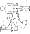
- Sensing Foley catheter 2902 includes a retention balloon inflation lumen, a pressure balloon sensing lumen, and a urine lumen.
- Pressure sensing balloon 2910 is connected to the pressure sensing lumen which is connected to pressure transducer 2920 which may be incorporated into controller 2928.
- the urine lumen is connected to urine output tube 2912.
- the urine output tube empties into urine reservoir 2914 which may be connected to urine volume measurement device 2916 or may be incorporated into the controller as disclosed herein.
- urine output may be controlled by urine pump 2918, which may be located on the urine drainage tubing, or may be incorporated into the controller, or may be located on the non-patient side of the controller as disclosed elsewhere herein.
- Balloon catheters especially balloon catheters that are designed to reside in a human or animal body for relatively long periods of time, may leak over time.
- a balloon inflated with air or another gas may leak air out of the balloon over time.
- a balloon filled with a liquid may leak liquid out over time.
- a balloon filled with gas or air which resides in fluid, such as urine, blood etc. may experience leakage of the fluid into the balloon over time. This is particularly true if the balloon is inflated at a relatively low pressure.
- Pulmonary Blood Volume Variability may also be determined by the sensing Foley catheter system to aid in assessing existence or risk of heart failure. Reduced left ventricular function can lead to an increase in the pulmonary blood volume (PBV) or a decrease in the pulmonary blood volume variation.
- PBV variation is defined as the change in PBV over time during the cardiac cycle.
- PBV can be determined as a product of the cardiac output and the pulmonary transit time (PTT).
- Cardiac output can be determined as the product of stroke volume and heart rate where stroke volume is the area under the flow-time curve for one cardiac cycle.
- Pulse transit time may be obtained by looking at the delay between the QRS complex in an EKG vs. the appearance of the signal in the bladder.
- Some embodiments of the sensing Foley catheter system include using UV light, or light of an appropriate wavelength, to sterilize the collection chamber itself or other components of the system.
- a UV light source may direct UV light through the walls of the collection chamber, or, alternatively, the UV light source may be located inside the collection chamber.
- the UV light source may be used to sterilize the collection chamber when the chamber is empty, full, or partially full.
- the UV light source may be used to sterilize the urine as it enters the collection chamber.
- the UV sterilization process may happen continually, or intermittently.
- a UV light source may be located anywhere in the sensing Foley catheter system. UV light, or other wavelength light, may be used within the bladder.
- Some embodiments of the sensing Foley catheter system include using light wavelengths in the range of around 520 nm to around 650 nm to identify bacteria, red blood cells, and/or plasma/white blood cells. See area inside oval of Fig. 61 .
- Some embodiments of the sensing Foley catheter system include combining spectrophotometry to identify white blood cells and bacteria in combination with identifying a decrease in PO2 and/or an increase in C02 to identify infection.
- Some embodiments of the sensing Foley catheter system include the controller filtering the urine output data to compensate for increased urine output immediately following the administering of a diuretic.
- Urine output generally increases immediately following the administration of a diuretic. However in certain situations it is beneficial to essentially ignore the increased urine output data associated with administration of a diuretic.
- the controller of the sensing Foley catheter system can automatically ignore the urine output data associated with the administration of a diuretic by identifying the shape of the urine output curve associated with the administration of a diuretic, and subtracting and/or ignoring the data associated with this increase. The identification of the curve shape may be done by slope, length of increase, amplitude of increase, shape, etc.
- Subtraction of diuretic induced urine output data may be beneficial in determining, or predicting, the onset of AKI. See Fig. 62 .
- the controller may identify this as a situation where a diuretic has been administered.
- Increased urine output caused by the administration of a diuretic can be differentiated from increased urine output caused by clamping, or otherwise blocking, of the urine drainage tube and/or Foley catheter.
- urine output prior to the increase will be essentially zero, or very low, for example less than 5 ml/hour.
- urine output immediately prior to the administration of the diuretic may be very low, but will likely be above zero, for example, above about 5 ml/hour.
- increased urine output following the unclamping of the drainage lumen will be for a relatively short period of time, for example, about 30 seconds to about 5 minutes.
- the controller may automatically determine when a diuretic is administered.
- the user interface of the controller may include a button or other user input device (touch screen, voice control etc.) which indicates that a diuretic has been administered. The controller will then look for an increased urine output and subtract the increased urine output attributable to the diuretic from the urine output data presented to the user.
- Some embodiments of the sensing Foley catheter system include the controller determining abdominal perfusion pressure (APP).
- APP is defined as the difference between the mean arterial pressure and the intra-abdominal pressure (IAP).
- Mean arterial pressure can be determined in conventional ways and combined with the controller's determination of IAP to determine APP.
- the controller may further automatically alter the infusion of fluids and/or pressors/vasopressors to increase or decrease blood pressure.
- Some embodiments of the sensing Foley catheter system include one or more vents and/or filters to prevent negative pressure from building within the Foley catheter and causing suction trauma to the bladder.
- a filter/vent may be located at the junction of the Foley catheter and the drainage tube or elsewhere, such as within the collection vessel or even within the lumen of the drainage tube or Foley catheter themselves, as will be described below.
- the filter/vent in some embodiments is designed to repel fluids, i.e. from hydrophobic materials. However, despite using hydrophobic materials, the filter/vent can still be susceptible to wetting by fluid, especially urine.
- Some embodiments include a larger lumen, or lumen area, where the filter/vent is located to reduce the likelihood that the surface tension of the fluid causes fluid 6302 to fill the lumen.
- Fig. 63A shows a smaller diameter lumen
- Fig. 63B shows a larger diameter lumen in the vent/filter area. Note that when vent/filter 6304 is facing upward or outward, the smaller lumen may still allow wetting of the filter/vent with fluid 6202, where a larger lumen may reduce the likelihood of wetting of the filter/vent.
- the area under or near the filter/vent may be taped to the patient's leg to stabilize the Foley catheter once it is in place.
- the larger lumen tube helps prevent wetting of the filter/vent in this situation, especially if the vent/filter is oriented away from the leg, so away from the patient.
- the vent barb may be designed so that the vent/filter is facing outward when the barb or barb area is taped to the patient's leg.
- the barb may be curved, or attached to a curved base, as shown in Fig. 64 , to better attach, and orient, to patient leg 6402.
- the barb area may be elongated, for example between 6 and 12 inches, with the vent/filter placed further from the patient, to allow the vent/filter to be placed easily in a location and manner to prevent wetting.
- vent/filters may be placed in multiple locations around the diameter of the draining lumen within the barb or elsewhere.
- a vent may encircle all, or most, of the circumference of the lumen.
- a reinforcing cuff or other structure may surround the vent to provide structural integrity to the lumen. Filter/vents may also be placed along the length of the drainage tube.
- vent tube 6502 with an inner lumen which connects to drainage lumen 6504 near barb area 6506, and is vented to atmosphere, or other air/gas/fluid via one or more filter/vents 6508 along the vent tube and/or near the other end.
- the filter/vent may be in the collection vessel as is shown in Fig. 65 , or may be elsewhere, such as separate from the collection vessel.
- a vent lumen may be incorporated into the drainage lumen, either alongside the urine drainage lumen, or within the urine drainage lumen.
- a vent lumen may alternatively be separate from the drainage lumen and connected to the drainage lumen at a vent tube/drainage tube junction, for example, near barb area 6506.
- Fig. 66 shows the sensing Foley catheter system with a positive pressure vent tube 6602 which has an inner lumen which is in fluid communication with urine drainage lumen 6604 and pump 6606.
- the positive pressure vent tube may include filter 6612 anywhere along its length, in-line or otherwise.
- the positive pressure vent tube may include a vent at either end of the tube, anywhere along the tube, or may include multiple vents.
- the pump pulls a negative pressure on the urine drainage lumen and instead of pumping the positive pressure into the atmosphere, the positive pressure is pumped back into the urine drainage lumen via the positive pressure tube.
- different pumps may be used for the negative and positive pressures.
- an exact negative or positive pressure can be controlled at the junction 6608 of the urine drainage lumen and the positive pressure vent tube.
- the pressure in junction 6608 is either slightly negative or neutral to prevent fluid flow from going back into the Foley catheter.
- the pressure in the junction may be maintained at about 0 mm Hg.
- the pressure in the junction may be maintained at about -2 mm Hg.
- Optional regulator 6610 may control the negative pressure with respect to the positive pressure, by magnitude, timing, etc.
- the regulator (which is controlled by the controller) may implement a slight delay so that negative pressure is pulled on the urine drainage line first, then at a set time later, or when a particular negative pressure is achieved, positive pressure is applied to the positive pressure tube and ultimate the positive pressure tube/drainage tube junction. This will prevent the net pressure at the positive pressure tube/drainage tube junction from being positive and causing urine to flow into the bladder rather than out of the bladder.
- the optional regulator may be in the form of a vent, of particular dimension (lower surface area or denser filter material for more resistance, larger surface area or looser filter material for less resistance).
- the positive pressure vent tube may connect to the urine drainage lumen via a valve, such as an umbrella valve with a set crack pressure.
- the positive pressure tube may be pressurized by compressed sterile fluid/gas/air.
- precise control of the negative pressure exerted on the bladder may allow for duplication of the normal filling and draining of the bladder.
- a neutral, or zero, pressure may be maintained, or even a slightly positive pressure may be maintained at the base of the Foley for a period of time so that the bladder fills normally.
- the pressure is reduced allowing for the bladder to empty, or drain.
- This process can be controlled by the controller which controls the pressure regulator to repeat this process to emulate normal filling and emptying of the bladder.
- a valve may be used at the base of the Foley catheter to better control the pressure in that area, including pressure (negative or positive) exerted on the bladder.
- positive pressure tube embodiments may be used with any of the sensing Foley catheter system embodiments, including those with different filter/vent configurations than those shown herein.
- any of the anti-airlock embodiments may be used with a regular, i.e. non-sensing, Foley catheter, or other catheters or drainage tubes.
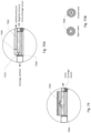
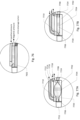
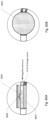
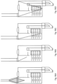
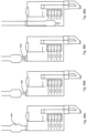
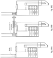
- Figs. 67-86 show magnifications of the barb area, X, of Fig. 66 to show examples of different embodiments of this area.
- valve 6702 such as an umbrella valve with a set crack pressure is shown between the lumen of positive pressure vent tube 6602 and the urine drainage lumen 6604.
- the valve may be a one-way valve.
- Vent 6704 is shown between the positive pressure vent tube and the atmosphere. Configurations may also exist where only the vent, or only the valve are present.
- Opening 6706 is in fluid communication with urine drainage lumen 6604 and chamber 6714 (with valve 6702 periodically cutting off fluid communication to the chamber).
- Chamber 6714 is in fluid communication with the lumen of positive pressure vent tube 6602. Periodically, or continuously, positive pressure is applied through positive pressure lumen 6602 and/or negative pressure is applied to urine drainage lumen 6604.
- valve 6702 When the crack pressure of valve 6702 is exceeded, fluid, preferably gas, flows through valve 6702 and through opening 6706 and through the lumen of urine drainage lumen 6604. This serves both to clear the line of airlocks or any blockages, and to clear chamber 6714 of any fluid, which reduces the likelihood of vent 6704 becoming wetted. It also serves to clear vent 6704 if it has been wetted.
- the crack pressure of valve 6702 refers to the pressure differential between positive pressure lumen 6602 and urine drainage lumen 6604. If the pressure in the urine drainage lumen is below the pressure in the positive pressure lumen by the crack pressure, the valve opens allowing fluid to flow from the positive pressure lumen, through the chamber, through opening 6706 and through the drainage lumen.
- the crack pressure may be less than about 1 mm Hg.
- the crack pressure may be less than about 2 mm Hg.
- the crack pressure may be less than about 3 mm Hg.
- the crack pressure may be less than about 4 mm Hg.
- the crack pressure may be less than about 5 mm Hg.
- the crack pressure may be less than about 10 mm Hg.
- the positive pressure in the positive pressure lumen may periodically or continually be about 5 mm Hg. Alternatively, the positive pressure in the positive pressure lumen may periodically or continually be about 7 mm Hg. Alternatively, the positive pressure in the positive pressure lumen may periodically or continually be about 10 mm Hg. Alternatively, the positive pressure in the positive pressure lumen may periodically or continually be about 15 mm Hg. Alternatively, the positive pressure in the positive pressure lumen may periodically or continually be about 20 mm Hg. Alternatively, the positive pressure in the positive pressure lumen may periodically or continually be about 25 mm Hg. Alternatively, the positive pressure in the positive pressure lumen may periodically or continually be about 30 mm Hg.
- a vent may also, or alternatively, be present elsewhere along the positive pressure vent tube, for example, close to the pump, or as part of a pressure regulator.
- a second vent/valve assembly 6708 is shown on the barb in Fig. 67 , however this second vent/valve assembly may or may not be present.
- Optional thermistor 6710 and optional pressure lumen 6712 are also shown.
- the positive pressure vent tube may alternatively be exposed to atmospheric pressure.
- the valve, or an additional valve may be present anywhere in the system, including within positive pressure tube 6602 or within the reservoir.
- Fig. 68 shows an embodiment of the barb area which includes vent 6802, valve 6804 and a small cross sectional area 6806 which is large enough to allow air/gas to flow freely from the vent to the urine drainage lumen, but small enough to prevent liquid flow to the vent.
- narrowed portion 6806 may be less than about 1mm in diameter.
- the narrowed portion may be less than about 2mm in diameter.
- the narrowed portion may be less than about 3mm in diameter.
- the narrowed portion may be less than about 4mm in diameter.
- the narrowed portion may be about 1-5mm in length.
- the narrowed portion may be about 5mm-30mm in length.
- 68 may or may not include a positive pressure tube - it is shown without a positive pressure tube (i.e. exposed to atmosphere).
- This embodiment may or may not include the valve.
- This and any embodiment may be incorporated into the barb, or may be a separate component which can be added to the barb (via a sampling or other port) or elsewhere in the system (for example along the drainage tube, preferably the 1/3 of the drainage tube closest to the patient).
- Fig. 69 shows an embodiment of the barb area which includes vent 6902 and a long vent tube 6904 which allows air/gas to flow freely from the vent to the urine drainage lumen, but is long enough to prevent liquid flow to the vent.
- vent tube portion 6904 may be about 1-10mm in diameter and may be about 1-10cm in length.
- the vent tube portion 6904 may be over about 2cm in length.
- the vent tube portion 6904 may be over about 4cm in length.
- the vent tube portion 6904 may be over about 10cm in length.
- the embodiment shown in Fig. 69 may or may not include a positive pressure tube - it is shown without a positive pressure tube. This embodiment may or may not include a valve.
- pulse oximetry data may be collected from the skin of the patient, for example, from the thigh, or elsewhere in the groin or leg area.
- the controller manages air volume and/or pressure throughout the system. For example, the controller may sense when the urine collection bag is over pressurized, which may occur if the air filter (shown as 1142 in several figures) is blocked or wet. This increases the risk that the bag may break. If this occurs, the controller may instruct the system to do one or more than one things to alleviate the problem. The controller may attempt to clear the filter by blowing "puffs" of air across the filter. The controller may slow or stop urine drainage by slowing or stopping the airlock clearance pump. The controller may instruct the pump to intermittently reverse its direction, reducing the pressure in the drainage bag. The controller may alert a user to change or otherwise manually fix the drainage bag issue.
- the air filter shown as 1142 in several figures
- acute kidney injury can be detected early or possibly predicted and/or prevented.
- AKI is classified using the RIFLE (Risk, Injury, Failure, Loss of kidney function, and End-stage kidney disease) criteria.
- the RIFLE criteria includes the following classifications: Class Urine Output Risk ⁇ 0.5 mL/kg/h ⁇ 6 h Injury ⁇ 0.5 mL/kg/h ⁇ 12 h Failure ⁇ 0.3 mL/kg/h ⁇ 24 h or anuria ⁇ 12 h
- the sensing Foley catheter system can use different algorithms, or improve upon existing algorithms to predict or identify patient conditions. For example, by factoring in earlier available urine output data, the system may be able to predict the risk of kidney injury or failure earlier than the RIFLE criteria.
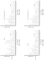
- Fig. 116A shows a graph of urine output over time, in one hour increments. Shown on the urine output scale, is a line representing 0.5 mL/kg/h. Per the RIFLE criteria, there is a risk of kidney injury if urine output is below this amount for 6 continuous hours. The last 6 urine output readings (hours 12-17) represent a condition which would be labeled as an increased risk of kidney injury per the RIFLE criteria. The sensing Foley catheter system is able to look beyond these data, and add more information to the patient's condition. For example, looking at the urine output during hours 9, 10, and 11, one can see that the urine output was declining each of these hours.
- the sensing Foley system may predict AKI Risk up to 1 hour earlier than the RIFLE criteria. Alternatively, the sensing Foley system may predict AKI Risk up to 2 hours earlier than the RIFLE criteria. Alternatively, the sensing Foley system may predict AKI Risk up to 3 hours earlier than the RIFLE criteria. Alternatively, the sensing Foley system may predict AKI Risk up to 4 hours earlier than the RIFLE criteria. Alternatively, the sensing Foley system may predict AKI Risk up to 5 hours earlier than the RIFLE criteria. Alternatively, the sensing Foley system may predict AKI Risk up to 6 hours earlier than the RIFLE criteria.
- the sensing Foley system may predict AKI Risk more than 1 hour earlier than the RIFLE criteria.
- the sensing Foley system may predict AKI Risk more than 2 hours earlier than the RIFLE criteria.
- the sensing Foley system may predict AKI Risk more than 3 hours earlier than the RIFLE criteria.
- the sensing Foley system may predict AKI Risk more than 4 hours earlier than the RIFLE criteria.
- the sensing Foley system may predict AKI Risk more than 5 hours earlier than the RIFLE criteria.
- the sensing Foley system may predict AKI Risk more than 6 hours earlier than the RIFLE criteria.
- the sensing Foley system may predict Kidney Injury up to 1 hour earlier than the RIFLE criteria. Alternatively, the sensing Foley system may predict Kidney Injury up to 2 hours earlier than the RIFLE criteria. Alternatively, the sensing Foley system may predict Kidney Injury up to 3 hours earlier than the RIFLE criteria. Alternatively, the sensing Foley system may predict Kidney Injury up to 4 hours earlier than the RIFLE criteria. Alternatively, the sensing Foley system may predict Kidney Injury up to 5 hours earlier than the RIFLE criteria. Alternatively, the sensing Foley system may predict Kidney Injury up to 6 hours earlier than the RIFLE criteria.
- the sensing Foley system may predict Kidney Injury more than 1 hour earlier than the RIFLE criteria.
- the sensing Foley system may predict Kidney Injury more than 2 hours earlier than the RIFLE criteria.
- the sensing Foley system may predict Kidney Injury more than 3 hours earlier than the RIFLE criteria.
- the sensing Foley system may predict Kidney Injury more than 4 hours earlier than the RIFLE criteria.
- the sensing Foley system may predict Kidney Injury more than 5 hours earlier than the RIFLE criteria.
- the sensing Foley system may predict Kidney Injury more than 6 hours earlier than the RIFLE criteria.
- the sensing Foley system may predict Kidney Failure up to 1 hour earlier than the RIFLE criteria. Alternatively, the sensing Foley system may predict Kidney Failure up to 2 hours earlier than the RIFLE criteria. Alternatively, the sensing Foley system may predict Kidney Failure up to 3 hours earlier than the RIFLE criteria. Alternatively, the sensing Foley system may predict Kidney Failure up to 4 hours earlier than the RIFLE criteria. Alternatively, the sensing Foley system may predict Kidney Failure up to 5 hours earlier than the RIFLE criteria. Alternatively, the sensing Foley system may predict Kidney Failure up to 6 hours earlier than the RIFLE criteria.
- the sensing Foley system may predict Kidney Failure more than 1 hour earlier than the RIFLE criteria.
- the sensing Foley system may predict Kidney Failure more than 2 hours earlier than the RIFLE criteria.
- the sensing Foley system may predict Kidney Failure more than 3 hours earlier than the RIFLE criteria.
- the sensing Foley system may predict Kidney Failure more than 4 hours earlier than the RIFLE criteria.
- the sensing Foley system may predict Kidney Failure more than 5 hours earlier than the RIFLE criteria.
- the sensing Foley system may predict Kidney Failure more than 6 hours earlier than the RIFLE criteria.
- RIFLE Risk may be identified 3 hours earlier than predicted by the traditional RIFLE criteria. In some embodiments of the sensing Foley system, RIFLE Risk may be identified 1-3 hours earlier than predicted by the traditional RIFLE criteria. RIFLE Risk may be identified 1-2 hours earlier than predicted by the traditional RIFLE criteria. RIFLE Risk may be identified 3-5 hours earlier than predicted by the traditional RIFLE criteria.
- the pump may have 2 rollers, or may have 1 roller, or more than 2 rollers.
- the channels may be configured in any arrangement that allows the proper function of the pump.
- the pump may operate continuously, or intermittently.
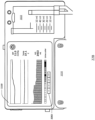
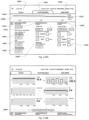
- Figs. 118A - 118C show example screenshots for embodiments disclosed herein. These screenshots may be displayed on the monitor/controller or may be displayed remotely, for example on a computer or tablet. These screenshots may be particularly applicable to embodiments which include a controlled feedback loop, or loop controller, such as the embodiments shown in Figs. 29-33 .
- urine output area 11814 displays the option to connect or disconnect this device to the loop control system. Connecting this device may be performed via this screen when any embodiment of the sensing Foley catheter of the sensing Foley catheter system is inserted into the patient. Shown here also is the date the sensing Foley catheter was inserted and how many days it has been indwelling. The urine output rate and/or volume may be used in the fluid balance analysis by the loop controller.
- IV infusion pump area 11824 may show whether, and what model, infusion pump is connected to the loop controller. Other settings may include infusion volume and infusion rate. The infusion rate and/or volume may be used in the fluid balance analysis by the loop controller.
- Wound drainage area 11822 may show whether, and what model, wound drainage system is connected to the loop controller.
- the wound drainage rate and/or volume may be used in the fluid balance analysis by the loop controller.
- pulse oxymeter area 11818 and ECG area 11820 are also shown here. Although these are not directly related to fluid balance, they may also be monitored by the loop controller. These sensors may be part of the sensing Foley system for example.
- the loop controller can maintain the desired fluid balance within the patient. For example, if the patient is urinating at a volume rate which is higher than the input fluid rate from feeding and/or infusion, then the fluid balance of the patient is going more negative. If the fluid balance drops below the desired range, the feeding rate and/or the infusion rate may be increased to bring the fluid balance back to within the desired range. Or, if the fluid balance is going too positive (too much fluid in the body), the feeding rate and/or infusion rate may be decrease until the fluid balance is brought back within the desired range. Other fluid output measures may also be included where appropriate, such as wound drainage, shown in area 11822.
- Fluid loss from sweat, exhalation, and fecal output may also be taken into consideration by the loop controller in the fluid balance analysis. These devices connections are not shown here on this screen, but may be included.
- the desired fluid balance range may be set via the settings, for example area 11825 shown here.
- the various connected devices may be automatically sensed via Bluetooth or other mechanisms or connected manually.
- Fig. 118B shows another example screen of the loop controller system.
- This screen shows an example of what may be shown within the "vitals" tab area.
- This area shows one or more vital sign of the patient over time.
- the time frame may be changed, for example, via buttons 11826. Shown here are the patient temperature, the heart rate, the respiration rate, the urine output (or alternatively urine output rate), the intraabdominal pressure, and the pulse oximeter readings over time.
- Other vital signs may be shown as well. For example, ECG, weight, blood pressure, etc. Some or all of these measurements may be collected by the sensing Foley catheter system.
- Fig. 118C shows an example of a screen behind the "fluid balance" tab.
- the settings area shown in Fig. 118A has been minimized to the bottom of the screen.
- the ongoing and current actual fluid balance and desired fluid balance are shown at the top of the screen.
- the IV infusion, enteral feeding, urine output, and wound drainage volumes over time where applicable.
- a wound drainage device is not being used on the patient so that graph does not shown data.
- the risk area of the display may show risk of various medical conditions based on some or all of the data collected from the sensing Foley catheter system and/or other devices. For example, AKI risk, sepsis risk, and other risk may be assessed by the controller and displayed here. Settings for various parameters used in the assessment of risk may also be entered into or gathered by the controller. For example, patient weight may be entered into the risk profile.
- Fig. 119A-B show an embodiment of the sensing Foley catheter system which includes the analysis and recording of various urine parameters.
- Fig. 119A shows a cassette for collecting the urine output, which includes optically clear section 11904 and test strip 11906.
- Test strip 11906 includes one or more test strip segments 11908.
- the test strip segments may change color based on various parameters of the urine. For example, test strip segments may test for the presence of leukocytes, nitrite, urobilinogen, protein, hemoglobin ketone, bilirubin, acetone, glucose, hormones, drugs, creatinine or other entities, or the test strip may determine the pH, specific gravity, color, or other parameters of the urine.
- the test strip segments may also test for pathogens
- Camera 11902 which preferably is a visible light camera but may be a camera which senses wavelengths of light outside the visible spectrum, may be incorporated into the monitor/controller.
- the camera may be move up and down, either automatically by the controller, or manually, to capture images of the various rows of test strip segments on the test strip.
- the camera lens may have a wide enough angle to capture an area large enough to monitor the fluid level over the necessary range.
- multiple cameras may be included and be in communication with the controller.
- Test strip 11906 may include multiple rows of multiple test strip segments. Preferably, each row is identical, but they may be different. Each row may contain one or more test strip segments, each of which may test a different parameter.
- the test strip might include more than one row of 2 different test strip segments.
- the test strip might include more than one row of 3 different test strip segments.
- the test strip might include more than one row of 4 different test strip segments.
- the test strip might include more than one row of 5 different test strip segments.
- the test strip might include more than one row of 6 different test strip segments.
- the test strip might include more than one row of 7 different test strip segments.
- the test strip might include more than one row of 8 different test strip segments.
- the test strip might include more than one row of 9 different test strip segments.
- the test strip might include more than one row of 10 different test strip segments.
- the test strip might include more than one row of more than 1 different test strip segments.
- the test strip might include more than one row of more than 2 different test strip segments.
- the test strip might include more than one row of more than 3 different test strip segments.
- the test strip might include more than one row of more than 5 different test strip segments.
- Fig. 119B shows test strip 11906 with 10 rows of 7 different test strip segments.
- the test strip array may be enclosed within the urine collection chamber, as shown in Fig. 119A .
- Urine may come in contact with first the bottom row of test strip segments as the urine is collected in the chamber.
- the bottom (first) row of test strip segments may be above the level corresponding to the emptying volume of the collection chamber.
- urine may be brought into contact with, first the lower row of test strip segments, by the controller controlling the pump to pull a vacuum via cassette pump interface 1148. The vacuum pulled by the vacuum pump will temporarily lift the column of urine in cylinder 11909 of the cassette, via vacuum path 11910, allowing the urine to contact subsequent rows of test strip segments.
- the controller may be programmed to pull a vacuum periodically to expose the subsequently higher row of test strip segments to urine periodically, to test the urine as it is collected. In this way, fresh test strip can be exposed to urine so that several separate tests may be run.
- the number of rows of the test strip corresponds to the number of fresh tests which can be run with each test strip. For example, test strip row 1 will be used first, then row 2, etc.
- the camera may move incrementally higher as each row of the test strip is used. Alternatively, the camera may change its viewing angle to view subsequent rows of the test strip.
- test strip may be replaced via a sterile cartridge, which may be removed, and replaced.
- the camera can detect the color of the row of test strip segments and compare it to a standard color array to determine whether any of the test strip segment parameter show that the urine is out of range for that parameter.
- the camera may be calibrated to the standard color array.
- test strip readings may be performed manually, rather than automatically via a camera/controller.
- a pressure sensor may be included elsewhere in the system, for example at the barb area, to monitor the pressure within the system (positive or negative pressure) to determine when the pressure is optimal for fluid drainage.
- a signal from a pressure sensor at the barb may be monitored by the monitor/controller so that it is an optimal pressure range, for example, around 0.5 mm Hg.
- This optimal pressure range may allow for proper airlock clearance and fluid drainage, without exerting excessive negative pressure on the bladder.
- the controlling of this optimal pressure range may be done periodically, or continuously, by controller the pump which is creating the negative pressure within the drainage tube. If run continuously, the speed of the pump may be controlled by the monitor/controller to maintain the proper pressure range within the system.
- a flow meter or flow sensor may be incorporated into the system.
- a flow meter may be added to the vent tube to monitor air flow to better control the airlock clearance function. The flow is sensed by the flow meter and the signal communicated to the controller.
- a flow sensor or meter may exist elsewhere in the system.
- an overflow barrier or an overflow path may be incorporated into the reservoir/cassette.
- sensing Foley system may incorporate comprehensive "smart” sensing, including any sensing types disclosed herein.
- a “smart" Foley catheter sensing system may include:
Landscapes
- Health & Medical Sciences (AREA)
- Life Sciences & Earth Sciences (AREA)
- Heart & Thoracic Surgery (AREA)
- General Health & Medical Sciences (AREA)
- Animal Behavior & Ethology (AREA)
- Engineering & Computer Science (AREA)
- Biomedical Technology (AREA)
- Veterinary Medicine (AREA)
- Public Health (AREA)
- Molecular Biology (AREA)
- Pathology (AREA)
- Physics & Mathematics (AREA)
- Medical Informatics (AREA)
- Biophysics (AREA)
- Surgery (AREA)
- Physiology (AREA)
- Cardiology (AREA)
- Hematology (AREA)
- Pulmonology (AREA)
- Urology & Nephrology (AREA)
- Vascular Medicine (AREA)
- Anesthesiology (AREA)
- External Artificial Organs (AREA)
- Measurement Of The Respiration, Hearing Ability, Form, And Blood Characteristics Of Living Organisms (AREA)
- Measuring And Recording Apparatus For Diagnosis (AREA)
- Investigating Or Analysing Biological Materials (AREA)
Claims (11)
- System zur Beurteilung der Gesundheit eines Patienten,
wobei das System ein Foley-Kathetersystem mit Sensor ist, welches derart konfiguriert ist, dass es Urinaustritt misst, wobei das System ferner aufweist:einen Ablaufschlauch (1001; 1012), welcher derart konfiguriert ist, dass er in Fluidverbindung mit zumindest einer Öffnung steht, die in der Nähe oder an einem distalen Ende eines Katheters (102; 1000) positioniert ist;eine Pumpe (2918; 3106; 6606), die in Fluidverbindung mit dem Ablaufschlauch (1001; 1012) steht und derart konfiguriert ist, dass sie einen Unterdruck an den Ablaufschlauch (1001; 1012) anlegt;ein Ventil, das für eine unidirektionale Strömung konfiguriert ist und in Fluidverbindung mit dem Ablaufschlauch (1001; 1012) steht; undeine Steuervorrichtung in Verbindung mit der Pumpe (2918; 3106; 6606), wobei die Steuervorrichtung derart konfiguriert ist, dass sie die Pumpe (2918; 3106; 6606) betätigt, um den Unterdruck anzulegen, um eine Luftschleuse aus dem Ablaufschlauch (1001; 1012) zu entfernen,wobei die Steuervorrichtung konfiguriert ist, um einen Urinaustritt aus dem Patienten über eine erste Zeitspanne oberhalb eines Urinaustrittsschwellenwerts von 0,5 mL/kg/Stunde und über eine zweite Zeitspanne unterhalb eines Urinaustrittsschwellenwerts zu überwachen, undwobei die Steuervorrichtung ferner derart konfiguriert ist, dass sie ein Risiko für eine akute Nierenschädigung bestimmt, wenn ein mehrstündiger Trend sinkenden Urinaustritts 3 Stunden Urinausaustritt unterhalb des Urinaustrittsschwellenwerts von 0,5 mL/kg/Stunde vorausgeht. - System nach Anspruch 1, wobei die Pumpe (2918; 3106; 6606) derart konfiguriert ist, dass sie periodisch betätigt wird.
- System nach Anspruch 1, ferner aufweisend einen Sammelbehälter (1022) in Fluidverbindung mit dem Ablaufschlauch (1001; 1012), um den Urinaustritt des Patienten aufzunehmen.
- System nach Anspruch 3, wobei die Steuervorrichtung derart konfiguriert ist, dass sie den Urinaustritt innerhalb des Sammelbehälters (1022) bestimmt.
- System nach Anspruch 3, wobei der Sammelbehälter (1022) derart konfiguriert ist, dass er sich entleert, nachdem ein vorbestimmtes Volumen innerhalb des Sammelbehälters (1022) erreicht wurde.
- System nach Anspruch 1, wobei der Urinaustritt zumindest in stündlichen Inkrementen gesammelt wird.
- System nach Anspruch 1, wobei die erste vorbestimmte Zeitspanne zumindest 3 Stunden beträgt.
- System nach Anspruch 1, wobei die Steuervorrichtung ferner derart konfiguriert ist, dass sie die Pumpe (2918; 3106; 6606) betätigt, um den Unterdruck auf einer ersten Ebene zum Entfernen einer Luftschleuse aus dem Ablaufschlauch (1001; 1012), und danach auf einer zweiten Ebene anzulegen.
- System nach Anspruch 8, wobei der Unterdruck auf der zweiten Ebene angelegt wird, unmittelbar nachdem die Luftschleuse aus dem Ablaufschlauch (1001; 1012) entfernt wurde.
- System nach Anspruch 9, wobei der Unterdruck für eine vorbestimmte Zeitspanne auf der zweiten Ebene angelegt wird, nachdem die Luftschleuse aus dem Ablaufschlauch (1001; 1012) entfernt wurde.
- System nach Anspruch 1, wobei die Steuervorrichtung ferner derart konfiguriert ist, dass sie das Risiko einer akuten Nierenschädigung auf Grundlage des Urinaustritts und eines der folgenden Faktoren bestimmt:Gewicht des Patienten; oderAtemfrequenz des Patienten; oderHerzfrequenz des Patienten.
Priority Applications (1)
| Application Number | Priority Date | Filing Date | Title |
|---|---|---|---|
| EP25178481.5A EP4603006A3 (de) | 2018-04-02 | 2019-03-26 | Systeme, vorrichtungen und verfahren zur drainage und analyse von körperflüssigkeiten und beurteilung der gesundheit |
Applications Claiming Priority (5)
| Application Number | Priority Date | Filing Date | Title |
|---|---|---|---|
| US201862651377P | 2018-04-02 | 2018-04-02 | |
| US201862756473P | 2018-11-06 | 2018-11-06 | |
| US201862776388P | 2018-12-06 | 2018-12-06 | |
| US201962798365P | 2019-01-29 | 2019-01-29 | |
| PCT/US2019/024050 WO2019195028A1 (en) | 2018-04-02 | 2019-03-26 | Systems, devices and methods for draining and analyzing bodily fluids and assessing health |
Related Child Applications (2)
| Application Number | Title | Priority Date | Filing Date |
|---|---|---|---|
| EP25178481.5A Division EP4603006A3 (de) | 2018-04-02 | 2019-03-26 | Systeme, vorrichtungen und verfahren zur drainage und analyse von körperflüssigkeiten und beurteilung der gesundheit |
| EP25178481.5A Division-Into EP4603006A3 (de) | 2018-04-02 | 2019-03-26 | Systeme, vorrichtungen und verfahren zur drainage und analyse von körperflüssigkeiten und beurteilung der gesundheit |
Publications (4)
| Publication Number | Publication Date |
|---|---|
| EP3761876A1 EP3761876A1 (de) | 2021-01-13 |
| EP3761876A4 EP3761876A4 (de) | 2021-12-22 |
| EP3761876C0 EP3761876C0 (de) | 2025-07-02 |
| EP3761876B1 true EP3761876B1 (de) | 2025-07-02 |
Family
ID=68101196
Family Applications (2)
| Application Number | Title | Priority Date | Filing Date |
|---|---|---|---|
| EP19781319.9A Active EP3761876B1 (de) | 2018-04-02 | 2019-03-26 | System zur drainage und analyse von körperflüssigkeiten und zur beurteilung der gesundheit |
| EP25178481.5A Pending EP4603006A3 (de) | 2018-04-02 | 2019-03-26 | Systeme, vorrichtungen und verfahren zur drainage und analyse von körperflüssigkeiten und beurteilung der gesundheit |
Family Applications After (1)
| Application Number | Title | Priority Date | Filing Date |
|---|---|---|---|
| EP25178481.5A Pending EP4603006A3 (de) | 2018-04-02 | 2019-03-26 | Systeme, vorrichtungen und verfahren zur drainage und analyse von körperflüssigkeiten und beurteilung der gesundheit |
Country Status (7)
| Country | Link |
|---|---|
| US (1) | US20250017504A1 (de) |
| EP (2) | EP3761876B1 (de) |
| JP (3) | JP7221985B2 (de) |
| CN (2) | CN119454032A (de) |
| AU (2) | AU2019249070B2 (de) |
| CA (1) | CA3094993A1 (de) |
| WO (1) | WO2019195028A1 (de) |
Families Citing this family (24)
| Publication number | Priority date | Publication date | Assignee | Title |
|---|---|---|---|---|
| US12114978B2 (en) | 2018-04-02 | 2024-10-15 | Potrero Medical, Inc. | Systems, devices and methods for draining and analyzing bodily fluids and assessing health |
| GB2576043B (en) * | 2018-08-03 | 2023-04-19 | Medisyne Ltd | Healthcare monitoring system |
| JP7312262B2 (ja) | 2018-09-28 | 2023-07-20 | フロー メディカル コーポレイション | カテーテル装置 |
| US20210074396A1 (en) * | 2019-09-09 | 2021-03-11 | Medtronic, Inc. | Smart card password management systems and methods for medical systems |
| EP3808426B1 (de) * | 2019-10-18 | 2024-11-27 | Roche Diagnostics GmbH | Techniken zur überprüfung des zustands von analysatoren |
| US12415057B2 (en) * | 2019-10-31 | 2025-09-16 | Musc Foundation For Research Development | Ultrasound-based shunt flow detection |
| WO2021126698A1 (en) * | 2019-12-18 | 2021-06-24 | Potrero Medical, Inc. | Systems, devices and methods for draining and analyzing bodily fluids and assessing health |
| CA3168246A1 (en) * | 2020-01-16 | 2021-07-22 | Starling Medical, Inc. | Bodily fluid management sytem |
| US12042607B2 (en) | 2020-04-23 | 2024-07-23 | Covidien Lp | Catheter with valves |
| JP7657913B2 (ja) | 2020-08-19 | 2025-04-07 | オーグメント ヘルス インコーポレイテッド | 尿道カテーテルシステムおよび方法 |
| US20220076838A1 (en) * | 2020-09-04 | 2022-03-10 | Covidien Lp | Acute kidney injury monitoring |
| US11864893B2 (en) | 2020-09-04 | 2024-01-09 | Covidien Lp | Oxygen sensor calibration |
| US20220087904A1 (en) * | 2020-09-21 | 2022-03-24 | Luminoah, Inc. | Wearable fluid delivery system |
| TWI752675B (zh) * | 2020-10-14 | 2022-01-11 | 亞東技術學院 | 智慧型多功能尿袋裝置 |
| CN112773950A (zh) * | 2021-01-04 | 2021-05-11 | 绵阳美科电子设备有限责任公司 | 留置测压导尿装置以及应用装置的膀胱监护仪和应用方法 |
| JPWO2022209694A1 (de) * | 2021-03-31 | 2022-10-06 | ||
| KR102941793B1 (ko) * | 2022-07-18 | 2026-03-19 | 고승현 | 살균기능을 가지는 배뇨량 측정장치 |
| CN115153556B (zh) * | 2022-07-22 | 2024-12-10 | 佛山市第一人民医院(中山大学附属佛山医院) | 一种尿量计量监控系统 |
| CN115363629A (zh) * | 2022-09-02 | 2022-11-22 | 上海图瞳科技有限公司 | 膀胱尿量实时监测方法和装置 |
| CN115796082B (zh) * | 2023-01-13 | 2023-06-06 | 张家港市欧凯医疗器械有限公司 | 一种双j型导管内径引流数据分析方法及系统 |
| CN116271276A (zh) * | 2023-03-09 | 2023-06-23 | 浙江医鼎医用敷料有限公司 | 一种双模式且加速愈合的负压创伤治疗仪 |
| CN116370727B (zh) * | 2023-04-18 | 2024-07-05 | 中国人民解放军陆军军医大学第二附属医院 | 一种胸腔积液负压吸引器 |
| CN119150006B (zh) * | 2024-11-15 | 2025-01-24 | 吉林大学第一医院 | 一种用于引流管的术后引流量监测方法及系统 |
| CN119770832B (zh) * | 2024-12-31 | 2025-11-11 | 常熟伟盛医疗用品有限公司 | 一种防漏防堵导尿管及其应用方法 |
Citations (1)
| Publication number | Priority date | Publication date | Assignee | Title |
|---|---|---|---|---|
| WO2016049654A1 (en) * | 2014-09-28 | 2016-03-31 | Potrero Medical, Inc. | Systems, devices and methods for sensing physiologic data and draining and analyzing bodily fluids |
Family Cites Families (9)
| Publication number | Priority date | Publication date | Assignee | Title |
|---|---|---|---|---|
| US5409014A (en) * | 1993-08-13 | 1995-04-25 | Dravon Medical, Inc. | Fluid meter |
| US6500158B1 (en) * | 1997-03-26 | 2002-12-31 | The Trustees Of Columbia University In The City Of New York | Method of inducing negative pressure in the urinary collecting system and apparatus therefor |
| US20130218106A1 (en) * | 2010-07-30 | 2013-08-22 | C. R. Bard, Inc. | Automated Method of Pooling Elimination with a Biological Fluid Collection System |
| US20140378918A1 (en) * | 2011-12-31 | 2014-12-25 | Beijing Winsunny Harmony Science And Technology Co., Ltd. | Urine drainage device, drainage control device, drainage control system and voiding method |
| EP3092029B1 (de) * | 2014-01-07 | 2025-10-29 | Potrero Medical, Inc. | Systeme, vorrichtungen und verfahren zur drainage und analyse von körperflüssigkeiten |
| KR102431003B1 (ko) * | 2014-10-20 | 2022-08-09 | 아스튜트 메디컬 인코포레이티드 | 신손상 및 신부전의 진단 및 예후를 위한 방법 및 조성물 |
| EP3282948A4 (de) * | 2015-04-15 | 2019-04-03 | The Johns Hopkins University | System sowie urinmessvorrichtungen und verfahren zur überwachung der nierenfunktion |
| US10391275B2 (en) * | 2015-11-17 | 2019-08-27 | Potrero Medical, Inc. | Systems, devices and methods for draining and analyzing bodily fluids |
| CN109152532B (zh) | 2016-06-10 | 2021-12-14 | 泰尔茂株式会社 | 氧测定装置 |
-
2019
- 2019-03-26 CA CA3094993A patent/CA3094993A1/en active Pending
- 2019-03-26 EP EP19781319.9A patent/EP3761876B1/de active Active
- 2019-03-26 EP EP25178481.5A patent/EP4603006A3/de active Pending
- 2019-03-26 WO PCT/US2019/024050 patent/WO2019195028A1/en not_active Ceased
- 2019-03-26 JP JP2020551531A patent/JP7221985B2/ja active Active
- 2019-03-26 AU AU2019249070A patent/AU2019249070B2/en active Active
- 2019-03-26 CN CN202411611159.7A patent/CN119454032A/zh active Pending
- 2019-03-26 CN CN201980033749.7A patent/CN112165899B/zh active Active
-
2023
- 2023-02-02 JP JP2023014508A patent/JP7560583B2/ja active Active
-
2024
- 2024-08-23 US US18/814,206 patent/US20250017504A1/en active Pending
- 2024-09-05 AU AU2024219427A patent/AU2024219427A1/en active Pending
- 2024-09-19 JP JP2024161663A patent/JP7693927B2/ja active Active
Patent Citations (1)
| Publication number | Priority date | Publication date | Assignee | Title |
|---|---|---|---|---|
| WO2016049654A1 (en) * | 2014-09-28 | 2016-03-31 | Potrero Medical, Inc. | Systems, devices and methods for sensing physiologic data and draining and analyzing bodily fluids |
Also Published As
| Publication number | Publication date |
|---|---|
| JP2023055859A (ja) | 2023-04-18 |
| AU2024219427A1 (en) | 2024-10-31 |
| EP3761876C0 (de) | 2025-07-02 |
| US20250017504A1 (en) | 2025-01-16 |
| JP2021519128A (ja) | 2021-08-10 |
| JP2024178288A (ja) | 2024-12-24 |
| EP4603006A3 (de) | 2025-12-10 |
| AU2019249070A1 (en) | 2020-10-22 |
| JP7221985B2 (ja) | 2023-02-14 |
| CN112165899A (zh) | 2021-01-01 |
| CN112165899B (zh) | 2024-11-19 |
| JP7560583B2 (ja) | 2024-10-02 |
| EP4603006A2 (de) | 2025-08-20 |
| EP3761876A1 (de) | 2021-01-13 |
| WO2019195028A1 (en) | 2019-10-10 |
| CN119454032A (zh) | 2025-02-18 |
| JP7693927B2 (ja) | 2025-06-17 |
| EP3761876A4 (de) | 2021-12-22 |
| AU2019249070B2 (en) | 2024-06-13 |
| CA3094993A1 (en) | 2019-10-10 |
Similar Documents
| Publication | Publication Date | Title |
|---|---|---|
| AU2022275493B2 (en) | Systems, devices and methods for draining and analyzing bodily fluids | |
| US20250017504A1 (en) | Systems, devices and methods for draining and analyzing bodily fluids and assessing health | |
| US20220273213A1 (en) | Systems, devices and methods for draining and analyzing bodily fluids and assessing health | |
| EP3548133B1 (de) | Systeme, vorrichtungen und verfahren zur drainage und analyse von körperflüssigkeiten | |
| AU2020256358B2 (en) | Systems, devices and methods for sensing physiologic data and draining and analyzing bodily fluids | |
| US12114978B2 (en) | Systems, devices and methods for draining and analyzing bodily fluids and assessing health | |
| US20240099624A1 (en) | Systems, devices and methods for draining and analyzing bodily fluids, pressures and assessing health |
Legal Events
| Date | Code | Title | Description |
|---|---|---|---|
| STAA | Information on the status of an ep patent application or granted ep patent |
Free format text: STATUS: THE INTERNATIONAL PUBLICATION HAS BEEN MADE |
|
| PUAI | Public reference made under article 153(3) epc to a published international application that has entered the european phase |
Free format text: ORIGINAL CODE: 0009012 |
|
| STAA | Information on the status of an ep patent application or granted ep patent |
Free format text: STATUS: REQUEST FOR EXAMINATION WAS MADE |
|
| 17P | Request for examination filed |
Effective date: 20201009 |
|
| AK | Designated contracting states |
Kind code of ref document: A1 Designated state(s): AL AT BE BG CH CY CZ DE DK EE ES FI FR GB GR HR HU IE IS IT LI LT LU LV MC MK MT NL NO PL PT RO RS SE SI SK SM TR |
|
| AX | Request for extension of the european patent |
Extension state: BA ME |
|
| DAV | Request for validation of the european patent (deleted) | ||
| DAX | Request for extension of the european patent (deleted) | ||
| A4 | Supplementary search report drawn up and despatched |
Effective date: 20211124 |
|
| RIC1 | Information provided on ipc code assigned before grant |
Ipc: A61B 5/11 20060101ALN20211118BHEP Ipc: A61B 5/024 20060101ALN20211118BHEP Ipc: A61B 5/08 20060101ALN20211118BHEP Ipc: A61B 5/0205 20060101ALI20211118BHEP Ipc: A61B 5/00 20060101ALI20211118BHEP Ipc: A61B 5/20 20060101AFI20211118BHEP |
|
| STAA | Information on the status of an ep patent application or granted ep patent |
Free format text: STATUS: EXAMINATION IS IN PROGRESS |
|
| 17Q | First examination report despatched |
Effective date: 20220623 |
|
| GRAP | Despatch of communication of intention to grant a patent |
Free format text: ORIGINAL CODE: EPIDOSNIGR1 |
|
| STAA | Information on the status of an ep patent application or granted ep patent |
Free format text: STATUS: GRANT OF PATENT IS INTENDED |
|
| INTG | Intention to grant announced |
Effective date: 20250210 |
|
| RIC1 | Information provided on ipc code assigned before grant |
Ipc: A61B 5/11 20060101ALN20250203BHEP Ipc: A61B 5/024 20060101ALN20250203BHEP Ipc: A61B 5/08 20060101ALN20250203BHEP Ipc: A61B 5/0205 20060101ALI20250203BHEP Ipc: A61B 5/00 20060101ALI20250203BHEP Ipc: A61B 5/20 20060101AFI20250203BHEP |
|
| GRAS | Grant fee paid |
Free format text: ORIGINAL CODE: EPIDOSNIGR3 |
|
| GRAA | (expected) grant |
Free format text: ORIGINAL CODE: 0009210 |
|
| STAA | Information on the status of an ep patent application or granted ep patent |
Free format text: STATUS: THE PATENT HAS BEEN GRANTED |
|
| AK | Designated contracting states |
Kind code of ref document: B1 Designated state(s): AL AT BE BG CH CY CZ DE DK EE ES FI FR GB GR HR HU IE IS IT LI LT LU LV MC MK MT NL NO PL PT RO RS SE SI SK SM TR |
|
| REG | Reference to a national code |
Ref country code: GB Ref legal event code: FG4D |
|
| REG | Reference to a national code |
Ref country code: CH Ref legal event code: EP |
|
| REG | Reference to a national code |
Ref country code: DE Ref legal event code: R096 Ref document number: 602019071972 Country of ref document: DE |
|
| REG | Reference to a national code |
Ref country code: IE Ref legal event code: FG4D |
|
| U01 | Request for unitary effect filed |
Effective date: 20250708 |
|
| U07 | Unitary effect registered |
Designated state(s): AT BE BG DE DK EE FI FR IT LT LU LV MT NL PT RO SE SI Effective date: 20250718 |
|
| U1N | Appointed representative for the unitary patent procedure changed after the registration of the unitary effect |
Representative=s name: LORENZ SEIDLER GOSSEL PART. MBB; DE |
|
| PG25 | Lapsed in a contracting state [announced via postgrant information from national office to epo] |
Ref country code: IS Free format text: LAPSE BECAUSE OF FAILURE TO SUBMIT A TRANSLATION OF THE DESCRIPTION OR TO PAY THE FEE WITHIN THE PRESCRIBED TIME-LIMIT Effective date: 20251102 |
|
| PG25 | Lapsed in a contracting state [announced via postgrant information from national office to epo] |
Ref country code: NO Free format text: LAPSE BECAUSE OF FAILURE TO SUBMIT A TRANSLATION OF THE DESCRIPTION OR TO PAY THE FEE WITHIN THE PRESCRIBED TIME-LIMIT Effective date: 20251002 |
|
| PG25 | Lapsed in a contracting state [announced via postgrant information from national office to epo] |
Ref country code: HR Free format text: LAPSE BECAUSE OF FAILURE TO SUBMIT A TRANSLATION OF THE DESCRIPTION OR TO PAY THE FEE WITHIN THE PRESCRIBED TIME-LIMIT Effective date: 20250702 |
|
| PG25 | Lapsed in a contracting state [announced via postgrant information from national office to epo] |
Ref country code: GR Free format text: LAPSE BECAUSE OF FAILURE TO SUBMIT A TRANSLATION OF THE DESCRIPTION OR TO PAY THE FEE WITHIN THE PRESCRIBED TIME-LIMIT Effective date: 20251003 |
|
| PG25 | Lapsed in a contracting state [announced via postgrant information from national office to epo] |
Ref country code: CZ Free format text: LAPSE BECAUSE OF FAILURE TO SUBMIT A TRANSLATION OF THE DESCRIPTION OR TO PAY THE FEE WITHIN THE PRESCRIBED TIME-LIMIT Effective date: 20250702 |
|
| PG25 | Lapsed in a contracting state [announced via postgrant information from national office to epo] |
Ref country code: PL Free format text: LAPSE BECAUSE OF FAILURE TO SUBMIT A TRANSLATION OF THE DESCRIPTION OR TO PAY THE FEE WITHIN THE PRESCRIBED TIME-LIMIT Effective date: 20250702 |
|
| PG25 | Lapsed in a contracting state [announced via postgrant information from national office to epo] |
Ref country code: RS Free format text: LAPSE BECAUSE OF FAILURE TO SUBMIT A TRANSLATION OF THE DESCRIPTION OR TO PAY THE FEE WITHIN THE PRESCRIBED TIME-LIMIT Effective date: 20251002 |
|
| PG25 | Lapsed in a contracting state [announced via postgrant information from national office to epo] |
Ref country code: ES Free format text: LAPSE BECAUSE OF FAILURE TO SUBMIT A TRANSLATION OF THE DESCRIPTION OR TO PAY THE FEE WITHIN THE PRESCRIBED TIME-LIMIT Effective date: 20250702 |
|
| U20 | Renewal fee for the european patent with unitary effect paid |
Year of fee payment: 8 Effective date: 20260219 |
|
| REG | Reference to a national code |
Ref country code: CH Ref legal event code: U11 Free format text: ST27 STATUS EVENT CODE: U-0-0-U10-U11 (AS PROVIDED BY THE NATIONAL OFFICE) Effective date: 20260401 |
|
| PG25 | Lapsed in a contracting state [announced via postgrant information from national office to epo] |
Ref country code: SM Free format text: LAPSE BECAUSE OF FAILURE TO SUBMIT A TRANSLATION OF THE DESCRIPTION OR TO PAY THE FEE WITHIN THE PRESCRIBED TIME-LIMIT Effective date: 20250702 |
|
| PGFP | Annual fee paid to national office [announced via postgrant information from national office to epo] |
Ref country code: GB Payment date: 20260219 Year of fee payment: 8 |
|
| PGFP | Annual fee paid to national office [announced via postgrant information from national office to epo] |
Ref country code: TR Payment date: 20260227 Year of fee payment: 8 |
|
| PG25 | Lapsed in a contracting state [announced via postgrant information from national office to epo] |
Ref country code: SK Free format text: LAPSE BECAUSE OF FAILURE TO SUBMIT A TRANSLATION OF THE DESCRIPTION OR TO PAY THE FEE WITHIN THE PRESCRIBED TIME-LIMIT Effective date: 20250702 |
|
| PLBE | No opposition filed within time limit |
Free format text: ORIGINAL CODE: 0009261 |
|
| STAA | Information on the status of an ep patent application or granted ep patent |
Free format text: STATUS: NO OPPOSITION FILED WITHIN TIME LIMIT |