EP3761920B1 - Orthèse à support de goupille de butée - Google Patents
Orthèse à support de goupille de butée Download PDFInfo
- Publication number
- EP3761920B1 EP3761920B1 EP19710372.4A EP19710372A EP3761920B1 EP 3761920 B1 EP3761920 B1 EP 3761920B1 EP 19710372 A EP19710372 A EP 19710372A EP 3761920 B1 EP3761920 B1 EP 3761920B1
- Authority
- EP
- European Patent Office
- Prior art keywords
- stop pin
- arm
- orthosis
- holding arm
- orthosis according
- Prior art date
- Legal status (The legal status is an assumption and is not a legal conclusion. Google has not performed a legal analysis and makes no representation as to the accuracy of the status listed.)
- Active
Links
Images

Classifications
-
- A—HUMAN NECESSITIES
- A61—MEDICAL OR VETERINARY SCIENCE; HYGIENE
- A61F—FILTERS IMPLANTABLE INTO BLOOD VESSELS; PROSTHESES; DEVICES PROVIDING PATENCY TO, OR PREVENTING COLLAPSING OF, TUBULAR STRUCTURES OF THE BODY, e.g. STENTS; ORTHOPAEDIC, NURSING OR CONTRACEPTIVE DEVICES; FOMENTATION; TREATMENT OR PROTECTION OF EYES OR EARS; BANDAGES, DRESSINGS OR ABSORBENT PADS; FIRST-AID KITS
- A61F5/00—Orthopaedic methods or devices for non-surgical treatment of bones or joints; Nursing devices ; Anti-rape devices
- A61F5/01—Orthopaedic devices, e.g. long-term immobilising or pressure directing devices for treating broken or deformed bones such as splints, casts or braces
- A61F5/0102—Orthopaedic devices, e.g. long-term immobilising or pressure directing devices for treating broken or deformed bones such as splints, casts or braces specially adapted for correcting deformities of the limbs or for supporting them; Ortheses, e.g. with articulations
- A61F5/0123—Orthopaedic devices, e.g. long-term immobilising or pressure directing devices for treating broken or deformed bones such as splints, casts or braces specially adapted for correcting deformities of the limbs or for supporting them; Ortheses, e.g. with articulations for the knees
-
- A—HUMAN NECESSITIES
- A61—MEDICAL OR VETERINARY SCIENCE; HYGIENE
- A61F—FILTERS IMPLANTABLE INTO BLOOD VESSELS; PROSTHESES; DEVICES PROVIDING PATENCY TO, OR PREVENTING COLLAPSING OF, TUBULAR STRUCTURES OF THE BODY, e.g. STENTS; ORTHOPAEDIC, NURSING OR CONTRACEPTIVE DEVICES; FOMENTATION; TREATMENT OR PROTECTION OF EYES OR EARS; BANDAGES, DRESSINGS OR ABSORBENT PADS; FIRST-AID KITS
- A61F5/00—Orthopaedic methods or devices for non-surgical treatment of bones or joints; Nursing devices ; Anti-rape devices
- A61F5/01—Orthopaedic devices, e.g. long-term immobilising or pressure directing devices for treating broken or deformed bones such as splints, casts or braces
- A61F5/0102—Orthopaedic devices, e.g. long-term immobilising or pressure directing devices for treating broken or deformed bones such as splints, casts or braces specially adapted for correcting deformities of the limbs or for supporting them; Ortheses, e.g. with articulations
- A61F5/0123—Orthopaedic devices, e.g. long-term immobilising or pressure directing devices for treating broken or deformed bones such as splints, casts or braces specially adapted for correcting deformities of the limbs or for supporting them; Ortheses, e.g. with articulations for the knees
- A61F5/0125—Orthopaedic devices, e.g. long-term immobilising or pressure directing devices for treating broken or deformed bones such as splints, casts or braces specially adapted for correcting deformities of the limbs or for supporting them; Ortheses, e.g. with articulations for the knees the device articulating around a single pivot-point
-
- A—HUMAN NECESSITIES
- A61—MEDICAL OR VETERINARY SCIENCE; HYGIENE
- A61F—FILTERS IMPLANTABLE INTO BLOOD VESSELS; PROSTHESES; DEVICES PROVIDING PATENCY TO, OR PREVENTING COLLAPSING OF, TUBULAR STRUCTURES OF THE BODY, e.g. STENTS; ORTHOPAEDIC, NURSING OR CONTRACEPTIVE DEVICES; FOMENTATION; TREATMENT OR PROTECTION OF EYES OR EARS; BANDAGES, DRESSINGS OR ABSORBENT PADS; FIRST-AID KITS
- A61F5/00—Orthopaedic methods or devices for non-surgical treatment of bones or joints; Nursing devices ; Anti-rape devices
- A61F5/01—Orthopaedic devices, e.g. long-term immobilising or pressure directing devices for treating broken or deformed bones such as splints, casts or braces
- A61F5/0102—Orthopaedic devices, e.g. long-term immobilising or pressure directing devices for treating broken or deformed bones such as splints, casts or braces specially adapted for correcting deformities of the limbs or for supporting them; Ortheses, e.g. with articulations
- A61F5/013—Orthopaedic devices, e.g. long-term immobilising or pressure directing devices for treating broken or deformed bones such as splints, casts or braces specially adapted for correcting deformities of the limbs or for supporting them; Ortheses, e.g. with articulations for the arms, hands or fingers
-
- A—HUMAN NECESSITIES
- A61—MEDICAL OR VETERINARY SCIENCE; HYGIENE
- A61F—FILTERS IMPLANTABLE INTO BLOOD VESSELS; PROSTHESES; DEVICES PROVIDING PATENCY TO, OR PREVENTING COLLAPSING OF, TUBULAR STRUCTURES OF THE BODY, e.g. STENTS; ORTHOPAEDIC, NURSING OR CONTRACEPTIVE DEVICES; FOMENTATION; TREATMENT OR PROTECTION OF EYES OR EARS; BANDAGES, DRESSINGS OR ABSORBENT PADS; FIRST-AID KITS
- A61F5/00—Orthopaedic methods or devices for non-surgical treatment of bones or joints; Nursing devices ; Anti-rape devices
- A61F5/01—Orthopaedic devices, e.g. long-term immobilising or pressure directing devices for treating broken or deformed bones such as splints, casts or braces
- A61F5/0102—Orthopaedic devices, e.g. long-term immobilising or pressure directing devices for treating broken or deformed bones such as splints, casts or braces specially adapted for correcting deformities of the limbs or for supporting them; Ortheses, e.g. with articulations
- A61F2005/0132—Additional features of the articulation
- A61F2005/0165—Additional features of the articulation with limits of movement
- A61F2005/0167—Additional features of the articulation with limits of movement adjustable
-
- A—HUMAN NECESSITIES
- A61—MEDICAL OR VETERINARY SCIENCE; HYGIENE
- A61F—FILTERS IMPLANTABLE INTO BLOOD VESSELS; PROSTHESES; DEVICES PROVIDING PATENCY TO, OR PREVENTING COLLAPSING OF, TUBULAR STRUCTURES OF THE BODY, e.g. STENTS; ORTHOPAEDIC, NURSING OR CONTRACEPTIVE DEVICES; FOMENTATION; TREATMENT OR PROTECTION OF EYES OR EARS; BANDAGES, DRESSINGS OR ABSORBENT PADS; FIRST-AID KITS
- A61F5/00—Orthopaedic methods or devices for non-surgical treatment of bones or joints; Nursing devices ; Anti-rape devices
- A61F5/01—Orthopaedic devices, e.g. long-term immobilising or pressure directing devices for treating broken or deformed bones such as splints, casts or braces
- A61F5/0102—Orthopaedic devices, e.g. long-term immobilising or pressure directing devices for treating broken or deformed bones such as splints, casts or braces specially adapted for correcting deformities of the limbs or for supporting them; Ortheses, e.g. with articulations
- A61F2005/0132—Additional features of the articulation
- A61F2005/0179—Additional features of the articulation with spring means
Definitions
- Orthopedic orthoses are known to be used to guide and stabilize joints such as knee or elbow joints and/or to urge limbs in the direction of extension or flexion by means of spring force.
- the invention is therefore based on the object of creating an orthosis of the type mentioned at the outset with a pivoting range adjustment device which can be operated easily and without tools and which ensures that the pivoting range stop pins are held captive.
- the swivel range adjustment device comprises at least one flexible stop pin holder, which has a bearing section that can be rotated about an axis and a resilient holding arm, to which the stop pin is fastened.
- the orthosis according to the invention offers the advantage that the pivoting range limit(s) can be adjusted without tools and in a very simple and quick manner. It is also particularly advantageous that the stop pin is held captive on the orthosis.
- the stop pin holder is expediently designed in this way and arranged such that the stop pin can only be pulled out of one of the holes provided for limiting the pivoting range against the spring force of the stop pin holder.
- the stop pin holder can be designed in a very space-saving manner.
- the stop pin holder according to the invention is therefore particularly suitable for orthoses of small size, for example for children or small animals.
- the bearing section consists of a bearing ring which is arranged to be rotatable about the pivot axis of the orthosis. This allows the stop pin holder and thus the stop pin attached to it to be rotated very easily around the pivot axis into that angular position which is optimal for the desired positioning of the stop pin, without stresses occurring within the stop pin holder in the circumferential direction.
- the holding arm is advantageously designed in a meandering, S, U, V or W shape. As a result, a relatively large length of the holding arm can be achieved in a very small space. This provides a large range of motion for the stopper pin, facilitating removal of the stopper pin from and insertion into the swing limit holes.
- the support arm has a first arm portion which is concentric with the bearing ring in a first circumferential direction, and a second arm portion which is concentric with the bearing ring in a second circumferential direction, which is opposite to the first circumferential direction.
- the two arm sections expediently run in an arc of a circle concentrically to the pivot axis of the orthosis with only a small distance from one another. This enables the desired freedom of movement for the stop pin when changing the limit of the pivoting range in a particularly space-saving manner.
- the holding arm is advantageously designed as a leaf spring.
- a very thin sheet of spring steel with a thickness of, for example, only 0.2-0.5 mm, in particular 0.3 mm, can be used to produce the leaf spring, as a result of which the leaf spring takes up very little installation height.
- leaf springs are dimensionally stable in the direction of their main plane, while they allow simple rebounding, i.e. slight elastic bending, perpendicular to the main plane.
- Leaf springs made from a different material, for example plastic are also possible.
- the holding arm has a detachable pin attachment device in the form of a clip connection for attaching the stop pin.
- the stop pin can be attached to the stop pin holder in a simple and quick manner during assembly or can be removed from it if necessary.
- the fastening device comprises an insertion hole for inserting the stop pin and at least one spring or latching tongue which engages in a peripheral groove of the stop pin.
- a ring of spring tongues or locking tongues is provided, which extends inwards around the insertion hole and engages in a locking manner with the stop pin when it reaches the region of the circumferential groove of the stop pin.
- the bearing section and the holding arm are preferably designed as a one-piece spring sheet metal element.
- the stop holder can be produced in a particularly simple and cost-effective manner, for example by means of a stamping process.
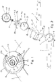
- figure 1 shows a middle section of an orthosis according to the invention without a cover with a first rail arm 1 and a second rail arm 2, with an axis element 5 being shown in section.
- the two rail arms 1, 2 are only shown in abbreviated form and have fastening devices, not shown, in particular Velcro strips, shells or the like, with which the rail arms 1, 2 can be attached in a known manner to limbs connected by means of a body joint, for example on the thigh and lower leg, upper - and lower arm, etc., can be attached.
- the rail arms 1, 2 are connected to one another in an articulated manner in a joint region 3 and can be pivoted about a pivot axis 4 relative to one another.
- the pivot axis 4 is formed by the axis element 5, which is fixed to the first rail arm 1.
- FIG 2 shows the structure of the orthosis according to the invention in an exploded view.
- the first rail arm 1 has an end region 6 in the shape of a circular disc with a central bore 7 .
- This bore 7 serves to accommodate a cylindrical section 8 ( figure 7 ) of the axis element 5 and for the passage of a central Screw 9 which can be screwed into an axial threaded bore 10 of the axle element 5 in order to connect the axle element 5 and the first rail arm 1 in a rotationally fixed manner.
- a plurality of pivoting range limiting holes 11 are provided, which are arranged on a circular arc concentric to the pivoting axis 4 .
- the orthosis also has a first friction-reducing disc 12, the second rail arm 2, a second friction-reducing disc 13, a perforated disc 14, two stop pin holders 15a, 15b, the axle element 5 and a cover 16, one after the other in the axial direction.
- the two friction-reducing disks 12, 13 are expediently made of plastic, in particular Teflon.
- the second rail arm 2 has an end area 17 with a bore 18 .
- the bore 18 serves to accommodate a cylindrical bearing sleeve 19 which is rotatably mounted on the cylindrical section 8 of the axle element 5 so that the second rail arm 2 can be pivoted about the pivot axis 4 relative to the first rail arm 1 .
- the end region 17 of the second rail arm 2 has a circumference 20 in the shape of a circular arc over approximately 180°.
- a radially projecting stop surface 21 adjoins this arcuate circumference 20 .
- the two friction-reducing discs 12, 13 have central holes 22, 23 which serve in the same way as the bore 18 for the bearing sleeve 19 to pass through.
- the perforated disk 14 is designed as a circular disk and is arranged parallel to the end region 6 of the first rail arm 1 at such a fixed distance that the second rail arm 2 can be pivoted between them. This distance is determined by the length of the cylindrical bearing sleeve 19 which rests with one end against a diameter step 25a formed by a polygonal section 25 of the axle element 5 and with its other end against the first rail arm 1 .
- the perforated disk 14 has a central opening 24 with a polygonal contour, which is used for non-rotatably slipping onto the correspondingly designed polygonal section 25 of the axle element 5 .
- the perforated disk 14 is non-rotatably connected to the first rail arm 1 by means of a screw connection (not shown) arranged in its edge region.
- a plurality of pivoting range limiting holes 26 are provided, which are aligned with the pivoting range limiting holes 11 of the first rail arm 1 and, like these, are arranged on a circular arc concentric to the pivoting axis 4 .
- the pivoting range limiting holes 11, 26 extend along an arc of a circle over approximately 270° and can be arranged, for example, in such a way that the angular distance between adjacent pivoting range limiting holes 11, 26 is 10° in each case.
- the pivoting range limiting holes 11, 26 are used to insert two stop pins 27a, 27b to limit the pivoting range of the orthosis in the extension and flexion direction.
- the stop pins 27a, 27b have a cylindrical insertion section 46 ( figure 4 ) which can be inserted parallel to the pivot axis 4 into an aligned pair of pivot range limiting holes 11, 26 up to a radially projecting collar 47.
- the pivoting range is limited in the extension direction by the stop surface 21 of the second rail arm 2 striking one of the stop pins 27a, 27b.
- the pivoting range is limited in the direction of flexion by a stop surface 28 of the second rail arm 2 striking the other stop pin 27b, 27a.
- the stop pins 27a, 27b are each held captive on the axle element 5 by a separate stop pin holder 15a, 15b.
- the two stop pin holders 15a, 15b are of the same design, but are arranged on the axle element 5 in a mirror-inverted manner.
- the two stop pin holders 15a, 15b are expediently arranged adjacent to the orthosis in the axial direction.
- Each stop pin holder 15a, 15b consists of a flat, thin leaf spring made of spring steel sheet, the thickness of which is expediently about 0.2 to 0.5 mm, in particular 0.3 mm. Other materials and thicknesses are possible.
- each stop pin holder 15a, 15b comprises an annular bearing section 30 with a central opening 31 for the passage of a cylindrical axle section 32 of the axle element 5 ( figure 7 ), on which the stop pin holder 15a, 15b is rotatably mounted.
- the two stop pin holders 15a, 15b can thus be rotated about the pivot axis 4 independently of one another.
- a resilient, elastically flexible holding arm 33 is connected to the annular bearing section 30, at the free end of which a pin fastening device 34 is provided for fastening the stop pin 27a, 27b.
- the holding arm 33 comprises a first arm section 35 which runs concentrically to the pivot axis 4 in a first circumferential direction over an angular range of approximately 110°.
- the first arm section 35 can have other lengths and, for example, extend over an angular range of 30-180°.
- the first arm portion 35 is separated from the bearing portion 30 by a gap 36 whose width is smaller than the width of the first arm portion 35 .
- the first arm section 35 transitions into a second arm section 38 by means of a 180° arc section 37, which also runs concentrically to the pivot axis 4, but in a second direction which is opposite to the first direction.
- the width of the gap 39 between the second arm section 38 and the first arm section 35 is again smaller than the width of the arm sections 35, 38.
- the second arm section 38 in the embodiment shown extends over an angular range of approximately 45-55°.
- the length of the second arm section 38 is variable to a large extent.
- the free end 4 of the holding arm 33, on which the stop pin 27a, 27b is attached can be lifted sufficiently far perpendicularly to the main plane of the stop pin holder 15a, 15b in order to pull the stop pin 27a, 27b completely out of the swivel range limiting holes 11, 26 and in one desired swivel range limitation hole 11, 26 to be able to use.
- stop pins 27a, 27b can only be pulled out of the swivel range limiting holes 11, 26 against the spring force of the stop pin holders 15a, 15b, the stop pin holders 15a, 15b simultaneously prevent an undesirable axial displacement or a loosening of the stop pins 27a, 27b from the swivel range limiting holes 11, 26 .
- the arranged at the free end 40 of the holding arm 33 pin attachment device 34 is formed in the illustrated embodiment as a releasable attachment device in the form of a clip connection for attaching the stop pin 27a, 27b.
- the pin fastening device 34 has an insertion hole 41 for inserting the stop pin 27a, 27b and spring or latching tongues 42 which fit into a peripheral groove 43 of the stop pin 27a, 27b ( figure 4 ) engage and thereby hold the stop pin 27a, 27b both radially and axially.
- the extend Spring or latching tongues 42 inward around the entire circumference of the insertion hole 41 and can be formed by radial incisions in the spring steel sheet at the edge.
- the plate- or bowl-shaped cover 16 can be designed in such a way that its peripheral wall 44 extends over the perforated disk 14 close to the first rail arm 1 .
- a lateral recess in the peripheral wall 44 creates the necessary free space for pivoting the second rail arm 2 over a maximum pivoting range of, for example, 120-160°, in particular about 140° relative to the first rail arm 1.
- this maximum pivoting range can vary widely.
- the cover 16 can be fastened to the axle element 5, to the perforated disk 14 and/or to the first swivel arm 1 in a wide variety of ways.
- the inside of the cover 16 expediently has a flat surface 45 which is at a predetermined, relatively small distance from the perforated disk 14 and holds the bearing sections 30 of the two stop pin holders 15a, 15b adjacent to the perforated disk 14 with little play and the stop pin holders 15a, 15b in an axial direction.
Landscapes
- Health & Medical Sciences (AREA)
- Nursing (AREA)
- Orthopedic Medicine & Surgery (AREA)
- Engineering & Computer Science (AREA)
- Biomedical Technology (AREA)
- Heart & Thoracic Surgery (AREA)
- Vascular Medicine (AREA)
- Life Sciences & Earth Sciences (AREA)
- Animal Behavior & Ethology (AREA)
- General Health & Medical Sciences (AREA)
- Public Health (AREA)
- Veterinary Medicine (AREA)
- Orthopedics, Nursing, And Contraception (AREA)
- Rehabilitation Tools (AREA)
Claims (8)
- Orthèse pourvue d'une première et d'une deuxième branche d'attelle (1, 2), qui sont reliées ensemble de manière articulée et sont pivotables l'une par rapport à l'autre dans une zone de pivotement déterminée, et pourvue d'un dispositif d'ajustement de la zone de pivotement, qui présente au moins une goupille de butée (27a, 27b) permettant la délimitation de la zone de pivotement, où la goupille de butée (27a, 27b) peut être placée au choix dans des trous de délimitation de la zone de pivotement (11, 26) de l'orthèse positionnés de manière diverse, caractérisée en ce que le dispositif d'ajustement de la zone de pivotement comprend au moins un support de goupille de butée (15a, 15b) souple qui présente une partie de palier (30) rotative autour d'un axe de pivotement (4) et une attelle de maintien (33) élastique sur laquelle la goupille de butée (27a, 27b) est fixée.
- Orthèse selon la revendication 1, caractérisée en ce que la partie de palier (30) est constituée d'une bague de palier qui est disposée autour de l'axe de pivotement (4) de l'orthèse en étant rotative autour.
- Orthèse selon la revendication 1 ou la revendication 2, caractérisée en ce que l'attelle de maintien (33) est conçue en forme de méandres, de S, d'U, de V ou de W.
- Orthèse selon la revendication 2 ou la revendication 3, caractérisée en ce que l'attelle de maintien (33) présente une première partie d'attelle (35), qui s'étend de manière concentrique par rapport à la bague de palier dans une première direction circonférentielle, et une deuxième partie d'attelle (38) qui s'étend de manière concentrique par rapport à la bague de palier dans une deuxième direction circonférentielle, qui est opposée à la première direction circonférentielle.
- Orthèse selon l'une des revendications précédentes, caractérisée en ce que l'attelle de maintien (33) est conçue sous forme d'un ressort à lames.
- Orthèse selon l'une des revendications précédentes, caractérisée en ce que l'attelle de maintien (33) présente un dispositif de fixation de goupille (34) amovible sous la forme d'une connexion par clip, pour la fixation de la goupille de butée (27a, 27b).
- Orthèse selon la revendication 4, caractérisée en ce que le dispositif de fixation de goupille (34) comprend un orifice d'insertion (41) permettant l'insertion de la goupille de butée (27a, 27b) et au moins une languette de ressort ou de butée (42), qui se met en prise dans une rainure circonférentielle (43) de la goupille de butée (27a, 27b).
- Orthèse selon l'une des revendications précédentes, caractérisée en ce que la partie de palier (30) et l'attelle de maintien (33) sont conçues en une pièce sous forme d'un élément en tôle élastique.
Applications Claiming Priority (2)
| Application Number | Priority Date | Filing Date | Title |
|---|---|---|---|
| DE102018105480.7A DE102018105480A1 (de) | 2018-03-09 | 2018-03-09 | Orthese mit Anschlagstifthalter |
| PCT/EP2019/055693 WO2019170803A1 (fr) | 2018-03-09 | 2019-03-07 | Orthèse à support de goupille de butée |
Publications (2)
| Publication Number | Publication Date |
|---|---|
| EP3761920A1 EP3761920A1 (fr) | 2021-01-13 |
| EP3761920B1 true EP3761920B1 (fr) | 2022-04-20 |
Family
ID=65729343
Family Applications (1)
| Application Number | Title | Priority Date | Filing Date |
|---|---|---|---|
| EP19710372.4A Active EP3761920B1 (fr) | 2018-03-09 | 2019-03-07 | Orthèse à support de goupille de butée |
Country Status (3)
| Country | Link |
|---|---|
| EP (1) | EP3761920B1 (fr) |
| DE (1) | DE102018105480A1 (fr) |
| WO (1) | WO2019170803A1 (fr) |
Families Citing this family (3)
| Publication number | Priority date | Publication date | Assignee | Title |
|---|---|---|---|---|
| IT201900017342A1 (it) * | 2019-09-26 | 2021-03-26 | Fgp Srl | Ortesi applicabile su arti superiori od inferiori provvista di accessorio adibito ad esercizi di prono-supinazione ad angolazione regolabile |
| DE102020001327A1 (de) * | 2020-02-28 | 2021-09-02 | Bernhard Sacherer | Orthesengelenk zum Bilden einer Funktionsstellung mit gefederter Auslenkung. |
| DE102023124508A1 (de) | 2023-09-12 | 2025-03-13 | Georg-August-Universität Göttingen Stiftung Öffentlichen Rechts | Exoskelett |
Family Cites Families (8)
| Publication number | Priority date | Publication date | Assignee | Title |
|---|---|---|---|---|
| US5292303A (en) * | 1992-07-01 | 1994-03-08 | Smith & Nephew Donjoy, Inc. | Hinged orthopedic brace having an adjustable pivot range |
| CA2186227C (fr) * | 1994-03-22 | 1999-09-28 | Mark Deharde | Attelle dynamique multifonctionnelle |
| US5672152A (en) * | 1995-11-28 | 1997-09-30 | Breg, Inc. | Hinge for an orthopedic brace having an adjustable range of rotation |
| DE19645076A1 (de) * | 1996-10-31 | 1998-05-14 | Albrecht Gmbh | Vorrichtung zur Reduktion von Streck- oder Beugedefiziten eines distalen Körperglieds gegenüber einem proximalen Körperglied |
| US7235059B2 (en) * | 2005-01-12 | 2007-06-26 | Breg, Inc. | Releasably locking hinge for an orthopedic brace having adjustable rotation limits |
| US7189212B2 (en) * | 2005-06-21 | 2007-03-13 | Bradley Lineberger | Orthopedic polycentric hinge |
| ITRM20130100A1 (it) * | 2013-02-21 | 2014-08-22 | Tecnoway S A S | Tutore per articolazione. |
| DE102015012321A1 (de) * | 2015-09-23 | 2017-03-23 | Albrecht Gmbh | Dynamische Gelenkstütze |
-
2018
- 2018-03-09 DE DE102018105480.7A patent/DE102018105480A1/de not_active Withdrawn
-
2019
- 2019-03-07 WO PCT/EP2019/055693 patent/WO2019170803A1/fr not_active Ceased
- 2019-03-07 EP EP19710372.4A patent/EP3761920B1/fr active Active
Also Published As
| Publication number | Publication date |
|---|---|
| WO2019170803A1 (fr) | 2019-09-12 |
| EP3761920A1 (fr) | 2021-01-13 |
| DE102018105480A1 (de) | 2019-09-12 |
Similar Documents
| Publication | Publication Date | Title |
|---|---|---|
| DE69409667T2 (de) | Scharniereinrichtung | |
| DE3000691C2 (de) | Haltevorrichtung | |
| EP3658336B1 (fr) | Dispositif de retenu à crochets pour une machine-outil | |
| DE3229116A1 (de) | Foerderband-reinigungsvorrichtung | |
| EP0699419A2 (fr) | Fixateur ostéosynthétique | |
| DE3213470C2 (fr) | ||
| EP2231082B1 (fr) | Articulation avec correction | |
| EP3761920B1 (fr) | Orthèse à support de goupille de butée | |
| DE1300470B (de) | Verstellbare Halterungsvorrichtung | |
| DE19707629A1 (de) | Scharnier | |
| DE102012011848A1 (de) | Befestigungsanordnung | |
| EP1180381A1 (fr) | Cathéter intraveineux muni d'une gaine de protection | |
| EP3746665B1 (fr) | Ferrure de meuble | |
| EP3199404B1 (fr) | Couvercle, bac de rangement comprenant un couvercle et outil de montage | |
| DE2847060C3 (de) | Halterung eines Gesichtsschildes an einem Schutzhelm | |
| DE102019101273B4 (de) | Befestigungsvorrichtung zum Halten eines Sensors und Verfahren zum Befestigen und Justieren eines Sensors | |
| CH649020A5 (en) | Chuck for taps | |
| DE102010008491B4 (de) | Vorrichtung zur Führung einer medizinischen Kanüle an einem Ultraschallkopf | |
| DE102006016213B4 (de) | Chirurgische Verbindungsvorrichtung und chirurgische Vorrichtung | |
| EP3738534B1 (fr) | Dispositif de fixation des os | |
| EP3761921B1 (fr) | Orthèse pourvue d'un couvercle pouvant être fixé sans outils | |
| DE202015003640U1 (de) | Fernoptische Einrichtung mit einer Halterung für einen Riemen | |
| EP0614037A1 (fr) | Support fixé au plafond | |
| DE3733126A1 (de) | Schwenklagerung, insbesondere fuer tuerhaltebaender an kraftwagentueren | |
| DE202006005629U1 (de) | Chirurgische Verbindungsvorrichtung und chirurgische Vorrichtung |
Legal Events
| Date | Code | Title | Description |
|---|---|---|---|
| STAA | Information on the status of an ep patent application or granted ep patent |
Free format text: STATUS: UNKNOWN |
|
| STAA | Information on the status of an ep patent application or granted ep patent |
Free format text: STATUS: THE INTERNATIONAL PUBLICATION HAS BEEN MADE |
|
| PUAI | Public reference made under article 153(3) epc to a published international application that has entered the european phase |
Free format text: ORIGINAL CODE: 0009012 |
|
| STAA | Information on the status of an ep patent application or granted ep patent |
Free format text: STATUS: REQUEST FOR EXAMINATION WAS MADE |
|
| 17P | Request for examination filed |
Effective date: 20200916 |
|
| AK | Designated contracting states |
Kind code of ref document: A1 Designated state(s): AL AT BE BG CH CY CZ DE DK EE ES FI FR GB GR HR HU IE IS IT LI LT LU LV MC MK MT NL NO PL PT RO RS SE SI SK SM TR |
|
| AX | Request for extension of the european patent |
Extension state: BA ME |
|
| DAV | Request for validation of the european patent (deleted) | ||
| DAX | Request for extension of the european patent (deleted) | ||
| GRAP | Despatch of communication of intention to grant a patent |
Free format text: ORIGINAL CODE: EPIDOSNIGR1 |
|
| STAA | Information on the status of an ep patent application or granted ep patent |
Free format text: STATUS: GRANT OF PATENT IS INTENDED |
|
| INTG | Intention to grant announced |
Effective date: 20211116 |
|
| GRAS | Grant fee paid |
Free format text: ORIGINAL CODE: EPIDOSNIGR3 |
|
| GRAA | (expected) grant |
Free format text: ORIGINAL CODE: 0009210 |
|
| STAA | Information on the status of an ep patent application or granted ep patent |
Free format text: STATUS: THE PATENT HAS BEEN GRANTED |
|
| AK | Designated contracting states |
Kind code of ref document: B1 Designated state(s): AL AT BE BG CH CY CZ DE DK EE ES FI FR GB GR HR HU IE IS IT LI LT LU LV MC MK MT NL NO PL PT RO RS SE SI SK SM TR |
|
| REG | Reference to a national code |
Ref country code: GB Ref legal event code: FG4D Free format text: NOT ENGLISH |
|
| REG | Reference to a national code |
Ref country code: CH Ref legal event code: EP |
|
| REG | Reference to a national code |
Ref country code: IE Ref legal event code: FG4D Free format text: LANGUAGE OF EP DOCUMENT: GERMAN |
|
| REG | Reference to a national code |
Ref country code: DE Ref legal event code: R096 Ref document number: 502019004124 Country of ref document: DE |
|
| REG | Reference to a national code |
Ref country code: AT Ref legal event code: REF Ref document number: 1484605 Country of ref document: AT Kind code of ref document: T Effective date: 20220515 |
|
| REG | Reference to a national code |
Ref country code: LT Ref legal event code: MG9D |
|
| REG | Reference to a national code |
Ref country code: NL Ref legal event code: MP Effective date: 20220420 |
|
| PG25 | Lapsed in a contracting state [announced via postgrant information from national office to epo] |
Ref country code: NL Free format text: LAPSE BECAUSE OF FAILURE TO SUBMIT A TRANSLATION OF THE DESCRIPTION OR TO PAY THE FEE WITHIN THE PRESCRIBED TIME-LIMIT Effective date: 20220420 |
|
| PG25 | Lapsed in a contracting state [announced via postgrant information from national office to epo] |
Ref country code: SE Free format text: LAPSE BECAUSE OF FAILURE TO SUBMIT A TRANSLATION OF THE DESCRIPTION OR TO PAY THE FEE WITHIN THE PRESCRIBED TIME-LIMIT Effective date: 20220420 Ref country code: PT Free format text: LAPSE BECAUSE OF FAILURE TO SUBMIT A TRANSLATION OF THE DESCRIPTION OR TO PAY THE FEE WITHIN THE PRESCRIBED TIME-LIMIT Effective date: 20220822 Ref country code: NO Free format text: LAPSE BECAUSE OF FAILURE TO SUBMIT A TRANSLATION OF THE DESCRIPTION OR TO PAY THE FEE WITHIN THE PRESCRIBED TIME-LIMIT Effective date: 20220720 Ref country code: LT Free format text: LAPSE BECAUSE OF FAILURE TO SUBMIT A TRANSLATION OF THE DESCRIPTION OR TO PAY THE FEE WITHIN THE PRESCRIBED TIME-LIMIT Effective date: 20220420 Ref country code: HR Free format text: LAPSE BECAUSE OF FAILURE TO SUBMIT A TRANSLATION OF THE DESCRIPTION OR TO PAY THE FEE WITHIN THE PRESCRIBED TIME-LIMIT Effective date: 20220420 Ref country code: GR Free format text: LAPSE BECAUSE OF FAILURE TO SUBMIT A TRANSLATION OF THE DESCRIPTION OR TO PAY THE FEE WITHIN THE PRESCRIBED TIME-LIMIT Effective date: 20220721 Ref country code: FI Free format text: LAPSE BECAUSE OF FAILURE TO SUBMIT A TRANSLATION OF THE DESCRIPTION OR TO PAY THE FEE WITHIN THE PRESCRIBED TIME-LIMIT Effective date: 20220420 Ref country code: ES Free format text: LAPSE BECAUSE OF FAILURE TO SUBMIT A TRANSLATION OF THE DESCRIPTION OR TO PAY THE FEE WITHIN THE PRESCRIBED TIME-LIMIT Effective date: 20220420 Ref country code: BG Free format text: LAPSE BECAUSE OF FAILURE TO SUBMIT A TRANSLATION OF THE DESCRIPTION OR TO PAY THE FEE WITHIN THE PRESCRIBED TIME-LIMIT Effective date: 20220720 |
|
| PG25 | Lapsed in a contracting state [announced via postgrant information from national office to epo] |
Ref country code: RS Free format text: LAPSE BECAUSE OF FAILURE TO SUBMIT A TRANSLATION OF THE DESCRIPTION OR TO PAY THE FEE WITHIN THE PRESCRIBED TIME-LIMIT Effective date: 20220420 Ref country code: PL Free format text: LAPSE BECAUSE OF FAILURE TO SUBMIT A TRANSLATION OF THE DESCRIPTION OR TO PAY THE FEE WITHIN THE PRESCRIBED TIME-LIMIT Effective date: 20220420 Ref country code: LV Free format text: LAPSE BECAUSE OF FAILURE TO SUBMIT A TRANSLATION OF THE DESCRIPTION OR TO PAY THE FEE WITHIN THE PRESCRIBED TIME-LIMIT Effective date: 20220420 Ref country code: IS Free format text: LAPSE BECAUSE OF FAILURE TO SUBMIT A TRANSLATION OF THE DESCRIPTION OR TO PAY THE FEE WITHIN THE PRESCRIBED TIME-LIMIT Effective date: 20220820 |
|
| REG | Reference to a national code |
Ref country code: DE Ref legal event code: R097 Ref document number: 502019004124 Country of ref document: DE |
|
| PG25 | Lapsed in a contracting state [announced via postgrant information from national office to epo] |
Ref country code: SM Free format text: LAPSE BECAUSE OF FAILURE TO SUBMIT A TRANSLATION OF THE DESCRIPTION OR TO PAY THE FEE WITHIN THE PRESCRIBED TIME-LIMIT Effective date: 20220420 Ref country code: SK Free format text: LAPSE BECAUSE OF FAILURE TO SUBMIT A TRANSLATION OF THE DESCRIPTION OR TO PAY THE FEE WITHIN THE PRESCRIBED TIME-LIMIT Effective date: 20220420 Ref country code: RO Free format text: LAPSE BECAUSE OF FAILURE TO SUBMIT A TRANSLATION OF THE DESCRIPTION OR TO PAY THE FEE WITHIN THE PRESCRIBED TIME-LIMIT Effective date: 20220420 Ref country code: EE Free format text: LAPSE BECAUSE OF FAILURE TO SUBMIT A TRANSLATION OF THE DESCRIPTION OR TO PAY THE FEE WITHIN THE PRESCRIBED TIME-LIMIT Effective date: 20220420 Ref country code: DK Free format text: LAPSE BECAUSE OF FAILURE TO SUBMIT A TRANSLATION OF THE DESCRIPTION OR TO PAY THE FEE WITHIN THE PRESCRIBED TIME-LIMIT Effective date: 20220420 Ref country code: CZ Free format text: LAPSE BECAUSE OF FAILURE TO SUBMIT A TRANSLATION OF THE DESCRIPTION OR TO PAY THE FEE WITHIN THE PRESCRIBED TIME-LIMIT Effective date: 20220420 |
|
| PLBE | No opposition filed within time limit |
Free format text: ORIGINAL CODE: 0009261 |
|
| STAA | Information on the status of an ep patent application or granted ep patent |
Free format text: STATUS: NO OPPOSITION FILED WITHIN TIME LIMIT |
|
| 26N | No opposition filed |
Effective date: 20230123 |
|
| PG25 | Lapsed in a contracting state [announced via postgrant information from national office to epo] |
Ref country code: AL Free format text: LAPSE BECAUSE OF FAILURE TO SUBMIT A TRANSLATION OF THE DESCRIPTION OR TO PAY THE FEE WITHIN THE PRESCRIBED TIME-LIMIT Effective date: 20220420 |
|
| PG25 | Lapsed in a contracting state [announced via postgrant information from national office to epo] |
Ref country code: SI Free format text: LAPSE BECAUSE OF FAILURE TO SUBMIT A TRANSLATION OF THE DESCRIPTION OR TO PAY THE FEE WITHIN THE PRESCRIBED TIME-LIMIT Effective date: 20220420 |
|
| P01 | Opt-out of the competence of the unified patent court (upc) registered |
Effective date: 20230524 |
|
| PG25 | Lapsed in a contracting state [announced via postgrant information from national office to epo] |
Ref country code: MC Free format text: LAPSE BECAUSE OF FAILURE TO SUBMIT A TRANSLATION OF THE DESCRIPTION OR TO PAY THE FEE WITHIN THE PRESCRIBED TIME-LIMIT Effective date: 20220420 |
|
| REG | Reference to a national code |
Ref country code: CH Ref legal event code: PL |
|
| REG | Reference to a national code |
Ref country code: BE Ref legal event code: MM Effective date: 20230331 |
|
| PG25 | Lapsed in a contracting state [announced via postgrant information from national office to epo] |
Ref country code: LU Free format text: LAPSE BECAUSE OF NON-PAYMENT OF DUE FEES Effective date: 20230307 |
|
| REG | Reference to a national code |
Ref country code: IE Ref legal event code: MM4A |
|
| PG25 | Lapsed in a contracting state [announced via postgrant information from national office to epo] |
Ref country code: LI Free format text: LAPSE BECAUSE OF NON-PAYMENT OF DUE FEES Effective date: 20230331 Ref country code: IT Free format text: LAPSE BECAUSE OF FAILURE TO SUBMIT A TRANSLATION OF THE DESCRIPTION OR TO PAY THE FEE WITHIN THE PRESCRIBED TIME-LIMIT Effective date: 20220420 Ref country code: IE Free format text: LAPSE BECAUSE OF NON-PAYMENT OF DUE FEES Effective date: 20230307 Ref country code: CH Free format text: LAPSE BECAUSE OF NON-PAYMENT OF DUE FEES Effective date: 20230331 |
|
| PG25 | Lapsed in a contracting state [announced via postgrant information from national office to epo] |
Ref country code: BE Free format text: LAPSE BECAUSE OF NON-PAYMENT OF DUE FEES Effective date: 20230331 |
|
| PG25 | Lapsed in a contracting state [announced via postgrant information from national office to epo] |
Ref country code: BG Free format text: LAPSE BECAUSE OF FAILURE TO SUBMIT A TRANSLATION OF THE DESCRIPTION OR TO PAY THE FEE WITHIN THE PRESCRIBED TIME-LIMIT Effective date: 20220420 |
|
| PG25 | Lapsed in a contracting state [announced via postgrant information from national office to epo] |
Ref country code: BG Free format text: LAPSE BECAUSE OF FAILURE TO SUBMIT A TRANSLATION OF THE DESCRIPTION OR TO PAY THE FEE WITHIN THE PRESCRIBED TIME-LIMIT Effective date: 20220420 |
|
| REG | Reference to a national code |
Ref country code: AT Ref legal event code: MM01 Ref document number: 1484605 Country of ref document: AT Kind code of ref document: T Effective date: 20240307 |
|
| PG25 | Lapsed in a contracting state [announced via postgrant information from national office to epo] |
Ref country code: AT Free format text: LAPSE BECAUSE OF NON-PAYMENT OF DUE FEES Effective date: 20240307 |
|
| PG25 | Lapsed in a contracting state [announced via postgrant information from national office to epo] |
Ref country code: CY Free format text: LAPSE BECAUSE OF FAILURE TO SUBMIT A TRANSLATION OF THE DESCRIPTION OR TO PAY THE FEE WITHIN THE PRESCRIBED TIME-LIMIT; INVALID AB INITIO Effective date: 20190307 |
|
| PG25 | Lapsed in a contracting state [announced via postgrant information from national office to epo] |
Ref country code: HU Free format text: LAPSE BECAUSE OF FAILURE TO SUBMIT A TRANSLATION OF THE DESCRIPTION OR TO PAY THE FEE WITHIN THE PRESCRIBED TIME-LIMIT; INVALID AB INITIO Effective date: 20190307 |
|
| PG25 | Lapsed in a contracting state [announced via postgrant information from national office to epo] |
Ref country code: TR Free format text: LAPSE BECAUSE OF FAILURE TO SUBMIT A TRANSLATION OF THE DESCRIPTION OR TO PAY THE FEE WITHIN THE PRESCRIBED TIME-LIMIT Effective date: 20220420 |
|
| PGFP | Annual fee paid to national office [announced via postgrant information from national office to epo] |
Ref country code: GB Payment date: 20260324 Year of fee payment: 8 |
|
| PGFP | Annual fee paid to national office [announced via postgrant information from national office to epo] |
Ref country code: DE Payment date: 20260320 Year of fee payment: 8 |
|
| PGFP | Annual fee paid to national office [announced via postgrant information from national office to epo] |
Ref country code: AT Payment date: 20260410 Year of fee payment: 5 |
|
| PGFP | Annual fee paid to national office [announced via postgrant information from national office to epo] |
Ref country code: FR Payment date: 20260324 Year of fee payment: 8 |