EP3762061B1 - Tube médical tolérant au pliage et à la compression - Google Patents
Tube médical tolérant au pliage et à la compression Download PDFInfo
- Publication number
- EP3762061B1 EP3762061B1 EP19722357.1A EP19722357A EP3762061B1 EP 3762061 B1 EP3762061 B1 EP 3762061B1 EP 19722357 A EP19722357 A EP 19722357A EP 3762061 B1 EP3762061 B1 EP 3762061B1
- Authority
- EP
- European Patent Office
- Prior art keywords
- tube
- tubing
- jaws
- tubing system
- medical tubing
- Prior art date
- Legal status (The legal status is an assumption and is not a legal conclusion. Google has not performed a legal analysis and makes no representation as to the accuracy of the status listed.)
- Active
Links
Images


Classifications
-
- A—HUMAN NECESSITIES
- A61—MEDICAL OR VETERINARY SCIENCE; HYGIENE
- A61M—DEVICES FOR INTRODUCING MEDIA INTO, OR ONTO, THE BODY; DEVICES FOR TRANSDUCING BODY MEDIA OR FOR TAKING MEDIA FROM THE BODY; DEVICES FOR PRODUCING OR ENDING SLEEP OR STUPOR
- A61M25/00—Catheters; Hollow probes
- A61M25/0043—Catheters; Hollow probes characterised by structural features
-
- A—HUMAN NECESSITIES
- A61—MEDICAL OR VETERINARY SCIENCE; HYGIENE
- A61M—DEVICES FOR INTRODUCING MEDIA INTO, OR ONTO, THE BODY; DEVICES FOR TRANSDUCING BODY MEDIA OR FOR TAKING MEDIA FROM THE BODY; DEVICES FOR PRODUCING OR ENDING SLEEP OR STUPOR
- A61M1/00—Suction or pumping devices for medical purposes; Devices for carrying-off, for treatment of, or for carrying-over, body-liquids; Drainage systems
- A61M1/14—Dialysis systems; Artificial kidneys; Blood oxygenators ; Reciprocating systems for treatment of body fluids, e.g. single needle systems for hemofiltration or pheresis
- A61M1/16—Dialysis systems; Artificial kidneys; Blood oxygenators ; Reciprocating systems for treatment of body fluids, e.g. single needle systems for hemofiltration or pheresis with membranes
-
- A—HUMAN NECESSITIES
- A61—MEDICAL OR VETERINARY SCIENCE; HYGIENE
- A61M—DEVICES FOR INTRODUCING MEDIA INTO, OR ONTO, THE BODY; DEVICES FOR TRANSDUCING BODY MEDIA OR FOR TAKING MEDIA FROM THE BODY; DEVICES FOR PRODUCING OR ENDING SLEEP OR STUPOR
- A61M1/00—Suction or pumping devices for medical purposes; Devices for carrying-off, for treatment of, or for carrying-over, body-liquids; Drainage systems
- A61M1/14—Dialysis systems; Artificial kidneys; Blood oxygenators ; Reciprocating systems for treatment of body fluids, e.g. single needle systems for hemofiltration or pheresis
- A61M1/15—Dialysis systems; Artificial kidneys; Blood oxygenators ; Reciprocating systems for treatment of body fluids, e.g. single needle systems for hemofiltration or pheresis with a cassette forming partially or totally the flow circuit for the treating fluid, e.g. the dialysate fluid circuit or the treating gas circuit
- A61M1/152—Details related to the interface between cassette and machine
- A61M1/1524—Details related to the interface between cassette and machine the interface providing means for actuating on functional elements of the cassette, e.g. plungers
-
- A—HUMAN NECESSITIES
- A61—MEDICAL OR VETERINARY SCIENCE; HYGIENE
- A61M—DEVICES FOR INTRODUCING MEDIA INTO, OR ONTO, THE BODY; DEVICES FOR TRANSDUCING BODY MEDIA OR FOR TAKING MEDIA FROM THE BODY; DEVICES FOR PRODUCING OR ENDING SLEEP OR STUPOR
- A61M1/00—Suction or pumping devices for medical purposes; Devices for carrying-off, for treatment of, or for carrying-over, body-liquids; Drainage systems
- A61M1/14—Dialysis systems; Artificial kidneys; Blood oxygenators ; Reciprocating systems for treatment of body fluids, e.g. single needle systems for hemofiltration or pheresis
- A61M1/15—Dialysis systems; Artificial kidneys; Blood oxygenators ; Reciprocating systems for treatment of body fluids, e.g. single needle systems for hemofiltration or pheresis with a cassette forming partially or totally the flow circuit for the treating fluid, e.g. the dialysate fluid circuit or the treating gas circuit
- A61M1/153—Dialysis systems; Artificial kidneys; Blood oxygenators ; Reciprocating systems for treatment of body fluids, e.g. single needle systems for hemofiltration or pheresis with a cassette forming partially or totally the flow circuit for the treating fluid, e.g. the dialysate fluid circuit or the treating gas circuit the cassette being adapted for heating or cooling the treating fluid, e.g. the dialysate or the treating gas
-
- A—HUMAN NECESSITIES
- A61—MEDICAL OR VETERINARY SCIENCE; HYGIENE
- A61M—DEVICES FOR INTRODUCING MEDIA INTO, OR ONTO, THE BODY; DEVICES FOR TRANSDUCING BODY MEDIA OR FOR TAKING MEDIA FROM THE BODY; DEVICES FOR PRODUCING OR ENDING SLEEP OR STUPOR
- A61M1/00—Suction or pumping devices for medical purposes; Devices for carrying-off, for treatment of, or for carrying-over, body-liquids; Drainage systems
- A61M1/14—Dialysis systems; Artificial kidneys; Blood oxygenators ; Reciprocating systems for treatment of body fluids, e.g. single needle systems for hemofiltration or pheresis
- A61M1/15—Dialysis systems; Artificial kidneys; Blood oxygenators ; Reciprocating systems for treatment of body fluids, e.g. single needle systems for hemofiltration or pheresis with a cassette forming partially or totally the flow circuit for the treating fluid, e.g. the dialysate fluid circuit or the treating gas circuit
- A61M1/154—Dialysis systems; Artificial kidneys; Blood oxygenators ; Reciprocating systems for treatment of body fluids, e.g. single needle systems for hemofiltration or pheresis with a cassette forming partially or totally the flow circuit for the treating fluid, e.g. the dialysate fluid circuit or the treating gas circuit with sensing means or components thereof
-
- A—HUMAN NECESSITIES
- A61—MEDICAL OR VETERINARY SCIENCE; HYGIENE
- A61M—DEVICES FOR INTRODUCING MEDIA INTO, OR ONTO, THE BODY; DEVICES FOR TRANSDUCING BODY MEDIA OR FOR TAKING MEDIA FROM THE BODY; DEVICES FOR PRODUCING OR ENDING SLEEP OR STUPOR
- A61M1/00—Suction or pumping devices for medical purposes; Devices for carrying-off, for treatment of, or for carrying-over, body-liquids; Drainage systems
- A61M1/14—Dialysis systems; Artificial kidneys; Blood oxygenators ; Reciprocating systems for treatment of body fluids, e.g. single needle systems for hemofiltration or pheresis
- A61M1/15—Dialysis systems; Artificial kidneys; Blood oxygenators ; Reciprocating systems for treatment of body fluids, e.g. single needle systems for hemofiltration or pheresis with a cassette forming partially or totally the flow circuit for the treating fluid, e.g. the dialysate fluid circuit or the treating gas circuit
- A61M1/155—Dialysis systems; Artificial kidneys; Blood oxygenators ; Reciprocating systems for treatment of body fluids, e.g. single needle systems for hemofiltration or pheresis with a cassette forming partially or totally the flow circuit for the treating fluid, e.g. the dialysate fluid circuit or the treating gas circuit with treatment-fluid pumping means or components thereof
-
- A—HUMAN NECESSITIES
- A61—MEDICAL OR VETERINARY SCIENCE; HYGIENE
- A61M—DEVICES FOR INTRODUCING MEDIA INTO, OR ONTO, THE BODY; DEVICES FOR TRANSDUCING BODY MEDIA OR FOR TAKING MEDIA FROM THE BODY; DEVICES FOR PRODUCING OR ENDING SLEEP OR STUPOR
- A61M1/00—Suction or pumping devices for medical purposes; Devices for carrying-off, for treatment of, or for carrying-over, body-liquids; Drainage systems
- A61M1/14—Dialysis systems; Artificial kidneys; Blood oxygenators ; Reciprocating systems for treatment of body fluids, e.g. single needle systems for hemofiltration or pheresis
- A61M1/15—Dialysis systems; Artificial kidneys; Blood oxygenators ; Reciprocating systems for treatment of body fluids, e.g. single needle systems for hemofiltration or pheresis with a cassette forming partially or totally the flow circuit for the treating fluid, e.g. the dialysate fluid circuit or the treating gas circuit
- A61M1/156—Constructional details of the cassette, e.g. specific details on material or shape
- A61M1/1561—Constructional details of the cassette, e.g. specific details on material or shape at least one cassette surface or portion thereof being flexible, e.g. the cassette having a rigid base portion with preformed channels and being covered with a foil
-
- A—HUMAN NECESSITIES
- A61—MEDICAL OR VETERINARY SCIENCE; HYGIENE
- A61M—DEVICES FOR INTRODUCING MEDIA INTO, OR ONTO, THE BODY; DEVICES FOR TRANSDUCING BODY MEDIA OR FOR TAKING MEDIA FROM THE BODY; DEVICES FOR PRODUCING OR ENDING SLEEP OR STUPOR
- A61M1/00—Suction or pumping devices for medical purposes; Devices for carrying-off, for treatment of, or for carrying-over, body-liquids; Drainage systems
- A61M1/14—Dialysis systems; Artificial kidneys; Blood oxygenators ; Reciprocating systems for treatment of body fluids, e.g. single needle systems for hemofiltration or pheresis
- A61M1/15—Dialysis systems; Artificial kidneys; Blood oxygenators ; Reciprocating systems for treatment of body fluids, e.g. single needle systems for hemofiltration or pheresis with a cassette forming partially or totally the flow circuit for the treating fluid, e.g. the dialysate fluid circuit or the treating gas circuit
- A61M1/156—Constructional details of the cassette, e.g. specific details on material or shape
- A61M1/1565—Details of valves
-
- A—HUMAN NECESSITIES
- A61—MEDICAL OR VETERINARY SCIENCE; HYGIENE
- A61M—DEVICES FOR INTRODUCING MEDIA INTO, OR ONTO, THE BODY; DEVICES FOR TRANSDUCING BODY MEDIA OR FOR TAKING MEDIA FROM THE BODY; DEVICES FOR PRODUCING OR ENDING SLEEP OR STUPOR
- A61M1/00—Suction or pumping devices for medical purposes; Devices for carrying-off, for treatment of, or for carrying-over, body-liquids; Drainage systems
- A61M1/14—Dialysis systems; Artificial kidneys; Blood oxygenators ; Reciprocating systems for treatment of body fluids, e.g. single needle systems for hemofiltration or pheresis
- A61M1/15—Dialysis systems; Artificial kidneys; Blood oxygenators ; Reciprocating systems for treatment of body fluids, e.g. single needle systems for hemofiltration or pheresis with a cassette forming partially or totally the flow circuit for the treating fluid, e.g. the dialysate fluid circuit or the treating gas circuit
- A61M1/159—Dialysis systems; Artificial kidneys; Blood oxygenators ; Reciprocating systems for treatment of body fluids, e.g. single needle systems for hemofiltration or pheresis with a cassette forming partially or totally the flow circuit for the treating fluid, e.g. the dialysate fluid circuit or the treating gas circuit specially adapted for peritoneal dialysis
-
- A—HUMAN NECESSITIES
- A61—MEDICAL OR VETERINARY SCIENCE; HYGIENE
- A61M—DEVICES FOR INTRODUCING MEDIA INTO, OR ONTO, THE BODY; DEVICES FOR TRANSDUCING BODY MEDIA OR FOR TAKING MEDIA FROM THE BODY; DEVICES FOR PRODUCING OR ENDING SLEEP OR STUPOR
- A61M1/00—Suction or pumping devices for medical purposes; Devices for carrying-off, for treatment of, or for carrying-over, body-liquids; Drainage systems
- A61M1/14—Dialysis systems; Artificial kidneys; Blood oxygenators ; Reciprocating systems for treatment of body fluids, e.g. single needle systems for hemofiltration or pheresis
- A61M1/28—Peritoneal dialysis ; Other peritoneal treatment, e.g. oxygenation
- A61M1/285—Catheters therefor
-
- A—HUMAN NECESSITIES
- A61—MEDICAL OR VETERINARY SCIENCE; HYGIENE
- A61M—DEVICES FOR INTRODUCING MEDIA INTO, OR ONTO, THE BODY; DEVICES FOR TRANSDUCING BODY MEDIA OR FOR TAKING MEDIA FROM THE BODY; DEVICES FOR PRODUCING OR ENDING SLEEP OR STUPOR
- A61M39/00—Tubes, tube connectors, tube couplings, valves, access sites or the like, specially adapted for medical use
- A61M39/08—Tubes; Storage means specially adapted therefor
-
- A—HUMAN NECESSITIES
- A61—MEDICAL OR VETERINARY SCIENCE; HYGIENE
- A61M—DEVICES FOR INTRODUCING MEDIA INTO, OR ONTO, THE BODY; DEVICES FOR TRANSDUCING BODY MEDIA OR FOR TAKING MEDIA FROM THE BODY; DEVICES FOR PRODUCING OR ENDING SLEEP OR STUPOR
- A61M39/00—Tubes, tube connectors, tube couplings, valves, access sites or the like, specially adapted for medical use
- A61M39/22—Valves or arrangement of valves
- A61M39/28—Clamping means for squeezing flexible tubes, e.g. roller clamps
- A61M39/283—Screw clamps
-
- F—MECHANICAL ENGINEERING; LIGHTING; HEATING; WEAPONS; BLASTING
- F16—ENGINEERING ELEMENTS AND UNITS; GENERAL MEASURES FOR PRODUCING AND MAINTAINING EFFECTIVE FUNCTIONING OF MACHINES OR INSTALLATIONS; THERMAL INSULATION IN GENERAL
- F16L—PIPES; JOINTS OR FITTINGS FOR PIPES; SUPPORTS FOR PIPES, CABLES OR PROTECTIVE TUBING; MEANS FOR THERMAL INSULATION IN GENERAL
- F16L11/00—Hoses, i.e. flexible pipes
- F16L11/04—Hoses, i.e. flexible pipes made of rubber or flexible plastics
- F16L11/12—Hoses, i.e. flexible pipes made of rubber or flexible plastics with arrangements for particular purposes, e.g. specially profiled, with protecting layer, heated, electrically conducting
- F16L11/121—Hoses, i.e. flexible pipes made of rubber or flexible plastics with arrangements for particular purposes, e.g. specially profiled, with protecting layer, heated, electrically conducting specially profiled cross sections
-
- F—MECHANICAL ENGINEERING; LIGHTING; HEATING; WEAPONS; BLASTING
- F16—ENGINEERING ELEMENTS AND UNITS; GENERAL MEASURES FOR PRODUCING AND MAINTAINING EFFECTIVE FUNCTIONING OF MACHINES OR INSTALLATIONS; THERMAL INSULATION IN GENERAL
- F16L—PIPES; JOINTS OR FITTINGS FOR PIPES; SUPPORTS FOR PIPES, CABLES OR PROTECTIVE TUBING; MEANS FOR THERMAL INSULATION IN GENERAL
- F16L55/00—Devices or appurtenances for use in, or in connection with, pipes or pipe systems
- F16L55/10—Means for stopping flow in pipes or hoses
-
- A—HUMAN NECESSITIES
- A61—MEDICAL OR VETERINARY SCIENCE; HYGIENE
- A61M—DEVICES FOR INTRODUCING MEDIA INTO, OR ONTO, THE BODY; DEVICES FOR TRANSDUCING BODY MEDIA OR FOR TAKING MEDIA FROM THE BODY; DEVICES FOR PRODUCING OR ENDING SLEEP OR STUPOR
- A61M1/00—Suction or pumping devices for medical purposes; Devices for carrying-off, for treatment of, or for carrying-over, body-liquids; Drainage systems
- A61M1/14—Dialysis systems; Artificial kidneys; Blood oxygenators ; Reciprocating systems for treatment of body fluids, e.g. single needle systems for hemofiltration or pheresis
- A61M1/15—Dialysis systems; Artificial kidneys; Blood oxygenators ; Reciprocating systems for treatment of body fluids, e.g. single needle systems for hemofiltration or pheresis with a cassette forming partially or totally the flow circuit for the treating fluid, e.g. the dialysate fluid circuit or the treating gas circuit
- A61M1/156—Constructional details of the cassette, e.g. specific details on material or shape
- A61M1/1562—Details of incorporated reservoirs
-
- A—HUMAN NECESSITIES
- A61—MEDICAL OR VETERINARY SCIENCE; HYGIENE
- A61M—DEVICES FOR INTRODUCING MEDIA INTO, OR ONTO, THE BODY; DEVICES FOR TRANSDUCING BODY MEDIA OR FOR TAKING MEDIA FROM THE BODY; DEVICES FOR PRODUCING OR ENDING SLEEP OR STUPOR
- A61M25/00—Catheters; Hollow probes
- A61M25/0021—Catheters; Hollow probes characterised by the form of the tubing
- A61M25/0023—Catheters; Hollow probes characterised by the form of the tubing by the form of the lumen, e.g. cross-section, variable diameter
- A61M25/0026—Multi-lumen catheters with stationary elements
- A61M25/003—Multi-lumen catheters with stationary elements characterized by features relating to least one lumen located at the distal part of the catheter, e.g. filters, plugs or valves
- A61M2025/0031—Multi-lumen catheters with stationary elements characterized by features relating to least one lumen located at the distal part of the catheter, e.g. filters, plugs or valves characterized by lumina for withdrawing or delivering, i.e. used for extracorporeal circuit treatment
-
- A—HUMAN NECESSITIES
- A61—MEDICAL OR VETERINARY SCIENCE; HYGIENE
- A61M—DEVICES FOR INTRODUCING MEDIA INTO, OR ONTO, THE BODY; DEVICES FOR TRANSDUCING BODY MEDIA OR FOR TAKING MEDIA FROM THE BODY; DEVICES FOR PRODUCING OR ENDING SLEEP OR STUPOR
- A61M25/00—Catheters; Hollow probes
- A61M25/0043—Catheters; Hollow probes characterised by structural features
- A61M2025/0059—Catheters; Hollow probes characterised by structural features having means for preventing the catheter, sheath or lumens from collapsing due to outer forces, e.g. compressing forces, or caused by twisting or kinking
-
- A—HUMAN NECESSITIES
- A61—MEDICAL OR VETERINARY SCIENCE; HYGIENE
- A61M—DEVICES FOR INTRODUCING MEDIA INTO, OR ONTO, THE BODY; DEVICES FOR TRANSDUCING BODY MEDIA OR FOR TAKING MEDIA FROM THE BODY; DEVICES FOR PRODUCING OR ENDING SLEEP OR STUPOR
- A61M2205/00—General characteristics of the apparatus
- A61M2205/12—General characteristics of the apparatus with interchangeable cassettes forming partially or totally the fluid circuit
-
- A—HUMAN NECESSITIES
- A61—MEDICAL OR VETERINARY SCIENCE; HYGIENE
- A61M—DEVICES FOR INTRODUCING MEDIA INTO, OR ONTO, THE BODY; DEVICES FOR TRANSDUCING BODY MEDIA OR FOR TAKING MEDIA FROM THE BODY; DEVICES FOR PRODUCING OR ENDING SLEEP OR STUPOR
- A61M2205/00—General characteristics of the apparatus
- A61M2205/70—General characteristics of the apparatus with testing or calibration facilities
-
- A—HUMAN NECESSITIES
- A61—MEDICAL OR VETERINARY SCIENCE; HYGIENE
- A61M—DEVICES FOR INTRODUCING MEDIA INTO, OR ONTO, THE BODY; DEVICES FOR TRANSDUCING BODY MEDIA OR FOR TAKING MEDIA FROM THE BODY; DEVICES FOR PRODUCING OR ENDING SLEEP OR STUPOR
- A61M25/00—Catheters; Hollow probes
- A61M25/0021—Catheters; Hollow probes characterised by the form of the tubing
- A61M25/0023—Catheters; Hollow probes characterised by the form of the tubing by the form of the lumen, e.g. cross-section, variable diameter
- A61M25/0026—Multi-lumen catheters with stationary elements
- A61M25/003—Multi-lumen catheters with stationary elements characterized by features relating to least one lumen located at the distal part of the catheter, e.g. filters, plugs or valves
Definitions
- This disclosure relates to tubing for medical fluid pumping systems and related devices and methods.
- Dialysis is a treatment used to support a patient with insufficient renal function.
- the two principal dialysis methods are hemodialysis and peritoneal dialysis.
- the patient's blood is passed through a dialyzer of a dialysis machine while also passing a dialysis solution or dialysate through the dialyzer.
- a semi-permeable membrane in the dialyzer separates the blood from the dialysate within the dialyzer and allows diffusion and osmosis exchanges to take place between the dialysate and the blood stream. These exchanges across the membrane result in the removal of waste products, including solutes like urea and creatinine, from the blood. These exchanges also regulate the levels of other substances, such as sodium and water, in the blood. In this way, the dialysis machine acts as an artificial kidney for cleansing the blood.
- peritoneal dialysis a patient's peritoneal cavity is periodically infused with dialysis solution or dialysate.
- the membranous lining of the patient's peritoneum acts as a natural semi-permeable membrane that allows diffusion and osmosis exchanges to take place between the solution and the blood stream.
- These exchanges across the patient's peritoneum like the continuous exchange across the dialyzer in HD, result in the removal of waste products, including solutes like urea and creatinine, from the blood, and regulate the levels of other substances, such as sodium and water, in the blood.
- PD cyclers Automated PD machines called PD cyclers are designed to control the entire PD process so that it can be performed at home, usually overnight without clinical staff in attendance. This process is termed continuous cycler-assisted PD (CCPD). Many PD machines are designed to automatically infuse, dwell, and drain dialysate to and from the patient's peritoneal cavity. The treatment typically lasts for several hours, often beginning with an initial drain procedure to empty the peritoneal cavity of used or spent dialysate. The sequence then proceeds through the succession of fill, dwell, and drain phases that follow one after the other. Each phase is called a cycle.
- CCPD continuous cycler-assisted PD
- US 4,681,570 describes a body-implantable catheter which can be employed for peritoneal dialysis and the like includes a flexible, elongated, perforated tube, together with means for urging at least a portion of the tube into a tightly wound cylindrical helix configuration.
- US 2014/0276421 describes a method is provided for detecting leaks in a disposable medical fluid cassette that includes a base and a flexible membrane attached to the base.
- EP 1917987 describes a surgical system is provided with an irrigation line and an aspiration line wherein the irrigation line is adapted to exhibit a higher compliance or reduced stiffness relative to the aspiration line.
- US 1,596,754 describes a surgical drain that includes reinforced tubing.
- US 3,720,235 describes a tube adapted to convey fluids under pressure and to be distorted without kinking and blocking of fluid flow therethrough.
- the tube has a resinous core tubing provided with internal longitudinal ribs.
- the tube is provided with a fibrous reinforcing member disposed about the core tube and an outer sheath.
- EP 2762182 describes a protector that is used by being attached to a puncture device.
- the protector includes an outer tube and an inner tube.
- the outer tube includes an outer tube main body including an outer tube lumen for housing the puncture device, a holding part for holding a hub, and an extended part extended from the holding part in a proximal end direction.
- US 4,811,928 describes a control clamp for adjusting the flow rate of a liquid through a flexible hose with a manually operable means for varying the flow cross section of the hose.
- the claims are directed to medical tubing system that includes a medical fluid cassette and a tube closure device.
- the medical fluid cassette may optionally include one or more of the following features.
- the internal ribs of the tube may have triangular cross-sectional shapes.
- the tube may include three of the internal ribs.
- the internal ribs may have heights in a range of 40 percent to 46 percent of an inner radius of the tube. Apices of the triangular cross-sectional shapes may point toward the central longitudinal axis at a geometric center of a cross-section of the tube.
- the medical fluid cassette may be a peritoneal dialysis fluid cassette.
- the tube may be a patient line attached to the peritoneal dialysis fluid cassette.
- the tube may have a durometer of shore 70.
- the a medical tubing system may optionally include one or more of the following features.
- the clamp collar may be longitudinally movable in relation to the set of jaws between: (i) a first position in which the set of jaws are in an open configuration and (ii) a second position in which the clamp collar deflects the set of jaws radially inward in comparison to the open configuration.
- Each jaw of the set of jaws may include a ramp surface that slidingly mates against a corresponding annular ramp surface of the clamp collar.
- the clamp collar may be threadedly mated to the sleeve.
- the clamp collar may include an internal thread that threadedly mates with an external thread of the sleeve.
- Each jaw of the set of jaws may be radially alignable with a respective internal rib of the tube while the tube closure device is positioned on the tube.
- the tube may include three internal ribs, and the set of jaws may include three jaws.
- the tube may define longitudinal grooves extending along an outer surface of the tube that are radially aligned with the internal ribs.
- a kink and compression tolerant medical tube may define a central longitudinal axis and includes internal ribs extending inwardly from an inner wall of the tube toward the central longitudinal axis.
- the tube has a durometer in a range of shore 65 to shore 75.
- Such a kink and compression tolerant medical tube may optionally include one or more of the following features.
- the internal ribs may have triangular cross-sectional shapes. Apices of the triangular cross-sectional shapes may point toward the central longitudinal axis at a geometric center of a cross-section of the tube.
- the tube may include three of the internal ribs.
- the internal ribs may have heights in a range of 40 percent to 46 percent of an inner radius of the tube.
- the internal ribs may spiral around the central longitudinal axis.
- Implementations can include one or more of the following advantages.
- the tubing and systems described herein can enhance the efficacy of patient medical treatments because the tubing resists occlusion due to kinking and/or compression. That is, even though the tubing may become kinked or compressed, the tubing will continue to have an open lumen to allow for fluid flow. Accordingly, medical treatments can take place with fewer treatment interruptions, fewer alarms, and faster cycle times.
- tubing described herein can be kink and compression tolerant while maintaining a desirable level of flexibility or compliance.
- Such flexible kink and compression tolerant tubing mitigates the potential for inducing stress to the patient's tissue from lateral forces on a catheter that may otherwise occur from stiffer types of kink and compression tolerant tubing.
- the patient's experience and comfort is improved using the kink and compression tolerant tubing and systems described herein. Even though the tubing is kink and compression tolerant, it is also compliant in bending, resulting in enhanced patient comfort in comparison to stiffer tubing. Additionally, treatment system alarms due to tubing occlusions may be reduced using the kink and compression tolerant tubing and systems described herein. As such, the patient may experience more relaxation during treatment, and get better sleep in some cases.
- the tubing when blood is being transported using the kink and compression tolerant tubing described herein, the tubing will tend to reduce the potential for inducement of hemolysis.
- the reduced potential for hemolysis results because, even though the tubing may become kinked or compressed, the tubing will continue to have an open lumen to allow for the blood to flow.
- This disclosure relates generally to tubing that can be used in association with medical fluid pumping systems (e.g., PD systems, hemodialysis systems, hemofiltration systems, hemodiafiltration systems, etc.) and other medical devices/systems.
- the tubing described herein is used in conjunction with, or as a part of, a medical fluid cassette that interfaces with such medical fluid pumping systems.
- the tubing described herein may be connected to a patient via a catheter, and may be used to convey fluids such as, but not limited to, dialysis solution (or "dialysate"), spent dialysate (or "effluent”), blood, saline, medications, water, ionized water, air, oxygen, other gasses, and so on.
- fluids may be conveyed to the patient from the medical system, or from the patient to the medical system or elsewhere.
- the tubing described herein is designed and configured to be advantageously tolerant of kinking and/or crushing. That is, even if the tubing is kinked or compressed (or "crushed"), at least some portion of the lumen defined by the tubing will remain open and some fluid will continue to flow through the tubing.
- kink and compression tolerant tubing is described below using the example context of a PD system. It should be understood, however, that a PD system is merely one of the contexts in which the kink and compression tolerant tubing described herein can be beneficially used.
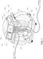
- an example PD system 100 includes a PD cycler (also referred to as a PD machine) 102 seated on a cart 104.
- the PD cycler 102 includes a housing 106, a door 108, and a cassette interface 110 that abuts a disposable PD cassette 112 when the cassette 112 is disposed within a cassette compartment 114 formed between the cassette interface 110 and the closed door 108.
- a heater tray 116 is positioned on top of the housing 106.
- the heater tray 116 is sized and shaped to accommodate a bag of dialysis solution (e.g., a five liter bag of dialysis solution).
- the PD cycler 102 also includes a touch screen 118 and additional control buttons 120 that can be operated by a user (e.g., a patient) to allow, for example, set-up, initiation, and/or termination of a PD treatment.
- Dialysis solution bags 122 are suspended from fingers on the sides of the cart 104, and a heater bag 124 is positioned on the heater tray 116.
- the dialysis solution bags 122 and the heater bag 124 are connected to the cassette 112 via dialysis solution bag lines 126 and a heater bag line 128, respectively.
- the dialysis solution bag lines 126 can be used to pass dialysis solution from dialysis solution bags 122 to the cassette 112 during use
- the heater bag line 128 can be used to pass dialysis solution back and forth between the cassette 112 and the heater bag 124 during use.
- a patient line 130 and a drain line 132 are connected to the cassette 112.
- the patient line 130 can be connected to a patient's abdomen via a catheter, and can be used to pass dialysis solution back and forth between the cassette 112 and the patient during use.
- the drain line 132 can be connected to a drain or drain receptacle and can be used to pass dialysis solution from the cassette 112 to the drain or drain receptacle during use.
- the spent dialysate is also referred to as effluent herein.
- the cassette 112 generally includes a rigid plastic molded base member and a flexible membrane attached to the base. The base and the membrane of the cassette 112 cooperate to define various dialysis solution channels and dialysis solution chambers integrally within the cassette 112.
- the cassette 112 is configured to align with various valve actuators, sensors and other components of the PD cycler 102 when the cassette 112 is coupled with the PD cycler 102.
- the cassette 112 can be a single-use disposable element used for a PD treatment.
- FIG. 2 shows a more detailed view of the cassette interface 110 and the door 108 of the PD cycler 102.
- the PD cycler 102 includes pistons 133A, 133B with piston heads 134A, 134B that can be axially moved within piston access ports 136A, 136B formed in the cassette interface 110.
- the pistons 133A, 133B include shafts that are connected to motors that can be operated to move the piston heads 134A, 134B axially inward and outward within the piston access ports 136A, 136B.
- the piston heads 134A, 134B of the PD cycler 102 align with pump chambers 138A, 138B of the cassette 112 such that the piston heads 134A, 134B can be mechanically connected to fastening members of the cassette 112 overlying the pump chambers 138A, 138B.
- movement of the piston heads 134A, 134B toward the cassette 112 during treatment can decrease the volume of the pump chambers 138A, 138B, and force dialysis solution out of the pump chambers 138A, 138B, while retraction of the piston heads 134A, 134B away from the cassette 112 can increase the volume of the pump chambers 138A, 138B and cause dialysis solution to be drawn into the pump chambers 138A, 138B.
- the patient line 130 extending from the cassette 112 is connected to a patient's abdomen via a catheter, and the drain line 132 is connected to a drain or drain receptacle.
- the PD treatment typically begins by emptying the patient of spent dialysis solution that remains in the patient's abdomen from the previous treatment.
- the pump of the PD cycler 102 is activated to cause the pistons 133A, 133B to reciprocate to cause the spent dialysis solution to be drawn from the patient into the patient line 130, and then to the fluid pump chambers 138A, 138B of the cassette 112.
- the spent dialysis solution is then pumped from the fluid pump chambers 138A, 138B to the drain via the drain line 132.
- heated dialysis solution is transferred from the heater bag 124, through the cassette 112, and to the patient via the patient line 130.
- the motor or motors of the PD cycler 102 is/are activated to cause the pistons 133A, 133B to reciprocate and certain inflatable members 142 of the PD cycler 102 are inflated to cause the warmed dialysis solution to be drawn into the fluid pump chambers 138A, 138B of the cassette 112 from the heater bag 124 via the heater bag line 128.
- the warmed dialysis solution is then pumped from the fluid pump chambers 138A, 138B to the patient via the patient line 130.
- the dialysis solution is allowed to dwell within the patient for a period of time. During this dwell period, toxins cross the peritoneum of the patient into the dialysis solution from the patient's blood.
- the PD cycler 102 prepares fresh dialysate for delivery to the patient in a subsequent cycle. In particular, the PD cycler 102 pumps fresh dialysis solution from one of the four full dialysis solution bags 122 into the heater bag 124 for heating.
- the pump of the PD cycler 102 is activated to cause the pistons 133A, 133B to reciprocate and certain inflatable members 142 of the PD cycler 102 are inflated to cause the dialysis solution to be drawn into the fluid pump chambers 138A, 138B of the cassette 112 from the selected dialysis solution bag 122 via its associated line 126.
- the dialysis solution is then pumped from the fluid pump chambers 138A, 138B to the heater bag 124 via the heater bag line 128.
- the spent dialysis solution is pumped from the patient through the patient line 130, and then to the drain via drain line 132.
- the heated dialysis solution is then pumped from the heater bag 124 and through the patient line 130 to the patient where it dwells for a desired period of time.
- These steps are repeated with the dialysis solution from two of the three remaining dialysis solution bags 122.
- the dialysis solution from the last dialysis solution bag 122 is typically delivered to the patient via the patient line 130 and left in the patient until the subsequent PD treatment.
- PD treatments usually occur at night while the patient is sleeping.
- APD treatment typically involves several fills and drains of many liters of dialysate fluid, and may occur over the entire night.
- the patient line 130 (connected to the patient) may inadvertently become obstructed to fluid flow because of unintentional kinking or pinching (crushing) of the patient line 130 tubing.
- the patient may simply roll over while sleeping, causing the patient line 130 to become partially or fully kinked or crushed.
- the PD treatment can be partially or fully inhibited, disrupted, and/or discontinued.
- Most PD systems have one or more pressure sensors to monitor the fluid pressure in the patient line 130. Those pressure sensors can detect when the patient line 130 has become obstructed because of being partially or fully kinked or crushed. In such a case, the PD system (e.g., the PD cycler 102) may pause the treatment and deliver an alert/alarm in attempt to wake the patient. An awakened patient will then need to check for kinks and/or compression of the patient line 130, resolve the problem, and then resume treatment. Unfortunately for the patient, this scenario may repeat itself many times during a night.
- the PD system e.g., the PD cycler 102
- One potential way to mitigate the problem of the patient line 130 becoming obstructed because of kinking or crushing is to make the patient line 130 stiff so that it is very resistant to bending and compression.
- metal wires are embedded in the wall of tubing for such purposes.
- the tubing used for the patient line 130 is made very stiff (resistant to bending and compression), then the tubing tends to be very uncomfortable for the patient to use. For example, when the patient rolls over during sleep, the stiff tube used for the patient line 130 will likely cause substantial stress and pain to the patient via lateral forces exerted by the catheter to the patient.
- making the patient line 130 flexible while also tolerant to kinking and crushing will provide a more effective PD treatment (e.g., with less interruptions), and a better patient experience (e.g., with fewer alarms and fewer required interventions). That is, tubing that is flexible and that will allow for flow through the tubing even while kinked or crushed will provide many benefits when used as the patient line 130 for the PD system 100 (and for other medical uses).
- FIGS. 3 and 4 a portion of an example kink and compression tolerant medical tubing 300 (or simply “tubing 300") is illustrated.
- FIG. 4 shows a cross-sectional shape of the tubing 300.
- the kink and compression tolerant medical tubing 300 can be advantageously used as the patient line 130 ( FIGS. 1 and 2 ), for example.
- the tubing 300 can be made from any suitable polymeric material, such as polyvinyl chloride (PVC).
- PVC polyvinyl chloride
- the PVC material has a durometer of shore 70.
- the durometer of the PVC material is in a range of shore 65 to shore 75, or shore 60 to shore 80, or shore 55 to shore 85.
- the tubing 300 is preferably sufficiently flexible and compliant so that movements of the patient that result in bending of the tubing 300 do not induce stress at the location where the tubing 300 is percutaneously attached to the patient (e.g., via a catheter). In the depicted embodiment, there is no reinforcing wire/material within the wall of the tubing 300.
- the tubing 300 is scalable to any suitable size.
- the outer diameter of the tubing 300 is 6.0 mm and the inner diameter of the tubing 300 is 4.0 mm (hence, the inner radius 320 is 2.0 mm).
- the tubing 300 can be made to have any suitable length.
- the tubing 300 defines a single lumen 302 through which fluid can flow.
- the lumen 302 is the open space within the tubing 300.
- the tubing 300 includes three internal ribs 3 10a, 310b, and 310c (or collectively "ribs 3 10a-c").
- the ribs 310a-c are triangular projections that extend inward from the inner wall of the tubing.
- Each of the triangular ribs 3 10a-c includes an apex, and the ribs 310a-c are arranged such that the apices are pointed towards a geometric center 301 of the tubing 300.
- the triangular ribs 3 10a-c are arranged at about 120 degrees relative to each other around the 360 degree inner circumference of the tubing 300.
- a central longitudinal axis of the tubing 300 extends along the geometric center 301.
- the ribs 3 10a-c and the wall of the tubing 300 are contiguous and made of the same material (e.g., by extrusion).
- the lumen 302 is the open space within the tubing 300 (and does not include the area of the ribs 3 10a-c).
- Each of the ribs 3 10a-c extends inward from the inner wall of the tubing 300 for a distance that is referred to as the rib height 330.
- the rib height 330 is less than the inner radius 320. As described further below, the inventors have discovered that when the rib height 330 is 43% of the inner radius 320, the size of the lumen 302 is maximized while the tubing 300 is fully compressed.
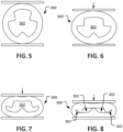
- FIGS. 5-8 depicts the tubing 300 in four differing states of lateral compression. This type of compression to the tubing 300 may be induced, for example, by kinking (bending), by pure lateral compression (crushing), or by a combination of both.
- FIG 5 the tubing 300 is not compressed or deformed.
- FIG. 8 the tubing 300 is considered to be fully compressed (e.g., the apex of each of the three ribs 310a-c is in contact with the inner wall of the tubing 300).
- FIGS. 6 and 7 depict successive degrees of compression between FIGS. 5 and 8 .
- the cross-section of the lumen 302 is shaped differently in each of the depicted differing states of compression.
- the lumen 302 is divided up into multiple separated portions while the tubing 300 is in the fully compressed state (shown in FIG 8 ).
- the lumen 302 is divided up into four separated open area portions while the tubing 300 is in the fully compressed state.
- the tubing 300 is kink and compression tolerant because, as FIG 8 illustrates, even though the tubing 300 is fully compressed there is/are still open area(s) (the lumen 302) that allows fluid to flow through the tubing 300.
- the inventors have discovered that when the rib height 330 is 43% of the inner radius 320, the open area of the lumen 302 is maximized while the tubing 300 is fully compressed.
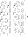
- tubing 400a, 400b, 400c, 400d, 400e, 400f, 400g, 400h, 400i, and 400j are each illustrated in uncompressed and fully compressed states.
- the tubing 400a-j differ from each other with respect to an individual tubing's rib height as a percentage of its inner radius.
- tubing 400a has no ribs; the height of the ribs of the tubing 400b are each 6% of the inner radius of tubing 400b; the height of the ribs of the tubing 400c are each 13% of the inner radius of tubing 400c; the height of the ribs of the tubing 400d are each 21% of the inner radius of tubing 400d; the height of the ribs of the tubing 400e are each 32% of the inner radius of tubing 400e; the height of the ribs of the tubing 400f are each 43% of the inner radius of tubing 400f; the height of the ribs of the tubing 400g are each 52% of the inner radius of tubing 400g; the height of the ribs of the tubing 400h are each 60% of the inner radius of tubing 400h; the height of the ribs of the tubing 400i are each 70% of the inner radius of tubing 400i; and the height of the ribs of the tubing 400j are each 79% of the inner radius of tubing 400j.
- the inventors created a solid model of each design of the tubing 400a-j. Then, using finite element analysis (FEA), the fully compressed state for each design of the tubing 400a-j was simulated (as shown). From there, the fully compressed open area of each design of the tubing 400a-j was calculated.
- FEA finite element analysis
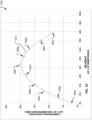
- the results of the calculations of the fully compressed open areas of each design of the tubing 400a-j are shown in a graph 500. That is, the graph 500 is a plot of the fully compressed open area of each design of the tubing 400a-j as a function of each tubing's rib height as a percentage of its inner radius. The individual open area value for each design of the tubing 400a-j is shown, and a fit line 510 is also shown.
- the graph 500 shows that the tubing 400f yields the greatest amount of open area when fully compressed.
- the ribs of the tubing 400f are each 43% of the inner radius of tubing 400f.
- the open area of the tubing 400f while it is in the fully compressed state is about 20% of the uncompressed open area of the tubing 400f.
- the fit line 510 shows that the open area while fully compressed is effectively optimal in a range of about 40% to about 46% in terms of rib height as a percentage of inner radius.
- the inventors also experimented with the kink and compression tolerance effects of various numbers of ribs in the tubing. For example, the inventors experimented with zero ribs, two ribs, three ribs, four ribs, five ribs, six ribs, and seven ribs. The results of such experiments demonstrated that the three rib design was superior than the others.
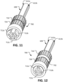
- tubing 600 is internally the same as the tubing 300 and tubing 400f described above.
- FIG 11 the internally ribbed tubing 600 is illustrated as fully open, and in FIG 12 the internally ribbed tubing 600 is illustrated as fully closed because the tube closure device 700 is acting on the tubing 600.
- the collet-like tube closure device 700 includes an externally threaded sleeve 710 and an internally threaded clamp collar 720.
- the externally threaded sleeve 710 and the internally threaded clamp collar 720 are threadedly coupled together. Accordingly, when the internally threaded clamp collar 720 is rotated in relation to the externally threaded sleeve 710 the internally threaded clamp collar 720 will move longitudinally in relation to the externally threaded sleeve 710. For example, while in FIG 11 the externally threaded sleeve 710 and the internally threaded clamp collar 720 are essentially abutting against each other, in FIG. 12 there is a gap 702 between the externally threaded sleeve 710 and the internally threaded clamp collar 720.
- the externally threaded sleeve 710 defines an opening that slidingly receives the tubing 600.
- Three jaws 712a, 712b, and 712c are connected to and extend longitudinally from the externally threaded sleeve 710 like cantilevered beams.
- the jaws 712a, 712b, and 712c are radially deflectable in relation to the externally threaded sleeve 710.
- Each of the three jaws 712a, 712b, and 712c includes a respective ramp surface 714a, 714b, and 714c.
- the internally threaded clamp collar 720 includes a corresponding annular ramp surface 722 that slidingly mates against the ramp surfaces 714a, 714b, and 714c.
- the internally threaded clamp collar 720 can be threadedly adjusted in relation to the externally threaded sleeve 710 such that the ramp surface 722 adjustably exerts pressure on each of the three jaws 712a, 712b, and 712c to force the jaws 712a, 712b, and 712c radially inward. For example, in FIG.
- the three jaws 712a, 712b, and 712c are depicted as being forced radially inward by the internally threaded clamp collar 720, whereas in FIG 11 the three jaws 712a, 712b, and 712c are depicted as radially positioned such that the tubing 600 is uncompressed (because the internally threaded clamp collar 720 is not pressing the three jaws 712a, 712b, and 712c radially inward).
- the tubing 600 defines three longitudinally-extending grooves 612a, 612b, and 612c extending along the outer surface of the tubing 600.
- the three longitudinally-extending grooves 612a, 612b, and 612c are in radial alignment with the three internal ribs of the tubing 600 (see e.g., the example internal ribs 310a, 310b, and 310c of tubing 300 as shown in FIG 4 ).
- the three jaws 712a, 712b, and 712c are matingly positioned within the three longitudinally-extending grooves 612a, 612b, and 612c. That is, the jaw 712a is positioned within the groove 612a, the jaw 712b is positioned within the groove 612b, and the jaw 712c is positioned within the groove 612c.
- the externally threaded sleeve 710 is slid longitudinally along the tubing 600, the three jaws 712a, 712b, and 712c slide within the three longitudinally-extending grooves 612a, 612b, and 612c.
- the three longitudinally-extending grooves 612a, 612b, and 612c are in radial alignment with the three internal ribs of the tubing 600, and because the three jaws 712a, 712b, and 712c are positioned within the three longitudinally-extending grooves 612a, 612b, and 612c, it follows that the three jaws 712a, 712b, and 712c are in radially alignment with the three internal ribs of the tubing 600. Accordingly, when the three jaws 712a, 712b, and 712c are forced radially inward by the internally threaded clamp collar 720, the three internal ribs of the tubing 600 are forced toward the center of the tubing 600. The apices of the three internal ribs of the tubing 600 meet each other at the center of the tubing 600. As a result the tubing 600 becomes fully closed (there is no open portion of the lumen of the tubing 600).
- the internally threaded clamp collar 720 is positioned in relation to the three jaws 712a, 712b, and 712c such that the ramp surface 722 of the internally threaded clamp collar 720 is not exerting sufficient pressure on the ramp surfaces 714a, 714b, and 714c of the three jaws 712a, 712b, and 712c to cause the jaws 712a, 712b, and 712c to compress the tubing 600. Then, in order to begin to close the tubing 600, a user can twist the internally threaded clamp collar 720 in relation to the externally threaded sleeve 710.
- the internally threaded clamp collar 720 will move longitudinally away from the externally threaded sleeve 710 and the ramp surface 722 of the internally threaded clamp collar 720 will begin to exert pressure on the ramp surfaces 714a, 714b, and 714c of the three jaws 712a, 712b, and 712c to cause the jaws 712a, 712b, and 712c to compress the tubing 600.
- the user can continue twisting the internally threaded clamp collar 720 in relation to the externally threaded sleeve 710 until the ramp surface 722 of the internally threaded clamp collar 720 exerts sufficient pressure on the ramp surfaces 714a, 714b, and 714c of the three jaws 712a, 712b, and 712c to cause the jaws 712a, 712b, and 712c to fully close the tubing 600 by causing the three internal ribs of the tubing 600 meet each other at the center of the tubing 600 (as depicted in FIG. 12 ).
- FIG. 15 illustrates another example kink and compression tolerant medical tubing 800.
- the tubing 800 includes three ribs 810a, 810b, and 810c.
- the ribs 810a-c can be triangular and can have, for example, a rib height that is 43% of the inner radius of the tubing 800.
- the ribs 310a, 310b, and 310c of the tubing 300 extend parallel to the longitudinal axis of the tubing 300
- the ribs 810a, 810b, and 810c spiral around the longitudinal axis of the tubing 800.
- the ribs 810a, 810b, and 810c extend helically around the longitudinal axis of the tubing 800.
- the angle that the ribs 810a, 810b, and 810c extend in relation to the longitudinal axis of the tubing 800 can be in a range between 5 degrees to 15 degrees, or between 10 degrees to 20 degrees, or between 15 degrees to 25 degrees, or between 20 degrees to 30 degrees, or between 25 degrees to 35 degrees, or between 30 degrees to 40 degrees, or between 35 degrees to 45 degrees, or more than 45 degrees.
- This tubing design with spirally extending internal ribs 810a, 810b, and 810c can advantageously provide consistent bending/flexure properties regardless of the bend direction relative to the tubing 800.
- tubing 300 has been described as being made from PVC, in some embodiments, the tubing 300 can be made from any other suitable polymeric material such as, but not limited to, polyethylene, polyurethanes, nylons, fluoropolymers, natural rubber, natural rubber latex, synthetic rubber, thermoplastic rubbers, silicone, and the like, and combinations thereof.
- the tubing 300 has been described as having an outer diameter of 6.0 mm, in some embodiments, the tubing 300 has an outer diameter in a range of 1.0 mm to 5.0 mm, or 3.0 mm to 7.0 mm, 5.0 mm to 9.0 mm, or 7.0 mm to 1.1 cm, or 9.0 mm to 1.3 cm, or 1.1 cm to 1.5 cm, or 1.3 cm to 1.7 cm, or 1.5 cm to 1.9 cm, or 1.7 cm to 2.1 cm, and/or more than 2.1 cm.
- the tubing 300 has an inner diameter in a range of 1.0 mm to 5.0 mm, or 3.0 mm to 7.0 mm, 5.0 mm to 9.0 mm, or 7.0 mm to 1.1 cm, or 9.0 mm to 1.3 cm, or 1.1 cm to 1.5 cm, or 1.3 cm to 1.7 cm, or 1.5 cm to 1.9 cm, or 1.7 cm to 2.1 cm, and/or more than 2.1 cm.
- tubing 300 there is no reinforcing wire/material within the wall of the tubing 300, in some embodiments, one or more wires or other types of reinforcing materials can be included within the wall of the tubing 300.
- tubing 300 includes three internal ribs 310a-c, in some embodiments, one, two, four, five, six, seven, or more than seven ribs are included.
- the rib height 330 is 43% of the radius 320 of the tubing 300
- the rib height 330 is in a range of 42% to 44%, or 40% to 46%, or 38% to 48%, or 36% to 50%, or 34% to 38%, or 36% to 40%, or 38% to 42%, or 40% to 44%, or 42% to 46%, or 44% to 48%, or 46% to 50%, or 48% to 52%, or 50% to 54% of the radius 320 of the tubing 300.
- ribs 310a-c have been described as triangular shaped, in some embodiments, other shapes as used such as, but not limited to, rectangular, ovular, and so on. While in the depicted embodiment the ribs 3 10a-c are solid, in some embodiments, the ribs 310a-c are hollow (have open space within the boundaries of the ribs 310a-c).
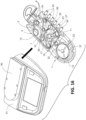
- FIG. 16 illustrates a PD system 500 including a cycler 51 and a cartridge 2 (e.g., a liquid distribution system) that, when connected to the cycler 51, forms a peristaltic pump.
- a cartridge 2 e.g., a liquid distribution system
- the cartridge 2 includes a pumping element 1, a first hub chamber 7, and a second hub chamber 8.
- the first chamber 7 includes a pump inlet 26 that can be connected to the pumping element 1 via a pump enter line, a liquid supply port 9 with a valve that can be connected to a liquid supply container via a liquid supply line, and a patient port 10 with a valve that can be connected to a patient via a patient line 5.
- the patient line 5 can be kink and compression tolerant tubing (e.g., like the tubing 300 described above in reference to FIGS. 3-8 , and/or like the tubing 600 described above in reference to FIGS. 11-14 , and/or like the tubing 800 described above in reference to FIG 15 ).
- the second hub chamber 8 includes a pump outlet 27 that can be connected to the pumping element 1 via a pump exit line, a drain port 11 with a valve that can be connected to a drain collector via a drain line along which a chemical testing device 200 positioned (e.g. as shown in FIG 17 ), and a patient port 16 with a valve that can be connected to a patient 4 via the patient line 5.
- the cartridge 2 further forms a cavity 15, which forms part of a pressure sensor.
- the first hub chamber 7 has three liquid supply ports 9, one patient port 10, one pump inlet 26, and a cavity 36 that forms part of a pressure sensor.
- the second hub chamber 8 has a patient port 18, a drain port 11, and a pump outlet 27.
- the cartridge 2 also includes a warmer chamber 17, which includes a warmer port 19 and a patient port 16.
- the warmer port 19 is connected to a warmer 28 (shown in FIG 17 ) via a warmer tube connector 55 and a warmer exit line 30.
- the patient port 16 is connected to the patient line 5.
- the second hub chamber 8 includes a warmer port 38 connected to a warmer 28 via a warmer tube connector 23 and a warmer enter line 29.
- the pumping element 1 includes a pump casing 45, which contains three rollers 22 maintained around a center of the pump casing 45 by a roller separator 12.
- the space between the roller separator 12 and the pump casing 45 defines a pump race 21 in which a flexible tube 37 is disposed.
- the flexible tube 37 is connected to the pump enter line 56 and the pump exit 57 line.
- the rollers 22 may be motor driven by a shaft 52 (shown in FIG 18 ) in such a way as to progressively compress the flexible tube 37, thereby resulting in a peristaltic movement of fluid contained within and along the flexible tube 37. Accordingly, the pump casing 45, the rollers 22, the roller separator 12, and the pump race 21 together form a peristaltic pump by which liquid (e.g., dialysate) can be moved through the PD system 500.
- liquid e.g., dialysate
- FIG. 17 shows an assembly including the cartridge 2, a patient line 5, supply bags 3, a warmer enter line 29, a warmer outer line 30, a warmer pouch 28 to be put into contact with a warming plate, a drain line 25, and the chemical testing device 25 installed to the drain line 25.
- the patient line 5 can be kink and compression tolerant tubing (such as the tubing 300 described above in reference to FIGS. 3-8 , the tubing 600 described above in reference to FIGS. 11-14 , or the tubing 800 described above in reference to FIG 15 ).
- FIG. 18 shows the cycler 51 with the slot 50 and the cartridge 2 omitted to illustrate various internal features of the cycler 51.
- the cycler 51 includes a driving zone, which includes a several actuators 34 and a motor shaft 52 for interfacing with the rollers 22.
- the cycler 51 also includes an air sensor 43 situated close to the patient line 5 when the cartridge 2 is inserted.
- FIG. 19 shows the cycler 51 with the insertion slot 50 in an open configuration and with the cartridge 2 disposed within the insertion slot 50
- FIG 20 shows the cycler 51 with the insertion slot 50 in a closed configuration and with the cartridge 2 disposed within the insertion slot 50.
Landscapes
- Health & Medical Sciences (AREA)
- Heart & Thoracic Surgery (AREA)
- Engineering & Computer Science (AREA)
- Urology & Nephrology (AREA)
- Life Sciences & Earth Sciences (AREA)
- Public Health (AREA)
- Veterinary Medicine (AREA)
- Biomedical Technology (AREA)
- Hematology (AREA)
- Anesthesiology (AREA)
- Animal Behavior & Ethology (AREA)
- General Health & Medical Sciences (AREA)
- Emergency Medicine (AREA)
- Vascular Medicine (AREA)
- General Engineering & Computer Science (AREA)
- Pulmonology (AREA)
- Mechanical Engineering (AREA)
- Biophysics (AREA)
- External Artificial Organs (AREA)
Claims (15)
- Système de tube médical comprenant :une cassette de fluide médical (112) comprenant un élément de base,une membrane flexible fixée à l'élément de base de sorte que la membrane et l'élément de base coopèrent pour définir une ou plusieurs voies d'écoulement de fluide à l'intérieur de la cassette de fluide médical, etun tube (300, 400, 600, 800, 5) s'étendant à partir de la cassette de fluide médical et en communication fluidique avec la ou les voies d'écoulement de fluide, le tube définissant un axe longitudinal central à un centre géométrique (301) d'une section transversale du tube, caractérisé en ce que le tube comprend des nervures internes (310, 810) s'étendant vers l'intérieur à partir d'une paroi interne du tube vers l'axe longitudinal central au centre géométrique (301) de la section transversale du tube ; etun dispositif de fermeture du tube (700) comprenant un manchon (710) définissant une ouverture qui reçoit le tube par glissement,un ensemble de mâchoires (712) couplées au manchon et pouvant être déviées radialement par rapport au manchon, etun collier de serrage (720) positionné autour d'au moins des parties d'ensemble de mâchoires et mobile longitudinalement par rapport à l'ensemble de mâchoires.
- Système de tube médical selon la revendication 1, les nervures internes ayant des formes de section transversale triangulaires, et des sommets des formes de section transversale triangulaires pointant vers l'axe longitudinal central au centre géométrique de la section transversale du tube.
- Système de tube médical selon la revendication 2, le collier de serrage étant mobile longitudinalement par rapport à l'ensemble de mâchoires entre : i) une première position dans laquelle l'ensemble de mâchoires est dans une configuration ouverte et ii) une deuxième position dans laquelle le collier de serrage dévie l'ensemble de mâchoires radialement vers l'intérieur par rapport à la configuration ouverte de sorte que des sommets des nervures internes se rejoignent au centre du tube.
- Système de tube médical selon l'une quelconque des revendications 1 à 3, le tube comprenant trois des nervures internes.
- Système de tube médical selon l'une quelconque des revendications 1 à 4, les nervures internes ayant des hauteurs comprises entre 40 et 46 pour cent d'un rayon intérieur du tube.
- Système de tube médical selon l'une quelconque des revendications 1 à 5, la cassette de fluide médical étant une cassette de fluide de dialyse péritonéale, et éventuellement le tube étant une ligne de patient.
- Système de tube médical selon l'une quelconque des revendications 1 à 6, le tube ayant un duromètre de shore 70.
- Système de tube médical selon n'importe quelle revendication précédente, le collier de serrage étant mobile longitudinalement par rapport à l'ensemble de mâchoires entre : i) une première position dans laquelle l'ensemble de mâchoires est dans une configuration ouverte et ii) une deuxième position dans laquelle le collier de serrage dévie l'ensemble de mâchoires radialement vers l'intérieur par rapport à la configuration ouverte.
- Système de tube médical selon n'importe quelle revendication précédente, chaque mâchoire de l'ensemble de mâchoires comprenant une surface de rampe (714) qui s'accouple de manière coulissante à une surface de rampe annulaire correspondante du collier de serrage.
- Système de tube médical selon n'importe quelle revendication précédente, le collier de serrage étant accouplé par filetage sur le manchon, par exemple, le collier de serrage comprenant un filetage interne qui s'accouple par filetage avec un filetage externe du manchon.
- Système de tube médical selon n'importe quelle revendication précédente, lorsque le dispositif de fermeture de tube est positionné sur le tube, chaque mâchoire de l'ensemble de mâchoires pouvant être alignée radialement avec une nervure interne respective du tube.
- Système de tube médical selon n'importe quelle revendication précédente, le tube comprenant trois nervures internes, et l'ensemble de mâchoires comprenant trois mâchoires.
- Système de tube médical selon n'importe quelle revendication précédente, le tube définissant des rainures longitudinales (612) s'étendant le long d'une surface extérieure du tube qui sont alignées radialement avec les nervures internes.
- Système de tube médical selon n'importe quelle revendication précédente, le tube étant un tube médical tolérant au pliage et à la compression qui a un duromètre dans une plage de shore 65 à shore 75.
- Système de tube médical selon la revendication 14, les nervures internes s'enroulant en spirale autour de l'axe longitudinal central.
Applications Claiming Priority (2)
| Application Number | Priority Date | Filing Date | Title |
|---|---|---|---|
| US15/978,414 US10918828B2 (en) | 2018-05-14 | 2018-05-14 | Kink and compression tolerant medical tubing |
| PCT/US2019/027840 WO2019221870A1 (fr) | 2018-05-14 | 2019-04-17 | Tube médical tolérant au pliage et à la compression |
Publications (2)
| Publication Number | Publication Date |
|---|---|
| EP3762061A1 EP3762061A1 (fr) | 2021-01-13 |
| EP3762061B1 true EP3762061B1 (fr) | 2025-01-15 |
Family
ID=66429582
Family Applications (1)
| Application Number | Title | Priority Date | Filing Date |
|---|---|---|---|
| EP19722357.1A Active EP3762061B1 (fr) | 2018-05-14 | 2019-04-17 | Tube médical tolérant au pliage et à la compression |
Country Status (6)
| Country | Link |
|---|---|
| US (1) | US10918828B2 (fr) |
| EP (1) | EP3762061B1 (fr) |
| CN (1) | CN112118877B (fr) |
| CA (1) | CA3097974A1 (fr) |
| MX (1) | MX2020012154A (fr) |
| WO (1) | WO2019221870A1 (fr) |
Families Citing this family (4)
| Publication number | Priority date | Publication date | Assignee | Title |
|---|---|---|---|---|
| CN113144320B (zh) * | 2021-05-21 | 2024-07-12 | 端源医疗科技无锡有限公司 | 一种自动止流血液透析留置针及使用方法 |
| GB2612618A (en) * | 2021-11-05 | 2023-05-10 | Salts Healthcare Ltd | A connector for connecting to an ostomy appliance |
| CN114949389A (zh) * | 2022-05-23 | 2022-08-30 | 饶旺 | 儿科术后负压引流装置 |
| JP7751889B2 (ja) * | 2023-05-22 | 2025-10-09 | 株式会社トヨックス | 可撓管 |
Citations (4)
| Publication number | Priority date | Publication date | Assignee | Title |
|---|---|---|---|---|
| US1596754A (en) * | 1923-10-30 | 1926-08-17 | Judson D Moschelle | Reenforced tubing |
| US3720235A (en) * | 1970-09-30 | 1973-03-13 | Moore & Co Samuel | Composite tubing |
| US4811928A (en) * | 1985-12-04 | 1989-03-14 | Pfrimmer-Viggo Gmbh & Co. Kg | Control clamp for infusion hoses |
| EP2762182A1 (fr) * | 2011-09-26 | 2014-08-06 | Terumo Kabushiki Kaisha | Dispositif de protection et son procédé d'utilisation |
Family Cites Families (24)
| Publication number | Priority date | Publication date | Assignee | Title |
|---|---|---|---|---|
| FR711568A (fr) | 1930-03-03 | 1931-09-12 | Gas Light & Coke Co | Perfectionnements aux tubes flexibles, tels que les tubes en caoutchouc et matière analogue |
| US3957054A (en) | 1973-09-26 | 1976-05-18 | Mcfarlane Richard H | Surgical drainage tube |
| FR2317526A1 (fr) | 1975-07-08 | 1977-02-04 | Rhone Poulenc Ind | Pompe peristaltique |
| US4257422A (en) | 1979-03-14 | 1981-03-24 | Minnesota Mining And Manufacturing Company | Surgical drain |
| US4398910A (en) * | 1981-02-26 | 1983-08-16 | Blake L W | Wound drain catheter |
| US4579555A (en) | 1983-12-05 | 1986-04-01 | Sil-Fab Corporation | Surgical gravity drain having aligned longitudinally extending capillary drainage channels |
| US4681570A (en) | 1985-12-26 | 1987-07-21 | Dalton Michael J | Peritoneal catheter |
| US4923223A (en) | 1988-08-05 | 1990-05-08 | Plastic Specialties And Technologies Investments, Inc. | Kink impeding hose for spraying water |
| US4867485A (en) | 1988-08-05 | 1989-09-19 | Colorite Plastics Co. | Kink impeding hose and coupling |
| US5215450A (en) | 1991-03-14 | 1993-06-01 | Yehuda Tamari | Innovative pumping system for peristaltic pumps |
| US7163524B2 (en) * | 2002-02-27 | 2007-01-16 | Terumo Kabushiki Kaisha | Catheter |
| DE10224750A1 (de) * | 2002-06-04 | 2003-12-24 | Fresenius Medical Care De Gmbh | Vorrichtung zur Behandlung einer medizinischen Flüssigkeit |
| AUPS280102A0 (en) * | 2002-06-07 | 2002-06-27 | Barrett, Graham David | Aspiration tubing |
| US8684967B2 (en) | 2003-07-15 | 2014-04-01 | Medtronic, Inc. | Kink resistant cannula having buckle resistant apertures |
| US7918247B2 (en) | 2004-10-20 | 2011-04-05 | Ames True Temper, Inc. | Garden hose with backbone |
| WO2007141463A1 (fr) | 2006-06-05 | 2007-12-13 | Ecoluminaire Limited | Conduit de transport de fluide |
| US7981074B2 (en) | 2006-11-02 | 2011-07-19 | Novartis Ag | Irrigation/aspiration system |
| DE102007055675A1 (de) | 2007-11-21 | 2009-05-28 | Iprm Intellectual Property Rights Management Ag | Medizinischer Schlauch |
| EP3498316B1 (fr) * | 2011-11-04 | 2020-07-22 | DEKA Products Limited Partnership | Système de traitement médical et procédés faisant appel à une pluralité de conduites de fluide |
| US9744332B2 (en) | 2012-01-18 | 2017-08-29 | Contech Medical, Inc. | Lubricious extruded medical tubing |
| US9561323B2 (en) | 2013-03-14 | 2017-02-07 | Fresenius Medical Care Holdings, Inc. | Medical fluid cassette leak detection methods and devices |
| US9878125B2 (en) * | 2013-06-20 | 2018-01-30 | Zcath Llc | Intermittent urinary catheter |
| DE102014106490A1 (de) * | 2014-05-08 | 2015-11-12 | B. Braun Avitum Ag | Schlauchleitung für frische und/oder verbrauchte Dialysierflüssigkeit |
| US20160030708A1 (en) * | 2014-07-30 | 2016-02-04 | Angiodynamics, Inc. | Rifled catheters and vascular access systems |
-
2018
- 2018-05-14 US US15/978,414 patent/US10918828B2/en active Active
-
2019
- 2019-04-17 CA CA3097974A patent/CA3097974A1/fr active Pending
- 2019-04-17 EP EP19722357.1A patent/EP3762061B1/fr active Active
- 2019-04-17 CN CN201980032269.9A patent/CN112118877B/zh active Active
- 2019-04-17 WO PCT/US2019/027840 patent/WO2019221870A1/fr not_active Ceased
- 2019-04-17 MX MX2020012154A patent/MX2020012154A/es unknown
Patent Citations (4)
| Publication number | Priority date | Publication date | Assignee | Title |
|---|---|---|---|---|
| US1596754A (en) * | 1923-10-30 | 1926-08-17 | Judson D Moschelle | Reenforced tubing |
| US3720235A (en) * | 1970-09-30 | 1973-03-13 | Moore & Co Samuel | Composite tubing |
| US4811928A (en) * | 1985-12-04 | 1989-03-14 | Pfrimmer-Viggo Gmbh & Co. Kg | Control clamp for infusion hoses |
| EP2762182A1 (fr) * | 2011-09-26 | 2014-08-06 | Terumo Kabushiki Kaisha | Dispositif de protection et son procédé d'utilisation |
Also Published As
| Publication number | Publication date |
|---|---|
| CN112118877B (zh) | 2024-07-26 |
| CA3097974A1 (fr) | 2019-11-21 |
| EP3762061A1 (fr) | 2021-01-13 |
| CN112118877A (zh) | 2020-12-22 |
| US10918828B2 (en) | 2021-02-16 |
| WO2019221870A1 (fr) | 2019-11-21 |
| MX2020012154A (es) | 2021-01-29 |
| US20190344045A1 (en) | 2019-11-14 |
Similar Documents
| Publication | Publication Date | Title |
|---|---|---|
| EP3762061B1 (fr) | Tube médical tolérant au pliage et à la compression | |
| AU2014234425B2 (en) | Tube for extra-corporeal circuit with double connector | |
| JP4746016B2 (ja) | 体外流体処理時における体液の流れを制御する装置 | |
| KR100813371B1 (ko) | 커플링 기구 및 이 기구를 포함한 의료용 라인 세트 | |
| US20140271273A1 (en) | Handheld ocular aspiration tool | |
| EP3492122A1 (fr) | Insert tubulaire pour circuit extracorporel | |
| EP3824919B1 (fr) | Machine de thérapie par fluide médical comprenant une boîte de pompe pneumatique et accumulateurs associés | |
| EP3986498B1 (fr) | Contrôle et détection d'occlusion dans une voie de patient pour une machine de dialyse utilisant des paramètres de fonctionnement de pompe ajustés | |
| CN121102697A (zh) | 自动胸膜腹膜泵 | |
| CN108785777A (zh) | 一种防止移位的腹膜透析导管 | |
| US20170246370A1 (en) | Hemodialysis Device | |
| CN118338924A (zh) | 具有患者管线过滤器的腹膜透析系统 | |
| CA3138944C (fr) | Controle et detection d'occlusion dans une voie de patient pour une machine de dialyse utilisant des parametres de fonctionnement de pompe ajustes | |
| KR20240118163A (ko) | 환자 라인 필터를 갖는 복막 투석 시스템 | |
| HK1216865B (en) | Tube for extra-corporeal circuit with double connector |
Legal Events
| Date | Code | Title | Description |
|---|---|---|---|
| STAA | Information on the status of an ep patent application or granted ep patent |
Free format text: STATUS: UNKNOWN |
|
| STAA | Information on the status of an ep patent application or granted ep patent |
Free format text: STATUS: THE INTERNATIONAL PUBLICATION HAS BEEN MADE |
|
| PUAI | Public reference made under article 153(3) epc to a published international application that has entered the european phase |
Free format text: ORIGINAL CODE: 0009012 |
|
| STAA | Information on the status of an ep patent application or granted ep patent |
Free format text: STATUS: REQUEST FOR EXAMINATION WAS MADE |
|
| 17P | Request for examination filed |
Effective date: 20201008 |
|
| AK | Designated contracting states |
Kind code of ref document: A1 Designated state(s): AL AT BE BG CH CY CZ DE DK EE ES FI FR GB GR HR HU IE IS IT LI LT LU LV MC MK MT NL NO PL PT RO RS SE SI SK SM TR |
|
| AX | Request for extension of the european patent |
Extension state: BA ME |
|
| DAV | Request for validation of the european patent (deleted) | ||
| DAX | Request for extension of the european patent (deleted) | ||
| STAA | Information on the status of an ep patent application or granted ep patent |
Free format text: STATUS: EXAMINATION IS IN PROGRESS |
|
| 17Q | First examination report despatched |
Effective date: 20230828 |
|
| GRAP | Despatch of communication of intention to grant a patent |
Free format text: ORIGINAL CODE: EPIDOSNIGR1 |
|
| STAA | Information on the status of an ep patent application or granted ep patent |
Free format text: STATUS: GRANT OF PATENT IS INTENDED |
|
| RIC1 | Information provided on ipc code assigned before grant |
Ipc: F16L 55/10 20060101ALI20240813BHEP Ipc: F16L 11/12 20060101ALI20240813BHEP Ipc: A61M 39/28 20060101ALI20240813BHEP Ipc: A61M 39/08 20060101ALI20240813BHEP Ipc: A61M 1/28 20060101ALI20240813BHEP Ipc: A61M 1/16 20060101AFI20240813BHEP |
|
| INTG | Intention to grant announced |
Effective date: 20240821 |
|
| GRAS | Grant fee paid |
Free format text: ORIGINAL CODE: EPIDOSNIGR3 |
|
| GRAA | (expected) grant |
Free format text: ORIGINAL CODE: 0009210 |
|
| STAA | Information on the status of an ep patent application or granted ep patent |
Free format text: STATUS: THE PATENT HAS BEEN GRANTED |
|
| AK | Designated contracting states |
Kind code of ref document: B1 Designated state(s): AL AT BE BG CH CY CZ DE DK EE ES FI FR GB GR HR HU IE IS IT LI LT LU LV MC MK MT NL NO PL PT RO RS SE SI SK SM TR |
|
| REG | Reference to a national code |
Ref country code: CH Ref legal event code: EP Ref country code: GB Ref legal event code: FG4D |
|
| P01 | Opt-out of the competence of the unified patent court (upc) registered |
Free format text: CASE NUMBER: APP_67050/2024 Effective date: 20241218 |
|
| REG | Reference to a national code |
Ref country code: DE Ref legal event code: R096 Ref document number: 602019064851 Country of ref document: DE |
|
| REG | Reference to a national code |
Ref country code: IE Ref legal event code: FG4D |
|
| REG | Reference to a national code |
Ref country code: NL Ref legal event code: MP Effective date: 20250115 |
|
| PG25 | Lapsed in a contracting state [announced via postgrant information from national office to epo] |
Ref country code: NL Free format text: LAPSE BECAUSE OF FAILURE TO SUBMIT A TRANSLATION OF THE DESCRIPTION OR TO PAY THE FEE WITHIN THE PRESCRIBED TIME-LIMIT Effective date: 20250115 |
|
| PG25 | Lapsed in a contracting state [announced via postgrant information from national office to epo] |
Ref country code: RS Free format text: LAPSE BECAUSE OF FAILURE TO SUBMIT A TRANSLATION OF THE DESCRIPTION OR TO PAY THE FEE WITHIN THE PRESCRIBED TIME-LIMIT Effective date: 20250415 |
|
| PG25 | Lapsed in a contracting state [announced via postgrant information from national office to epo] |
Ref country code: FI Free format text: LAPSE BECAUSE OF FAILURE TO SUBMIT A TRANSLATION OF THE DESCRIPTION OR TO PAY THE FEE WITHIN THE PRESCRIBED TIME-LIMIT Effective date: 20250115 |
|
| PG25 | Lapsed in a contracting state [announced via postgrant information from national office to epo] |
Ref country code: PL Free format text: LAPSE BECAUSE OF FAILURE TO SUBMIT A TRANSLATION OF THE DESCRIPTION OR TO PAY THE FEE WITHIN THE PRESCRIBED TIME-LIMIT Effective date: 20250115 |
|
| PGFP | Annual fee paid to national office [announced via postgrant information from national office to epo] |
Ref country code: DE Payment date: 20250319 Year of fee payment: 7 |
|
| PG25 | Lapsed in a contracting state [announced via postgrant information from national office to epo] |
Ref country code: ES Free format text: LAPSE BECAUSE OF FAILURE TO SUBMIT A TRANSLATION OF THE DESCRIPTION OR TO PAY THE FEE WITHIN THE PRESCRIBED TIME-LIMIT Effective date: 20250115 |
|
| REG | Reference to a national code |
Ref country code: LT Ref legal event code: MG9D |
|
| PG25 | Lapsed in a contracting state [announced via postgrant information from national office to epo] |
Ref country code: NO Free format text: LAPSE BECAUSE OF FAILURE TO SUBMIT A TRANSLATION OF THE DESCRIPTION OR TO PAY THE FEE WITHIN THE PRESCRIBED TIME-LIMIT Effective date: 20250415 Ref country code: IS Free format text: LAPSE BECAUSE OF FAILURE TO SUBMIT A TRANSLATION OF THE DESCRIPTION OR TO PAY THE FEE WITHIN THE PRESCRIBED TIME-LIMIT Effective date: 20250515 |
|
| REG | Reference to a national code |
Ref country code: AT Ref legal event code: MK05 Ref document number: 1759434 Country of ref document: AT Kind code of ref document: T Effective date: 20250115 |
|
| PG25 | Lapsed in a contracting state [announced via postgrant information from national office to epo] |
Ref country code: HR Free format text: LAPSE BECAUSE OF FAILURE TO SUBMIT A TRANSLATION OF THE DESCRIPTION OR TO PAY THE FEE WITHIN THE PRESCRIBED TIME-LIMIT Effective date: 20250115 |
|
| PG25 | Lapsed in a contracting state [announced via postgrant information from national office to epo] |
Ref country code: PT Free format text: LAPSE BECAUSE OF FAILURE TO SUBMIT A TRANSLATION OF THE DESCRIPTION OR TO PAY THE FEE WITHIN THE PRESCRIBED TIME-LIMIT Effective date: 20250515 Ref country code: LV Free format text: LAPSE BECAUSE OF FAILURE TO SUBMIT A TRANSLATION OF THE DESCRIPTION OR TO PAY THE FEE WITHIN THE PRESCRIBED TIME-LIMIT Effective date: 20250115 |
|
| PG25 | Lapsed in a contracting state [announced via postgrant information from national office to epo] |
Ref country code: GR Free format text: LAPSE BECAUSE OF FAILURE TO SUBMIT A TRANSLATION OF THE DESCRIPTION OR TO PAY THE FEE WITHIN THE PRESCRIBED TIME-LIMIT Effective date: 20250416 Ref country code: BG Free format text: LAPSE BECAUSE OF FAILURE TO SUBMIT A TRANSLATION OF THE DESCRIPTION OR TO PAY THE FEE WITHIN THE PRESCRIBED TIME-LIMIT Effective date: 20250115 |
|
| PG25 | Lapsed in a contracting state [announced via postgrant information from national office to epo] |
Ref country code: AT Free format text: LAPSE BECAUSE OF FAILURE TO SUBMIT A TRANSLATION OF THE DESCRIPTION OR TO PAY THE FEE WITHIN THE PRESCRIBED TIME-LIMIT Effective date: 20250115 |
|
| PG25 | Lapsed in a contracting state [announced via postgrant information from national office to epo] |
Ref country code: SE Free format text: LAPSE BECAUSE OF FAILURE TO SUBMIT A TRANSLATION OF THE DESCRIPTION OR TO PAY THE FEE WITHIN THE PRESCRIBED TIME-LIMIT Effective date: 20250115 |
|
| PG25 | Lapsed in a contracting state [announced via postgrant information from national office to epo] |
Ref country code: SM Free format text: LAPSE BECAUSE OF FAILURE TO SUBMIT A TRANSLATION OF THE DESCRIPTION OR TO PAY THE FEE WITHIN THE PRESCRIBED TIME-LIMIT Effective date: 20250115 |
|
| PG25 | Lapsed in a contracting state [announced via postgrant information from national office to epo] |
Ref country code: DK Free format text: LAPSE BECAUSE OF FAILURE TO SUBMIT A TRANSLATION OF THE DESCRIPTION OR TO PAY THE FEE WITHIN THE PRESCRIBED TIME-LIMIT Effective date: 20250115 |
|
| PG25 | Lapsed in a contracting state [announced via postgrant information from national office to epo] |
Ref country code: IT Free format text: LAPSE BECAUSE OF FAILURE TO SUBMIT A TRANSLATION OF THE DESCRIPTION OR TO PAY THE FEE WITHIN THE PRESCRIBED TIME-LIMIT Effective date: 20250115 |
|
| REG | Reference to a national code |
Ref country code: DE Ref legal event code: R097 Ref document number: 602019064851 Country of ref document: DE |
|
| PG25 | Lapsed in a contracting state [announced via postgrant information from national office to epo] |
Ref country code: EE Free format text: LAPSE BECAUSE OF FAILURE TO SUBMIT A TRANSLATION OF THE DESCRIPTION OR TO PAY THE FEE WITHIN THE PRESCRIBED TIME-LIMIT Effective date: 20250115 Ref country code: CZ Free format text: LAPSE BECAUSE OF FAILURE TO SUBMIT A TRANSLATION OF THE DESCRIPTION OR TO PAY THE FEE WITHIN THE PRESCRIBED TIME-LIMIT Effective date: 20250115 |
|
| PG25 | Lapsed in a contracting state [announced via postgrant information from national office to epo] |
Ref country code: RO Free format text: LAPSE BECAUSE OF FAILURE TO SUBMIT A TRANSLATION OF THE DESCRIPTION OR TO PAY THE FEE WITHIN THE PRESCRIBED TIME-LIMIT Effective date: 20250115 |
|
| PG25 | Lapsed in a contracting state [announced via postgrant information from national office to epo] |
Ref country code: SK Free format text: LAPSE BECAUSE OF FAILURE TO SUBMIT A TRANSLATION OF THE DESCRIPTION OR TO PAY THE FEE WITHIN THE PRESCRIBED TIME-LIMIT Effective date: 20250115 |
|
| PLBE | No opposition filed within time limit |
Free format text: ORIGINAL CODE: 0009261 |
|
| STAA | Information on the status of an ep patent application or granted ep patent |
Free format text: STATUS: NO OPPOSITION FILED WITHIN TIME LIMIT |
|
| REG | Reference to a national code |
Ref country code: CH Ref legal event code: H13 Free format text: ST27 STATUS EVENT CODE: U-0-0-H10-H13 (AS PROVIDED BY THE NATIONAL OFFICE) Effective date: 20251125 |
|
| REG | Reference to a national code |
Ref country code: CH Ref legal event code: L10 Free format text: ST27 STATUS EVENT CODE: U-0-0-L10-L00 (AS PROVIDED BY THE NATIONAL OFFICE) Effective date: 20251126 |
|
| PG25 | Lapsed in a contracting state [announced via postgrant information from national office to epo] |
Ref country code: LU Free format text: LAPSE BECAUSE OF NON-PAYMENT OF DUE FEES Effective date: 20250417 |
|
| PG25 | Lapsed in a contracting state [announced via postgrant information from national office to epo] |
Ref country code: MC Free format text: LAPSE BECAUSE OF FAILURE TO SUBMIT A TRANSLATION OF THE DESCRIPTION OR TO PAY THE FEE WITHIN THE PRESCRIBED TIME-LIMIT Effective date: 20250115 |
|
| 26N | No opposition filed |
Effective date: 20251016 |
|
| REG | Reference to a national code |
Ref country code: BE Ref legal event code: MM Effective date: 20250430 |
|
| PG25 | Lapsed in a contracting state [announced via postgrant information from national office to epo] |
Ref country code: BE Free format text: LAPSE BECAUSE OF NON-PAYMENT OF DUE FEES Effective date: 20250430 |
|
| PG25 | Lapsed in a contracting state [announced via postgrant information from national office to epo] |
Ref country code: CH Free format text: LAPSE BECAUSE OF NON-PAYMENT OF DUE FEES Effective date: 20250430 |
|
| PGFP | Annual fee paid to national office [announced via postgrant information from national office to epo] |
Ref country code: GB Payment date: 20260319 Year of fee payment: 8 |
|
| PG25 | Lapsed in a contracting state [announced via postgrant information from national office to epo] |
Ref country code: IE Free format text: LAPSE BECAUSE OF NON-PAYMENT OF DUE FEES Effective date: 20250417 |
|
| PGFP | Annual fee paid to national office [announced via postgrant information from national office to epo] |
Ref country code: FR Payment date: 20260320 Year of fee payment: 8 |