EP3762156B1 - Steuerverfahren für ein hochdruckreinigungsgerät und hochdruckreinigungsgerät insbesondere zur durchführung des verfahrens - Google Patents
Steuerverfahren für ein hochdruckreinigungsgerät und hochdruckreinigungsgerät insbesondere zur durchführung des verfahrens Download PDFInfo
- Publication number
- EP3762156B1 EP3762156B1 EP18711072.1A EP18711072A EP3762156B1 EP 3762156 B1 EP3762156 B1 EP 3762156B1 EP 18711072 A EP18711072 A EP 18711072A EP 3762156 B1 EP3762156 B1 EP 3762156B1
- Authority
- EP
- European Patent Office
- Prior art keywords
- electric motor
- control device
- power consumption
- operating mode
- rotational speed
- Prior art date
- Legal status (The legal status is an assumption and is not a legal conclusion. Google has not performed a legal analysis and makes no representation as to the accuracy of the status listed.)
- Active
Links
Images

Classifications
-
- B—PERFORMING OPERATIONS; TRANSPORTING
- B08—CLEANING
- B08B—CLEANING IN GENERAL; PREVENTION OF FOULING IN GENERAL
- B08B3/00—Cleaning by methods involving the use or presence of liquid or steam
- B08B3/02—Cleaning by the force of jets or sprays
- B08B3/026—Cleaning by making use of hand-held spray guns; Fluid preparations therefor
-
- F—MECHANICAL ENGINEERING; LIGHTING; HEATING; WEAPONS; BLASTING
- F04—POSITIVE - DISPLACEMENT MACHINES FOR LIQUIDS; PUMPS FOR LIQUIDS OR ELASTIC FLUIDS
- F04B—POSITIVE-DISPLACEMENT MACHINES FOR LIQUIDS; PUMPS
- F04B17/00—Pumps characterised by combination with, or adaptation to, specific driving engines or motors
- F04B17/03—Pumps characterised by combination with, or adaptation to, specific driving engines or motors driven by electric motors
-
- F—MECHANICAL ENGINEERING; LIGHTING; HEATING; WEAPONS; BLASTING
- F04—POSITIVE - DISPLACEMENT MACHINES FOR LIQUIDS; PUMPS FOR LIQUIDS OR ELASTIC FLUIDS
- F04B—POSITIVE-DISPLACEMENT MACHINES FOR LIQUIDS; PUMPS
- F04B17/00—Pumps characterised by combination with, or adaptation to, specific driving engines or motors
- F04B17/06—Mobile combinations
-
- F—MECHANICAL ENGINEERING; LIGHTING; HEATING; WEAPONS; BLASTING
- F04—POSITIVE - DISPLACEMENT MACHINES FOR LIQUIDS; PUMPS FOR LIQUIDS OR ELASTIC FLUIDS
- F04B—POSITIVE-DISPLACEMENT MACHINES FOR LIQUIDS; PUMPS
- F04B49/00—Control, e.g. of pump delivery, or pump pressure of, or safety measures for, machines, pumps, or pumping installations, not otherwise provided for, or of interest apart from, groups F04B1/00 - F04B47/00
- F04B49/06—Control using electricity
-
- F—MECHANICAL ENGINEERING; LIGHTING; HEATING; WEAPONS; BLASTING
- F04—POSITIVE - DISPLACEMENT MACHINES FOR LIQUIDS; PUMPS FOR LIQUIDS OR ELASTIC FLUIDS
- F04B—POSITIVE-DISPLACEMENT MACHINES FOR LIQUIDS; PUMPS
- F04B49/00—Control, e.g. of pump delivery, or pump pressure of, or safety measures for, machines, pumps, or pumping installations, not otherwise provided for, or of interest apart from, groups F04B1/00 - F04B47/00
- F04B49/20—Control, e.g. of pump delivery, or pump pressure of, or safety measures for, machines, pumps, or pumping installations, not otherwise provided for, or of interest apart from, groups F04B1/00 - F04B47/00 by changing the driving speed
-
- B—PERFORMING OPERATIONS; TRANSPORTING
- B08—CLEANING
- B08B—CLEANING IN GENERAL; PREVENTION OF FOULING IN GENERAL
- B08B2203/00—Details of cleaning machines or methods involving the use or presence of liquid or steam
- B08B2203/02—Details of machines or methods for cleaning by the force of jets or sprays
- B08B2203/0223—Electric motor pumps
-
- B—PERFORMING OPERATIONS; TRANSPORTING
- B08—CLEANING
- B08B—CLEANING IN GENERAL; PREVENTION OF FOULING IN GENERAL
- B08B2203/00—Details of cleaning machines or methods involving the use or presence of liquid or steam
- B08B2203/02—Details of machines or methods for cleaning by the force of jets or sprays
- B08B2203/0282—Safety devices
-
- F—MECHANICAL ENGINEERING; LIGHTING; HEATING; WEAPONS; BLASTING
- F04—POSITIVE - DISPLACEMENT MACHINES FOR LIQUIDS; PUMPS FOR LIQUIDS OR ELASTIC FLUIDS
- F04B—POSITIVE-DISPLACEMENT MACHINES FOR LIQUIDS; PUMPS
- F04B2203/00—Motor parameters
- F04B2203/02—Motor parameters of rotating electric motors
- F04B2203/0201—Current
Definitions
- the invention relates to a control method for a high-pressure cleaning device, which has a pump for delivering a cleaning liquid, an electric motor for driving the pump, a control device for controlling the electric motor and a first connection element for connecting a supply line for cleaning liquid to be pressurized and a second connection element for connection an outlet line, which carries at its free end a dispensing element with a nozzle for dispensing the pressurized cleaning liquid, wherein the control device has a number of operating modes in which it controls the electric motor with different speeds in each case, and wherein the control device controls the electrical power consumption of the electric motor supervised.
- the invention also relates to a high-pressure cleaning device, which has a pump for delivering a cleaning liquid, an electric motor for driving the pump, a control device for controlling the electric motor and a first connection element for connecting a supply line for cleaning liquid to be pressurized and a second connection element for connecting an outlet line which has at its free end a nozzle for dispensing the pressurized cleaning liquid, in particular for carrying out the above-mentioned control method, the control device having a plurality of operating modes in which it controls the electric motor with different speeds in each case, and the control device controlling the electric Power consumption of the electric motor monitored.
- a cleaning liquid preferably water
- Cleaning liquid can be supplied to a pump of the high-pressure cleaning device via a supply line, for example a suction hose.
- the cleaning liquid can from the The pump is pressurized and then discharged via an outlet pipe which carries at its free end a dispensing element with a nozzle for dispensing the pressurized cleaning liquid.
- the high-pressure cleaning device has an electric control device that switches the electric motor on and off and controls the speed of the electric motor.
- Different nozzles can be used to dispense pressurized cleaning liquid, which nozzles differ in particular in the size of their outlet opening through which the cleaning liquid is dispensed.
- a jet of cleaning liquid can be generated which can be directed onto the object to be cleaned.
- a very intensive cleaning liquid jet can be generated, which is particularly suitable for cleaning rather insensitive objects, whereas with the help of nozzles that have a relatively large outlet opening, a cleaning liquid jet can be generated which is particularly suitable for cleaning sensitive objects.
- the electrical power consumption of the electric motor depends on the size of the outlet opening of the nozzle used. In the case of nozzles with a smaller outlet opening, the electrical power consumption of the electric motor is greater than in the case of nozzles with a larger outlet opening. When changing the nozzle, the electrical power consumption of the electric motor changes.
- a control method for a high-pressure cleaning device which has a current control circuit.
- a signal from a current measuring device that corresponds to the current consumption of the electric motor serves as the control variable for the current control circuit.
- the motor current is regulated to a setpoint.
- a pump control which is particularly suitable for a heating circuit.
- the speed of a pump motor is controlled as a function of a current measurement signal. At a high flow resistance in the pump line increases the current consumption of the motor and this means that the pump speed is increased. If the flow resistance is reduced, the pump speed is reduced.
- a control method with the features of the preamble of claim 1 and a high-pressure cleaning device with the features of the preamble of claim 8 are from DE 42 11 788 A1 known.
- the object of the present invention is to develop a control method and a high-pressure cleaning device of the type mentioned in such a way that the speed of the electric motor can be easily adjusted when changing the nozzle connected to the high-pressure cleaning device.
- this object is achieved according to the invention in that the control device changes from the current operating mode when the power consumption of the electric motor exceeds a predetermined tolerance range switches to the operating mode with the next higher speed of the electric motor, provided that the current operating mode is not already the operating mode with the highest speed of the electric motor, and wherein the control device changes from the current operating mode to the operating mode when the power consumption of the electric motor exceeds a predetermined tolerance range switches to the next lower speed of the electric motor, provided that the current operating mode is not already the operating mode with the lowest speed of the electric motor.
- the controller has multiple operation modes in which it controls the electric motor at different speeds, and the controller monitors electric power consumption of the electric motor and changes its operation mode depending on a change in electric power consumption.
- control device If the control device detects an increase in the power consumption of the electric motor that exceeds a specified tolerance range, it switches from the current operating mode to the operating mode with the next higher speed of the electric motor, provided it is not already in the operating mode with the highest speed of the electric motor. If the latter is the case, the control device maintains the operating mode with the highest speed of the electric motor in the event of an increase in the power consumption that exceeds a predetermined tolerance range.
- control device If the control device detects a reduction in the power consumption of the electric motor that exceeds a specified tolerance range, it switches from the current operating mode to the operating mode with the next lower speed of the electric motor, provided it is not already in the operating mode with the lowest speed of the electric motor. If the latter is the case, it maintains the operating mode with the lowest speed of the electric motor when there is a reduction in the power consumption of the electric motor that exceeds a predetermined tolerance range.
- a first nozzle is replaced by a second nozzle, which has a smaller outlet opening than the first nozzle, this leads to an increase in the electric power consumption of the electric motor.
- the electrical control device monitors the electrical power consumption of the electric motor and therefore recognizes the change to a nozzle with a smaller outlet opening based on the increase in power consumption. The consequence of this is that the control device switches from the current operating mode to the operating mode with the next higher speed of the electric motor, so that the electric motor is operated at a higher speed after such a nozzle change.
- the control device is already in the operating mode with the highest speed of the electric motor when the electrical power consumption of the electric motor increases, the control device also retains this operating mode after the power consumption has increased.
- a first nozzle is replaced by a second nozzle, which has a larger outlet opening than the first nozzle, this leads to a reduction in the electric power consumption of the electric motor.
- the electrical control device monitors the electrical power consumption of the electric motor, it recognizes the change to a nozzle with a larger outlet opening based on the reduction in power consumption. The consequence of this is that the control device switches from the current operating mode to the operating mode with the next lower speed of the electric motor, so that the electric motor is operated at a lower speed after such a nozzle change.
- the control device is already in the operating mode with the lowest speed of the electric motor when the electrical power consumption of the electric motor decreases, then the control device continues maintain this mode of operation even after reducing the power consumption.
- the electric power consumption of the electric motor can be 800 watts or 1,000 watts, for example, at the lowest speed, and the specified tolerance range of irrelevant changes in the electric power consumption can be 10 watts, for example.
- Changes in the electrical power consumption of, for example, more than 10 watts are based on a nozzle change and lead to a change in the operating mode of the control device, provided that the control device is not already in the operating mode with the highest speed of the electric motor when the electrical power consumption increases and when the electrical power consumption decreases Power consumption is not already in the operating mode with the lowest speed of the electric motor. Changes in the power consumption up to a maximum of 10 watts, for example, are ignored by the control device.
- the control device By monitoring the electrical power consumption of the electric motor, the control device recognizes a nozzle change and can change the speed of the electric motor. Setting the speed is therefore very easy. This makes it easier for the user to handle the high-pressure cleaning device.
- control device has a large number of operating modes, for example three, four or five operating modes, which differ in the speed of the electric motor, so that in the case of successive nozzle changes with increasingly larger or increasingly smaller outlet openings, the operating modes can be run through successively depending on depends on whether the electrical power consumption of the electric motor increases or decreases beyond a predetermined tolerance range.
- the control device has two operating modes, controlling the electric motor at a first speed in the first operating mode and at a second speed in the second operating mode, the second speed being higher than the first speed.
- the control device switches, starting from the first operating mode, to the second operating mode when the electrical power consumption of the electric motor exceeds the predefined tolerance range, and starting from the second operating mode, the control device switches to the second operating mode when the electrical power consumption of the electric motor decreases and exceeds the predefined tolerance range the first operating mode.
- the electric motor In the first operating mode the electric motor is operated at the lower first speed and in the second operating mode the electric motor is operated at the higher second speed.
- the first speed can be 16,000 revolutions per minute, for example, and the second speed can be 18,000 revolutions per minute, for example.
- control device If the control device is in the first operating mode and detects an increase in the electrical power consumption of the electric motor that exceeds the specified tolerance range, the control device switches over to the second operating mode and controls the electric motor at the second speed. However, if the control device detects a reduction in the electrical power consumption of the electric motor that exceeds the predefined tolerance range in the first operating mode, it retains the first operating mode. If the control device is in the second operating mode and detects an increase in the electrical power consumption of the electric motor that exceeds the predefined tolerance range, it retains the second operating mode. If the control device detects a reduction in the electrical power consumption of the electric motor that exceeds the predefined tolerance range in the second operating mode, it switches to the first operating mode and controls the electric motor at the first speed.
- the control device detects the actual value of the supply current and the actual value of the supply voltage of the electric motor and uses these actual values to calculate the actual value of the electric power consumption of the electric motor.
- the actual value of the electrical power consumption of the electric motor results from multiplying the actual value of the supply current and the actual value of the supply voltage of the electric motor.
- To operate the electric motor it is supplied with electrical energy from an electrical energy source.
- the current provided by the energy source represents the supply current of the electric motor, and the output voltage of the energy source represents the supply voltage of the electric motor.
- the control device advantageously detects the actual value of the supply current and the actual value of the supply voltage calculates the actual value of the electrical power consumption of the electric motor.
- the actual value can be periodically redetermined by the control device and monitored for changes in order to change the operating mode if necessary, as has already been explained above.
- control device stores the actual value of the power consumption that occurs after the start as a reference value after each start of the electric motor and stores the changed actual value of the electrical power consumption of the electric motor as a reference value after each change in the power consumption of the electric motor that exceeds the tolerance range and subsequently Operation of the electric motor periodically re-determines the actual value of the power consumption and compares it with the last reference value stored.
- the actual value of the power consumption after the start or after the change is stored as a new reference value and the actual value of the electrical power consumption is determined periodically during subsequent operation and compared with the last reference value stored.
- Each start of the electric motor and each change in power consumption, which exceeds the specified tolerance range results in an update of the reference value.
- the control device controls the electric motor when starting at a starting speed that is identical to the speed that was present when the electric motor was switched off previously, or that is fixed.
- the control device specifies a starting speed for the electric motor. This can be the rotational speed that was present when the electric motor was switched off beforehand. As an alternative, the starting speed can be a fixed speed specified by the manufacturer.
- the control device stores the most recent speed of the electric motor in a volatile memory element and, when the electric motor is then restarted, uses the speed last stored in the memory element as the starting speed, provided the memory element has not yet been deleted, and otherwise uses the fixed starting speed.
- Such a configuration of the control method according to the invention has the advantage that after a brief interruption in operation, the most recent speed of the electric motor is used as the new starting speed, whereas in the event of a long-lasting interruption in operation of the electric motor, the starting speed specified in particular by the manufacturer is used.
- the fixed starting speed is preferably the lowest speed of the electric motor.
- the electric motor is started in the operating mode with the lowest speed of the electric motor.
- the lowest speed can be, for example, 16,000 revolutions per minute.
- control device switches off the electric motor if the pump outlet pressure of the cleaning liquid exceeds a predetermined level Exceeds switch-off value, and when the control device switches the electric motor on again when the pump outlet pressure of the cleaning liquid drops again, in particular falls below a predetermined switch-on value.
- the user has the option of switching off the electric motor by closing the dispensing element, for example a spray gun, arranged at the free end of the outlet line. The consequence of this is that the pump outlet pressure of the cleaning liquid increases, so that a predetermined switch-off value is exceeded.
- a corresponding control signal can then cause the control device to switch off the electric motor, with the control device preferably storing the current speed of the electric motor in a volatile memory element when it is switched off. If the dispensing element is opened again by the user, the pump outlet pressure drops and falls below a predetermined switch-on value. This causes the control device to switch the electric motor on again, using the speed stored in the volatile memory element as the starting value for its speed, if the operation of the electric motor was only briefly interrupted and the last saved speed of the electric motor can therefore be retrieved from the volatile memory element . However, if the electric motor is only switched on again after a long-lasting interruption to operation, there is no longer any retrievable speed in the volatile memory element and the control device preferably uses the starting speed specified by the manufacturer instead.
- the invention also relates to a high-pressure cleaning device, which has a pump for conveying a cleaning liquid, an electric motor for driving the pump, a control device for controlling the electric motor and a first connection element for connecting a supply line for cleaning liquid to be pressurized and a second connection element for connecting an outlet line, which carries at its free end a dispensing element with a nozzle for dispensing the pressurized cleaning liquid, wherein the control device has a number of operating modes in which it controls the electric motor, each with a different speed, and wherein the control device controls the electrical power consumption of the electric motor is monitored.
- the control device be set up when the power consumption of the electric motor increases from the current level by exceeding a predetermined tolerance range switch operating mode to the operating mode with the next higher speed of the electric motor, provided that the current operating mode is not already the operating mode with the highest speed of the electric motor, and wherein the control device is set up, in the event of a reduction in the power consumption of the electric motor from the current power consumption that exceeds a predetermined tolerance range Switch operating mode to the operating mode with the next lower speed of the electric motor, provided that the current operating mode is not already the operating mode with the lowest speed of the electric motor.
- the speed of the electric motor can be set in a simple manner by such a configuration of the high-pressure cleaning device.
- the control device has a number of operating modes in which it controls the electric motor with different speeds in each case, and the control device monitors the electrical power consumption of the electric motor.
- a nozzle change is recognized by the control device based on a change in the electrical power consumption of the electric motor that exceeds a predetermined tolerance range.
- the control device switches from the current operating mode to the operating mode with the next higher speed of the electric motor, provided it is not already in the operating mode with the highest speed of the electric motor, and at a reduction in the power consumption of the electric motor that is within the specified tolerance range exceeds, the control device switches from the current operating mode to the operating mode with the next lower speed of the electric motor, provided it is not already in the operating mode with the lowest speed of the electric motor.
- the control device has two operating modes, it being set up to control the electric motor in the first operating mode at a first speed and in the second operating mode at a second speed, the second speed being higher than the first Rotational speed.
- the control device is set up to switch, starting from the first operating mode, to the second operating mode if the increase in the electrical power consumption of the electric motor exceeds the predefined tolerance range, and the control device is set up to switch over to the second operating mode, starting from the second operating mode, if the electrical power consumption exceeds a predefined tolerance range To switch power consumption of the electric motor in the first operating mode.
- the electric motor is operated either at the lower first speed or at the higher second speed.
- the control device has a first operating mode and a second operating mode. If the control device is in the first operating mode and detects an increase in the power consumption of the electric motor that exceeds a predetermined tolerance range, it switches over to the second operating mode in which the electric motor is operated at the higher second speed. If the control device is in the second operating mode and detects a reduction in the electrical power consumption of the electric motor that exceeds the specified tolerance range, it switches to the first operating mode so that the electric motor is then operated at the lower first speed. Changes in the electrical power consumption of the Electric motors that do not exceed the specified tolerance range are ignored by the control device.
- the control device has a current detection element for detecting the actual value of the supply current of the electric motor and a voltage detection element for detecting the actual value of the supply voltage of the electric motor and is set up to calculate the actual value of the electrical power consumption of the electric motor from the actual values of the supply current and the supply voltage .
- the current provided by an energy source to the electric motor represents the supply current of the electric motor
- the output voltage of the energy source represents the supply voltage of the electric motor.
- the control device is advantageously designed in such a way that it calculates the actual value from the actual values of the supply current and the supply voltage calculates the electrical power consumption of the electric motor, which can then be monitored for changes in order to change the operating mode of the control device and thus the speed of the electric motor if necessary.
- control device preferably has a signal processing element, in particular a multiplication element.
- control device has a first storage element for storing a reference value of the power consumption of the electric motor, and the control device has a comparison element for comparing the reference value with the currently determined actual value of the electrical power consumption of the electric motor.
- the control device is preferably designed to store the actual value of the power consumption that occurs after the start as a reference value after each start of the electric motor, and the tolerance range after each start exceeding change in the power consumption of the electric motor to store the changed actual value of the electrical power consumption of the electric motor as a reference value and to periodically re-determine the actual value of the power consumption during subsequent operation of the electric motor and to compare it with the reference value last stored.
- the actual value of the power consumption after the start or after the change can be stored as a new reference value and in subsequent operation the actual value of the electrical power consumption can be periodically redetermined and compared with the last reference value stored.
- Each start of the electric motor and each change in the power consumption that exceeds the specified tolerance range results in an update of the reference value in such a configuration.
- control device has a volatile memory element for storing the current speed of the electric motor.
- control device is set up to store the speed of the electric motor in the volatile memory element before the electric motor is switched off.
- the stored speed can be used as the starting speed when starting the electric motor after a brief interruption in operation.
- control device has a non-volatile memory element for storing a permanently specified starting speed of the electric motor.
- the fixed starting speed can be stored, for example, in the manufacturer of the high-pressure cleaning device in the non-volatile memory element.
- the electric motor can be switched off by the control device when the pump outlet pressure of the cleaning liquid exceeds a predetermined level Exceeds switch-off value, and the electric motor can be switched on again by the control device when the pump outlet pressure of the cleaning liquid drops again, in particular falls below a predetermined switch-on value.
- the user can switch off the electric motor in such a configuration of the high-pressure cleaning device by closing the dispensing element which is arranged at the free end of the outlet line and has the nozzle for dispensing the pressurized cleaning liquid. As a result, the pump outlet pressure rises so that a predetermined switch-off value is exceeded.
- a corresponding control signal can cause the control device to switch off the electric motor, storing the current speed of the electric motor in the volatile memory element. If the dispensing element is opened again by the user, the pump outlet pressure of the cleaning liquid drops and falls below a predetermined switch-on value, and a corresponding control signal can cause the control device to switch the electric motor on again, using the speed previously stored in the volatile memory element as the starting speed, if this is not the case -volatile memory element has not been erased. Otherwise, the electric motor can use the fixed, predetermined starting speed stored in the non-volatile memory element as the starting speed.
- the high-pressure cleaning device has at least one rechargeable battery for supplying energy to the electric motor.
- the use of the at least one rechargeable battery allows the high-pressure cleaning device to be operated even when no external energy source, in particular no public energy supply network, is available.
- FIG 1 a preferred embodiment of a high-pressure cleaning device according to the invention is shown schematically and assigned the reference numeral 10 overall.
- the high-pressure cleaning device 10 has a housing 12 in which an electric motor 14, a pump 16 and a control device 18 and a rechargeable battery 20 are arranged.
- the electric motor 14 drives the pump 16 and is supplied with electrical energy by the rechargeable battery 20 .
- the control device 18 controls the electric motor 14.
- the high-pressure cleaning device 10 has a first connection element 22 and a second connection element 24 .
- a supply line in particular a suction hose, can be connected to the first connection element 22 in order to supply the pump 16 with cleaning liquid to be pressurized.
- Such a supply line is known per se to a person skilled in the art and is therefore figure 1 not shown.
- An outlet line 26 is connected to the second connecting element 24 and has a dispensing element 28 with an exchangeable nozzle 30 for dispensing the pressurized cleaning liquid at its free end.
- the dispensing element 28 is designed as a spray gun 32 and has a lever 34 which can be actuated by hand by the user in order to selectively release and interrupt the flow connection between the outlet line 26 and the nozzle 30 . If the user releases the flow connection, a jet of cleaning agent can be directed via the nozzle 30 onto an object to be cleaned If the user interrupts the flow connection, the delivery of cleaning liquid is interrupted.
- the control device 18 is in signal-conducting connection via a signal line 36 to a pressure sensor 38 with which the pump outlet pressure of the cleaning liquid prevailing in the outlet line 26 can be detected.
- the pressure sensor 38 can be designed, for example, in the form of a pressure switch. This allows the controller 18 to turn the electric motor 14 on and off depending on the pump outlet pressure of the cleaning liquid. If the user interrupts the flow connection between the outlet line 26 and the nozzle 30 using the spray gun 32, the pump outlet pressure of the cleaning liquid increases. If the pressure exceeds a predetermined switch-off value, a control signal is transmitted from the pressure sensor 38 to the control device 18 which is thereby prompted to switch off the electric motor 14 .
- the state of charge of the rechargeable battery 20 is monitored by the control device 18 and can be displayed to the user on a display device 40 of the high-pressure cleaning device 10 .
- the control device 18 has two operating modes which differ in that the control device 18 controls the electric motor 14 at different speeds. In a first operating mode, the control device 18 controls the electric motor 14 at a first speed, and in the second operating mode the control device 18 controls the electric motor 14 at a second speed, the second speed being higher than the first speed.
- the first speed can be 16,000 revolutions per minute, for example, and the second speed can, for example 18,000 revolutions per minute.
- the control device has a controllable switching element 41 for switching over the operating mode.
- the control device 18 has a current detection element 42 and a voltage detection element 44 .
- the actual value of the battery current provided by battery 20, i.e. the actual value of the supply current of electric motor 14, is detected with the aid of current detection element 42, and the actual value of the output voltage of battery 20, i.e. the actual value of the supply voltage of electric motor 14, is detected by means of voltage detection element 44 detected.
- the actual values are recorded periodically at time intervals of, for example, one or two seconds.
- the actual value of the battery current is transmitted from the current detection element 42 to a signal processing element 46 , and the actual value of the battery voltage is transmitted to the signal processing element 46 from the voltage detection element 44 .
- the actual value of the battery voltage is multiplied by the signal processing element 46 with the actual value of the battery current. The multiplication gives the actual value of the electrical power consumption of the electric motor 14.
- the power consumption of the electric motor 14 depends on the size of an outlet opening 52 of the nozzle 30 .
- the actual values of the supply current and the supply voltage of the electric motor are recorded and the actual value of the electrical power consumption is calculated.
- the calculated actual value of the electrical power consumption of the electric motor 14 is stored in a first memory element 48 of the control device 18 as a reference value.
- the actual values of the supply current and the supply voltage of the electric motor 14 are recorded periodically at time intervals of, for example, one or two seconds and the current actual value of the electric power consumption of the electric motor 14 calculated therefrom is compared with the reference value stored in the first memory element 48 with the aid of a comparison element 50 of the control device 18 .
- the control device 18 changes its operating mode depending on the operating mode in which it is currently located.
- the reference value stored in the first memory element 48 is replaced by the actual value of the power consumption after the change, i.e. each change in the power consumption that exceeds the specified tolerance range leads to an update of the im first memory element 48 stored reference value.
- control device 18 remains in its current operating mode, so that the speed of electric motor 14 remains unchanged, and ongoing monitoring of the electrical power consumption is continued.
- control device 18 If control device 18 is in its first operating mode and, with the aid of comparator 50, detects an increase in the electrical power consumption of electric motor 14 that exceeds the specified tolerance range of 10 watts, for example, then control device 18 changes its operating mode by switching to the second operating mode switches and consequently controls the electric motor 14 with the higher second speed.
- the actual value of the electric power consumption of the electric motor 14 that is present after the change has taken place is stored in the first memory element 48 and is then used during the further operation of the electric motor 14 as an updated reference value, which is compared by the comparison element 50 with the current actual value of the power consumption, which is periodically newly determined.
- control device 18 If the control device 18 is in the first operating mode and, with the aid of the comparison element 50, detects a reduction in the electrical power consumption of the electric motor 14, it retains its first operating mode. In this case too, however, the actual value of the power consumption after the change in the power consumption has taken place is stored in the first memory element 48, which then serves as an updated reference value during the further operation of the electric motor 14, which is compared with the periodically newly determined current actual value by the comparison element 50 compared to the power consumption.
- control device 18 If the control device 18 is in its second operating mode and, with the aid of the comparison element 50, detects an increase in the electrical power consumption of the electric motor 14 that exceeds the specified tolerance range, it retains its second operating mode. Once again, the actual value of the power consumption after the change in the power consumption has taken place is stored in the first memory element 48 and is then used during the further operation of the electric motor 14 as an updated reference value, which is compared by the comparison element 50 with the current actual value of the power consumption that is periodically newly determined.
- control device 18 If control device 18 is in the second operating mode and, with the aid of comparison element 50, detects a reduction in the electrical power consumption that exceeds the specified tolerance range, control device 18 switches over to the first operating mode, so that electric motor 14 then operates at the lower first speed is controlled. In this case, too, the actual value of the power consumption after the power consumption has changed is stored in the first memory element 48 and is then used during the further operation of the electric motor 14 as an updated reference value, which is determined by the comparison element 50 is compared with the periodically newly determined current actual value of the power consumption.
- control device 18 If the electric motor 14 is switched off by the control device 18 , the most recent rotational speed of the electric motor 14 is stored in a volatile second memory element 54 .
- control device 18 has a non-volatile third memory element 56 in which a fixed starting speed of the electric motor 14 is stored, preferably by the manufacturer.
- the control device 18 If the electric motor 14 is switched on again by the control device 18 after an interruption in operation, it retrieves from the volatile second memory element 54 the speed that was present before the electric motor 14 was last switched off and uses this as the starting speed for the electric motor 14 54 has been deleted due to a prolonged interruption to operation, the control device 18 uses the fixed, predetermined speed stored in the non-volatile third memory element 56 as the starting speed for the electric motor 14.
- the control device 18 If the user changes the nozzle by replacing the nozzle 30 with a nozzle with a larger or smaller outlet opening 52, this leads to a change in the electrical power consumption of the electric motor 14. This change is recognized by the control device 18, since it monitors the power consumption by periodically comparing the actual value of the electrical power consumption of the electric motor 14 with the reference value stored in the first memory element 48 . Depending on which operating mode the control device 18 is currently in and how the power consumption changes, the control device 18 changes its operating mode and thus also changes the speed of the electric motor 14.
Landscapes
- Engineering & Computer Science (AREA)
- Mechanical Engineering (AREA)
- General Engineering & Computer Science (AREA)
- Control Of Electric Motors In General (AREA)
- Control Of Positive-Displacement Pumps (AREA)
Description
- Die Erfindung betrifft ein Steuerverfahren für ein Hochdruckreinigungsgerät, das eine Pumpe zum Fördern einer Reinigungsflüssigkeit, einen Elektromotor zum Antreiben der Pumpe, eine Steuereinrichtung zum Steuern des Elektromotors sowie ein erstes Anschlusselement zum Anschließen einer Versorgungsleitung für unter Druck zu setzende Reinigungsflüssigkeit und ein zweites Anschlusselement zum Anschließen einer Auslassleitung aufweist, die an ihrem freien Ende ein Ausbringorgan mit einer Düse zum Abgeben der unter Druck gesetzten Reinigungsflüssigkeit trägt, wobei die Steuereinrichtung mehrere Betriebsmodi aufweist, in denen sie den Elektromotor mit jeweils unterschiedlicher Drehzahl steuert, und wobei die Steuereinrichtung die elektrische Leistungsaufnahme des Elektromotors überwacht.
- Außerdem betrifft die Erfindung ein Hochdruckreinigungsgerät, das eine Pumpe zum Fördern einer Reinigungsflüssigkeit, einen Elektromotor zum Antreiben der Pumpe, eine Steuereinrichtung zum Steuern des Elektromotors sowie ein erstes Anschlusselement zum Anschließen einer Versorgungsleitung für unter Druck zu setzende Reinigungsflüssigkeit und ein zweites Anschlusselement zum Anschließen einer Auslassleitung aufweist, die an ihrem freien Ende eine Düse zum Abgeben der unter Druck gesetzten Reinigungsflüssigkeit trägt, insbesondere zur Durchführung des voranstehend genannten Steuerverfahrens, wobei die Steuereinrichtung mehrere Betriebsmodi aufweist, in denen sie den Elektromotor mit jeweils unterschiedlicher Drehzahl steuert, und wobei die Steuereinrichtung die elektrische Leistungsaufnahme des Elektromotors überwacht.
- Mit Hilfe eines Hochdruckreinigungsgeräts kann eine Reinigungsflüssigkeit, vorzugsweise Wasser, unter Druck gesetzt und auf einen zu reinigenden Gegenstand gerichtet werden. Über eine Versorgungsleitung, beispielsweise einen Saugschlauch, kann einer Pumpe des Hochdruckreinigungsgeräts Reinigungsflüssigkeit zugeführt werden. Die Reinigungsflüssigkeit kann von der Pumpe unter Druck gesetzt und anschließend über eine Auslassleitung, die an ihrem freien Ende ein Ausbringorgan mit einer Düse zum Abgeben der unter Druck gesetzten Reinigungsflüssigkeit trägt, abgegeben werden. Zur Steuerung des Elektromotors, der die Pumpe antreibt, weist das Hochdruckreinigungsgerät eine elektrische Steuereinrichtung auf, die den Elektromotor ein- und ausschaltet und die Drehzahl des Elektromotors steuert.
- Zur Abgabe von unter Druck gesetzter Reinigungsflüssigkeit können unterschiedliche Düsen zum Einsatz kommen, die sich insbesondere in der Größer ihrer Auslassöffnung, über die die Reinigungsflüssigkeit abgegeben wird, unterscheiden. Mit Hilfe der Düsen kann ein Reinigungsflüssigkeitsstrahl erzeugt werden, der auf den zu reinigenden Gegenstand gerichtet werden kann. Mit Hilfe von Düsen, die eine verhältnismäßig kleine Auslassöffnung aufweisen, kann ein sehr intensiver Reinigungsflüssigkeitsstrahl erzeugt werden, der vor allem für die Reinigung von eher unempfindlichen Gegenständen geeignet ist, wohingegen mit Hilfe von Düsen, die eine verhältnismäßig große Auslassöffnung aufweisen, ein Reinigungsflüssigkeitsstrahl erzeugt werden kann, der vor allem für die Reinigung von empfindlichen Gegenständen geeignet ist. Die elektrische Leistungsaufnahme des Elektromotors ist abhängig von der Größe der Auslassöffnung der zum Einsatz kommenden Düse. Bei Düsen mit einer kleineren Auslassöffnung ist die elektrische Leistungsaufnahme des Elektromotors größer als bei Düsen mit einer größeren Auslassöffnung. Bei einem Wechsel der Düse ändert sich somit die elektrische Leistungsaufnahme des Elektromotors.
- Aus der
DE 90 13 486 U1 ist ein Steuerverfahren für ein Hochdruckreinigungsgerät bekannt, das eine Stromregelschaltung aufweist. Als Steuergröße der Stromregelschaltung dient ein der Stromaufnahme des Elektromotors entsprechendes Signal einer Strommesseinrichtung. Um den Druck in der Druckleitung des Hochdruckreinigungsgeräts konstant zu halten, wird der Motorstrom auf einen Sollwert geregelt. - Aus der
DE 32 10 082 A1 ist eine Pumpensteuerung bekannt, die insbesondere für einen Heizungskreislauf geeignet ist. Die Regelung der Drehzahl eines Pumpenmotors erfolgt in Abhängigkeit von einem Strommesssignal. Bei einem hohen Durchflusswiderstand in der Pumpenleitung erhöht sich die Stromaufnahme des Motors und dies hat zur Folge, dass die Pumpendrehzahl heraufgesetzt wird. Bei einem verminderten Durchflusswiderstand wird die Pumpendrehzahl herabgesetzt. - Ein Steuerverfahren mit den Merkmalen des Oberbegriffs von Patentanspruch 1 und ein Hochdruckreinigungsgerät mit den Merkmalen des Oberbegriffs von Patentanspruch 8 sind aus der
DE 42 11 788 A1 bekannt. - Aufgabe der vorliegenden Erfindung ist es, ein Steuerverfahren sowie ein Hochdruckreinigungsgerät der eingangs genannten Art derart weiterzubilden, dass die Drehzahl des Elektromotors bei einem Wechsel der an da Hochdruckreinigungsgerät angeschlossenen Düse einfach einstellbar ist.
- Diese Aufgabe wird bei einem Steuerverfahren der gattungsgemäßen Art erfindungsgemäß dadurch gelöst, dass die Steuereinrichtung bei einer einen vorgegebenen Toleranzbereich überschreitenden Erhöhung der Leistungsaufnahme des Elektromotors vom aktuell vorliegenden Betriebsmodus in den Betriebsmodus mit der nächst höheren Drehzahl des Elektromotors umschaltet, sofern der aktuelle Betriebsmodus nicht bereits der Betriebsmodus mit der höchsten Drehzahl des Elektromotors ist, und wobei die Steuereinrichtung bei einer einen vorgegebenen Toleranzbereich überschreitenden Verringerung der Leistungsaufnahme des Elektromotors vom aktuell vorliegenden Betriebsmodus in den Betriebsmodus mit der nächst niedrigeren Drehzahl des Elektromotors umschaltet, sofern der aktuelle Betriebsmodus nicht bereits der Betriebsmodus mit der niedrigsten Drehzahl des Elektromotors ist.
- Beim erfindungsgemäßen Steuerverfahren weist die Steuereinrichtung mehrere Betriebsmodi auf, in denen sie den Elektromotor mit jeweils unterschiedlicher Drehzahl steuert, und die Steuereinrichtung überwacht die elektrische Leistungsaufnahme des Elektromotors und ändert ihren Betriebsmodus in Abhängigkeit von einer Änderung der elektrischen Leistungsaufnahme.
- Erkennt die Steuereinrichtung eine einen vorgegebenen Toleranzbereich überschreitende Erhöhung der Leistungsaufnahme des Elektromotors, so schaltet sie vom aktuell vorliegenden Betriebsmodus in den Betriebsmodus mit der nächst höheren Drehzahl des Elektromotors, sofern sie sich nicht bereits im Betriebsmodus mit der höchsten Drehzahl des Elektromotors befindet. Falls Letzteres der Fall ist, behält die Steuereinrichtung bei einer einen vorgegebenen Toleranzbereich überschreitenden Erhöhung der Leistungsaufnahme den Betriebsmodus mit der höchsten Drehzahl des Elektromotors bei.
- Erkennt die Steuereinrichtung eine einen vorgegebenen Toleranzbereich überschreitende Verringerung der Leistungsaufnahme des Elektromotors, so schaltet sie vom aktuell vorliegenden Betriebsmodus in den Betriebsmodus mit der nächst niedrigeren Drehzahl des Elektromotors, sofern sie sich nicht bereits im Betriebsmodus mit der niedrigsten Drehzahl des Elektromotors befindet. Falls Letzteres der Fall ist, behält sie bei einer einen vorgegebenen Toleranzbereich überschreitende Verringerung der Leistungsaufnahme des Elektromotors den Betriebsmodus mit der niedrigsten Drehzahl des Elektromotors bei.
- Änderungen der Leistungsaufnahme des Elektromotors, die innerhalb des vorgegebenen Toleranzbereichs liegen, beruhen nicht auf einem Düsenwechsel und werden daher von der Steuereinrichtung nicht beachtet. Dies stellt sicher, dass geringfügige Änderungen der Leistungsaufnahme nicht zu einer Änderung des Betriebsmodus der Steuereinrichtung führen.
- Wird eine erste Düse durch eine zweite Düse ersetzt, die eine kleinere Auslassöffnung als die erste Düse aufweist, so führt dies zu einer Erhöhung der elektrischen Leistungsaufnahme des Elektromotors. Die elektrische Steuereinrichtung überwacht die elektrische Leistungsaufnahme des Elektromotors und erkennt daher anhand der Erhöhung der Leistungsaufnahme den Wechsel zu einer Düse mit kleinerer Auslassöffnung. Dies hat zur Folge, dass die Steuereinrichtung vom aktuellen Betriebsmodus in den Betriebsmodus mit der nächst höheren Drehzahl des Elektromotors umschaltet, so dass der Elektromotor nach einem derartigen Düsenwechsel mit einer höheren Drehzahl betrieben wird. Befindet sich die Steuereinrichtung allerdings bei einer Erhöhung der elektrischen Leistungsaufnahme des Elektromotors bereits im Betriebsmodus mit der höchsten Drehzahl des Elektromotors, so behält die Steuereinrichtung diesen Betriebsmodus auch nach der Erhöhung der Leistungsaufnahme bei.
- Wird eine erste Düse durch eine zweite Düse ersetzt, die eine größere Auslassöffnung als die erste Düse aufweist, so führt dies zu einer Verringerung der elektrischen Leistungsaufnahme des Elektromotors. Da die elektrische Steuereinrichtung die elektrische Leistungsaufnahme des Elektromotors überwacht, erkennt sie anhand der Verringerung der Leistungsaufnahme den Wechsel zu einer Düse mit größerer Auslassöffnung. Dies hat zur Folge, dass die Steuereinrichtung vom aktuellen Betriebsmodus in den Betriebsmodus mit der nächst niedrigeren Drehzahl des Elektromotors umschaltet, so dass der Elektromotor nach einem derartigen Düsenwechsel mit einer niedrigeren Drehzahl betrieben wird. Befindet sich die Steuereinrichtung allerdings bei einer Verringerung der elektrischen Leistungsaufnahme des Elektromotors bereits im Betriebsmodus mit der niedrigsten Drehzahl des Elektromotors, so behält die Steuereinrichtung diesen Betriebsmodus auch nach der Verringerung der Leistungsaufnahme bei.
- Die elektrische Leistungsaufnahme des Elektromotors kann bei niedrigster Drehzahl beispielsweise 800 Watt oder 1.000 Watt betragen, und der vorgegebene Toleranzbereich unbeachtlicher Änderungen der elektrischen Leistungsaufnahme kann beispielsweise 10 Watt betragen.
- Änderungen der elektrischen Leistungsaufnahme von beispielsweise mehr als 10 Watt beruhen auf einem Düsenwechsel und führen zu einer Änderung des Betriebsmodus der Steuereinrichtung, sofern sich die Steuereinrichtung bei einer Erhöhung der elektrischen Leistungsaufnahme nicht bereits im Betriebsmodus mit der höchsten Drehzahl des Elektromotors und bei einer Verringerung der elektrischen Leistungsaufnahme nicht bereits im Betriebsmodus mit der niedrigsten Drehzahl des Elektromotors befindet. Änderungen der Leistungsaufnahme bis maximal beispielsweise 10 Watt werden von der Steuereinrichtung nicht beachtet.
- Durch die Überwachung der elektrischen Leistungsaufnahme des Elektromotors erkennt die Steuereinrichtung einen Düsenwechsel und kann eine Änderung der Drehzahl des Elektromotors durchführen. Die Einstellung der Drehzahl gestaltet sich somit sehr einfach. Dies erleichtert dem Benutzer die Handhabung des Hochdruckreinigungsgeräts.
- Es ist vorgesehen, dass die Steuereinrichtung eine Vielzahl von Betriebsmodi aufweist, beispielsweise drei, vier oder fünf Betriebsmodi, die sich in der Drehzahl des Elektromotors unterscheiden, so dass bei aufeinanderfolgenden Düsenwechseln mit zunehmend größeren oder zunehmend kleineren Auslassöffnungen die Betriebsmodi sukzessive durchlaufen werden können in Abhängigkeit davon, ob sich die elektrische Leistungsaufnahme des Elektromotors über einen vorgegebenen Toleranzbereich hinaus erhöht oder verringert.
- Bei einer besonders einfachen Ausgestaltung des erfindungsgemäßen Steuerverfahrens weist die Steuereinrichtung zwei Betriebsmodi auf, wobei sie den Elektromotor im ersten Betriebsmodus mit einer ersten Drehzahl und im zweiten Betriebsmodus mit einer zweiten Drehzahl steuert, wobei die zweite Drehzahl höher ist als die erste Drehzahl. Bei einer derartigen Ausgestaltung schaltet die Steuereinrichtung ausgehend vom ersten Betriebsmodus bei einer den vorgegebenen Toleranzbereich überschreitenden Erhöhung der elektrischen Leistungsaufnahme des Elektromotors in den zweiten Betriebsmodus um, und ausgehend vom zweiten Betriebsmodus schaltet die Steuereinrichtung bei einer den vorgegebenen Toleranzbereich überschreitenden Verringerung der elektrischen Leistungsaufnahme des Elektromotors in den ersten Betriebsmodus um. Im ersten Betriebsmodus wird der Elektromotor mit der kleineren ersten Drehzahl betrieben und im zweiten Betriebsmodus wird der Elektromotor mit der größeren zweiten Drehzahl betrieben werden. Die erste Drehzahl kann beispielsweise 16.000 Umdrehungen pro Minute betragen und die zweite Drehzahl kann beispielsweise 18.000 Umdrehungen pro Minute betragen.
- Befindet sich die Steuereinrichtung im ersten Betriebsmodus und erkennt sie eine Erhöhung der elektrischen Leistungsaufnahme des Elektromotors, die den vorgegebenen Toleranzbereich überschreitet, so schaltet die Steuereinrichtung in den zweiten Betriebsmodus um und steuert den Elektromotor mit der zweiten Drehzahl. Erkennt die Steuereinrichtung jedoch im ersten Betriebsmodus eine den vorgegebenen Toleranzbereich überschreitende Verringerung der elektrischen Leistungsaufnahme des Elektromotors, so behält sie den ersten Betriebsmodus bei. Befindet sich die Steuereinrichtung im zweiten Betriebsmodus und erkennt sie eine den vorgegebenen Toleranzbereich überschreitende Erhöhung der elektrischen Leistungsaufnahme des Elektromotors, so behält sie den zweiten Betriebsmodus bei. Erkennt die Steuereinrichtung im zweiten Betriebsmodus eine den vorgegebenen Toleranzbereich überschreitende Verringerung der elektrischen Leistungsaufnahme des Elektromotors, so schaltet sie in den ersten Betriebsmodus um steuert den Elektromotor mit der ersten Drehzahl.
- Günstig ist es, wenn die Steuereinrichtung den Istwert des Versorgungsstroms und den Istwert der Versorgungsspannung des Elektromotors erfasst und aus diesen Istwerten den Istwert der elektrischen Leistungsaufnahme des Elektromotors berechnet. Der Istwert der elektrischen Leistungsaufnahme des Elektromotors ergibt sich durch Multiplikation des Istwertes des Versorgungsstroms und des Istwertes der Versorgungsspannung des Elektromotors. Zum Betrieb des Elektromotors wird dieser von einer elektrischen Energiequelle mit elektrischer Energie versorgt. Der von der Energiequelle bereitgestellte Strom stellt den Versorgungsstrom des Elektromotors dar, und die Ausgangsspannung der Energiequelle stellt die Versorgungsspannung des Elektromotors dar. Die Steuereinrichtung erfasst günstigerweise den Istwert des Versorgungsstroms und den Istwert der Versorgungsspannung berechnet daraus den Istwert der elektrischen Leistungsaufnahme des Elektromotors. Der Istwert kann von der Steuereinrichtung periodisch neu bestimmt und auf Änderungen überwacht werden, um erforderlichenfalls den Betriebsmodus zu ändern, wie dies voranstehend bereits erläutert wurde.
- Besonders günstig ist es, wenn die Steuereinrichtung nach jedem Start des Elektromotors den sich nach dem Start einstellenden Istwert der Leistungsaufnahme als Referenzwert speichert und nach jeder den Toleranzbereich überschreitenden Änderung der Leistungsaufnahme des Elektromotors den geänderten Istwert der elektrischen Leistungsaufnahme des Elektromotors als Referenzwert speichert und im anschließenden Betrieb des Elektromotors den Istwert der Leistungsaufnahme periodisch neu bestimmt und mit dem zuletzt gespeicherten Referenzwert vergleicht. Bei einer derartigen Ausgestaltung des erfindungsgemäßen Steuerverfahrens wird nach jedem Start und nach jeder den Toleranzbereich überschreitenden Änderung der Leistungsaufnahme des Elektromotors der nach dem Start beziehungsweise nach der Änderung vorliegende Istwert der Leistungsaufnahme als neuer Referenzwert gespeichert und im anschließenden Betrieb wird der Istwert der elektrischen Leistungsaufnahme periodisch bestimmt und mit dem zuletzt gespeicherten Referenzwert verglichen. Jeder Start des Elektromotors und jede Änderung der Leistungsaufnahme, die den vorgegebenen Toleranzbereich überschreitet, hat somit eine Aktualisierung des Referenzwertes zur Folge.
- Bei einer besonders bevorzugten Ausgestaltung des erfindungsgemäßen Steuerverfahrens steuert die Steuereinrichtung den Elektromotor beim Starten mit einer Startdrehzahl, die identisch ist mit der Drehzahl, die beim vorhergehenden Ausschalten des Elektromotors vorlag, oder die fest vorgegeben ist. Beim Starten des Elektromotors gibt die Steuereinrichtung dem Elektromotor eine Startdrehzahl vor. Es kann sich hierbei um die Drehzahl handeln, die beim vorhergehenden Ausschalten des Elektromotors vorlag. Alternativ kann es sich bei der Startdrehzahl um eine insbesondere herstellerseitig fest vorgegebene Drehzahl handeln.
- Von Vorteil ist es, wenn die Steuereinrichtung beim Ausschalten des Elektromotors die zuletzt vorliegende Drehzahl des Elektromotors in einem flüchtigen Speicherglied speichert und bei einem anschließenden Neustart des Elektromotors die zuletzt im Speicherglied gespeicherte Drehzahl als Startdrehzahl heranzieht, sofern das Speicherglied noch nicht gelöscht ist, und ansonsten die fest vorgegebene Startdrehzahl heranzieht. Eine derartige Ausgestaltung des erfindungsgemäßen Steuerverfahrens hat den Vorteil, dass nach einer kurzzeitigen Betriebsunterbrechung die zuletzt vorliegende Drehzahl des Elektromotors als neue Startdrehzahl zum Einsatz kommt, wohingegen bei einer lang andauernden Betriebsunterbrechung des Elektromotors die insbesondere herstellerseitig vorgegebene Startdrehzahl herangezogen wird.
- Die fest vorgegebene Startdrehzahl ist bevorzugt die kleinste Drehzahl des Elektromotors. Bei einer derartigen Ausgestaltung erfolgt der Start des Elektromotors im Betriebsmodus mit der niedrigsten Drehzahl des Elektromotors. Wie bereits erwähnt, kann die niedrigste Drehzahl beispielsweise 16.000 Umdrehungen pro Minute betragen.
- Von besonderem Vorteil ist es, wenn die Steuereinrichtung den Elektromotor ausschaltet, falls der Pumpenauslassdruck der Reinigungsflüssigkeit einen vorgegebenen Ausschaltwert überschreitet, und wenn die Steuereinrichtung den Elektromotor wieder einschaltet, wenn der Pumpenauslassdruck der Reinigungsflüssigkeit wieder abfällt, insbesondere einen vorgegebenen Einschaltwert unterschreitet. Bei einer derartigen Ausgestaltung hat der Benutzer die Möglichkeit, den Elektromotor auszuschalten, indem er das am freien Ende der Auslassleitung angeordnete Ausbringorgan, beispielsweise eine Spritzpistole, verschließt. Dies hat zur Folge, dass der Pumpenauslassdruck der Reinigungsflüssigkeit steigt, so dass ein vorgegebener Ausschaltwert überschritten wird. Ein entsprechendes Steuersignal kann dann die Steuereinrichtung veranlassen, den Elektromotor auszuschalten, wobei die Steuereinrichtung beim Ausschalten die aktuell vorliegende Drehzahl des Elektromotors vorzugsweise in einem flüchtigen Speicherglied speichert. Wird das Ausbringorgan vom Benutzer wieder geöffnet, so fällt der Pumpenauslassdruck ab und unterschreitet einen vorgegebenen Einschaltwert. Dies veranlasst die Steuereinrichtung, den Elektromotor wieder einzuschalten, wobei sie als Startwert für dessen Drehzahl vorzugsweise die im flüchtigen Speicherglied gespeicherte Drehzahl heranzieht, falls der Betrieb des Elektromotors nur kurzzeitig unterbrochen wurde und daher die zuletzt gespeicherte Drehzahl des Elektromotors aus dem flüchtigen Speicherglied abgerufen werden kann. Wird der Elektromotor jedoch erst nach einer länger andauernden Betriebsunterbrechung wieder eingeschaltet, so liegt im flüchtigen Speicherglied keine abrufbare Drehzahl mehr vor und die Steuereinrichtung verwendet stattdessen vorzugsweise die insbesondere herstellerseitig fest vorgegebene Startdrehzahl.
- Wie eingangs erwähnt, betrifft die Erfindung auch ein Hochdruckreinigungsgerät, das eine Pumpe zum Fördern einer Reinigungsflüssigkeit, einen Elektromotor zum Antreiben der Pumpe, eine Steuereinrichtung zum Steuern des Elektromotors sowie ein erstes Anschlusselement zum Anschließen einer Versorgungsleitung für unter Druck zu setzende Reinigungsflüssigkeit und ein zweites Anschlusselement zum Anschließen einer Auslassleitung aufweist, die an ihrem freien Ende ein Ausbringorgan mit einer Düse zum Abgeben der unter Druck gesetzten Reinigungsflüssigkeit trägt, wobei die Steuereinrichtung mehrere Betriebsmodi aufweist, in denen sie den Elektromotor mit jeweils unterschiedlicher Drehzahl steuert, und wobei die Steuereinrichtung die elektrische Leistungsaufnahme des Elektromotors überwacht.
- Um das Hochdruckreinigungsgerät derart weiterzubilden, dass die Drehzahl des Elektromotors bei einem Wechsel der an das Hochdruckreinigungsgerät angeschlossenen Düse auf einfache Weise einstellbar ist, wird erfindungsgemäß vorgeschlagen, dass die Steuereinrichtung eingerichtet ist, bei einer einen vorgegebenen Toleranzbereich überschreitenden Erhöhung der Leistungsaufnahme des Elektromotors vom aktuell vorliegenden Betriebsmodus in den Betriebsmodus mit der nächst höheren Drehzahl des Elektromotors umzuschalten, sofern der aktuelle Betriebsmodus nicht bereits der Betriebsmodus mit der höchsten Drehzahl des Elektromotors ist, und wobei die Steuereinrichtung eingerichtet ist, bei einer einen vorgegebenen Toleranzbereich überschreitenden Verringerung der Leistungsaufnahme des Elektromotors vom aktuell vorliegenden Betriebsmodus in den Betriebsmodus mit der nächst niedrigeren Drehzahl des Elektromotors umzuschalten, sofern der aktuelle Betriebsmodus nicht bereits der Betriebsmodus mit der niedrigsten Drehzahl des Elektromotors ist.
- Wie bereits erwähnt, kann durch eine derartige Ausgestaltung des Hochdruckreinigungsgeräts die Drehzahl des Elektromotors auf einfache Weise eingestellt werden. Hierzu weist die Steuereinrichtung mehrere Betriebsmodi auf, in denen sie den Elektromotor mit jeweils unterschiedlicher Drehzahl steuert, und die Steuereinrichtung überwacht die elektrische Leistungsaufnahme des Elektromotors. Ein Düsenwechsel wird von der Steuereinrichtung anhand einer einen vorgegebenen Toleranzbereich überschreitenden Änderung der elektrischen Leistungsaufnahme des Elektromotors erkannt. Bei einer Erhöhung der elektrischen Leistungsaufnahme, die den vorgegebenen Toleranzbereich überschreitet, schaltet die Steuereinrichtung aus dem aktuell vorliegenden Betriebsmodus in den Betriebsmodus mit der nächst höheren Drehzahl des Elektromotors um, sofern sie sich nicht bereits im Betriebsmodus mit der höchsten Drehzahl des Elektromotors befindet, und bei einer Verringerung der Leistungsaufnahme des Elektromotors, die den vorgegebenen Toleranzbereich überschreitet, schaltet die Steuereinrichtung aus dem aktuell vorliegenden Betriebsmodus in den Betriebsmodus mit der nächst niedrigeren Drehzahl des Elektromotors um, sofern sie sich nicht bereits im Betriebsmodus mit der niedrigsten Drehzahl des Elektromotors befindet.
- Bei einer konstruktiv besonders einfachen Ausgestaltung des erfindungsgemäßen Hochdruckreinigungsgeräts weist die Steuereinrichtung zwei Betriebsmodi auf, wobei sie eingerichtet ist, den Elektromotor im ersten Betriebsmodus mit einer ersten Drehzahl und im zweiten Betriebsmodus mit einer zweiten Drehzahl zu steuern, wobei die zweite Drehzahl höher ist als die erste Drehzahl. Bei einer derartigen Ausgestaltung ist die Steuereinrichtung eingerichtet, ausgehend vom ersten Betriebsmodus bei einer den vorgegebenen Toleranzbereich überschreitenden Erhöhung der elektrischen Leistungsaufnahme des Elektromotors in den zweiten Betriebsmodus umzuschalten, und die Steuereinrichtung ist eingerichtet, ausgehend vom zweiten Betriebsmodus bei einer einen vorgegebenen Toleranzbereich überschreitenden Verringerung der elektrischen Leistungsaufnahme des Elektromotors in den ersten Betriebsmodus umzuschalten.
- Wie voranstehend bereits erläutert, wird der Elektromotor bei einer derartigen Ausgestaltung des erfindungsgemäßen Hochdruckreinigungsgeräts entweder mit der kleineren ersten Drehzahl oder mit der größeren zweiten Drehzahl betrieben. Zu diesem Zweck weist die Steuereinrichtung einen ersten Betriebsmodus und einen zweiten Betriebsmodus auf. Befindet sich die Steuereinrichtung im ersten Betriebsmodus und erkennt sie eine einen vorgegebenen Toleranzbereich überschreitende Erhöhung der Leistungsaufnahme des Elektromotors, so schaltet sie um in den zweiten Betriebsmodus, in dem der Elektromotor mit der höheren zweiten Drehzahl betrieben wird. Befindet sich die Steuereinrichtung im zweiten Betriebsmodus und erkennt sie eine Verringerung der elektrischen Leistungsaufnahme des Elektromotors, die den vorgegebenen Toleranzbereich überschreitet, so schaltet sie um in den ersten Betriebsmodus, so dass der Elektromotor anschließend mit der kleineren ersten Drehzahl betrieben wird. Änderungen der elektrischen Leistungsaufnahme des Elektromotors, die den vorgegebenen Toleranzbereich nicht überschreiten, werden von der Steuereinrichtung nicht beachtet.
- Günstig ist es, wenn die Steuereinrichtung ein Stromerfassungsglied zur Erfassung des Istwertes des Versorgungsstroms des Elektromotors und ein Spannungserfassungsglied zur Erfassung des Istwertes der Versorgungsspannung des Elektromotors aufweist und eingerichtet ist, aus den Istwerten des Versorgungsstroms und der Versorgungsspannung den Istwert der elektrischen Leistungsaufnahme des Elektromotors zu berechnen. Wie bereits erwähnt, stellt der von einer Energiequelle dem Elektromotor bereitgestellte Strom den Versorgungsstrom des Elektromotors dar, und die Ausgangsspannung der Energiequelle stellt die Versorgungsspannung des Elektromotors dar. Die Steuereinrichtung ist günstigerweise derart ausgestaltet, dass sie aus den Istwerten des Versorgungsstroms und der Versorgungsspannung den Istwert der elektrischen Leistungsaufnahme des Elektromotors berechnet, der dann auf Veränderungen überwacht werden kann, um gegebenenfalls den Betriebsmodus der Steuereinrichtung und damit die Drehzahl des Elektromotors zu ändern.
- Zur Berechnung des Istwertes der Leistungsaufnahme weist die Steuereinrichtung bevorzugt ein Signalverarbeitungsglied auf, insbesondere ein Multiplikationsglied.
- Bei einer vorteilhaften Ausgestaltung des erfindungsgemäßen Hochdruckreinigungsgeräts weist die Steuereinrichtung ein erstes Speicherglied auf zum Speichern eines Referenzwertes der Leistungsaufnahme des Elektromotors, und die Steuereinrichtung weist ein Vergleichsglied auf zum Vergleichen des Referenzwertes mit dem aktuell bestimmten Istwert der elektrischen Leistungsaufnahme des Elektromotors.
- Bevorzugt ist die Steuereinrichtung ausgestaltet, nach jedem Start des Elektromotors den sich nach dem Start einstellenden Istwert der Leistungsaufnahme als Referenzwert zu speichern und nach jeder den Toleranzbereich überschreitenden Änderung der Leistungsaufnahme des Elektromotors den geänderten Istwert der elektrischen Leistungsaufnahme des Elektromotors als Referenzwert zu speichern und im anschließenden Betrieb des Elektromotors den Istwert der Leistungsaufnahme periodisch neu zu bestimmen und mit dem zuletzt gespeicherten Referenzwert zu vergleichen. Bei einer derartigen Ausgestaltung des erfindungsgemäßen Hochdruckreinigungsgeräts kann nach jedem Start und nach jeder den Toleranzbereich überschreitenden Änderung der Leistungsaufnahme des Elektromotors der nach dem Start beziehungsweise nach der Änderung vorliegende Istwert der Leistungsaufnahme als neuer Referenzwert gespeichert werden und im anschließenden Betrieb kann der Istwert der elektrischen Leistungsaufnahme periodisch neu bestimmt und mit dem zuletzt gespeicherten Referenzwert verglichen werden. Jeder Start des Elektromotors und jede Änderung der Leistungsaufnahme, die den vorgegebenen Toleranzbereich überschreitet, hat bei einer derartigen Ausgestaltung eine Aktualisierung des Referenzwertes zur Folge.
- Von Vorteil ist es, wenn die Steuereinrichtung ein flüchtiges Speicherglied aufweist zum Speichern der aktuellen Drehzahl des Elektromotors. Insbesondere kann vorgesehen sein, dass die Steuereinrichtung eingerichtet ist, die Drehzahl des Elektromotors im flüchtigen Speicherglied zu speichern, bevor der Elektromotor ausgeschaltet wird. Die gespeicherte Drehzahl kann beim Starten des Elektromotors nach einer kurzzeitigen Betriebsunterbrechung als Startdrehzahl herangezogen werden.
- Alternativ oder ergänzend kann vorgesehen sein, dass die Steuereinrichtung ein nicht-flüchtiges Speicherglied aufweist zum Speichern einer fest vorgegebenen Startdrehzahl des Elektromotors. Die fest vorgegebene Startdrehzahl kann beispielsweise im Herstellerwerk des Hochdruckreinigungsgeräts im nicht-flüchtigen Speicherglied hinterlegt werden.
- Bei einer besonders bevorzugten Ausgestaltung des erfindungsgemäßen Hochdruckreinigungsgeräts ist der Elektromotor von der Steuereinrichtung ausschaltbar, wenn der Pumpenauslassdruck der Reinigungsflüssigkeit einen vorgegebenen Ausschaltwert überschreitet, und der Elektromotor ist von der Steuereinrichtung wieder einschaltbar, wenn der Pumpenauslassdruck der Reinigungsflüssigkeit wieder abfällt, insbesondere einen vorgegebenen Einschaltwert unterschreitet. Wie bereits erwähnt, kann der Benutzer bei einer derartigen Ausgestaltung des Hochdruckreinigungsgeräts den Elektromotor ausschalten, indem er das am freien Ende der Auslassleitung angeordnete Ausbringorgan, welches die Düse zum Abgeben der unter Druck gesetzten Reinigungsflüssigkeit aufweist, verschließt. Dadurch steigt der Pumpenauslassdruck, so dass ein vorgegebener Ausschaltwert überschritten wird. Ein entsprechendes Steuersignal kann die Steuereinrichtung veranlassen, den Elektromotor auszuschalten, wobei sie die aktuelle Drehzahl des Elektromotors im flüchtigen Speicherglied hinterlegt. Wird das Ausbringorgan vom Benutzer wieder geöffnet, so fällt der Pumpenauslassdruck der Reinigungsflüssigkeit ab und unterschreitet einen vorgegebenen Einschaltwert und ein entsprechendes Steuersignal kann die Steuereinrichtung veranlassen, den Elektromotor wieder einzuschalten, wobei sie als Startdrehzahl die zuvor im flüchtigen Speicherglied gespeicherte Drehzahl heranzieht, sofern das nicht-flüchtige Speicherglied nicht gelöscht wurde. Andernfalls kann der Elektromotor als Startdrehzahl die im nicht-flüchtigen Speicherglied hinterlegte, fest vorgegebene Startdrehzahl heranziehen.
- Günstig ist es, wenn das Hochdruckreinigungsgerät mindestens eine wiederaufladbare Batterie zur Energieversorgung des Elektromotors aufweist. Der Einsatz der mindestens einen wiederaufladbaren Batterie erlaubt es, das Hochdruckreinigungsgerät auch dann zu betreiben, wenn keine externe Energiequelle, insbesondere kein öffentliches Energieversorgungsnetz, zur Verfügung steht.
- Die nachfolgende Beschreibung einer bevorzugten Ausführungsform der Erfindung dient im Zusammenhang mit der Zeichnung der näheren Erläuterung. Es zeigen:
- Figur 1:
- eine perspektivische Darstellung eines erfindungsgemäßen Hochdruckreinigungsgeräts, an das über eine Auslassleitung ein Ausbringorgan mit einer Düse zum Abgeben von unter Druck gesetzter Reinigungsflüssigkeit angeschlossen ist;
- Figur 2:
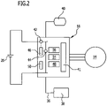
- ein schematisches Blockschaltbild einer Steuereinrichtung des Hochdruckreinigungsgeräts aus
Figur 1 . - In
Figur 1 ist eine bevorzugte Ausführungsform eines erfindungsgemäßen Hochdruckreinigungsgeräts schematisch dargestellt und insgesamt mit dem Bezugszeichen 10 belegt. Das Hochdruckreinigungsgerät 10 weist ein Gehäuse 12 auf, in dem ein Elektromotor 14, eine Pumpe 16 sowie eine Steuereinrichtung 18 und eine wiederaufladbare Batterie 20 angeordnet sind. Der Elektromotor 14 treibt die Pumpe 16 an und wird von der wiederaufladbaren Batterie 20 mit elektrischer Energie versorgt. Die Steuereinrichtung 18 steuert den Elektromotor 14. - Das Hochdruckreinigungsgerät 10 weist ein erstes Anschlusselement 22 und ein zweites Anschlusselement 24 auf. An das erste Anschlusselement 22 kann eine Versorgungsleitung, insbesondere ein Saugschlauch, angeschlossen werden, um die Pumpe 16 mit unter Druck zu setzender Reinigungsflüssigkeit zu versorgen. Eine derartige Versorgungsleitung ist dem Fachmann an sich bekannt und daher in
Figur 1 nicht dargestellt. - An das zweite Anschlusselement 24 ist eine Auslassleitung 26 angeschlossen, die an ihrem freien Ende ein Ausbringorgan 28 mit einer auswechselbaren Düse 30 zum Abgeben der unter Druck gesetzten Reinigungsflüssigkeit trägt. Das Ausbringorgan 28 ist im dargestellten Ausführungsbeispiel als Spritzpistole 32 ausgestaltet und weist einen Hebel 34 auf, der vom Benutzer mit der Hand betätigt werden kann, um die Strömungsverbindung zwischen der Auslassleitung 26 und der Düse 30 wahlweise freizugeben und zu unterbrechen. Gibt der Benutzer die Strömungsverbindung frei, so kann über die Düse 30 ein Reinigungsmittelstrahl auf einen zu reinigenden Gegenstand gerichtet werden, unterbricht der Benutzer die Strömungsverbindung, so wird die Abgabe von Reinigungsflüssigkeit unterbrochen.
- Die Steuereinrichtung 18 steht über eine Signalleitung 36 mit einem Drucksensor 38 in signalleitender Verbindung, mit dem der in der Auslassleitung 26 herrschende Pumpenauslassdruck der Reinigungsflüssigkeit erfasst werden kann. Der Drucksensor 38 kann beispielsweise in Form eines Druckschalters ausgestaltet sein. Dies erlaubt es der Steuereinrichtung 18, den Elektromotor 14 in Abhängigkeit vom Pumpenauslassdruck der Reinigungsflüssigkeit ein- und auszuschalten. Unterbricht der Benutzer mittels der Spritzpistole 32 die Strömungsverbindung zwischen der Auslassleitung 26 und der Düse 30, so steigt der Pumpenauslassdruck der Reinigungsflüssigkeit an. Überschreitet der Druck einen vorgegebenen Ausschaltwert, so wird vom Drucksensor 38 ein Steuersignal an die Steuereinrichtung 18 übertragen, die dadurch veranlasst wird, den Elektromotor 14 auszuschalten. Gibt der Benutzer die Strömungsverbindung zwischen der Auslassleitung 26 und der Düse 30 wieder frei, so fällt der Pumpenauslassdruck der Reinigungsflüssigkeit ab. Unterschreitet der Druck einen vorgegebenen Einschaltwert, so wird vom Drucksensor 38 ein Steuersignal an die Steuereinrichtung 18 übertragen, das die Steuereinrichtung 18 veranlasst, den Elektromotor 14 wieder einzuschalten.
- Der Ladezustand der wiederaufladbaren Batterie 20 wird von der Steuereinrichtung 18 überwacht und kann dem Benutzer an einer Anzeigeeinrichtung 40 des Hochdruckreinigungsgeräts 10 angezeigt werden.
- Die Steuereinrichtung 18 weist im dargestellten Ausführungsbeispiel zwei Betriebsmodi auf, die sich dadurch unterscheiden, dass die Steuereinrichtung 18 den Elektromotor 14 mit unterschiedlicher Drehzahl steuert. In einem ersten Betriebsmodus steuert die Steuereinrichtung 18 den Elektromotor 14 mit einer ersten Drehzahl, und im zweiten Betriebsmodus steuert die Steuereinrichtung 18 den Elektromotor 14 mit einer zweiten Drehzahl, wobei die zweite Drehzahl höher ist als die erste Drehzahl. Die erste Drehzahl kann beispielsweise 16.000 Umdrehungen pro Minute betragen und die zweite Drehzahl kann beispielsweise 18.000 Umdrehungen pro Minute betragen. Zum Umschalten des Betriebsmodus weist die Steuereinrichtung ein steuerbares Schaltglied 41 auf.
- Die Steuereinrichtung 18 weist ein Stromerfassungsglied 42 und ein Spannungserfassungsglied 44 auf. Mit Hilfe des Stromerfassungsglieds 42 wird der von der Batterie 20 bereitgestellte Istwert des Batteriestroms, das heißt der Istwert des Versorgungsstroms des Elektromotors 14 erfasst, und mittels des Spannungserfassungsglieds 44 wird der Istwert der Ausgangsspannung der Batterie 20, das heißt der Istwert der Versorgungsspannung des Elektromotors 14 erfasst. Die Erfassung der Istwerte erfolgt periodisch in Zeitabständen von beispielsweise einer oder zwei Sekunden.
- Vom Stromerfassungsglied 42 wird der Istwert des Batteriestroms an ein Signalverarbeitungsglied 46 übertragen, und vom Spannungserfassungsglied 44 wird der Istwert der Batteriespannung an das Signalverarbeitungsglied 46 übertragen. Der Istwert der Batteriespannung wird vom Signalverarbeitungsglied 46 mit dem Istwert des Batteriestroms multipliziert. Die Multiplikation ergibt den Istwert der elektrischen Leistungsaufnahme des Elektromotors 14.
- Die Leistungsaufnahme des Elektromotors 14 ist von der Größe einer Auslassöffnung 52 der Düse 30 abhängig. Je größer die Auslassöffnung 52 ist, desto geringer ist die elektrische Leistungsaufnahme des Elektromotors 14. Ein Wechsel der Düse 30 hat somit eine Änderung der elektrischen Leistungsaufnahme des Elektromotors 14 zur Folge.
- Nach jedem Start des Elektromotors 14 werden die Istwerte des Versorgungsstroms und der Versorgungsspannung des Elektromotors erfasst und der Istwert der elektrischen Leistungsaufnahme wird berechnet. Der berechnete Istwert der elektrischen Leistungsaufnahme des Elektromotors 14 wird in einem ersten Speicherglied 48 der Steuereinrichtung 18 als Referenzwert gespeichert. Im nachfolgenden Betrieb des Elektromotors 14 werden die Istwerte des Versorgungsstroms und der Versorgungsspannung des Elektromotors 14 periodisch in Zeitabständen von beispielsweise einer oder zwei Sekunden erfasst und der daraus berechnetet aktuelle Istwert der elektrischen Leistungsaufnahme des Elektromotors 14 wird mit Hilfe eines Vergleichsglieds 50 der Steuereinrichtung 18 mit dem im ersten Speicherglied 48 hinterlegten Referenzwert verglichen.
- Erkennt das Vergleichsglied 50 eine einen vorgegebenen Toleranzbereich überschreitende Erhöhung oder Verringerung der elektrischen Leistungsaufnahme des Elektromotors 14, so ändert die Steuereinrichtung 18 ihren Betriebsmodus in Abhängigkeit davon, in welchem Betriebsmodus sie sich aktuell befindet. Außerdem wird nach jeder Änderung der elektrischen Leistungsaufnahme, die den vorgegebenen Toleranzbereich überschreitet, der im ersten Speicherglied 48 hinterlegte Referenzwert durch den nach der Änderung vorliegenden Istwert der Leistungsaufnahme ersetzt, das heißt jede über den vorgegebenen Toleranzbereich hinausgehende Änderung der Leistungsaufnahme führt zu einer Aktualisierung des im ersten Speicherglied 48 gespeicherten Referenzwertes.
- Erkennt das Vergleichsglied 50 keine über den vorgegebenen Toleranzbereich hinausgehende Veränderung der elektrischen Leistungsaufnahme des Elektromotors 14, so bleibt die Steuereinrichtung 18 in ihrem aktuellen Betriebsmodus, so dass die die Drehzahl des Elektromotors 14 unverändert bleibt, und die laufenden Überwachung der elektrischen Leistungsaufnahme wird fortgesetzt.
- Befindet sich die Steuereinrichtung 18 in ihrem ersten Betriebsmodus und erkennt sie mit Hilfe des Vergleichsglieds 50 eine Erhöhung der elektrischen Leistungsaufnahme des Elektromotors 14, die den vorgegebenen Toleranzbereich von beispielsweise 10 Watt überschreitet, so ändert die Steuereinrichtung 18 ihren Betriebsmodus, indem sie in den zweiten Betriebsmodus umschaltet und folglich den Elektromotor 14 mit der höheren zweiten Drehzahl steuert. Der nach erfolgter Änderung vorliegende Istwert der elektrischen Leistungsaufnahme des Elektromotors 14 wird im ersten Speicherglied 48 hinterlegt und dient anschließend während des weiteren Betriebs des Elektromotors 14 als aktualisierter Referenzwert, der vom Vergleichsglied 50 mit dem periodisch neu ermittelten aktuellen Istwert der Leistungsaufnahme verglichen wird.
- Befindet sich die Steuereinrichtung 18 im ersten Betriebsmodus und erkennt sie mit Hilfe des Vergleichsglieds 50 eine Verringerung der elektrischen Leistungsaufnahme des Elektromotors 14, so behält sie ihren ersten Betriebsmodus bei. Es wird aber auch in diesem Fall der nach der erfolgten Änderung der Leistungsaufnahme vorliegende Istwert der Leistungsaufnahme im ersten Speicherglied 48 hinterlegt, der dann anschließend während des weiteren Betriebs des Elektromotors 14 als aktualisierter Referenzwert dient, der vom Vergleichsglied 50 mit dem periodisch neu ermittelten aktuellen Istwert der Leistungsaufnahme verglichen wird.
- Befindet sich die Steuereinrichtung 18 in ihrem zweiten Betriebsmodus und erkennt sie mit Hilfe des Vergleichsglieds 50 eine Erhöhung der elektrischen Leistungsaufnahme des Elektromotors 14, die den vorgegebenen Toleranzbereich überschreitet, so behält sie ihren zweiten Betriebsmodus bei. Wiederum wird der nach der erfolgten Änderung der Leistungsaufnahme vorliegende Istwert der Leistungsaufnahme im ersten Speicherglied 48 hinterlegt und dient anschließend während des weiteren Betriebs des Elektromotors 14 als aktualisierter Referenzwert, der vom Vergleichsglied 50 mit dem periodisch neu ermittelten aktuellen Istwert der Leistungsaufnahme verglichen wird.
- Befindet sich die Steuereinrichtung 18 im zweiten Betriebsmodus und erkennt sie mit Hilfe des Vergleichsglieds 50 eine Verringerung der elektrischen Leistungsaufnahme, die den vorgegebenen Toleranzbereich überschreitet, so schaltet die Steuereinrichtung 18 um in den ersten Betriebsmodus, so dass der Elektromotor 14 anschließend mit der niedrigeren ersten Drehzahl gesteuert wird. Auch in diesem Fall wird der nach der erfolgten Änderung der Leistungsaufnahme vorliegende Istwert der Leistungsaufnahme im ersten Speicherglied 48 hinterlegt und dient anschließend während des weiteren Betriebs des Elektromotors 14 als aktualisierter Referenzwert, der vom Vergleichsglied 50 mit dem periodisch neu ermittelten aktuellen Istwert der Leistungsaufnahme verglichen wird.
- Wird der Elektromotor 14 von der Steuereinrichtung 18 ausgeschaltet, so wird die zuletzt vorliegende Drehzahl des Elektromotors 14 in einem flüchtigen zweiten Speicherglied 54 gespeichert. Darüber hinaus weist die Steuereinrichtung 18 ein nicht-flüchtiges drittes Speicherglied 56 auf, in dem vorzugsweise herstellerseitig eine fest vorgegebene Startdrehzahl des Elektromotors 14 gespeichert wird.
- Wird der Elektromotor 14 nach einer Betriebsunterbrechung von der Steuereinrichtung 18 wieder eingeschaltet, so ruft sie aus dem flüchtigen zweiten Speicherglied 54 die vor dem letzten Ausschalten des Elektromotors 14 vorliegende Drehzahl ab und verwendet diese als Startdrehzahl für den Elektromotor 14. Sollte die im flüchtigen zweiten Speicherglied 54 gespeicherte Drehzahl aufgrund einer länger andauernden Betriebsunterbrechung gelöscht sein, so verwendet die Steuereinrichtung 18 die im nicht-flüchtigen dritten Speicherglied 56 hinterlegte, fest vorgegebene Drehzahl als Startdrehzahl für den Elektromotor 14.
- Falls der Benutzer einen Düsenwechsel vornimmt, indem er die Düse 30 durch eine Düse mit größerer oder kleinerer Auslassöffnung 52 ersetzt, so führt dies zu einer Änderung der elektrischen Leistungsaufnahme des Elektromotors 14. Diese Änderung wird von der Steuereinrichtung 18 erkannt, da sie die Leistungsaufnahme überwacht, indem sie periodisch den Istwert der elektrischen Leistungsaufnahme des Elektromotors 14 mit dem im ersten Speicherglied 48 hinterlegten Referenzwert vergleicht. Je nachdem, in welchem Betriebsmodus sich die Steuereinrichtung 18 gerade befindet und in welcher Weise sich die Leistungsaufnahme ändert, ändert die Steuereinrichtung 18 ihren Betriebsmodus und ändert damit auch die Drehzahl des Elektromotors 14.
Claims (16)
- Steuerverfahren für ein Hochdruckreinigungsgerät (10), das eine Pumpe (16) zum Fördern einer Reinigungsflüssigkeit, einen Elektromotor (14) zum Antreiben der Pumpe (16), eine Steuereinrichtung (18) zum Steuern des Elektromotors (14) sowie ein erstes Anschlusselement (22) zum Anschließen einer Versorgungsleitung für unter Druck zu setzende Reinigungsflüssigkeit und ein zweites Anschlusselement (24) zum Anschließen einer Auslassleitung (26) aufweist, die an ihrem freien Ende ein Ausbringorgan (28) mit einer Düse (30) zum Abgeben der unter Druck gesetzten Reinigungsflüssigkeit trägt, wobei die Steuereinrichtung (18) mehrere Betriebsmodi aufweist, in denen sie den Elektromotor (14) mit jeweils unterschiedlicher Drehzahl steuert, und wobei die Steuereinrichtung (18) die elektrische Leistungsaufnahme des Elektromotors (14) überwacht, dadurch gekennzeichnet, dass die Steuereinrichtung (18) bei einer einen vorgegebenen Toleranzbereich überschreitenden Erhöhung der Leistungsaufnahme des Elektromotors (14) vom aktuell vorliegenden Betriebsmodus in den Betriebsmodus mit der nächst höheren Drehzahl des Elektromotors (14) umschaltet, sofern der aktuelle Betriebsmodus nicht bereits der Betriebsmodus mit der höchsten Drehzahl des Elektromotors (14) ist, und wobei die Steuereinrichtung (18) bei einer einen vorgegebenen Toleranzbereich überschreitenden Verringerung der Leistungsaufnahme des Elektromotors (14) vom aktuell vorliegenden Betriebsmodus in den Betriebsmodus mit der nächst niedrigeren Drehzahl des Elektromotors (14) umschaltet, sofern der aktuelle Betriebsmodus nicht bereits der Betriebsmodus mit der niedrigsten Drehzahl des Elektromotors (14) ist.
- Steuerverfahren nach Anspruch 1, dadurch gekennzeichnet, dass die Steuereinrichtung (18) zwei Betriebsmodi aufweist, wobei sie den Elektromotor (14) im ersten Betriebsmodus mit einer ersten Drehzahl und im zweiten Betriebsmodus mit einer zweiten Drehzahl steuert, wobei die zweite Drehzahl höher ist als die erste Drehzahl.
- Steuerverfahren nach Anspruch 1 oder 2, dadurch gekennzeichnet, dass die Steuereinrichtung (18) den Istwert des Versorgungsstroms und den Istwert der Versorgungsspannung des Elektromotors (14) erfasst und daraus den Istwert der elektrischen Leistungsaufnahme des Elektromotors (14) berechnet.
- Steuerverfahren nach einem der voranstehenden Ansprüche, dadurch gekennzeichnet, dass die Steuereinrichtung (18) nach jedem Start des Elektromotors (14) den sich nach dem Start einstellenden Istwert der Leistungsaufnahme als Referenzwert speichert und nach jeder den Toleranzbereich überschreitenden Änderung der Leistungsaufnahme des Elektromotors (14) den geänderten Istwert der elektrischen Leistungsaufnahme des Elektromotors (14) als Referenzwert speichert und im anschließenden Betrieb des Elektromotors (14) den Istwert der Leistungsaufnahme periodisch neu bestimmt und mit dem zuletzt gespeicherten Referenzwert vergleicht.
- Steuerverfahren nach einem der voranstehenden Ansprüche, dadurch gekennzeichnet, dass die Steuereinrichtung (18) den Elektromotor (14) beim Start mit einer Startdrehzahl steuert, die identisch ist mit der Drehzahl, die beim vorhergehenden Ausschalten des Elektromotors (14) vorlag, oder die fest vorgegeben ist.
- Steuerverfahren nach Anspruch 5, dadurch gekennzeichnet, dass die Steuereinrichtung (18) beim Ausschalten des Elektromotors (14) die zuletzt vorliegende Drehzahl des Elektromotors (14) in einem flüchtigen Speicherglied (54) speichert und bei einem erneuten Start des Elektromotors (14) die zuletzt im flüchtigen Speicherglied (54) gespeicherte Drehzahl als Startdrehzahl heranzieht, sofern das Speicherglied (54) noch nicht gelöscht ist, und ansonsten die fest vorgegebene Startdrehzahl heranzieht, vorzugsweise
dass die fest vorgegebene Startdrehzahl die kleinste Drehzahl des Elektromotors (14) ist. - Steuerverfahren nach einem der voranstehenden Ansprüche, dadurch gekennzeichnet, dass die Steuereinrichtung (18) den Elektromotor (14) ausschaltet, falls der Pumpenauslassdruck der Reinigungsflüssigkeit einen vorgegebenen Ausschaltwert überschreitet, und dass die Steuereinrichtung (18) den Elektromotor (14) wieder einschaltet, wenn der Pumpenauslassdruck der Reinigungsflüssigkeit wieder abfällt.
- Hochdruckreinigungsgerät, das eine Pumpe (16) zum Fördern einer Reinigungsflüssigkeit, einen Elektromotor (14) zum Antreiben der Pumpe (16), eine Steuereinrichtung (18) zum Steuern des Elektromotors (14) sowie ein erstes Anschlusselement (22) zum Anschließen einer Versorgungsleitung für unter Druck zu setzende Reinigungsflüssigkeit und ein zweites Anschlusselement (24) zum Anschließen einer Auslassleitung (26) aufweist, die an ihrem freien Ende ein Ausbringorgan (28) mit einer Düse (30) zum Abgeben der unter Druck gesetzten Reinigungsflüssigkeit trägt, insbesondere zur Durchführung des Steuerverfahrens nach einem der voranstehenden Ansprüche, wobei die Steuereinrichtung (18) mehrere Betriebsmodi aufweist, in denen sie den Elektromotor (14) mit jeweils unterschiedlicher Drehzahl steuert, und wobei die Steuereinrichtung (18) eingerichtet ist, die elektrische Leistungsaufnahme des Elektromotors (14) zu überwachen, dadurch gekennzeichnet, dass die Steuereinrichtung (18) eingerichtet ist, bei einer einen vorgegebenen Toleranzbereich überschreitenden Erhöhung der Leistungsaufnahme des Elektromotors (14) vom aktuell vorliegenden Betriebsmodus in den Betriebsmodus mit der nächst höheren Drehzahl des Elektromotors (14) umzuschalten, sofern der aktuelle Betriebsmodus nicht bereits der Betriebsmodus mit der höchsten Drehzahl des Elektromotors (14) ist, und wobei die Steuereinrichtung (18) eingerichtet ist, bei einer einen vorgegebenen Toleranzbereich überschreitenden Verringerung der Leistungsaufnahme des Elektromotors (14) vom aktuell vorliegenden Betriebsmodus in den Betriebsmodus mit der nächst niedrigeren Drehzahl des Elektromotors (14) umzuschalten, sofern der aktuelle Betriebsmodus nicht bereits der Betriebsmodus mit der niedrigsten Drehzahl des Elektromotors (14) ist.
- Hochdruckreinigungsgerät nach Anspruch 8, dadurch gekennzeichnet, dass die Steuereinrichtung zwei Betriebsmodi aufweist, wobei sie den Elektromotor (14) im ersten Betriebsmodus mit einer ersten Drehzahl und im zweiten Betriebsmodus mit einer zweiten Drehzahl steuert, wobei die zweite Drehzahl höher ist als die erste Drehzahl.
- Hochdruckreinigungsgerät nach Anspruch 8 oder 9, dadurch gekennzeichnet, dass die Steuereinrichtung (18) ein Stromerfassungsglied (42) zur Erfassung des Istwerts des Versorgungsstroms des Elektromotors (14) und ein Spannungserfassungsglied (44) zur Erfassung des Istwerts der Versorgungsspannung des Elektromotors (14) aufweist, und dass die Steuereinrichtung (18) eingerichtet ist, aus den Istwerten des Versorgungsstroms und der Versorgungsspannung den Istwert der elektrischen Leistungsaufnahme des Elektromotors (14) zu berechnen.
- Hochdruckreinigungsgerät nach einem der Ansprüche 8 bis 10, dadurch gekennzeichnet, dass die Steuereinrichtung (18) ein erstes Speicherglied (48) aufweist zum Speichern eines Referenzwertes der Leistungsaufnahme des Elektromotors (14), und dass die Steuereinrichtung (18) ein Vergleichsglied (50) aufweist zum Vergleichen des Referenzwertes mit dem aktuellen Istwert der Leistungsaufnahme des Elektromotors (14).
- Hochdruckreinigungsgerät nach Anspruch 11, dadurch gekennzeichnet, dass die Steuereinrichtung (18) eingerichtet ist, nach jedem Start des Elektromotors (14) den sich nach dem Start einstellenden Istwert der Leistungsaufnahme als Referenzwert zu speichern und nach jeder den Toleranzbereich überschreitenden Änderung der Leistungsaufnahme des Elektromotors (14) den geänderten Istwert der elektrischen Leistungsaufnahme des Elektromotors (14) als Referenzwert zu speichern und im anschließenden Betrieb des Elektromotors (14) den Istwert der Leistungsaufnahme periodisch neu zu bestimmen und mit dem zuletzt gespeicherten Referenzwert zu vergleichen.
- Hochdruckreinigungsgerät nach einem der Ansprüche 8 bis 12, dadurch gekennzeichnet, dass die Steuereinrichtung (18) ein flüchtiges Speicherglied (54) aufweist zum Speichern der Drehzahl des Elektromotors (14).
- Hochdruckreinigungsgerät nach einem der Ansprüche 8 bis 13, dadurch gekennzeichnet, dass die Steuereinrichtung (18) ein nicht-flüchtiges Speicherglied (56) aufweist zum Speichern einer fest vorgegebenen Startdrehzahl des Elektromotors (14).
- Hochdruckreinigungsgerät nach einem der Ansprüche 8 bis 14, dadurch gekennzeichnet, dass der Elektromotor (14) von der Steuereinrichtung (18) ausschaltbar ist, wenn der Pumpenauslassdruck der Reinigungsflüssigkeit einen vorgegebenen Ausschaltwert überschreitet, und dass der Elektromotor (14) von der Steuereinrichtung (18) wiedereinschaltbar ist, wenn der Pumpenauslassdruck der Reinigungsflüssigkeit wieder abfällt.
- Hochdruckreinigungsgerät nach einem der Ansprüche 8 bis 15, dadurch gekennzeichnet, dass das Hochdruckreinigungsgerät (10) mindestens eine wiederaufladbare Batterie (20) zur Energieversorgung des Elektromotors (14) aufweist.
Applications Claiming Priority (1)
| Application Number | Priority Date | Filing Date | Title |
|---|---|---|---|
| PCT/EP2018/055965 WO2019170255A1 (de) | 2018-03-09 | 2018-03-09 | Steuerverfahren für ein hochdruckreinigungsgerät und hochdruckreinigungsgerät insbesondere zur durchführung des verfahrens |
Publications (2)
| Publication Number | Publication Date |
|---|---|
| EP3762156A1 EP3762156A1 (de) | 2021-01-13 |
| EP3762156B1 true EP3762156B1 (de) | 2022-06-08 |
Family
ID=61628344
Family Applications (1)
| Application Number | Title | Priority Date | Filing Date |
|---|---|---|---|
| EP18711072.1A Active EP3762156B1 (de) | 2018-03-09 | 2018-03-09 | Steuerverfahren für ein hochdruckreinigungsgerät und hochdruckreinigungsgerät insbesondere zur durchführung des verfahrens |
Country Status (3)
| Country | Link |
|---|---|
| EP (1) | EP3762156B1 (de) |
| CN (1) | CN111788015B (de) |
| WO (1) | WO2019170255A1 (de) |
Family Cites Families (7)
| Publication number | Priority date | Publication date | Assignee | Title |
|---|---|---|---|---|
| DE3210082A1 (de) * | 1981-04-02 | 1982-10-21 | IWE Ingenieurgesellschaft für wirtschaftliche Energienutzung mbH, 6078 Neu-Isenburg | Verfahren und schaltungsanordnung zur regelung der drehzahl eines pumpenmotors |
| DE9013486U1 (de) * | 1990-09-25 | 1990-11-29 | Alfred Kärcher GmbH & Co, 7057 Winnenden | Hochdruckreinigungsgerät |
| DE4211788C2 (de) * | 1992-04-08 | 1994-03-10 | Kaercher Gmbh & Co Alfred | Hochdruckreinigungsgerät |
| DE102004003536A1 (de) * | 2004-01-23 | 2005-08-11 | BSH Bosch und Siemens Hausgeräte GmbH | Flüssigkeitsführendes elektrisches Haushaltsgerät |
| EP3159541A4 (de) * | 2014-06-20 | 2018-04-11 | Hitachi Koki Co., Ltd. | Flüssigkeitsausstossvorrichtung |
| CN106914439B (zh) * | 2015-12-28 | 2021-01-05 | 苏州宝时得电动工具有限公司 | 压力清洗机 |
| CN107051939B (zh) * | 2016-11-22 | 2019-12-24 | 常州格力博有限公司 | 自反馈式清洗机及其控制方式 |
-
2018
- 2018-03-09 CN CN201880090464.2A patent/CN111788015B/zh active Active
- 2018-03-09 WO PCT/EP2018/055965 patent/WO2019170255A1/de not_active Ceased
- 2018-03-09 EP EP18711072.1A patent/EP3762156B1/de active Active
Also Published As
| Publication number | Publication date |
|---|---|
| EP3762156A1 (de) | 2021-01-13 |
| CN111788015B (zh) | 2023-02-03 |
| WO2019170255A1 (de) | 2019-09-12 |
| CN111788015A (zh) | 2020-10-16 |
Similar Documents
| Publication | Publication Date | Title |
|---|---|---|
| DE69510221T2 (de) | Vorrichtung zur stromunterbrechung von stromverbrauchern wie stellglieder | |
| EP1926122B1 (de) | Verfahren zum Erkennen einer Bogenentladung in einem Plasmaprozess und Bogenentladungserkennungsvorrichtung | |
| EP3791070B1 (de) | Verfahren zum betrieb einer fördervorrichtung und fördervorrichtung | |
| EP2314384B1 (de) | Auspressvorrichtung | |
| DE202013101730U1 (de) | Druckreiniger | |
| EP1901411A2 (de) | Verfahren zur Steuerung eines Motors eines akkubetriebenen Werkzeuggerätes | |
| WO2016095988A1 (de) | Hochdruckreinigungssystem | |
| DE102017206504A1 (de) | Druckreinigungsvorrichtung mit einer Druckerzeugungseinheit | |
| DE102005028116A1 (de) | Verfahren zum Steuern eines Reinigungsgerätes und Reinigungsgerät zur Durchführung des Verfahrens | |
| EP3749466B1 (de) | Verfahren zum steuern eines hochdruckreinigungsgeräts und hochdruckreinigungsgerät insbesondere zur durchführung des verfahrens | |
| EP3762156B1 (de) | Steuerverfahren für ein hochdruckreinigungsgerät und hochdruckreinigungsgerät insbesondere zur durchführung des verfahrens | |
| EP3156656B1 (de) | Pumpensteuerverfahren und druckerhöhungsvorrichtung | |
| EP1764020B1 (de) | Sauggerät | |
| EP2591236B1 (de) | Gartenpumpenanordnung mit durchflusssensor | |
| EP2192685B1 (de) | Vorrichtung und verfahren zur autoparametrierung eines elektronischen motorsteuergerätes | |
| WO2024156395A1 (de) | Verfahren zum steuern eines reinigungsgeräts und reinigungsgerät insbesondere zur durchführung des verfahrens | |
| EP2747908B1 (de) | Hochdruckreinigungsgerät | |
| DE202014011460U1 (de) | Hochdruckreinigungssystem | |
| AT405624B (de) | Schweissgerät und schweissverfahren, insbesondere widerstandsschweissverfahren | |
| EP2886727B1 (de) | Sanitärarmatur und Verfahren zur Energiezufuhr derselben | |
| WO2007045259A1 (de) | Hochdruckreinigungsgerät | |
| EP2436294B1 (de) | Staubsauger und Verfahren zum Betrieb eines Staubsaugers | |
| EP4452530A1 (de) | Elektrisch betriebenes hochdruckreinigungsgerät | |
| EP1744850B1 (de) | Wasserdampf-schneidgerät | |
| WO2019057276A1 (de) | Hochdruckreinigungsgerät |
Legal Events
| Date | Code | Title | Description |
|---|---|---|---|
| STAA | Information on the status of an ep patent application or granted ep patent |
Free format text: STATUS: UNKNOWN |
|
| STAA | Information on the status of an ep patent application or granted ep patent |
Free format text: STATUS: THE INTERNATIONAL PUBLICATION HAS BEEN MADE |
|
| PUAI | Public reference made under article 153(3) epc to a published international application that has entered the european phase |
Free format text: ORIGINAL CODE: 0009012 |
|
| STAA | Information on the status of an ep patent application or granted ep patent |
Free format text: STATUS: REQUEST FOR EXAMINATION WAS MADE |
|
| 17P | Request for examination filed |
Effective date: 20200811 |
|
| AK | Designated contracting states |
Kind code of ref document: A1 Designated state(s): AL AT BE BG CH CY CZ DE DK EE ES FI FR GB GR HR HU IE IS IT LI LT LU LV MC MK MT NL NO PL PT RO RS SE SI SK SM TR |
|
| AX | Request for extension of the european patent |
Extension state: BA ME |
|
| DAV | Request for validation of the european patent (deleted) | ||
| DAX | Request for extension of the european patent (deleted) | ||
| GRAP | Despatch of communication of intention to grant a patent |
Free format text: ORIGINAL CODE: EPIDOSNIGR1 |
|
| STAA | Information on the status of an ep patent application or granted ep patent |
Free format text: STATUS: GRANT OF PATENT IS INTENDED |
|
| GRAJ | Information related to disapproval of communication of intention to grant by the applicant or resumption of examination proceedings by the epo deleted |
Free format text: ORIGINAL CODE: EPIDOSDIGR1 |
|
| STAA | Information on the status of an ep patent application or granted ep patent |
Free format text: STATUS: REQUEST FOR EXAMINATION WAS MADE |
|
| INTG | Intention to grant announced |
Effective date: 20211115 |
|
| INTC | Intention to grant announced (deleted) | ||
| GRAP | Despatch of communication of intention to grant a patent |
Free format text: ORIGINAL CODE: EPIDOSNIGR1 |
|
| STAA | Information on the status of an ep patent application or granted ep patent |
Free format text: STATUS: GRANT OF PATENT IS INTENDED |
|
| INTG | Intention to grant announced |
Effective date: 20220110 |
|
| GRAS | Grant fee paid |
Free format text: ORIGINAL CODE: EPIDOSNIGR3 |
|
| GRAA | (expected) grant |
Free format text: ORIGINAL CODE: 0009210 |
|
| STAA | Information on the status of an ep patent application or granted ep patent |
Free format text: STATUS: THE PATENT HAS BEEN GRANTED |
|
| AK | Designated contracting states |
Kind code of ref document: B1 Designated state(s): AL AT BE BG CH CY CZ DE DK EE ES FI FR GB GR HR HU IE IS IT LI LT LU LV MC MK MT NL NO PL PT RO RS SE SI SK SM TR |
|
| REG | Reference to a national code |
Ref country code: AT Ref legal event code: REF Ref document number: 1496557 Country of ref document: AT Kind code of ref document: T Effective date: 20220615 Ref country code: CH Ref legal event code: EP |
|
| REG | Reference to a national code |
Ref country code: DE Ref legal event code: R096 Ref document number: 502018009867 Country of ref document: DE |
|
| REG | Reference to a national code |
Ref country code: IE Ref legal event code: FG4D Free format text: LANGUAGE OF EP DOCUMENT: GERMAN |
|
| REG | Reference to a national code |
Ref country code: LT Ref legal event code: MG9D |
|
| REG | Reference to a national code |
Ref country code: NL Ref legal event code: MP Effective date: 20220608 |
|
| PG25 | Lapsed in a contracting state [announced via postgrant information from national office to epo] |
Ref country code: SE Free format text: LAPSE BECAUSE OF FAILURE TO SUBMIT A TRANSLATION OF THE DESCRIPTION OR TO PAY THE FEE WITHIN THE PRESCRIBED TIME-LIMIT Effective date: 20220608 Ref country code: NO Free format text: LAPSE BECAUSE OF FAILURE TO SUBMIT A TRANSLATION OF THE DESCRIPTION OR TO PAY THE FEE WITHIN THE PRESCRIBED TIME-LIMIT Effective date: 20220908 Ref country code: LT Free format text: LAPSE BECAUSE OF FAILURE TO SUBMIT A TRANSLATION OF THE DESCRIPTION OR TO PAY THE FEE WITHIN THE PRESCRIBED TIME-LIMIT Effective date: 20220608 Ref country code: HR Free format text: LAPSE BECAUSE OF FAILURE TO SUBMIT A TRANSLATION OF THE DESCRIPTION OR TO PAY THE FEE WITHIN THE PRESCRIBED TIME-LIMIT Effective date: 20220608 Ref country code: GR Free format text: LAPSE BECAUSE OF FAILURE TO SUBMIT A TRANSLATION OF THE DESCRIPTION OR TO PAY THE FEE WITHIN THE PRESCRIBED TIME-LIMIT Effective date: 20220909 Ref country code: FI Free format text: LAPSE BECAUSE OF FAILURE TO SUBMIT A TRANSLATION OF THE DESCRIPTION OR TO PAY THE FEE WITHIN THE PRESCRIBED TIME-LIMIT Effective date: 20220608 Ref country code: BG Free format text: LAPSE BECAUSE OF FAILURE TO SUBMIT A TRANSLATION OF THE DESCRIPTION OR TO PAY THE FEE WITHIN THE PRESCRIBED TIME-LIMIT Effective date: 20220908 |
|
| PG25 | Lapsed in a contracting state [announced via postgrant information from national office to epo] |
Ref country code: RS Free format text: LAPSE BECAUSE OF FAILURE TO SUBMIT A TRANSLATION OF THE DESCRIPTION OR TO PAY THE FEE WITHIN THE PRESCRIBED TIME-LIMIT Effective date: 20220608 Ref country code: LV Free format text: LAPSE BECAUSE OF FAILURE TO SUBMIT A TRANSLATION OF THE DESCRIPTION OR TO PAY THE FEE WITHIN THE PRESCRIBED TIME-LIMIT Effective date: 20220608 |
|
| PG25 | Lapsed in a contracting state [announced via postgrant information from national office to epo] |
Ref country code: NL Free format text: LAPSE BECAUSE OF FAILURE TO SUBMIT A TRANSLATION OF THE DESCRIPTION OR TO PAY THE FEE WITHIN THE PRESCRIBED TIME-LIMIT Effective date: 20220608 |
|
| PG25 | Lapsed in a contracting state [announced via postgrant information from national office to epo] |
Ref country code: SM Free format text: LAPSE BECAUSE OF FAILURE TO SUBMIT A TRANSLATION OF THE DESCRIPTION OR TO PAY THE FEE WITHIN THE PRESCRIBED TIME-LIMIT Effective date: 20220608 Ref country code: SK Free format text: LAPSE BECAUSE OF FAILURE TO SUBMIT A TRANSLATION OF THE DESCRIPTION OR TO PAY THE FEE WITHIN THE PRESCRIBED TIME-LIMIT Effective date: 20220608 Ref country code: RO Free format text: LAPSE BECAUSE OF FAILURE TO SUBMIT A TRANSLATION OF THE DESCRIPTION OR TO PAY THE FEE WITHIN THE PRESCRIBED TIME-LIMIT Effective date: 20220608 Ref country code: PT Free format text: LAPSE BECAUSE OF FAILURE TO SUBMIT A TRANSLATION OF THE DESCRIPTION OR TO PAY THE FEE WITHIN THE PRESCRIBED TIME-LIMIT Effective date: 20221010 Ref country code: ES Free format text: LAPSE BECAUSE OF FAILURE TO SUBMIT A TRANSLATION OF THE DESCRIPTION OR TO PAY THE FEE WITHIN THE PRESCRIBED TIME-LIMIT Effective date: 20220608 Ref country code: EE Free format text: LAPSE BECAUSE OF FAILURE TO SUBMIT A TRANSLATION OF THE DESCRIPTION OR TO PAY THE FEE WITHIN THE PRESCRIBED TIME-LIMIT Effective date: 20220608 Ref country code: CZ Free format text: LAPSE BECAUSE OF FAILURE TO SUBMIT A TRANSLATION OF THE DESCRIPTION OR TO PAY THE FEE WITHIN THE PRESCRIBED TIME-LIMIT Effective date: 20220608 |
|
| PG25 | Lapsed in a contracting state [announced via postgrant information from national office to epo] |
Ref country code: PL Free format text: LAPSE BECAUSE OF FAILURE TO SUBMIT A TRANSLATION OF THE DESCRIPTION OR TO PAY THE FEE WITHIN THE PRESCRIBED TIME-LIMIT Effective date: 20220608 Ref country code: IS Free format text: LAPSE BECAUSE OF FAILURE TO SUBMIT A TRANSLATION OF THE DESCRIPTION OR TO PAY THE FEE WITHIN THE PRESCRIBED TIME-LIMIT Effective date: 20221008 |
|
| REG | Reference to a national code |
Ref country code: DE Ref legal event code: R097 Ref document number: 502018009867 Country of ref document: DE |
|
| PG25 | Lapsed in a contracting state [announced via postgrant information from national office to epo] |
Ref country code: AL Free format text: LAPSE BECAUSE OF FAILURE TO SUBMIT A TRANSLATION OF THE DESCRIPTION OR TO PAY THE FEE WITHIN THE PRESCRIBED TIME-LIMIT Effective date: 20220608 |
|
| PLBE | No opposition filed within time limit |
Free format text: ORIGINAL CODE: 0009261 |
|
| STAA | Information on the status of an ep patent application or granted ep patent |
Free format text: STATUS: NO OPPOSITION FILED WITHIN TIME LIMIT |
|
| PG25 | Lapsed in a contracting state [announced via postgrant information from national office to epo] |
Ref country code: DK Free format text: LAPSE BECAUSE OF FAILURE TO SUBMIT A TRANSLATION OF THE DESCRIPTION OR TO PAY THE FEE WITHIN THE PRESCRIBED TIME-LIMIT Effective date: 20220608 |
|
| 26N | No opposition filed |
Effective date: 20230310 |
|
| PG25 | Lapsed in a contracting state [announced via postgrant information from national office to epo] |
Ref country code: SI Free format text: LAPSE BECAUSE OF FAILURE TO SUBMIT A TRANSLATION OF THE DESCRIPTION OR TO PAY THE FEE WITHIN THE PRESCRIBED TIME-LIMIT Effective date: 20220608 |
|
| P01 | Opt-out of the competence of the unified patent court (upc) registered |
Effective date: 20230521 |
|
| PG25 | Lapsed in a contracting state [announced via postgrant information from national office to epo] |
Ref country code: MC Free format text: LAPSE BECAUSE OF FAILURE TO SUBMIT A TRANSLATION OF THE DESCRIPTION OR TO PAY THE FEE WITHIN THE PRESCRIBED TIME-LIMIT Effective date: 20220608 |
|
| REG | Reference to a national code |
Ref country code: CH Ref legal event code: PL |
|
| REG | Reference to a national code |
Ref country code: BE Ref legal event code: MM Effective date: 20230331 |
|
| PG25 | Lapsed in a contracting state [announced via postgrant information from national office to epo] |
Ref country code: LU Free format text: LAPSE BECAUSE OF NON-PAYMENT OF DUE FEES Effective date: 20230309 |
|
| REG | Reference to a national code |
Ref country code: IE Ref legal event code: MM4A |
|
| PG25 | Lapsed in a contracting state [announced via postgrant information from national office to epo] |
Ref country code: LI Free format text: LAPSE BECAUSE OF NON-PAYMENT OF DUE FEES Effective date: 20230331 Ref country code: IE Free format text: LAPSE BECAUSE OF NON-PAYMENT OF DUE FEES Effective date: 20230309 Ref country code: CH Free format text: LAPSE BECAUSE OF NON-PAYMENT OF DUE FEES Effective date: 20230331 |
|
| PG25 | Lapsed in a contracting state [announced via postgrant information from national office to epo] |
Ref country code: BE Free format text: LAPSE BECAUSE OF NON-PAYMENT OF DUE FEES Effective date: 20230331 |
|
| REG | Reference to a national code |
Ref country code: AT Ref legal event code: MM01 Ref document number: 1496557 Country of ref document: AT Kind code of ref document: T Effective date: 20230309 |
|
| PG25 | Lapsed in a contracting state [announced via postgrant information from national office to epo] |
Ref country code: AT Free format text: LAPSE BECAUSE OF NON-PAYMENT OF DUE FEES Effective date: 20230309 |
|
| PG25 | Lapsed in a contracting state [announced via postgrant information from national office to epo] |
Ref country code: AT Free format text: LAPSE BECAUSE OF NON-PAYMENT OF DUE FEES Effective date: 20230309 |
|
| PG25 | Lapsed in a contracting state [announced via postgrant information from national office to epo] |
Ref country code: BG Free format text: LAPSE BECAUSE OF FAILURE TO SUBMIT A TRANSLATION OF THE DESCRIPTION OR TO PAY THE FEE WITHIN THE PRESCRIBED TIME-LIMIT Effective date: 20220608 |
|
| PG25 | Lapsed in a contracting state [announced via postgrant information from national office to epo] |
Ref country code: BG Free format text: LAPSE BECAUSE OF FAILURE TO SUBMIT A TRANSLATION OF THE DESCRIPTION OR TO PAY THE FEE WITHIN THE PRESCRIBED TIME-LIMIT Effective date: 20220608 |
|
| PG25 | Lapsed in a contracting state [announced via postgrant information from national office to epo] |
Ref country code: CY Free format text: LAPSE BECAUSE OF FAILURE TO SUBMIT A TRANSLATION OF THE DESCRIPTION OR TO PAY THE FEE WITHIN THE PRESCRIBED TIME-LIMIT; INVALID AB INITIO Effective date: 20180309 |
|
| PG25 | Lapsed in a contracting state [announced via postgrant information from national office to epo] |
Ref country code: HU Free format text: LAPSE BECAUSE OF FAILURE TO SUBMIT A TRANSLATION OF THE DESCRIPTION OR TO PAY THE FEE WITHIN THE PRESCRIBED TIME-LIMIT; INVALID AB INITIO Effective date: 20180309 |
|
| PG25 | Lapsed in a contracting state [announced via postgrant information from national office to epo] |
Ref country code: TR Free format text: LAPSE BECAUSE OF FAILURE TO SUBMIT A TRANSLATION OF THE DESCRIPTION OR TO PAY THE FEE WITHIN THE PRESCRIBED TIME-LIMIT Effective date: 20220608 |
|
| PGFP | Annual fee paid to national office [announced via postgrant information from national office to epo] |
Ref country code: GB Payment date: 20260209 Year of fee payment: 9 |
|
| PGFP | Annual fee paid to national office [announced via postgrant information from national office to epo] |
Ref country code: DE Payment date: 20260203 Year of fee payment: 9 |
|
| PGFP | Annual fee paid to national office [announced via postgrant information from national office to epo] |
Ref country code: IT Payment date: 20260220 Year of fee payment: 9 |
|
| PGFP | Annual fee paid to national office [announced via postgrant information from national office to epo] |
Ref country code: FR Payment date: 20260209 Year of fee payment: 9 |