EP3762212B1 - 3d-drucker-einweg-patrone - Google Patents
3d-drucker-einweg-patrone Download PDFInfo
- Publication number
- EP3762212B1 EP3762212B1 EP19710585.1A EP19710585A EP3762212B1 EP 3762212 B1 EP3762212 B1 EP 3762212B1 EP 19710585 A EP19710585 A EP 19710585A EP 3762212 B1 EP3762212 B1 EP 3762212B1
- Authority
- EP
- European Patent Office
- Prior art keywords
- cartridge
- casing part
- liquid
- housing part
- exposure device
- Prior art date
- Legal status (The legal status is an assumption and is not a legal conclusion. Google has not performed a legal analysis and makes no representation as to the accuracy of the status listed.)
- Active
Links
Images

Classifications
-
- B—PERFORMING OPERATIONS; TRANSPORTING
- B29—WORKING OF PLASTICS; WORKING OF SUBSTANCES IN A PLASTIC STATE IN GENERAL
- B29C—SHAPING OR JOINING OF PLASTICS; SHAPING OF MATERIAL IN A PLASTIC STATE, NOT OTHERWISE PROVIDED FOR; AFTER-TREATMENT OF THE SHAPED PRODUCTS, e.g. REPAIRING
- B29C64/00—Additive manufacturing, i.e. manufacturing of three-dimensional [3D] objects by additive deposition, additive agglomeration or additive layering, e.g. by 3D printing, stereolithography or selective laser sintering
- B29C64/10—Processes of additive manufacturing
- B29C64/106—Processes of additive manufacturing using only liquids or viscous materials, e.g. depositing a continuous bead of viscous material
- B29C64/124—Processes of additive manufacturing using only liquids or viscous materials, e.g. depositing a continuous bead of viscous material using layers of liquid which are selectively solidified
-
- A—HUMAN NECESSITIES
- A61—MEDICAL OR VETERINARY SCIENCE; HYGIENE
- A61C—DENTISTRY; APPARATUS OR METHODS FOR ORAL OR DENTAL HYGIENE
- A61C13/00—Dental prostheses; Making same
- A61C13/0003—Making bridge-work, inlays, implants or the like
- A61C13/0006—Production methods
- A61C13/0019—Production methods using three dimensional printing
-
- B—PERFORMING OPERATIONS; TRANSPORTING
- B29—WORKING OF PLASTICS; WORKING OF SUBSTANCES IN A PLASTIC STATE IN GENERAL
- B29C—SHAPING OR JOINING OF PLASTICS; SHAPING OF MATERIAL IN A PLASTIC STATE, NOT OTHERWISE PROVIDED FOR; AFTER-TREATMENT OF THE SHAPED PRODUCTS, e.g. REPAIRING
- B29C64/00—Additive manufacturing, i.e. manufacturing of three-dimensional [3D] objects by additive deposition, additive agglomeration or additive layering, e.g. by 3D printing, stereolithography or selective laser sintering
- B29C64/10—Processes of additive manufacturing
- B29C64/106—Processes of additive manufacturing using only liquids or viscous materials, e.g. depositing a continuous bead of viscous material
- B29C64/112—Processes of additive manufacturing using only liquids or viscous materials, e.g. depositing a continuous bead of viscous material using individual droplets, e.g. from jetting heads
-
- B—PERFORMING OPERATIONS; TRANSPORTING
- B29—WORKING OF PLASTICS; WORKING OF SUBSTANCES IN A PLASTIC STATE IN GENERAL
- B29C—SHAPING OR JOINING OF PLASTICS; SHAPING OF MATERIAL IN A PLASTIC STATE, NOT OTHERWISE PROVIDED FOR; AFTER-TREATMENT OF THE SHAPED PRODUCTS, e.g. REPAIRING
- B29C64/00—Additive manufacturing, i.e. manufacturing of three-dimensional [3D] objects by additive deposition, additive agglomeration or additive layering, e.g. by 3D printing, stereolithography or selective laser sintering
- B29C64/20—Apparatus for additive manufacturing; Details thereof or accessories therefor
- B29C64/245—Platforms or substrates
-
- B—PERFORMING OPERATIONS; TRANSPORTING
- B29—WORKING OF PLASTICS; WORKING OF SUBSTANCES IN A PLASTIC STATE IN GENERAL
- B29C—SHAPING OR JOINING OF PLASTICS; SHAPING OF MATERIAL IN A PLASTIC STATE, NOT OTHERWISE PROVIDED FOR; AFTER-TREATMENT OF THE SHAPED PRODUCTS, e.g. REPAIRING
- B29C64/00—Additive manufacturing, i.e. manufacturing of three-dimensional [3D] objects by additive deposition, additive agglomeration or additive layering, e.g. by 3D printing, stereolithography or selective laser sintering
- B29C64/20—Apparatus for additive manufacturing; Details thereof or accessories therefor
- B29C64/25—Housings, e.g. machine housings
-
- B—PERFORMING OPERATIONS; TRANSPORTING
- B29—WORKING OF PLASTICS; WORKING OF SUBSTANCES IN A PLASTIC STATE IN GENERAL
- B29C—SHAPING OR JOINING OF PLASTICS; SHAPING OF MATERIAL IN A PLASTIC STATE, NOT OTHERWISE PROVIDED FOR; AFTER-TREATMENT OF THE SHAPED PRODUCTS, e.g. REPAIRING
- B29C64/00—Additive manufacturing, i.e. manufacturing of three-dimensional [3D] objects by additive deposition, additive agglomeration or additive layering, e.g. by 3D printing, stereolithography or selective laser sintering
- B29C64/20—Apparatus for additive manufacturing; Details thereof or accessories therefor
- B29C64/255—Enclosures for the building material, e.g. powder containers
-
- B—PERFORMING OPERATIONS; TRANSPORTING
- B29—WORKING OF PLASTICS; WORKING OF SUBSTANCES IN A PLASTIC STATE IN GENERAL
- B29C—SHAPING OR JOINING OF PLASTICS; SHAPING OF MATERIAL IN A PLASTIC STATE, NOT OTHERWISE PROVIDED FOR; AFTER-TREATMENT OF THE SHAPED PRODUCTS, e.g. REPAIRING
- B29C64/00—Additive manufacturing, i.e. manufacturing of three-dimensional [3D] objects by additive deposition, additive agglomeration or additive layering, e.g. by 3D printing, stereolithography or selective laser sintering
- B29C64/20—Apparatus for additive manufacturing; Details thereof or accessories therefor
- B29C64/255—Enclosures for the building material, e.g. powder containers
- B29C64/259—Interchangeable
-
- B—PERFORMING OPERATIONS; TRANSPORTING
- B29—WORKING OF PLASTICS; WORKING OF SUBSTANCES IN A PLASTIC STATE IN GENERAL
- B29C—SHAPING OR JOINING OF PLASTICS; SHAPING OF MATERIAL IN A PLASTIC STATE, NOT OTHERWISE PROVIDED FOR; AFTER-TREATMENT OF THE SHAPED PRODUCTS, e.g. REPAIRING
- B29C64/00—Additive manufacturing, i.e. manufacturing of three-dimensional [3D] objects by additive deposition, additive agglomeration or additive layering, e.g. by 3D printing, stereolithography or selective laser sintering
- B29C64/20—Apparatus for additive manufacturing; Details thereof or accessories therefor
- B29C64/264—Arrangements for irradiation
-
- B—PERFORMING OPERATIONS; TRANSPORTING
- B29—WORKING OF PLASTICS; WORKING OF SUBSTANCES IN A PLASTIC STATE IN GENERAL
- B29C—SHAPING OR JOINING OF PLASTICS; SHAPING OF MATERIAL IN A PLASTIC STATE, NOT OTHERWISE PROVIDED FOR; AFTER-TREATMENT OF THE SHAPED PRODUCTS, e.g. REPAIRING
- B29C64/00—Additive manufacturing, i.e. manufacturing of three-dimensional [3D] objects by additive deposition, additive agglomeration or additive layering, e.g. by 3D printing, stereolithography or selective laser sintering
- B29C64/30—Auxiliary operations or equipment
- B29C64/307—Handling of material to be used in additive manufacturing
- B29C64/321—Feeding
-
- B—PERFORMING OPERATIONS; TRANSPORTING
- B33—ADDITIVE MANUFACTURING TECHNOLOGY
- B33Y—ADDITIVE MANUFACTURING, i.e. MANUFACTURING OF THREE-DIMENSIONAL [3D] OBJECTS BY ADDITIVE DEPOSITION, ADDITIVE AGGLOMERATION OR ADDITIVE LAYERING, e.g. BY 3D PRINTING, STEREOLITHOGRAPHY OR SELECTIVE LASER SINTERING
- B33Y10/00—Processes of additive manufacturing
-
- B—PERFORMING OPERATIONS; TRANSPORTING
- B33—ADDITIVE MANUFACTURING TECHNOLOGY
- B33Y—ADDITIVE MANUFACTURING, i.e. MANUFACTURING OF THREE-DIMENSIONAL [3D] OBJECTS BY ADDITIVE DEPOSITION, ADDITIVE AGGLOMERATION OR ADDITIVE LAYERING, e.g. BY 3D PRINTING, STEREOLITHOGRAPHY OR SELECTIVE LASER SINTERING
- B33Y30/00—Apparatus for additive manufacturing; Details thereof or accessories therefor
-
- B—PERFORMING OPERATIONS; TRANSPORTING
- B33—ADDITIVE MANUFACTURING TECHNOLOGY
- B33Y—ADDITIVE MANUFACTURING, i.e. MANUFACTURING OF THREE-DIMENSIONAL [3D] OBJECTS BY ADDITIVE DEPOSITION, ADDITIVE AGGLOMERATION OR ADDITIVE LAYERING, e.g. BY 3D PRINTING, STEREOLITHOGRAPHY OR SELECTIVE LASER SINTERING
- B33Y70/00—Materials specially adapted for additive manufacturing
-
- B—PERFORMING OPERATIONS; TRANSPORTING
- B33—ADDITIVE MANUFACTURING TECHNOLOGY
- B33Y—ADDITIVE MANUFACTURING, i.e. MANUFACTURING OF THREE-DIMENSIONAL [3D] OBJECTS BY ADDITIVE DEPOSITION, ADDITIVE AGGLOMERATION OR ADDITIVE LAYERING, e.g. BY 3D PRINTING, STEREOLITHOGRAPHY OR SELECTIVE LASER SINTERING
- B33Y80/00—Products made by additive manufacturing
-
- B—PERFORMING OPERATIONS; TRANSPORTING
- B29—WORKING OF PLASTICS; WORKING OF SUBSTANCES IN A PLASTIC STATE IN GENERAL
- B29L—INDEXING SCHEME ASSOCIATED WITH SUBCLASS B29C, RELATING TO PARTICULAR ARTICLES
- B29L2031/00—Other particular articles
- B29L2031/753—Medical equipment; Accessories therefor
- B29L2031/7532—Artificial members, protheses
- B29L2031/7536—Artificial teeth
Definitions
- the invention relates to a disposable 3D printer cartridge for use in an exposure device for the production of an object constructed in additive layers according to the preamble of claim 1, a system comprising a disposable 3D printer cartridge and an exposure device, and a method for producing a Additive layer article according to claim 14.
- Additive manufacturing devices (3D printers) are used in more and more industries. This is because complex product shapes are simplified or made possible in the first place compared to other manufacturing processes. Additive manufacturing devices are also used in the medical field to produce objects with complex shapes. These include, for example, dental crowns, implants, etc.
- the object manufactured with the additive manufacturing device has to meet high hygiene requirements, problems arise because the manufacturing takes place in an open container.
- the polymerizable liquids required for production are taken from storage containers. If several liquids are used, they are openly mixed. Sterile conditions during additive manufacturing are therefore difficult or impossible to maintain.
- the additive manufacturing device must also be thoroughly cleaned after each use in order to meet the hygienic requirements.
- the objects are made from polymerizable liquids.
- the polymerizable liquid that is not used up is often discarded or reused. From an economic and hygienic point of view, however, this procedure is disadvantageous.
- WO 2017/079774 A2 is a stereolithography device with a carrier device, a radiation source and a radiation source that can be positioned on the carrier device and removable cartridge assembly disclosed.
- the cartridge device has an interior space enclosed by a shell, the shell of the cartridge device being deformable and at least partially permeable to the radiation that triggers the curing.
- the interior space enclosed by the shell has a volume with a receiving space in which photosensitive substance is contained for at least a period of an irradiation and curing process and is accessible to the radiation.
- a holder which comprises a cup and a cover between which the 3D object can be built up in layers.
- the 3D object is built up on a second wall, which can be moved relative to a first wall by a flexible element.
- a transparent plate is provided on the first wall, through which light can enter the holder for curing the light-sensitive liquid.
- the cartridge can meet all the usual hygiene requirements that are placed on an object manufactured in additive layers. This is particularly important for medical products. These include implants, dental prostheses or products from the chip industry, which must achieve clean room classification. All medical requirements relating to implants can be met.
- the cartridge contains all the essential elements that are required to produce the object or the three-dimensional object built up in additive layers. All elements contained in the cartridge are properly sealed within the cartridge and access is only provided when the item is manufactured.
- the problem is solved with the 3D printer disposable cartridge in that the upper housing part can be separated from the lower housing part to open the cartridge for the production of the object and that the first housing part is an open-topped container in which the second housing part is recorded.
- the cartridge is only opened by separating the second housing part from the first housing part.
- the structural element By providing the structural element inside the first housing part, the object can be built up inside the cartridge in a well-protected manner.
- the structural element can be made from the materials customary in 3D printers.
- the structural element preferably comprises a separating membrane made of a non-stick material from which the hardened fully polymerized object layers can be easily detached. It is particularly preferred if the separating membrane consists of perfluoroethylene propylene (FEP), since this material has an anti-adhesive effect on many polymerizable resins.
- FEP perfluoroethylene propylene
- the resins can preferably be cured by irradiation with a light source, in particular with a UV light source.
- the first housing part surrounds the second housing part and protects the object from contamination and mechanical influences during manufacture.
- a liquid cartridge which is filled with at least one polymerizable liquid is formed on the second housing part.
- the cartridge is already filled with the required quantity and type of at least one polymerizable liquid, which at least one liquid can be stored in the cartridge for a long time and is well protected. Therefore, only the amount of liquid mixture that is needed to build the object can be activated. A multiple unhygienic use of the cartridge is prevented by the limited amount of liquid.
- an insertion space is provided on the second housing part, in which insertion space a liquid cartridge can be inserted.
- An external liquid cartridge can be inserted into the insertion space.
- the external liquid cartridge can be a blister bag, for example, which is pierced before use.
- the liquid cartridge expediently has at least a first and a second receiving space into which a first and a second polymerizable liquid are filled, with the lower ends of the receiving spaces opening into a mixing chamber and the carrier platform being interrupted by at least one inflow channel which is fluidly connected to the mixing chamber , which inlet channel opens into the first lower housing part, whereby the liquid mixture can be transferred into the lower housing part.
- These elements of the fluid cartridge allow the fluids to be mixed just prior to processing and pushed into the lower housing portion fully mixed.
- the structural element is completely covered with the liquid mixture. It is conceivable that several inlet channels are provided. As a result, the polymerizable liquids can be transferred unmixed or partially mixed, depending on the application, into the lower housing between the carrier platform and the structural element.
- the cartridge is expediently designed in one piece and has a predetermined breaking point at the transition from the first housing part to the second housing part.
- the cartridge is immediately ready for use by breaking open the predetermined breaking point without further preparation and the two housing parts can be inserted into the exposure device.
- the cartridge prefferably designed in two parts and for the first and second housing parts to be detachably connected to one another. Although the connection is releasable, it is sufficiently sealed to ensure that the elements of the cartridge are well protected during storage.
- the first and second housing parts are connected with an expandable connecting element in the area of the transition from the first housing part to the second housing part.
- the connecting element keeps the interior between the first and the second housing part closed off from the environment even when the cartridge is opened and the object is being produced (printed) in the interior.
- the stretchable connecting element connects the two housing parts even if they are pulled apart during printing.
- the stretchable connecting element is preferably a bellows which is attached to the facing edges of the two housing parts. While the second housing part relative to the first housing part is moved upwards, the bellows can be pulled apart lengthwise.
- the outside of the bottom of the first housing part is covered with a first removable protective cover.
- the structural element is therefore well protected and is only released for irradiation by the light source when required.
- the upper side of the second housing part is covered with a second removable protective cover.
- the liquid cartridge in particular its stopper or the insertion space, is also protected from contamination and damage while the cartridge is not being used.
- the liquid cartridge expediently has at least one stopper, which enables the liquid to be squeezed out and closes the filling opening of the liquid cartridge.
- the plug makes it possible for the liquid space to be sealed from above and for the liquid to be completely removed from the liquid space.
- the invention is also preferably characterized in that the first housing part has a first holding element with which it can be held on the exposure device and which first holding element enables the structural element to be clamped on the exposure device.
- the first housing part is preferably connected in a form-fitting manner to the first holding element.
- the first holding element is a projection which can be pushed into a groove of the exposure device. Due to the prestressing of the structural element, the structural element is aligned or adjusted relative to the carrier platform. In addition, the prestressing of the structural element results in a flat pressure surface and the hardened layers of the object can be detached more easily from the structural element. After the cartridge has been used, it can be easily removed from the exposure device thanks to the positive fit.
- the second housing part has a second holding element with which it can be held on the exposure device.
- the second housing part is fastened to a lifting device with the second holding element.
- the lifting device lifts the second housing part relative to the first housing part during the additive layer structure of the object.
- the second housing part is preferably held in a form-fitting manner on the lifting device. As a result, the second housing part is quickly attached to the lifting device and can be detached from the lifting device just as quickly.
- Another aspect of the invention relates to a system consisting of a disposable 3D printer cartridge as described above and an exposure device, into which the first and second housing parts can be inserted, the object constructed in additive layers between the first and second housing parts the carrier platform can be produced.
- the essential parts for the production of the object are therefore contained in the cartridge.
- the light source required to cure the layers of the object is provided by the exposure device.
- the exposure device also includes a lifting device with which the upper housing part can be raised relative to the lower housing part.
- the exposure device also includes at least one plunger with which the liquid can be pressed out of the liquid cartridge into the lower housing part.
- the process allows the additively layered article to be manufactured protected within the two housing parts. Since the required liquids that can be cured under light irradiation are already filled in the upper housing part, contamination of the object by filling in the liquids or other process steps that are open to the environment is reliably avoided.
- the cartridge is intended to be used only once to craft the item. The cartridge should be discarded after use. Reuse of the cartridge, which also leads to contamination of the object, is therefore prevented.
- the at least one polymerizable liquid is expressed completely prior to assembly of the article or occurs simultaneously and synchronized with the assembly of the layers of the article.
- the at least one polymerizable liquid is first expressed into the lower housing part used as a container.
- the amount of liquid is preferably just sufficient to enable the object to be built up.
- the cartridge 11 comprises a first lower housing part 13 and a second upper housing part 15. Before the cartridge 11 is inserted into an exposure device (not shown in the figures), the two housing parts 13 and 15 must be separated from one another.
- the cartridge 11 is hermetically sealed until it is used in the exposure device and is therefore particularly suitable for use under sterile conditions.
- the two housing parts 13 and 15 are connected to one another at a predetermined breaking point 17 and can be separated at this point in order to make the cartridge 11 ready for use.
- the predetermined breaking point 17 can be provided in that the cartridge 11 is manufactured in one piece.
- the cartridge 11 is preferably produced by injection molding.
- the first and second housing parts 13 and 15 are manufactured separately, they are releasably connected to one another to seal the cartridge contents.
- the lower case 13 is an open-topped container in which the upper case 15 is received.
- a liquid cartridge 19a According to the first embodiment of the cartridge ( figures 1 and 3 ) is formed on the second upper case 15, a liquid cartridge 19a.
- the figures show an embodiment of the liquid cartridge 19a in which three different liquids 21a, 21b, 21c that can be polymerized under exposure to light are filled in the receiving spaces 23 of the liquid cartridge 19a.
- the liquids 21a, 21b, 21c can be pressed through plugs 25 into a mixing chamber 27 in which they can be activated by mixing.
- a static mixer which homogeneously mixes the liquids 21 can be provided in the mixing chamber 27 .
- the liquids 21a, 21b, 21b can enter the lower housing part 13 through an inlet channel 29 .
- the lower housing part 13 can therefore serve as a trough for the activated liquid mixture.
- the underside of the upper housing part 15 is formed by a support platform 31 .
- the layers of the object 33 to be produced are built up on the outside of the carrier platform 31, which faces the lower housing part 13.
- the bottom of the lower housing part 13 is designed as a structural element 35 on which the layers of the object 33 can be polymerized.
- the structural element 35 or at least its inner side, which faces the second housing part 15, is anti-stick coated. As a result, the layers polymerized by exposure can be detached from the structural element 35 when the respective layer has hardened.
- the cartridge 11 it has been found to be particularly advantageous that it comprises both the carrier platform 31 and the structural element 35 .
- the article 33 is built up in layers between the support platform 31 and the building element.
- the object is therefore manufactured inside the cartridge 11 between the lower housing part 13 and the upper housing part 15 according to the so-called bottom-up method. This means that the object layers to be built up are not built up on the liquid surface (resin surface) but on the bottom of the lower housing part 13 . Since the object is assembled by moving the upper case 15 upwardly away from the bottom of the lower case 13, it is sufficient when a small amount of mixed liquid (resin) 37 is present in the lower case 13.
- the floor or the structural element 35 must be covered with resin so that the resin can flow between the floor and the object 33 at any time in order to build up a layer.
- the light source is arranged below the floor, which is why the floor or the structural element 35 must be able to pass the light.
- the light source 35 is preferably a UV light source.
- both housing parts 13, 15 can be fastened in the exposure device.
- a first holding element 39 is formed on the first lower housing part 13 and a second holding element 41 is formed on the second upper housing part 41 .
- the lower housing part 13 can be held in the exposure device with the first holding element 39 in such a way that the structural element 35 is pressed upwards by the light source 43 and is pretensioned.
- the structural element 35 is aligned or adjusted relative to the carrier platform 31 by the prestressing of the structural element 35 .
- the exact alignment of the structural element 35 makes it possible for the object 33 to be produced with very small dimensional tolerances.
- the prestress also facilitates the detachment of the respective hardened layer from the structural element 35 after the light irradiation.
- the structural element 35 preferably comprises a separating membrane.
- the separating membrane is made of a non-stick material from which the hardened fully polymerized object layers can easily be detached. It is particularly preferred if the separating membrane consists of perfluoroethylene propylene (FEP), since this material has an anti-adhesive effect on many light-curable resins.
- FEP perfluoroethylene propylene
- the upper housing part 15 can be fastened to the exposure device with the second holding element 41 .
- the exposure device comprises a lifting device, with which the second housing part 15 can be raised relative to the first housing part, preferably steplessly, and can also be lowered again.
- the upper case 15 is raised by the thickness of one layer after the object 33 has been detached from the structural member 35 .
- the exposure device also includes at least one plunger, with which the stopper 25 can be pressed downwards in order to be able to express the liquid 21a, 21b, 21c from the receiving space 23 into the lower housing part 13.
- the object can be produced under particularly hygienic conditions in that the cartridge 11 is not opened until the object 33 is produced, the necessary quantity of liquids 21a, 21b, 21c has already been added and the object is produced inside the cartridge 11.
- the cartridge 11 is intended as a disposable cartridge. After the article 33 has been manufactured and removed from the cartridge 11, the cartridge 11 is discarded.
- the two housing parts 13,15 are each provided on their open sides with a first and a second removable protective cover 45,47. This hermetically seals the cartridge 11 until use.
- the first and second protective covers 45,47 must be removed before use.
- the first protective cover 45 protects the structural element 35 and the second protective cover 47 protects the liquid cartridge 19a or the plug 25, so that they are not accidentally displaced or contaminated before use.
- a second embodiment of the cartridge 11 in which a liquid cartridge 19b is not part of the second housing part 15 but is a separate part which can be inserted into an insertion space 49 provided on the second housing part 15.
- the cartridge 11 according to this second embodiment can be used with liquid cartridges, which are available separately.
- the production of the object 33 with the cartridge 11 takes place in the following process steps: First the cartridge 11 is opened by the predetermined breaking point 17 being broken open by rotating the upper housing part 15 relative to the lower housing part 13 . As a result, the two housing parts 13, 15, which were previously hermetically sealed, are separated from one another. The first and second protective covers 45,47 are removed from the housing parts 13,15 so that the cartridge 11 is ready for use.
- the upper housing part 15 When inserting the cartridge 11 into the exposure device, the upper housing part 15 remains in the lower housing part 13 and is only received slightly raised. The support platform 31 and the structural element 35 therefore remain protected during the insertion of the cartridge 11. As a result of the lifting, the upper housing part 15 can be connected to the lifting device by connecting the second holding element to the lifting device.
- the lower housing part 13 is connected to the exposure device by the first holding element 39 . In this case, the structural element 35 is aligned by the light source 43 .
- liquids 21a, 21b, 21c photocurable resins
- the rams are provided on the exposure device and can be adapted to the number of receiving spaces 23 and the necessary displacement path of the plugs 25.
- the mixed liquids 37 cover the building member 35, additive building of the layers of the object 33 is started.
- the upper housing part 15 is lifted out of the lower housing part 13 by one layer thickness using the lifting device. The distance between the two housing parts 13,15 is therefore increased during the construction of the object.
- liquid cartridge 19a or 19b is emptied synchronized with the layer structure and not before the layer structure. This can make sense if the liquids are only to be mixed very shortly before processing.
- the 3D printer disposable cartridge 11 has a very high standard of hygiene since it is only opened shortly before the object 33 is manufactured and is previously hermetically sealed. In addition, it only contains the quantity of curable liquids 21a, 21b, 21c that is required for the production of the object 33. The cartridge 11 is discarded after the article 33 has been manufactured, eliminating the need for further cleaning. For the production of the object 33, a new, hygienically perfect cartridge 11 is therefore always used.
Landscapes
- Engineering & Computer Science (AREA)
- Chemical & Material Sciences (AREA)
- Materials Engineering (AREA)
- Manufacturing & Machinery (AREA)
- Physics & Mathematics (AREA)
- Mechanical Engineering (AREA)
- Optics & Photonics (AREA)
- Health & Medical Sciences (AREA)
- Toxicology (AREA)
- Oral & Maxillofacial Surgery (AREA)
- Dentistry (AREA)
- Epidemiology (AREA)
- Life Sciences & Earth Sciences (AREA)
- Animal Behavior & Ethology (AREA)
- General Health & Medical Sciences (AREA)
- Public Health (AREA)
- Veterinary Medicine (AREA)
- Pens And Brushes (AREA)
- Ink Jet (AREA)
Description
- Die Erfindung betrifft eine 3D-Drucker-Einweg-Patrone zum Einsetzen in eine Belichtungsvorrichtung zur Produktion eines in additiven Schichten aufgebauten Gegenstandes gemäss Oberbegriff des Anspruchs 1, ein System aus einer 3D-Drucker-Einweg-Patrone und einer Belichtungsvorrichtung sowie ein Verfahren zur Herstellung eines aus additiven Schichten bestehenden Gegenstandes gemäss Anspruch 14.
- Additive Fertigungsvorrichtungen (3D-Drucker) werden in immer mehr Branchen eingesetzt. Dies liegt daran, dass komplexe Formgebungen von Produkten im Vergleich zu anderen Fertigungsverfahren vereinfacht oder überhaupt erst ermöglicht werden. Auch im medizinischen Bereich werden additive Fertigungsvorrichtungen eingesetzt, um Gegenstände mit komplexen Formen herzustellen. Dazu zählen beispielsweise Zahnkronen, Implantate usw.
- Muss der mit der additiven Fertigungsvorrichtung hergestellte Gegenstand hohe hygienische Anforderungen erfüllen, so ergeben sich Probleme, da die Fertigung in einem offenen Behälter erfolgt. Die zur Herstellung benötigten polymerisierbaren Flüssigkeiten werden aus Vorratsbehältern entnommen. Bei Verwendung von mehreren Flüssigkeiten werden diese offen gemischt. Sterile Bedingungen während der additiven Fertigung sind daher schwer oder gar nicht einzuhalten. Auch muss die additive Fertigungsvorrichtung nach jeder Benutzung genauestens gereinigt werden, um die hygienischen Anforderungen zu erfüllen.
- Die Gegenstände werden aus polymerisierbaren Flüssigkeiten hergestellt. Die nicht aufgebrauchte polymerisierbare Flüssigkeit wird vielfach verworfen oder wieder verwendet. Aus ökonomischer und hygienischer Sicht ist diese Vorgehensweise jedoch von Nachteil.
- In der
WO 2017/079774 A2 ist eine Stereolithographie-Vorrichtung mit einer Trägereinrichtung, einer Strahlungsquelle sowie einer auf der Trägereinrichtung positionierbare und entnehmbare Kartuscheneinrichtung offenbart. Die Kartuscheneinrichtung weist einen von einer Hülle umschlossenen Innenraum auf, wobei die Hülle der Kartuscheneinrichtung verformbar und zumindest teilweise für die die Aushärtung auslösende Strahlung durchlässig ist. Der von der Hülle umschlossene Innenraum hat ein Volumen mit einem Aufnahmeraum, in dem fotosensitive Substanz für zumindest eine Zeitdauer eines Bestrahlungs- und Aushärtungsvorgangs enthalten und für die Strahlung zugänglich ist. - In der
WO 2016/062739 A1 ist ein Halter gezeigt, welcher eine Tasse und eine Abdeckung umfasst, zwischen welchen das 3D-Objekt schichtweise aufgebaut werden kann. Das 3D-Objekt wird an einer zweiten Wand aufgebaut, welche durch ein flexibles Element relativ zu einer ersten Wand bewegbar ist. An der ersten Wand ist eine transparente Platte vorgesehen, durch welche Licht zum Aushärten der lichtsensitiven Flüssigkeit in den Halter eindringen kann. - Aus den Nachteilen des beschriebenen Stands der Technik resultiert die die vorliegende Erfindung initiierende Aufgabe eine additive Fertigung dahingehend zu verbessern, dass die Gegenstände unter verbesserten hygienischen und ökonomischen Bedingungen herstellbar sind und die polymerisierbare Flüssigkeit mit Genauigkeit ausgepresst werden kann. Noch ein Ziel ist es, Mehrkomponenten-Druckmaterialien mit einer kurzen Verarbeitungszeit zur Herstellung eines in Schichten aufgebauten Gegenstandes verarbeiten zu können.
- Die 3D-Drucker-Einweg-Patrone zum Einsetzen in eine Belichtungsvorrichtung zur Produktion eines in additiven Schichten aufgebauten Gegenstandes umfasst:
- ein erstes unteres Gehäuseteil,
- ein zweites oberes Gehäuseteil, welches das erste Gehäuseteil verschliesst,
- eine Trägerplattform, welche die Unterseite des zweiten Gehäuseteils bildet, wobei an der Aussenseite der Trägerplattform der in additiven Schichten hergestellte Gegenstand während dessen Aufbau anordenbar ist und
- ein Aufbauelement, welches dem Boden des ersten Gehäuseteils entspricht, wobei an der inneren Seite des Aufbauelements die Schichten des Gegenstandes polymerisierbar sind und die innere Seite des Aufbauelements antihaftbeschichtet ist.
- Die Patrone kann alle üblichen hygienischen Anforderungen erfüllen, welche an einen in additiven Schichten hergestellten Gegenstand gestellt sind. Dies ist insbesondere für medizinische Produkte von wesentlicher Bedeutung. Dazu zählen Implantate, Dentalprothesen oder Produkte der Chipindustrie, welche Reinraumklassen erreichen müssen. Alle medizinischen Vorgaben, welche Implantate betreffen, können erfüllt werden. Die Patrone beinhaltet alle wesentlichen Elemente, welche zur Herstellung des in additiven Schichten aufgebauten Gegenstandes bzw. des dreidimensionalen Objektes benötigt werden. Alle in der Patrone beinhalteten Elemente sind innerhalb der Patrone sauber verschlossen und ein Zugang ist erst bei Herstellung des Gegenstandes vorgesehen.
- Die Lösung der Aufgabe gelingt bei der 3D-Drucker-Einweg-Patrone dadurch, dass zur Öffnung der Patrone zur Produktion des Gegenstandes das obere Gehäuseteil von dem unteren Gehäuseteil trennbar ist und dass das erste Gehäuseteil ein oben offener Behälter ist, in welchem das zweite Gehäuseteil aufgenommen ist. Erst durch Trennung des zweiten Gehäuseteils von dem ersten Gehäuseteils wird die Patrone geöffnet.
- Durch Vorsehen des Aufbauelements innerhalb des ersten Gehäuseteils lässt sich der Gegenstand gut geschützt innerhalb der Patrone aufbauen. Das Aufbauelement kann aus den bei 3D-Druckern üblichen Materialien hergestellt sein. Das Aufbauelement umfasst bevorzugt eine Trennmembran aus einem Antihaftmaterial, von welchem sich die ausgehärteten auspolymerisierten Gegenstandsschichten leicht lösen lassen. Besonders bevorzugt ist es, wenn die Trennmembrane aus Perfluorethylenpropylen (FEP) besteht, da dieses Material bei vielen polymerisierbaren Harzen antihaftend wirkt. Bevorzugt sind die Harze durch Bestrahlung mit einer Lichtquelle, insbesondere mit einer UV-Lichtquelle, aushärtbar.
- Alle Elemente des zweiten Gehäuseteils sind von dem ersten Gehäuseteil gut geschützt, während die Patrone gelagert wird und verschlossen ist. Selbst nach Öffnen der Patrone und während der Herstellung des Gegenstandes umgibt das erste Gehäuseteil das zweite Gehäuseteil und schützt den Gegenstand während der Herstellung vor Verunreinigungen und mechanischen Einflüssen.
- In einer besonders bevorzugten Ausführungsform der Erfindung ist an dem zweiten Gehäuseteil eine Flüssigkeitskartusche ausgebildet, welche mit wenigstens einer polymerisierbaren Flüssigkeit gefüllt ist. Die Patrone ist fertig mit der benötigten Menge und Art der wenigstens einen polymerisierbaren Flüssigkeiten befüllt, welche wenigstens eine Flüssigkeit lange haltbar und gut geschützt in der Patrone gelagert sind. Es kann daher nur die Menge an Flüssigkeitsmischung aktiviert werden, welche zum Aufbau des Gegenstandes benötigt wird. Eine mehrfache unhygienische Verwendung der Patrone ist durch die limitierte Flüssigkeitsmenge verhindert.
- In einer weiteren Ausführungsform der Erfindung ist an dem zweiten Gehäuseteil ein Einsetzraum vorgesehen, in welchen Einsatzraum eine Flüssigkeitskartusche einsetzbar ist. In den Einsetzraum kann eine externe Flüssigkeitskartusche eingesetzt werden. Die externe Flüssigkeitskartusche kann beispielsweise ein Blisterbag sein, welcher vor Gebrauch aufgestochen wird. Durch das Vorsehen des Einsetzraumes ist die Patrone für die unterschiedlichsten Flüssigkeiten geeignet und in ihrer Anwendung besonders flexibel.
- Zweckmässigerweise weist die Flüssigkeitskartusche wenigstens einen ersten und einen zweiten Aufnahmeraum auf, in welche eine erste und eine zweite polymerisierbaren Flüssigkeit abgefüllt sind, wobei die unteren Enden der Aufnahmeräume in eine Mischkammer münden und die Trägerplattform von wenigstens einem mit der Mischkammer in Fluidverbindung stehenden Zulaufkanal unterbrochen ist, welcher Zulaufkanal in das erste untere Gehäuseteil mündet, wodurch das Flüssigkeitsgemisch in das untere Gehäuseteil überführbar ist. Diese Elemente der Flüssigkeitskartusche ermöglichen es, dass die Flüssigkeiten erst kurz vor ihrer Verarbeitung gemischt werden und in das untere Gehäuseteil fertig gemischt gedrückt werden. In dem unteren Gehäuseteil wird das Aufbauelement vollständig mit dem Flüssigkeitsgemisch bedeckt. Denkbar ist es, dass mehrere Zulaufkanäle vorgesehen sind. Dadurch könne die polymerisierbaren Flüssigkeiten je nach Anwendungsfall ungemischt oder partiell gemischt in das untere Gehäuse zwischen die Trägerplattform und das Aufbauelement übergeführt werden.
- Zweckmässigerweise ist die Patrone einteilig ausgebildet und weist am Übergang vom ersten Gehäuseteil zum zweiten Gehäuseteil eine Sollbruchstelle auf. Die Patrone ist durch Aufbrechen der Sollbruchstelle ohne weitere Vorbereitung sofort einsatzbereit und die beiden Gehäuseteile lassen sich in die Belichtungsvorrichtung einsetzen.
- Denkbar ist es auch, dass die die Patrone zweiteilig ausgebildet ist und das erste und das zweite Gehäuseteil lösbar miteinander verbunden sind. Die Verbindung ist zwar lösbar jedoch ausreichend abgedichtet, damit die Elemente der Patrone während der Lagerung gut geschützt sind.
- In einer besonders bevorzugten Ausführungsform der Erfindung sind das erste und das zweite Gehäuseteil mit einem dehnbaren Verbindungselement im Bereich des Übergangs vom ersten Gehäuseteil zum zweiten Gehäuseteil verbunden. Durch das Verbindungselement bleibt der Innenraum zwischen dem ersten und dem zweiten Gehäuseteil auch dann von der Umgebung abgeschlossen, wenn die Patrone geöffnet wird und der Gegenstand in dem Innenraum hergestellt (gedruckt) wird. Das dehnbare Verbindungselement verbindet die beiden Gehäuseteile auch wenn diese während des Druckens auseinandergezogen werden. Bevorzugt handelt es sich bei dem Dehnbaren Verbindungselement um einen Faltenbalg, welcher an den zugewandten Rändern der beiden Gehäuseteilen befestigt ist. Während das zweite Gehäuseteil relativ zu dem ersten Gehäuseteil nach oben bewegt wird, lässt sich der Faltenbalg der Länge nach auseinanderziehen.
- In einer weiteren bevorzugten Ausführungsform der Erfindung ist die Aussenseite des Bodens des ersten Gehäuseteils mit einer ersten abziehbaren Schutzabdeckung abgedeckt. Das Aufbauelement ist daher gut geschützt und wird zur Bestrahlung durch die Lichtquelle erst bei Bedarf frei gegeben.
- Als vorteilhaft erweist es sich, wenn die Oberseite des zweiten Gehäuseteils mit einer zweiten abziehbaren Schutzabdeckung abgedeckt ist. Dadurch ist auch die Flüssigkeitskartusche insbesondere deren Stopfen bzw. der Einsetzraum vor Verunreinigungen und Beschädigungen geschützt, während die Patrone nicht eingesetzt wird.
- Zweckmässigerweise weist die Flüssigkeitskartusche wenigstens einen Stopfen auf, welcher das Ausdrücken der Flüssigkeit ermöglicht und die Einfüllöffnung der Flüssigkeitskartusche verschliesst. Der Stopfen ermöglicht es, dass der Flüssigkeitsraum von oben verschlossen ist und die Flüssigkeit vollständig aus dem Flüssigkeitsraum entfernt werden kann.
- Die Erfindung zeichnet sich auch bevorzugt dadurch aus, dass das erste Gehäuseteil ein erstes Halteelement aufweist, mit welchem es an der Belichtungsvorrichtung gehalten werden kann und welches erste Halteelement es ermöglicht, dass das Aufbauelement an der Belichtungsvorrichtung gespannt werden kann. Bevorzugt ist das erste Gehäuseteil mit dem ersten Halteelement formschlüssig verbunden. Beispielsweise ist das erste Haltelement ein Vorsprung, welcher in eine Nut der Belichtungsvorrichtung eingeschoben werden kann. Durch die Vorspannung des Aufbauelements wird das Aufbauelement relativ zu der Trägerplattform ausgerichtet bzw. justiert. Ausserdem ergibt sich durch die Vorspannung des Aufbauelements eine ebene Druckfläche und die ausgehärteten Schichten des Gegenstandes lassen sich leichter von dem Aufbauelement ablösen. Nach Gebrauch der Patrone lässt sich diese durch den Formschluss ohne Aufwand wieder aus der Belichtungsvorrichtung entfernen.
- Von Vorteil ist es, wenn das zweite Gehäuseteil ein zweites Halteelement aufweist, mit welchem es an der Belichtungsvorrichtung gehalten werden kann. Mit dem zweiten Haltelement wird das zweite Gehäuseteil an einer Hubvorrichtung befestigt. Die Hubvorrichtung hebt das zweite Gehäuseteil relativ zum ersten Gehäuseteil während dem additiven Schichtenaufbau des Gegenstandes. Genauso wie das erste Gehäuseteil ist das zweite Gehäuseteil bevorzugt formschlüssig an der Hubvorrichtung gehalten. Dadurch ist das zweite Gehäuseteil rasch an der Hubvorrichtung befestigt und lässt sich genauso rasch wieder von der Hubvorrichtung lösen.
- Ein weiterer Aspekt der Erfindung betrifft ein System aus einer 3D-Drucker-Einweg-Patrone gemäss obiger Beschreibung und einer Belichtungsvorrichtung, in welche das erste und das zweite Gehäuseteil einsetzbar sind, wobei der in additiven Schichten aufgebaute Gegenstand zwischen dem ersten und dem zweiten Gehäuseteil an der Trägerplattform herstellbar ist. Die wesentlichen Teile zur Herstellung des Gegenstandes sind daher in der Patrone beinhaltet. Die benötigte Lichtquelle zur Aushärtung der Schichten des Gegenstandes wird von der Belichtungsvorrichtung bereitgestellt. Die Belichtungsvorrichtung umfasst auch eine Hubvorrichtung mit welcher das obere Gehäuseteil relativ zum unteren Gehäuseteil angehoben werden kann. Auch umfasst die Belichtungsvorrichtung wenigstens einen Stössel mit dem die Flüssigkeit aus der Flüssigkeitskartusche in das untere Gehäuseteil ausgedrückt werden kann. Das System ermöglicht die hygienische Herstellung von in additiven Schichten aufgebauten Gegenständen, ohne dass die Belichtungsvorrichtung verschmutzt wird.
- Noch ein Aspekt der Erfindung betrifft ein Verfahren zur Herstellung eines aus additiven Schichten bestehenden Gegenstandes, die folgenden Verfahrensschritte aufweisend:
- Öffnen einer 3D-Drucker-Einweg-Patrone gemäss obiger Beschreibung, indem das untere erste Gehäuseteil von dem zweiten oberen Gehäuseteil getrennt wird,
- Befestigen des ersten und des zweiten Gehäuseteils in der Belichtungsvorrichtung,
- Ausdrücken der wenigstens einen polymerisierbaren Flüssigkeit aus dem zweiten Gehäuseteil in das erste Gehäuseteil mithilfe von wenigstens einem an der Belichtungsvorrichtung vorgesehenen Stössel und
- stufenweiser Aufbau der additiven Schichten des Gegenstandes, indem der Abstand zwischen dem ersten und dem zweiten Gehäuseteil jeweils nach Aushärten einer Schicht durch Belichtung stufenweise vergrössert wird.
- Das Verfahren ermöglicht es, dass der in additiven Schichten aufgebaute Gegenstand geschützt innerhalb der beiden Gehäuseteile hergestellt wird. Da die benötigten unter Lichtbestrahlung aushärtbaren Flüssigkeiten bereits in dem oberen Gehäuseteil abgefüllt sind, ist eine Kontaminierung des Gegenstandes durch Einfüllen der Flüssigkeiten oder andere zur Umgebung hin offene Verfahrensschritte sicher vermieden. Die Patrone ist dazu vorgesehen nur einmal verwendet zu werden, um den Gegenstand herzustellen. Nach Gebrauch ist die Patrone zu entsorgen. Eine Wiederverwendung der Patrone, welche ebenfalls zur Kontaminierung des Gegenstandes führt, ist daher verhindert.
- In einer bevorzugten Ausführungsform der Erfindung erfolgt das Ausdrücken der wenigstens einen polymerisierbaren Flüssigkeit vollständig vor dem Aufbau des Gegenstandes oder erfolgt gleichzeitig und synchronisiert mit dem Aufbau der Schichten des Gegenstandes. In den meisten Fällen wird die wenigstens eine polymerisierbare Flüssigkeit zuerst in das als Behälter verwendete untere Gehäuseteil ausgedrückt. Bevorzugt ist die Menge an Flüssigkeit gerade ausreichend, um den Gegenstand aufbauen zu können. Wenn die gemischte Flüssigkeit jedoch eine kurze Verarbeitungszeit besitzt und unmittelbar nach Eintritt in das untere Gehäuseteil zu verarbeiten ist, ist es von Vorteil die Flüssigkeit "just in time" in das untere Gehäuseteil überzuführen. Das heisst die partielle Zufuhr an polymerisierbarer Flüssigkeit ist an das stufenweise Anheben des oberen Gehäuseteils relativ zu dem unteren Gehäuseteil geknüpft.
- Weitere Vorteile und Merkmale ergeben sich aus der nachfolgenden Beschreibung zweier Ausführungsbeispiele der Erfindung unter Bezugnahme auf die schematischen Darstellungen. Es zeigen in nicht massstabsgetreuer Darstellung:
- Figur 1:
- einen Längsschnitt durch eine erste Ausführungsform der erfinde-rischen 3D-Drucker-Einweg-Patrone;
- Figur 2:
- einen Längsschnitt durch eine zweite Ausführungsform der erfin-derischen 3D-Drucker-Einweg-Patrone und
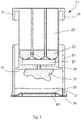
- Figur 3:
- einen Längsschnitt durch die Patrone aus
Figur 1 nach der Herstel-lung eines in additiven Schichten aufgebauten Gegenstandes. - In den
Figuren 1 und3 ist eine erste Ausführungsform einer 3D-Drucker-Einweg-Patrone gezeigt, welche gesamthaft mit dem Bezugszeichen 11 bezeichnet ist. - Die Patrone 11 umfasst ein erstes unteres Gehäuseteil 13 und ein zweites oberes Gehäuseteil 15. Bevor die Patrone 11 in eine Belichtungsvorrichtung (in den Figuren nicht gezeigt) eingesetzt wird, sind die beiden Gehäuseteile 13 und 15 voneinander zu trennen. Die Patrone 11 ist bis zu ihrer Verwendung in der Belichtungsvorrichtung hermetisch abgeschlossen und ist daher insbesondere für den Einsatz unter sterilen Bedingungen geeignet.
- Die beiden Gehäuseteile 13 und 15 sind an einer Sollbruchstelle 17 miteinander verbunden und lassen sich an dieser trennen, um die Patrone 11 gebrauchsfertig zu machen. Die Sollbruchstelle 17 lässt sich dadurch vorsehen, dass die Patrone 11 einstückig hergestellt ist. Bevorzugt wird die Patrone 11 im Spritzguss hergestellt. Sind das erste und das zweite Gehäuseteil 13 und 15 separat hergestellt, so werden sie lösbar miteinander verbunden, damit der Patroneninhalt abgedichtet ist. Wie die
Figuren 1 und 2 zeigen ist das untere Gehäuseteil 13 ein oben offener Behälter, in welchem das obere Gehäuseteil 15 aufgenommen ist. - Gemäss der ersten Ausführungsform der Patrone (
Figuren 1 und3 ) ist an dem zweiten oberen Gehäuseteil 15 eine Flüssigkeitskartusche 19a ausgebildet. In den Figuren ist eine Ausführungsform der Flüssigkeitskartusche 19a gezeigt, bei welcher drei unterschiedliche unter Belichtung polymerisierbare Flüssigkeiten 21a,21b,21c in den Aufnahmeräumen 23 der Flüssigkeitskartusche 19a abgefüllt sind. - Durch Stopfen 25 lassen sich die Flüssigkeiten 21a,21b,21c in eine Mischkammer 27 drücken in welcher diese durch Mischen aktivierbar sind. In der Mischkammer 27 kann ein statischer Mischer vorgesehen sein, welcher die Flüssigkeiten 21 homogen mischt. Durch einen Zulaufkanal 29 können die Flüssigkeiten 21a,21b,21b in das untere Gehäuseteil 13 eintreten. Das untere Gehäuseteil 13 kann daher als eine Wanne für das aktivierte Flüssigkeitsgemisch dienen.
- Die Unterseite des oberen Gehäuseteils 15 ist durch eine Trägerplattform 31 gebildet. An der Aussenseite der Trägerplattform 31, welche dem unteren Gehäuseteil 13 zugewandt ist, werden die Schichten des herzustellenden Gegenstandes 33 aufgebaut.
- Der Boden des unteren Gehäuseteils 13 ist als ein Aufbauelement 35 ausgeführt, an welchem die Schichten des Gegenstandes 33 polymerisierbar sind. Das Aufbauelement 35 oder wenigstens dessen innere Seite, welche dem zweiten Gehäuseteil 15 zugewandt ist, ist antihaftbeschichtet. Dadurch lassen sich die durch Belichtung polymerisierten Schichten von dem Aufbauelement 35 ablösen, wenn die jeweilige Schicht ausgehärtet ist.
- Als besonders vorteilhaft hat sich bei der Patrone 11 herausgestellt, dass diese sowohl die Trägerplattform 31 als auch das Aufbauelement 35 umfasst. Der Gegenstand 33 wird zwischen der Trägerplattform 31 und dem Aufbauelement in Schichten aufgebaut. Der Gegenstand wird daher innerhalb der Patrone 11 zwischen dem unteren Gehäuseteil 13 und dem oberen Gehäuseteil 15 nach dem sogenannten Bottom-Up-Verfahren hergestellt. Das heisst die aufzubauenden Objektschichten werden nicht an der Flüssigkeitsoberfläche (Harzoberfläche) sondern am Boden des unteren Gehäuseteils 13 aufgebaut. Da der Gegenstand aufgebaut wird, indem das obere Gehäuseteil 15 vom Boden des unteren Gehäuseteils 13 nach oben weg bewegt wird, ist es ausreichend, wenn eine geringe Menge gemischte Flüssigkeit (Harz) 37 in dem unteren Gehäuseteil 13 vorhanden ist. Der Boden bzw. das Aufbauelement 35 muss mit Harz bedeckt sein, damit das Harz zwischen Boden und Gegenstand 33 jederzeit nachfliesen kann, um eine Schicht aufzubauen. Die Lichtquelle ist unterhalb des Bodens angeordnet, weshalb der Boden bzw. das Aufbauelement 35 für das Licht durchgängig sein muss. Bevorzugt handelt es sich bei der Lichtquelle 35 um eine UV-Lichtquelle.
- Damit sich während der Herstellung des Gegenstandes 33 das obere Gehäuseteil 15 von dem unteren Gehäuseteil 13 weg bewegen lässt, lassen sich beide Gehäuseteile 13,15 in der Belichtungsvorrichtung befestigen. Dazu sind ein erstes Halteelement 39 an dem ersten unteren Gehäuseteil 13 und ein zweites Haltelement 41 an dem zweiten oberen Gehäuseteil 41 ausgebildet.
- Mit dem ersten Halteelement 39 lässt sich das untere Gehäuseteil 13 derart in der Belichtungsvorrichtung halten, dass das Aufbauelement 35 von der Lichtquelle 43 nach oben gedrückt wird und vorgespannt wird. Durch die Vorspannung des Aufbauelements 35 wird das Aufbauelement 35 relativ zu der Trägerplattform 31 ausgerichtet bzw. justiert. Die exakte Ausrichtung des Aufbauelements 35 ermöglicht es, dass der Gegenstand 33 mit sehr geringen Masstoleranzen herstellbar ist. Auch erleichtert die Vorspannung das Ablösen der jeweiligen ausgehärteten Schicht nach der LichtBestrahlung von dem Aufbauelement 35.
- Das Aufbauelement 35 umfasst bevorzugt eine Trennmembran. Die Trennmembran ist aus einem Antihaftmaterial aufgebaut, von welchem sich die ausgehärteten auspolymerisierten Gegenstandsschichten leicht lösen. Besonders bevorzugt ist es, wenn die Trennmembrane aus Perfluorethylenpropylen (FEP) besteht, da dieses Material bei vielen Licht-aushärtbaren Harzen antihaftend wirkt.
- Mit dem zweiten Haltelement 41 lässt sich das obere Gehäuseteil 15 an der Belichtungsvorrichtung befestigen. Die Belichtungsvorrichtung umfasst eine Hubvorrichtung, mit welcher das zweite Gehäuseteil 15 relativ zu dem ersten Gehäuseteil, bevorzugt stufenlos, angehoben werden kann und auch wieder abgesenkt werden kann. Jedes Mal, wenn eine Schicht des Gegenstandes 33 an der Lichtquelle durch Bestrahlung ausgehärtet worden ist, wird das obere Gehäuseteil 15 um die Dicke einer Schicht angehoben, nachdem der Gegenstand 33 von dem Aufbauelement 35 abgelöst wurde.
- Die Belichtungsvorrichtung umfasst auch wenigstens einen Stössel, mit welchem der Stopfen 25 nach unten gedrückt werden kann, um die Flüssigkeit 21a,21b,21c aus dem Aufnahmeraum 23 in das untere Gehäuseteil 13 ausdrücken zu können.
- Der Gegenstand lässt sich unter besonders hygienischen Bedingungen herstellen indem die Patrone 11 erst bei Herstellung des Gegenstandes 33 geöffnet wird, bereits mit der nötigen Menge an Flüssigkeiten 21a,21b,21c versetzt ist und der Gegenstand innerhalb der Patrone 11 hergestellt wird. Die Patrone 11 ist als Einweg-Patrone vorgesehen. Nach der Herstellung des Gegenstandes 33 und dessen Entnahme aus der Patrone 11, wird die Patrone 11 entsorgt.
- Die beiden Gehäuseteile 13,15 sind an ihren offenen Seiten jeweils mit einer ersten bzw. mit einer zweiten abziehbaren Schutzabdeckung 45,47 versehen. Dadurch ist die Patrone 11 bis zu ihrem Gebrauch hermetisch abgeschlossen. Vor Gebrauch sind die erste und die zweite Schutzabdeckung 45,47 zu entfernen. Die erste Schutzabdeckung 45 schützt das Aufbauelement 35 und die zweite Schutzabdeckung 47 schützt die Flüssigkeitskartusche 19a bzw. die Stopfen 25, damit diese nicht ungewollt vor Gebrauch verschoben oder verunreinigt werden.
- In der
Figur 2 ist eine zweite Ausführungsform der Patrone 11 gezeigt, bei welcher eine Flüssigkeitskartusche 19b nicht Teil des zweiten Gehäuseteils 15 ist, sondern ein separates Teil ist, welches in einen an dem zweiten Gehäuseteil 15 vorgesehenen Einsetzraum 49 eingesetzt werden kann. Dadurch lässt sich die Patrone 11 gemäss dieser zweiten Ausführungsform mit Flüssigkeitskartuschen nutzen, welche separat erhältlich sind. - Das Herstellen des Gegenstandes 33 mit der Patrone 11 erfolgt in den folgenden Verfahrensschritten: Zuerst wird die Patrone 11 geöffnet, indem die Sollbruchstelle 17 durch Drehen des oberen Gehäuseteils 15 relativ zum unteren Gehäuseteil 13 aufgebrochen wird. Dadurch werden die beiden Gehäuseteile 13,15, welche zuvor hermetisch dicht verbunden waren, voneinander getrennt. Die erste und die zweite Schutzabdeckung 45,47 werden von den Gehäuseteilen 13,15 entfernt, damit die Patrone 11 einsatzbereit ist.
- Beim Einsetzen der Patrone 11 in die Belichtungsvorrichtung bleibt das obere Gehäuseteil 15 weiterhin in dem unteren Gehäuseteil 13 aufgenommen und wird lediglich leicht angehoben. Die Trägerplattform 31 und das Aufbauelement 35 bleiben daher während dem Einsetzen der Patrone 11 weiterhin geschützt. Durch das Anheben lässt sich das obere Gehäuseteil 15 mit der Hubvorrichtung verbinden, indem das zweite Haltelement mit der Hubvorrichtung verbunden wird. Das unter Gehäuseteil 13 wird durch das erste Haltelement 39 mit der Belichtungsvorrichtung verbunden. Dabei wird das Aufbauelement 35 von der Lichtquelle 43 ausgerichtet.
- Nun werden die Flüssigkeiten 21a,21b,21c (lichthärtbare Harze) aus der Flüssigkeitskartusche 19a oder 19b mit Stösseln in das untere Gehäuseteil 13 ausgedrückt. Die Stössel sind an der Belichtungsvorrichtung vorgesehen und lassen sich an die Anzahl der Aufnahmeräume 23 und den notwendigen Verschiebeweg der Stopfen 25 anpassen.
- Wenn die gemischten Flüssigkeiten 37 das Aufbauelement 35 bedecken, wird mit dem additiven Aufbau der Schichten des Gegenstandes 33 begonnen. Nach Aushärten einer Schicht durch Bestrahlung mit der Lichtquelle 43 wird das obere Gehäuseteil 15 mit der Hubvorrichtung um eine Schichtdicke aus dem unteren Gehäuseteil 13 angehoben. Der Abstand zwischen den beiden Gehäuseteilen 13,15 wird daher während dem Aufbau des Gegenstandes vergrössert.
- Denkbar ist es auch, dass die Flüssigkeitskartusche 19a oder 19b synchronisiert mit dem Schichtaufbau und nicht vor dem Schichtaufbau entleert wird. Dies kann dann Sinn machen, wenn die Flüssigkeiten nur sehr kurz vor der Verarbeitung gemischt werden sollen.
- Die 3D-Drucker-Einweg-Patrone 11 weist einen sehr hohen hygienischen Standard auf, da sie erst kurz vor der Herstellung des Gegenstandes 33 geöffnet wird und zuvor hermetisch abgeschlossen ist. Zudem enthält sie nur die Menge an aushärtbaren Flüssigkeiten 21a,21b,21c, welche für die Herstellung des Gegenstandes 33 benötigt wird. Die Patrone 11 wird nach Herstellung des Gegenstandes 33 entsorgt, wodurch keine weitere Reinigung notwendig ist. Zur Herstellung des Gegenstandes 33 wird daher immer eine neue hygienisch einwandfreie Patrone 11 verwendet.
- Legende:
- 11
- 3D-Drucker-Einweg-Patrone
- 13
- Erstes unteres Gehäuseteil
- 15
- Zweites oberes Gehäuseteil
- 17
- Sollbruchstelle
- 19a,19b
- Flüssigkeitskartusche
- 21a,21b,21c
- polymerisierbare Flüssigkeiten
- 23
- Aufnahmeräume
- 25
- Stopfen
- 27
- Mischkammer
- 29
- Zulaufkanal
- 31
- Trägerplattform
- 33
- In additiven Schichten aufgebauter Gegenstand
- 35
- Aufbauelement
- 37
- Gemischte Flüssigkeit
- 39
- erstes Halteelement
- 41
- zweites Halteelement
- 43
- Lichtquelle
- 45
- Erste Schutzabdeckung
- 47
- Zweite Schutzabdeckung
- 49
- Einsetzraum
Claims (15)
- 3D-Drucker-Einweg-Patrone (11) zum Einsetzen in eine Belichtungsvorrichtung zur Produktion eines in additiven Schichten aufgebauten Gegenstandes (33), welche Patrone (11) wenigstens eine polymerisierbare Flüssigkeit (21a,21b,21c) enthält oder in welche Patrone (11) eine polymerisierbare Flüssigkeit einfüllbar ist, die Patrone (11) umfassend- ein erstes unteres Gehäuseteil (13),- ein zweites oberes Gehäuseteil (15), welches das erste Gehäuseteil (13) verschliesst,- eine Trägerplattform (31), welche die Unterseite des zweiten Gehäuseteils (15) bildet, wobei an der Aussenseite der Trägerplattform der in additiven Schichten hergestellte Gegenstand (33) während dessen Aufbau anordenbar ist und- ein Aufbauelement (35), welches dem Boden des ersten Gehäuseteils (13) entspricht, wobei an der inneren Seite des Aufbauelements (35) die Schichten des Gegenstandes (33) polymerisierbar sind und die innere Seite des Aufbauelements (35) antihaftbeschichtet ist,dadurch gekennzeichnet,dass zur Öffnung der Patrone zur Produktion des Gegenstandes (33) das obere Gehäuseteil (15) von dem unteren Gehäuseteil (13) trennbar ist unddass das erste Gehäuseteil (13) ein oben offener Behälter ist, in welchem das zweite Gehäuseteil (15) aufgenommen ist.
- Patrone nach Anspruch 1, dadurch gekennzeichnet, dass an dem zweiten Gehäuseteil (15) eine Flüssigkeitskartusche (19a) ausgebildet ist, welche mit der wenigstens einen polymerisierbaren Flüssigkeit (21a,21b,21c) gefüllt ist.
- Patrone nach einem der Ansprüche 1 oder 2, dadurch gekennzeichnet, dass an dem zweiten Gehäuseteil (15) ein Einsetzraum (49) vorgesehen ist, in welchen Einsatzraum (49) eine Flüssigkeitskartusche (19b) einsetzbar ist.
- Patrone nach einem der Ansprüche 2 oder 3, dadurch gekennzeichnet, dass die Flüssigkeitskartusche (19a) wenigstens einen ersten und einen zweiten Aufnahmeraum (23) aufweist, in welche eine erste und eine zweite polymerisierbaren Flüssigkeit (21a,21b) abgefüllt sind, wobei die unteren Enden der Aufnahmeräume in eine Mischkammer (27) münden und die Trägerplattform (31) von wenigstens einem mit der Mischkammer (27) in Fluidverbindung stehenden Zulaufkanal (29) unterbrochen ist, welcher Zulaufkanal (29) in das erste untere Gehäuseteil (13) mündet, wodurch das Flüssigkeitsgemisch (37) in das untere Gehäuseteil (15) überführbar ist.
- Patrone nach einem der vorangehenden Ansprüche, dadurch gekennzeichnet, dass die Patrone (15) einteilig ausgebildet ist und am Übergang vom ersten Gehäuseteil (13) zum zweiten Gehäuseteil (15) eine Sollbruchstelle (17) aufweist.
- Patrone nach einem der Ansprüche 1 bis 4, dadurch gekennzeichnet, dass die Patrone (11) zweiteilig ausgebildet ist und das erste und das zweite Gehäuseteil (13,15) lösbar miteinander verbunden sind.
- Patrone nach einem der vorangehenden Ansprüche, dadurch gekennzeichnet, dass das erste und das zweite Gehäuseteil (13,15) mit einem dehnbaren Verbindungselement im Bereich des Übergangs vom ersten Gehäuseteil (13) zum zweiten Gehäuseteil (15) verbunden sind.
- Patrone nach einem der vorangehenden Ansprüche, dadurch gekennzeichnet, dass die Aussenseite des Bodens des ersten Gehäuseteils (13) mit einer ersten abziehbaren Schutzabdeckung (45) abgedeckt ist.
- Patrone nach einem der vorangehenden Ansprüche, dadurch gekennzeichnet, dass die Oberseite des zweiten Gehäuseteils (15) mit einer zweiten abziehbaren Schutzabdeckung(47) abgedeckt ist.
- Patrone nach einem der vorangehenden Ansprüche, dadurch gekennzeichnet, dass die Flüssigkeitskartusche (19a,19b) wenigstens einen Stopfen (25) aufweist, welcher das Ausdrücken der Flüssigkeit (21a,21b21c) ermöglicht und die Einfüllöffnung der Flüssigkeitskartusche (19a,19b) verschliesst.
- Patrone nach einem der vorangehenden Ansprüche, dadurch gekennzeichnet, dass das erste Gehäuseteil (13) ein erstes Halteelement (39) aufweist, mit welchem es an der Belichtungsvorrichtung gehalten werden kann und welches erste Halteelement (39) es ermöglicht, dass das Aufbauelement (35) an der Belichtungsvorrichtung gespannt werden kann.
- Patrone nach einem der vorangehenden Ansprüche, dadurch gekennzeichnet, dass das zweite Gehäuseteil (15) ein zweites Halteelement (41) aufweist, mit welchem es an der Belichtungsvorrichtung gehalten werden kann.
- System aus einer 3D-Drucker-Einweg-Patrone (11) gemäss einem der vorangehenden Ansprüche und einer Belichtungsvorrichtung, in welche das erste und das zweite Gehäuseteil (13,15) einsetzbar sind, wobei der in additiven Schichten aufgebaute Gegenstand (33) zwischen dem ersten und dem zweiten Gehäuseteil (13,15) an der Trägerplattform (31) herstellbar ist.
- Verfahren zur Herstellung eines aus additiven Schichten bestehenden Gegenstandes (33), die folgenden Verfahrensschritte aufweisend:- Öffnen einer 3D-Drucker-Einweg-Patrone (11) gemäss einem der Patentansprüche 1 bis 12, indem das untere erste Gehäuseteil (13) von dem zweiten oberen Gehäuseteil (15) getrennt wird,- Befestigen des ersten und des zweiten Gehäuseteils (13,15) in der Belichtungsvorrichtung,- Ausdrücken der wenigstens einen polymerisierbaren Flüssigkeit (21a,21b,21c) aus dem zweiten Gehäuseteil (15) in das erste Gehäuseteil (13) mithilfe von wenigstens einem an der Belichtungsvorrichtung vorgesehenen Stössel und- stufenweiser Aufbau der additiven Schichten des Gegenstandes (33), indem der Abstand zwischen dem ersten und dem zweiten Gehäuseteil (13,15) jeweils nach Aushärten einer Schicht durch Belichtung stufenweise vergrössert wird.
- Verfahren nach Anspruch 14, dadurch gekennzeichnet, dass das Ausdrücken der wenigstens einen polymerisierbaren Flüssigkeit (21a,21b,21c) vollständig vor dem Aufbau des Gegenstandes (33) erfolgt oder synchronisiert während des Aufbaus der Schichten des Gegenstandes (33) erfolgt.
Applications Claiming Priority (2)
| Application Number | Priority Date | Filing Date | Title |
|---|---|---|---|
| CH00278/18A CH714727B1 (de) | 2018-03-07 | 2018-03-07 | 3D-Drucker-Einweg-Patrone. |
| PCT/CH2019/050003 WO2019169511A1 (de) | 2018-03-07 | 2019-03-06 | 3d-drucker-einweg-patrone |
Publications (2)
| Publication Number | Publication Date |
|---|---|
| EP3762212A1 EP3762212A1 (de) | 2021-01-13 |
| EP3762212B1 true EP3762212B1 (de) | 2022-04-27 |
Family
ID=62104053
Family Applications (1)
| Application Number | Title | Priority Date | Filing Date |
|---|---|---|---|
| EP19710585.1A Active EP3762212B1 (de) | 2018-03-07 | 2019-03-06 | 3d-drucker-einweg-patrone |
Country Status (14)
| Country | Link |
|---|---|
| US (1) | US11801634B2 (de) |
| EP (1) | EP3762212B1 (de) |
| JP (1) | JP7284183B2 (de) |
| KR (1) | KR102776817B1 (de) |
| CN (1) | CN111902257A (de) |
| AU (1) | AU2019231373A1 (de) |
| BR (1) | BR112020018038B1 (de) |
| CA (1) | CA3092407A1 (de) |
| CH (1) | CH714727B1 (de) |
| ES (1) | ES2924033T3 (de) |
| MX (1) | MX2020008915A (de) |
| RU (1) | RU2020132269A (de) |
| TW (1) | TWI813639B (de) |
| WO (1) | WO2019169511A1 (de) |
Families Citing this family (6)
| Publication number | Priority date | Publication date | Assignee | Title |
|---|---|---|---|---|
| DE102020123753A1 (de) * | 2020-09-11 | 2022-03-17 | Deutsches Zentrum für Luft- und Raumfahrt e.V. | Vorrichtung und Verfahren zur additiven Fertigung von Bauteilen in Umgebungen mit unterschiedlicher Gravitation und mit Material unterschiedlicher Fließfähigkeit |
| IL288719B2 (en) * | 2021-12-06 | 2025-06-01 | Kenig Edan | A sterile contact lens 3d printing method and device |
| US20250345998A1 (en) * | 2022-04-11 | 2025-11-13 | Sprintray, Inc. | Single-use cartridge with built-in reservoir and build plate for additive manufacturing devices |
| US12128624B2 (en) * | 2022-12-16 | 2024-10-29 | Sprintray, Inc. | Hydraulic 3D-printing system and method |
| WO2025111573A1 (en) * | 2023-11-22 | 2025-05-30 | Quadratic 3D, Inc. | Cartridge for 3d printing in a volume and methods and systems including same |
| WO2025136836A1 (en) * | 2023-12-18 | 2025-06-26 | Sprintray, Inc. | Hydraulic 3d-printing system and method |
Family Cites Families (13)
| Publication number | Priority date | Publication date | Assignee | Title |
|---|---|---|---|---|
| US5738921A (en) * | 1993-08-10 | 1998-04-14 | E. Khashoggi Industries, Llc | Compositions and methods for manufacturing sealable, liquid-tight containers comprising an inorganically filled matrix |
| JP2002178496A (ja) * | 2000-12-14 | 2002-06-26 | Canon Inc | 3次元記録装置及び3次元記録方法 |
| US9723866B2 (en) * | 2004-08-11 | 2017-08-08 | Cornell University | System and method for solid freeform fabrication of edible food |
| US7931460B2 (en) * | 2006-05-03 | 2011-04-26 | 3D Systems, Inc. | Material delivery system for use in solid imaging |
| US8298637B2 (en) * | 2008-08-07 | 2012-10-30 | Trodat Gmbh | Photopolymer assembly |
| US9884318B2 (en) * | 2012-02-10 | 2018-02-06 | Adam Perry Tow | Multi-axis, multi-purpose robotics automation and quality adaptive additive manufacturing |
| JP2015089649A (ja) * | 2013-11-06 | 2015-05-11 | 株式会社リコー | 交換ユニット、交換ユニット保持装置及び画像形成装置 |
| EP3209485B1 (de) * | 2014-10-24 | 2021-04-07 | Xeikon Prepress NV | Stereolithographieverfahren und -vorrichtung und halter zur verwendung in solch einem verfahren |
| CA3105809C (en) * | 2015-11-12 | 2023-06-13 | Klaus Stadlmann | Stereolithography device comprising cartridge unit |
| CN109640873B (zh) * | 2016-08-03 | 2021-09-07 | 3M创新有限公司 | 用于由可光硬化材料逐渐构建物体的装置和方法 |
| IT201700015055A1 (it) * | 2017-02-10 | 2018-08-10 | Dws Srl | Cartuccia perfezionata per l’alimentazione di una macchina stereolitografica e macchina stereolitografica impiegante tale cartuccia |
| CN206983271U (zh) * | 2017-06-26 | 2018-02-09 | 比亚迪股份有限公司 | 一种3d打印装置 |
| SG11202002255TA (en) * | 2017-09-26 | 2020-04-29 | Memjet Technology Ltd | Print engine for color digital inkjet press |
-
2018
- 2018-03-07 CH CH00278/18A patent/CH714727B1/de not_active IP Right Cessation
-
2019
- 2019-03-06 JP JP2020546484A patent/JP7284183B2/ja active Active
- 2019-03-06 AU AU2019231373A patent/AU2019231373A1/en not_active Abandoned
- 2019-03-06 BR BR112020018038-6A patent/BR112020018038B1/pt not_active IP Right Cessation
- 2019-03-06 ES ES19710585T patent/ES2924033T3/es active Active
- 2019-03-06 EP EP19710585.1A patent/EP3762212B1/de active Active
- 2019-03-06 MX MX2020008915A patent/MX2020008915A/es unknown
- 2019-03-06 WO PCT/CH2019/050003 patent/WO2019169511A1/de not_active Ceased
- 2019-03-06 KR KR1020207028665A patent/KR102776817B1/ko active Active
- 2019-03-06 RU RU2020132269A patent/RU2020132269A/ru unknown
- 2019-03-06 CA CA3092407A patent/CA3092407A1/en active Pending
- 2019-03-06 CN CN201980017749.8A patent/CN111902257A/zh active Pending
- 2019-03-06 US US16/979,140 patent/US11801634B2/en active Active
- 2019-03-07 TW TW108107631A patent/TWI813639B/zh active
Also Published As
| Publication number | Publication date |
|---|---|
| RU2020132269A (ru) | 2022-04-07 |
| US11801634B2 (en) | 2023-10-31 |
| WO2019169511A1 (de) | 2019-09-12 |
| TW201940310A (zh) | 2019-10-16 |
| MX2020008915A (es) | 2020-12-11 |
| EP3762212A1 (de) | 2021-01-13 |
| US20200398490A1 (en) | 2020-12-24 |
| BR112020018038A2 (pt) | 2020-12-22 |
| TWI813639B (zh) | 2023-09-01 |
| JP7284183B2 (ja) | 2023-05-30 |
| AU2019231373A1 (en) | 2020-09-24 |
| CH714727B1 (de) | 2022-07-15 |
| KR102776817B1 (ko) | 2025-03-10 |
| ES2924033T3 (es) | 2022-10-04 |
| CN111902257A (zh) | 2020-11-06 |
| BR112020018038B1 (pt) | 2024-01-23 |
| KR20210008330A (ko) | 2021-01-21 |
| CA3092407A1 (en) | 2019-09-12 |
| JP2021517082A (ja) | 2021-07-15 |
| CH714727A1 (de) | 2019-09-13 |
Similar Documents
| Publication | Publication Date | Title |
|---|---|---|
| EP3762212B1 (de) | 3d-drucker-einweg-patrone | |
| DE69022047T2 (de) | Anordnung zur herstellung von knochenzement. | |
| EP3374160B1 (de) | Stereolithographie-vorrichtung mit kartuscheneinrichtung | |
| EP2823881B1 (de) | Vorrichtung und Verfahren zum Lagern und Mischen von Knochenzement | |
| DE60018003T2 (de) | Hilfswerkzeug zum Auspressen eines chemischen Wirkstoffes und Verfahren zur Verwendung desselben | |
| EP1344500B1 (de) | Mehrkomponenten-Mischkapsel, insbesondere für Dentalzwecke | |
| EP2883603B1 (de) | Vorrichtung zum Lagern und Mischen von Knochenzement | |
| EP0261182A1 (de) | VORRICHTUNG UND VERFAHREN ZUM UMFÜLLEN EINES VISKöSEN STOFFGEMISCHES, INSBESONDERE VON KNOCHENZEMENT. | |
| DE102014101305A1 (de) | Vorrichtung zum Lagern und Mischen von Knochenzement | |
| EP0663348A1 (de) | Vorrichtung zum Entleeren eines Schlauchbeutels | |
| DE2060626B2 (de) | Mischbehaelter fuer die aufnahme von miteinander reagierenden substanzen fuer die herstellung von gebrauchsfertigen dentalpraeparaten | |
| DE102011007475A1 (de) | Folienkartusche und Verfahren zur Herstellung einer Folienkartusche | |
| DE102021109816A1 (de) | Verfahren zum Entleeren von viskosem Material aus einer beidseitig offenen Kartusche sowie hierfür geeignete Entleer-Vorrichtung | |
| DE2302364C3 (de) | Als Ausdrückkolben für plastische Masse dienender Verschluß aus elastischem Werkstoff für einen hohlzylindrischen Strangpreßbehälter | |
| DE3823708C2 (de) | Motorisch angetriebene Einrichtung zum Dosieren und Mischen von wenigstens zwei Substanzen | |
| EP1002718B1 (de) | Füllvorrichtung für Kartuschen | |
| DE3536320C2 (de) | ||
| EP4474042A1 (de) | Mischsystem mit seitlichem ampullenbrecher | |
| EP0039693A1 (de) | Vorrichtung zur aufnahme von komponenten für eine mischung oder verbindung in mindestens zwei getrennten behältern | |
| EP1029513B1 (de) | Misch- und Applikationskapsel | |
| DE4022985A1 (de) | Vorrichtung zur aufnahme von knochenzement | |
| DE2400970C2 (de) | Mischbehälter für die Aufnahme von miteinander reagierenden Substanzen für die Herstellung von gebrauchsfertigen Dentalpräparaten | |
| WO2019052836A1 (de) | Nahrungsmittel-kartusche mit einem integrierten mischelement | |
| EP4385613A1 (de) | Vorrichtung zum mischen von knochenzement | |
| EP0191727B1 (de) | Verfahren und Vorrichtung zur Bearbeitung von Zahnabdruckmaterial |
Legal Events
| Date | Code | Title | Description |
|---|---|---|---|
| STAA | Information on the status of an ep patent application or granted ep patent |
Free format text: STATUS: UNKNOWN |
|
| STAA | Information on the status of an ep patent application or granted ep patent |
Free format text: STATUS: THE INTERNATIONAL PUBLICATION HAS BEEN MADE |
|
| PUAI | Public reference made under article 153(3) epc to a published international application that has entered the european phase |
Free format text: ORIGINAL CODE: 0009012 |
|
| STAA | Information on the status of an ep patent application or granted ep patent |
Free format text: STATUS: REQUEST FOR EXAMINATION WAS MADE |
|
| 17P | Request for examination filed |
Effective date: 20201006 |
|
| AK | Designated contracting states |
Kind code of ref document: A1 Designated state(s): AL AT BE BG CH CY CZ DE DK EE ES FI FR GB GR HR HU IE IS IT LI LT LU LV MC MK MT NL NO PL PT RO RS SE SI SK SM TR |
|
| AX | Request for extension of the european patent |
Extension state: BA ME |
|
| DAV | Request for validation of the european patent (deleted) | ||
| DAX | Request for extension of the european patent (deleted) | ||
| GRAP | Despatch of communication of intention to grant a patent |
Free format text: ORIGINAL CODE: EPIDOSNIGR1 |
|
| STAA | Information on the status of an ep patent application or granted ep patent |
Free format text: STATUS: GRANT OF PATENT IS INTENDED |
|
| INTG | Intention to grant announced |
Effective date: 20210923 |
|
| RAP1 | Party data changed (applicant data changed or rights of an application transferred) |
Owner name: SCHMID, DIETER Owner name: SCHMID, MARCO |
|
| RIN1 | Information on inventor provided before grant (corrected) |
Inventor name: SCHMID, DIETER Inventor name: SCHMID, MARCO |
|
| GRAS | Grant fee paid |
Free format text: ORIGINAL CODE: EPIDOSNIGR3 |
|
| GRAA | (expected) grant |
Free format text: ORIGINAL CODE: 0009210 |
|
| STAA | Information on the status of an ep patent application or granted ep patent |
Free format text: STATUS: THE PATENT HAS BEEN GRANTED |
|
| AK | Designated contracting states |
Kind code of ref document: B1 Designated state(s): AL AT BE BG CH CY CZ DE DK EE ES FI FR GB GR HR HU IE IS IT LI LT LU LV MC MK MT NL NO PL PT RO RS SE SI SK SM TR |
|
| REG | Reference to a national code |
Ref country code: GB Ref legal event code: FG4D Free format text: NOT ENGLISH |
|
| REG | Reference to a national code |
Ref country code: CH Ref legal event code: EP |
|
| REG | Reference to a national code |
Ref country code: AT Ref legal event code: REF Ref document number: 1486609 Country of ref document: AT Kind code of ref document: T Effective date: 20220515 |
|
| REG | Reference to a national code |
Ref country code: DE Ref legal event code: R096 Ref document number: 502019004199 Country of ref document: DE |
|
| REG | Reference to a national code |
Ref country code: IE Ref legal event code: FG4D Free format text: LANGUAGE OF EP DOCUMENT: GERMAN |
|
| REG | Reference to a national code |
Ref country code: LT Ref legal event code: MG9D |
|
| REG | Reference to a national code |
Ref country code: NL Ref legal event code: MP Effective date: 20220427 |
|
| PG25 | Lapsed in a contracting state [announced via postgrant information from national office to epo] |
Ref country code: NL Free format text: LAPSE BECAUSE OF FAILURE TO SUBMIT A TRANSLATION OF THE DESCRIPTION OR TO PAY THE FEE WITHIN THE PRESCRIBED TIME-LIMIT Effective date: 20220427 |
|
| REG | Reference to a national code |
Ref country code: ES Ref legal event code: FG2A Ref document number: 2924033 Country of ref document: ES Kind code of ref document: T3 Effective date: 20221004 |
|
| PG25 | Lapsed in a contracting state [announced via postgrant information from national office to epo] |
Ref country code: SE Free format text: LAPSE BECAUSE OF FAILURE TO SUBMIT A TRANSLATION OF THE DESCRIPTION OR TO PAY THE FEE WITHIN THE PRESCRIBED TIME-LIMIT Effective date: 20220427 Ref country code: PT Free format text: LAPSE BECAUSE OF FAILURE TO SUBMIT A TRANSLATION OF THE DESCRIPTION OR TO PAY THE FEE WITHIN THE PRESCRIBED TIME-LIMIT Effective date: 20220829 Ref country code: NO Free format text: LAPSE BECAUSE OF FAILURE TO SUBMIT A TRANSLATION OF THE DESCRIPTION OR TO PAY THE FEE WITHIN THE PRESCRIBED TIME-LIMIT Effective date: 20220727 Ref country code: LT Free format text: LAPSE BECAUSE OF FAILURE TO SUBMIT A TRANSLATION OF THE DESCRIPTION OR TO PAY THE FEE WITHIN THE PRESCRIBED TIME-LIMIT Effective date: 20220427 Ref country code: HR Free format text: LAPSE BECAUSE OF FAILURE TO SUBMIT A TRANSLATION OF THE DESCRIPTION OR TO PAY THE FEE WITHIN THE PRESCRIBED TIME-LIMIT Effective date: 20220427 Ref country code: GR Free format text: LAPSE BECAUSE OF FAILURE TO SUBMIT A TRANSLATION OF THE DESCRIPTION OR TO PAY THE FEE WITHIN THE PRESCRIBED TIME-LIMIT Effective date: 20220728 Ref country code: FI Free format text: LAPSE BECAUSE OF FAILURE TO SUBMIT A TRANSLATION OF THE DESCRIPTION OR TO PAY THE FEE WITHIN THE PRESCRIBED TIME-LIMIT Effective date: 20220427 Ref country code: BG Free format text: LAPSE BECAUSE OF FAILURE TO SUBMIT A TRANSLATION OF THE DESCRIPTION OR TO PAY THE FEE WITHIN THE PRESCRIBED TIME-LIMIT Effective date: 20220727 |
|
| PG25 | Lapsed in a contracting state [announced via postgrant information from national office to epo] |
Ref country code: RS Free format text: LAPSE BECAUSE OF FAILURE TO SUBMIT A TRANSLATION OF THE DESCRIPTION OR TO PAY THE FEE WITHIN THE PRESCRIBED TIME-LIMIT Effective date: 20220427 Ref country code: PL Free format text: LAPSE BECAUSE OF FAILURE TO SUBMIT A TRANSLATION OF THE DESCRIPTION OR TO PAY THE FEE WITHIN THE PRESCRIBED TIME-LIMIT Effective date: 20220427 Ref country code: LV Free format text: LAPSE BECAUSE OF FAILURE TO SUBMIT A TRANSLATION OF THE DESCRIPTION OR TO PAY THE FEE WITHIN THE PRESCRIBED TIME-LIMIT Effective date: 20220427 Ref country code: IS Free format text: LAPSE BECAUSE OF FAILURE TO SUBMIT A TRANSLATION OF THE DESCRIPTION OR TO PAY THE FEE WITHIN THE PRESCRIBED TIME-LIMIT Effective date: 20220827 |
|
| REG | Reference to a national code |
Ref country code: DE Ref legal event code: R097 Ref document number: 502019004199 Country of ref document: DE |
|
| PG25 | Lapsed in a contracting state [announced via postgrant information from national office to epo] |
Ref country code: SM Free format text: LAPSE BECAUSE OF FAILURE TO SUBMIT A TRANSLATION OF THE DESCRIPTION OR TO PAY THE FEE WITHIN THE PRESCRIBED TIME-LIMIT Effective date: 20220427 Ref country code: SK Free format text: LAPSE BECAUSE OF FAILURE TO SUBMIT A TRANSLATION OF THE DESCRIPTION OR TO PAY THE FEE WITHIN THE PRESCRIBED TIME-LIMIT Effective date: 20220427 Ref country code: RO Free format text: LAPSE BECAUSE OF FAILURE TO SUBMIT A TRANSLATION OF THE DESCRIPTION OR TO PAY THE FEE WITHIN THE PRESCRIBED TIME-LIMIT Effective date: 20220427 Ref country code: EE Free format text: LAPSE BECAUSE OF FAILURE TO SUBMIT A TRANSLATION OF THE DESCRIPTION OR TO PAY THE FEE WITHIN THE PRESCRIBED TIME-LIMIT Effective date: 20220427 Ref country code: DK Free format text: LAPSE BECAUSE OF FAILURE TO SUBMIT A TRANSLATION OF THE DESCRIPTION OR TO PAY THE FEE WITHIN THE PRESCRIBED TIME-LIMIT Effective date: 20220427 Ref country code: CZ Free format text: LAPSE BECAUSE OF FAILURE TO SUBMIT A TRANSLATION OF THE DESCRIPTION OR TO PAY THE FEE WITHIN THE PRESCRIBED TIME-LIMIT Effective date: 20220427 |
|
| PLBE | No opposition filed within time limit |
Free format text: ORIGINAL CODE: 0009261 |
|
| STAA | Information on the status of an ep patent application or granted ep patent |
Free format text: STATUS: NO OPPOSITION FILED WITHIN TIME LIMIT |
|
| PG25 | Lapsed in a contracting state [announced via postgrant information from national office to epo] |
Ref country code: AL Free format text: LAPSE BECAUSE OF FAILURE TO SUBMIT A TRANSLATION OF THE DESCRIPTION OR TO PAY THE FEE WITHIN THE PRESCRIBED TIME-LIMIT Effective date: 20220427 |
|
| 26N | No opposition filed |
Effective date: 20230130 |
|
| PG25 | Lapsed in a contracting state [announced via postgrant information from national office to epo] |
Ref country code: SI Free format text: LAPSE BECAUSE OF FAILURE TO SUBMIT A TRANSLATION OF THE DESCRIPTION OR TO PAY THE FEE WITHIN THE PRESCRIBED TIME-LIMIT Effective date: 20220427 |
|
| PG25 | Lapsed in a contracting state [announced via postgrant information from national office to epo] |
Ref country code: MC Free format text: LAPSE BECAUSE OF FAILURE TO SUBMIT A TRANSLATION OF THE DESCRIPTION OR TO PAY THE FEE WITHIN THE PRESCRIBED TIME-LIMIT Effective date: 20220427 |
|
| PG25 | Lapsed in a contracting state [announced via postgrant information from national office to epo] |
Ref country code: LU Free format text: LAPSE BECAUSE OF NON-PAYMENT OF DUE FEES Effective date: 20230306 |
|
| PGFP | Annual fee paid to national office [announced via postgrant information from national office to epo] |
Ref country code: IE Payment date: 20240927 Year of fee payment: 6 |
|
| PGFP | Annual fee paid to national office [announced via postgrant information from national office to epo] |
Ref country code: GB Payment date: 20240927 Year of fee payment: 6 |
|
| PGFP | Annual fee paid to national office [announced via postgrant information from national office to epo] |
Ref country code: BE Payment date: 20240927 Year of fee payment: 6 |
|
| PGFP | Annual fee paid to national office [announced via postgrant information from national office to epo] |
Ref country code: FR Payment date: 20240927 Year of fee payment: 6 |
|
| PGFP | Annual fee paid to national office [announced via postgrant information from national office to epo] |
Ref country code: ES Payment date: 20240926 Year of fee payment: 6 |
|
| PG25 | Lapsed in a contracting state [announced via postgrant information from national office to epo] |
Ref country code: BG Free format text: LAPSE BECAUSE OF FAILURE TO SUBMIT A TRANSLATION OF THE DESCRIPTION OR TO PAY THE FEE WITHIN THE PRESCRIBED TIME-LIMIT Effective date: 20220427 |
|
| PG25 | Lapsed in a contracting state [announced via postgrant information from national office to epo] |
Ref country code: BG Free format text: LAPSE BECAUSE OF FAILURE TO SUBMIT A TRANSLATION OF THE DESCRIPTION OR TO PAY THE FEE WITHIN THE PRESCRIBED TIME-LIMIT Effective date: 20220427 |
|
| PG25 | Lapsed in a contracting state [announced via postgrant information from national office to epo] |
Ref country code: CY Free format text: LAPSE BECAUSE OF FAILURE TO SUBMIT A TRANSLATION OF THE DESCRIPTION OR TO PAY THE FEE WITHIN THE PRESCRIBED TIME-LIMIT; INVALID AB INITIO Effective date: 20190306 |
|
| PG25 | Lapsed in a contracting state [announced via postgrant information from national office to epo] |
Ref country code: HU Free format text: LAPSE BECAUSE OF FAILURE TO SUBMIT A TRANSLATION OF THE DESCRIPTION OR TO PAY THE FEE WITHIN THE PRESCRIBED TIME-LIMIT; INVALID AB INITIO Effective date: 20190306 |
|
| PGFP | Annual fee paid to national office [announced via postgrant information from national office to epo] |
Ref country code: IT Payment date: 20250929 Year of fee payment: 7 |
|
| PGFP | Annual fee paid to national office [announced via postgrant information from national office to epo] |
Ref country code: AT Payment date: 20250930 Year of fee payment: 7 |
|
| PGFP | Annual fee paid to national office [announced via postgrant information from national office to epo] |
Ref country code: CH Payment date: 20250924 Year of fee payment: 7 |
|
| GBPC | Gb: european patent ceased through non-payment of renewal fee |
Effective date: 20250306 |
|
| PG25 | Lapsed in a contracting state [announced via postgrant information from national office to epo] |
Ref country code: TR Free format text: LAPSE BECAUSE OF FAILURE TO SUBMIT A TRANSLATION OF THE DESCRIPTION OR TO PAY THE FEE WITHIN THE PRESCRIBED TIME-LIMIT Effective date: 20220427 |
|
| REG | Reference to a national code |
Ref country code: BE Ref legal event code: MM Effective date: 20250331 |
|
| PGFP | Annual fee paid to national office [announced via postgrant information from national office to epo] |
Ref country code: DE Payment date: 20250929 Year of fee payment: 7 |
|
| PG25 | Lapsed in a contracting state [announced via postgrant information from national office to epo] |
Ref country code: GB Free format text: LAPSE BECAUSE OF NON-PAYMENT OF DUE FEES Effective date: 20250306 |
|
| PG25 | Lapsed in a contracting state [announced via postgrant information from national office to epo] |
Ref country code: FR Free format text: LAPSE BECAUSE OF NON-PAYMENT OF DUE FEES Effective date: 20250331 |
|
| PG25 | Lapsed in a contracting state [announced via postgrant information from national office to epo] |
Ref country code: BE Free format text: LAPSE BECAUSE OF NON-PAYMENT OF DUE FEES Effective date: 20250331 |
|
| PG25 | Lapsed in a contracting state [announced via postgrant information from national office to epo] |
Ref country code: IE Free format text: LAPSE BECAUSE OF NON-PAYMENT OF DUE FEES Effective date: 20250306 |