EP3762275B1 - Systèmes de direction hydraulique pour roues de véhicule - Google Patents
Systèmes de direction hydraulique pour roues de véhicule Download PDFInfo
- Publication number
- EP3762275B1 EP3762275B1 EP19701325.3A EP19701325A EP3762275B1 EP 3762275 B1 EP3762275 B1 EP 3762275B1 EP 19701325 A EP19701325 A EP 19701325A EP 3762275 B1 EP3762275 B1 EP 3762275B1
- Authority
- EP
- European Patent Office
- Prior art keywords
- cylinder
- vehicle
- steering
- wheel
- steering system
- Prior art date
- Legal status (The legal status is an assumption and is not a legal conclusion. Google has not performed a legal analysis and makes no representation as to the accuracy of the status listed.)
- Active
Links
Images

Classifications
-
- B—PERFORMING OPERATIONS; TRANSPORTING
- B62—LAND VEHICLES FOR TRAVELLING OTHERWISE THAN ON RAILS
- B62D—MOTOR VEHICLES; TRAILERS
- B62D5/00—Power-assisted or power-driven steering
- B62D5/06—Power-assisted or power-driven steering fluid, i.e. using a pressurised fluid for most or all the force required for steering a vehicle
- B62D5/10—Power-assisted or power-driven steering fluid, i.e. using a pressurised fluid for most or all the force required for steering a vehicle characterised by type of power unit
- B62D5/12—Piston and cylinder
-
- B—PERFORMING OPERATIONS; TRANSPORTING
- B62—LAND VEHICLES FOR TRAVELLING OTHERWISE THAN ON RAILS
- B62D—MOTOR VEHICLES; TRAILERS
- B62D5/00—Power-assisted or power-driven steering
- B62D5/06—Power-assisted or power-driven steering fluid, i.e. using a pressurised fluid for most or all the force required for steering a vehicle
- B62D5/20—Power-assisted or power-driven steering fluid, i.e. using a pressurised fluid for most or all the force required for steering a vehicle specially adapted for particular type of steering gear or particular application
- B62D5/26—Power-assisted or power-driven steering fluid, i.e. using a pressurised fluid for most or all the force required for steering a vehicle specially adapted for particular type of steering gear or particular application for pivoted axles
-
- B—PERFORMING OPERATIONS; TRANSPORTING
- B62—LAND VEHICLES FOR TRAVELLING OTHERWISE THAN ON RAILS
- B62D—MOTOR VEHICLES; TRAILERS
- B62D7/00—Steering linkage; Stub axles or their mountings
- B62D7/02—Steering linkage; Stub axles or their mountings for pivoted bogies
-
- B—PERFORMING OPERATIONS; TRANSPORTING
- B62—LAND VEHICLES FOR TRAVELLING OTHERWISE THAN ON RAILS
- B62D—MOTOR VEHICLES; TRAILERS
- B62D7/00—Steering linkage; Stub axles or their mountings
- B62D7/02—Steering linkage; Stub axles or their mountings for pivoted bogies
- B62D7/026—Steering linkage; Stub axles or their mountings for pivoted bogies characterised by comprising more than one bogie, e.g. situated in more than one plane transversal to the longitudinal centre line of the vehicle
-
- B—PERFORMING OPERATIONS; TRANSPORTING
- B62—LAND VEHICLES FOR TRAVELLING OTHERWISE THAN ON RAILS
- B62D—MOTOR VEHICLES; TRAILERS
- B62D7/00—Steering linkage; Stub axles or their mountings
- B62D7/06—Steering linkage; Stub axles or their mountings for individually-pivoted wheels, e.g. on king-pins
- B62D7/14—Steering linkage; Stub axles or their mountings for individually-pivoted wheels, e.g. on king-pins the pivotal axes being situated in more than one plane transverse to the longitudinal centre line of the vehicle, e.g. all-wheel steering
- B62D7/15—Steering linkage; Stub axles or their mountings for individually-pivoted wheels, e.g. on king-pins the pivotal axes being situated in more than one plane transverse to the longitudinal centre line of the vehicle, e.g. all-wheel steering characterised by means varying the ratio between the steering angles of the steered wheels
- B62D7/1509—Steering linkage; Stub axles or their mountings for individually-pivoted wheels, e.g. on king-pins the pivotal axes being situated in more than one plane transverse to the longitudinal centre line of the vehicle, e.g. all-wheel steering characterised by means varying the ratio between the steering angles of the steered wheels with different steering modes, e.g. crab-steering, or steering specially adapted for reversing of the vehicle
-
- B—PERFORMING OPERATIONS; TRANSPORTING
- B62—LAND VEHICLES FOR TRAVELLING OTHERWISE THAN ON RAILS
- B62D—MOTOR VEHICLES; TRAILERS
- B62D7/00—Steering linkage; Stub axles or their mountings
- B62D7/06—Steering linkage; Stub axles or their mountings for individually-pivoted wheels, e.g. on king-pins
- B62D7/14—Steering linkage; Stub axles or their mountings for individually-pivoted wheels, e.g. on king-pins the pivotal axes being situated in more than one plane transverse to the longitudinal centre line of the vehicle, e.g. all-wheel steering
- B62D7/15—Steering linkage; Stub axles or their mountings for individually-pivoted wheels, e.g. on king-pins the pivotal axes being situated in more than one plane transverse to the longitudinal centre line of the vehicle, e.g. all-wheel steering characterised by means varying the ratio between the steering angles of the steered wheels
- B62D7/1518—Steering linkage; Stub axles or their mountings for individually-pivoted wheels, e.g. on king-pins the pivotal axes being situated in more than one plane transverse to the longitudinal centre line of the vehicle, e.g. all-wheel steering characterised by means varying the ratio between the steering angles of the steered wheels comprising a mechanical interconnecting system between the steering control means of the different axles
- B62D7/1536—Steering linkage; Stub axles or their mountings for individually-pivoted wheels, e.g. on king-pins the pivotal axes being situated in more than one plane transverse to the longitudinal centre line of the vehicle, e.g. all-wheel steering characterised by means varying the ratio between the steering angles of the steered wheels comprising a mechanical interconnecting system between the steering control means of the different axles provided with hydraulic assistance
-
- B—PERFORMING OPERATIONS; TRANSPORTING
- B66—HOISTING; LIFTING; HAULING
- B66F—HOISTING, LIFTING, HAULING OR PUSHING, NOT OTHERWISE PROVIDED FOR, e.g. DEVICES WHICH APPLY A LIFTING OR PUSHING FORCE DIRECTLY TO THE SURFACE OF A LOAD
- B66F9/00—Devices for lifting or lowering bulky or heavy goods for loading or unloading purposes
- B66F9/06—Devices for lifting or lowering bulky or heavy goods for loading or unloading purposes movable, with their loads, on wheels or the like, e.g. fork-lift trucks
- B66F9/075—Constructional features or details
- B66F9/07559—Stabilizing means
-
- B—PERFORMING OPERATIONS; TRANSPORTING
- B66—HOISTING; LIFTING; HAULING
- B66F—HOISTING, LIFTING, HAULING OR PUSHING, NOT OTHERWISE PROVIDED FOR, e.g. DEVICES WHICH APPLY A LIFTING OR PUSHING FORCE DIRECTLY TO THE SURFACE OF A LOAD
- B66F9/00—Devices for lifting or lowering bulky or heavy goods for loading or unloading purposes
- B66F9/06—Devices for lifting or lowering bulky or heavy goods for loading or unloading purposes movable, with their loads, on wheels or the like, e.g. fork-lift trucks
- B66F9/075—Constructional features or details
- B66F9/07568—Steering arrangements
Definitions
- This invention relates to hydraulic steering systems for vehicle wheels, and to vehicles equipped with such systems.
- Hydraulic steering systems are commonly used in vehicles such as forklift trucks.
- a hydraulic cylinder controls the rotation of a wheel carrier about a generally vertical steering axis.
- the extension or retraction of the cylinder's connecting rod pushes or pulls an offset point on the wheel carrier and causes the carrier to rotate about the steering axis, thereby steering a wheel mounted on the carrier.
- a pair of steerable wheels are disclosed, each controlled by a hydraulic cylinder, with the cylinders being connected in series such that they operate in synchronicity on their respective wheels.
- Each hydraulic cylinder is immovably mounted to the vehicle chassis and has an active connecting rod that is capable of reciprocating movement in conventional manner.
- a steering lever acts as a linkage between the free (distal) end of the connecting rod and the wheel carrier, with the steering lever being pivotally linked to both the connecting rod and the wheel carrier.
- the immovable mounting of the cylinder allows rigid hydraulic lines (e.g. metal pipes) to be connected to the cylinder in place of conventional flexible lines.
- a drawback with such a system is that the force vector acting through the steering lever varies in direction throughout the range of steering angles. At some points in the steering cycle, the force vector is directed at an angle towards the connecting rod where it has a significant lateral component. This places a strain on the cylinder seals and may lead to a failure of the hydraulic sealing. It also necessitates a larger and stronger connecting rod to withstand the buckling forces, and strengthened seals for the connecting rod on the cylinder. Because the cylinders are hydraulically linked, a passive connecting rod extends from the rear of each hydraulic cylinder to seal the chamber behind the piston, and the lateral forces are also transmitted to the passive connecting rod and the seals at the rear of the cylinder. Furthermore, the alleged advantage of rigid hydraulic lines over flexible ones is not necessarily present. Rigid hydraulic lines are more expensive to make, more expensive to replace, and can be less reliable especially on mobile equipment due to vibration.
- FR 2 694 535 relates to a vehicle having at least two steerable wheels mounted on either side of its chassis.
- a first hydraulic steering system is associated with a first wheel, with a similar second hydraulic system associated with a second wheel.
- a hydraulic pressure connecting and pressure control circuit delivers pressurised fluid to the two steering systems.
- the control circuit is such as to allow steering of an inner wheel, during a curved trajectory of the vehicle, to be steered through an angle greater than that through which the outer wheel is steered, according to a predetermined relationship.
- US 2011/079977 relates to a self-propelled windrower including a rear axle having end sections which are adjustable to vary the tread width of caster-mounted rear wheels having upright spindles mounted for swiveling within cylindrical receptacles defining outer ends of the axle end sections.
- Front wheels of the windrower are steerable and a steering assist is provided including right and left steering cylinders having barrels respectively mounted to right and left reaction arms by a mounting permitting the cylinder to pivot vertically and horizontally, with the rods being coupled to respective steering arms fixed to the top of the spindles.
- US 4 498 554 relates to a highly maneuverable prime mover adapted for normal or orthogonal steering modes.
- In the normal mode true Ackermann steering is achieved. Either two or four wheel steering may be chosen.
- Each wheel is driven by an individual hydraulic motor supplied from a main system.
- the prime mover has a turret capable of 360° rotation. This turret preferably has a universal mounting capable of holding various types of lifting tools.
- the invention provides a steering system for a vehicle wheel, comprising:
- the steering system is hydraulic, it can be used in vehicles having any kind of drive system (in other words not only in hydraulic drive vehicles).
- vehicle having any kind of drive system in other words not only in hydraulic drive vehicles.
- it can be used in hydraulic drive trucks, vehicles with internal combustion engines, hybrid vehicles, electrical vehicles and so on.
- said first section is a straight linear rod section and said pivot point is disposed in linear alignment with the first section.
- said pivot point, the point at which the second and first sections are rigidly coupled, the axis of the first section, the axis of the cylinder, and the position at which the cylinder is pivotally mounted on the vehicle, are all collinear.
- the second section is a curved member extending between the first section and the pivot point connection, the curved member defining a concavity which may accommodate a portion of the wheel carrier.
- This concavity can extend the range of steering angles by allowing the pivot point to be driven "around" a part of the wheel carrier, such as a hub or bearing.
- the concavity accommodates a portion of the wheel carrier when the steering angle is at a maximum in one direction.
- said second section is an arcuate member.
- the connecting rod assembly comprises a connecting rod as said first member and an extension member rigidly affixed to the connecting rod as said second member.
- the steering system preferably further comprises a passive rod extending from the cylinder in the opposite direction to the connecting rod and mounted on a common piston or piston assembly therewith, the passive rod sealing the cylinder in the direction away from the wheel and permitting synchronization of the cylinder with another hydraulic cylinder in a push-pull arrangement.
- Such a passive rod may be omitted if synchronization is not required, or if an alternative method of synchronization is to be employed.
- the system may also include a wheel mounted on said wheel carrier.
- the system further comprises a hydraulic circuit including a hydraulic pump, a connection from the hydraulic pump to the hydraulic cylinder, and means for controlling the flow of hydraulic fluid within the hydraulic circuit in response to a steering input.
- a hydraulic circuit including a hydraulic pump, a connection from the hydraulic pump to the hydraulic cylinder, and means for controlling the flow of hydraulic fluid within the hydraulic circuit in response to a steering input.
- a vehicle steering system comprising a first steering system for a first vehicle wheel according to any of claims 1-9, a second steering system for a second vehicle wheel according to any of claims 1-9, and a hydraulic circuit connecting the hydraulic cylinders of the first and second steering systems in series.
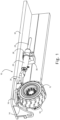
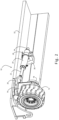
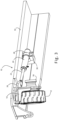
- a steering system 10 for a vehicle wheel 12 is shown in perspective view.
- Fig. 1 shows the system when the wheel 12 is steered straight ahead.
- Fig. 2 shows the system when the wheel 12 is steered at right angles, i.e. having been turned 90° to steer in a sideward direction.
- Fig. 3 shows the system when the wheel 12 is steered to its maximum extent, beyond 90°, to a steering angle of approximately 135°.
- the wheel 12 is mounted on a wheel carrier 14 which in turn is mounted on a bearing or hub 16 which permits the wheel to be rotated about a vertical axis relative to the chassis 32 of a vehicle.
- the nature of the vehicle drive system, and the coupling of the drive system to the wheel is not essential to the steering system and can be varied according to the preferences of the designer or manufacturer. So, for example, instead of a hydraulic or electric motor mounted on the wheel, an engine could be coupled to the wheel using a drive shaft or a gearing assembly. The engine could be internal combustion, hybrid, electrical, hydraulic or of any other kind.
- a hydraulic cylinder 20 which has an active connecting rod 22 ( Figs. 2 and 3 , hidden in Fig. 1 ) and a passive rod 24.
- the connecting rod 22 constitutes a first section of a rigid connecting rod assembly, and is adapted to reciprocate into and out of the cylinder.
- Fig. 1 shows the system when the connecting rod is withdrawn fully into the cylinder 20
- Fig. 2 shows the connecting rod 20 having been driven out partway from the cylinder
- Fig. 3 shows the connecting rod at its maximum extension from the cylinder.
- a second section 26 of the rigid connecting rod assembly is provided in the form of a rigid steel plate which is rigidly coupled (i.e. with no freedom of movement, rotation or pivoting) to the connecting rod 22.
- the connecting rod 22 is reciprocated into and out of the cylinder 20
- the second section is driven correspondingly towards and away from the cylinder in a straight line.
- the passive rod 24 is uncoupled at its free end and serves to allow the cylinder to be hydraulically coupled to and synchronized with a cylinder of a steering system for another wheel in a push-pull manner described further below.
- This passive rod could be dispensed with if such synchronization is not required, or could be substituted by an alternative synchronization mechanism such as a separate synchronizing cylinder or by appropriate hydraulic pumping circuits driving a steering mechanism on another wheel.
- a priming valve (not shown) is provided in the piston. As is known in the art, such a priming valve is useful for priming the system on initial start-up and for keeping the cylinders primed and synchronized in use in a multi-cylinder system such as is described in relation to Figs. 7-10 .
- the hydraulic cylinder is pivotally mounted on the vehicle such that it is prevented from translational movement relative to the vehicle but capable of changing its orientation with respect to the vehicle.
- the pivot mount is provided by a collar 28 affixed to the outside of the cylinder, with the collar being trunnion mounted in a fixed bracket 30 that is welded to the vehicle chassis 32.
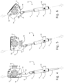
- FIG. 4-6 the operation of the steering system for a vehicle wheel is shown in plan view.
- the distal end of the second section 26 (i.e. the end remote from the cylinder) is pivotally coupled to the wheel carrier 14 at a pivot point 50.
- this pivot point 50 is offset from the centre of rotation 52 of the bearing 16, it translates laterally relative to the cylinder 20 as the connecting rod is extended. Due to the pivot mounting of the cylinder 20 on the chassis, the cylinder orientation changes as the connecting rod extends, as can be seen in the progression from Fig. 4 to Fig. 6 .
- the second section 26 is in the form of a curved member extending between the first section 22 and the pivot point connection 50.
- the curved member defines a concavity 54 which may accommodate a portion of the wheel carrier. This can be seen in Fig. 6 where the concavity 54 accommodates part of the wheel carrier below the hub as the steering angle extends beyond 90° to its maximum angle (in this embodiment) of 135°.
- the arcuate shape of the second section 26 transmits the forces from the pivot point in a straight line passing through a part of the hub.
- the maximum steering angle may be more or less than 135°, according to the wishes of the designer.
- the second member could be mounted above the wheel carrier and accommodate part of the hub or bearing 16 in an alternative arrangement.
- the connecting rod 22 is fitted into and rigidly affixed (such a by welding) within a socket formed in the proximal end of the second section.
- rigid mounting arrangements can be employed also.
- the use of the term "assembly" does not imply that the first and second sections must be separate members that are assembled together.
- the rigid connecting rod assembly could be an integrally formed component with identifiable portions including a first portion or section adapted to reciprocate within the cylinder and a second portion or section extending from the first portion to the wheel carrier.
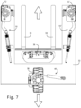
- the steering system for a vehicle wheel shown in Figs. 1-6 can be incorporated in an overall steering system for a vehicle, as shown in Figs. 7-10 .
- the vehicle in question is a forklift truck but the steering system can be implemented in any vehicle for which hydraulic steering is suitable.
- a forklift truck is shown in plan view.
- the view of the vehicle is simplified to show the chassis 32, the forks 34, the fork-lifting mechanism 36, and the wheels and steering arrangement, which will now be described.
- a right front wheel 12' is controlled by a steering system 10' which is a mirror image of the steering system 10.
- a steerable, driven rear wheel is mounted with its own (conventional) steering cylinder 40.
- the conventional steering cylinder could be replaced with a steering system for a vehicle wheel according to the invention.
- the vehicle is shown in Fig. 7 in normal steering mode. All three wheels 12, 12', 28 are aligned with the front-rear axis of the vehicle, i.e. aligned parallel with the forks 34.
- the steering systems 10, 10' may be inactive with the front wheels fixed, and the vehicle can be steered by the rear wheel alone, i.e. withdrawing or extending the rod from cylinder 40 to rotate the rear wheel 38 about its vertical axis.
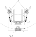
- Fig. 8 the vehicle is shown in sideward mode.
- the rear wheel 38 has been turned through 90°to be aligned perpendicular to the front-rear axis of the vehicle, so that the vehicle can be driven sideways and steered using the front wheels 12, 12'.
- the rear wheel 38 is fixed in position and follows an arc whose direction of curvature and radius are determined by the angle of the front wheels 12, 12'.
- the respective cylinders of the steering systems 10, 10' of each front wheel are synchronized so that, as shown in Fig. 8 , the angle adopted by left front wheel 12 is mirrored by wheel 12' in the opposite direction.
- the two steering systems for a vehicle wheel together form part of an overall vehicle steering system, which is shown in Figs. 9 and 10 .
- a hydraulic circuit which comprises a control circuit 42, a left-hand pressure line 44 leading to/from port L of the control circuit, a bridging line 46, and a right-hand pressure line 48 leading to/from port R.
- Each cylinder has a front chamber (with the connecting rod 22, see Figs. 1-6 ) and a rear chamber (with the passive rod 24), the chambers being filled with hydraulic fluid and separated by the piston on which the rods are mounted.
- the front chamber of system 10 is connected to left-hand pressure line 44.
- the rear chamber of system 10 is connected to the front chamber of system 10' by the bridging line 46.
- the rear chamber of system 10' is connected to right-hand pressure line 48.
- the cylinder volumes are equal and the system is balanced so that, as shown in Fig. 9 , both pistons adopt the same position along their respective cylinders.
- the control circuit 42 has ports P and T connecting to a hydraulic pump and tank, respectively.
- a rotary pump 44 is controlled by a shaft 46 of a steering column so that rotation of the steering column in one direction causes hydraulic fluid to be pumped through port L into line 44 (and a corresponding volume of fluid to be returned via port R), while rotation of the column in the other direction causes the opposite flow to occur.
- An arrangement of one-way valves and solenoid valves 48 handles the resulting flow of hydraulic fluid within the circuit.
- the overall vehicle steering system for the front wheels has the same advantages on each side as the single wheel steering system of Figs. 1-6 , providing accurate steering beyond 90 degrees with no lateral forces being exerted on the seals of the hydraulic cylinders.
Landscapes
- Engineering & Computer Science (AREA)
- Transportation (AREA)
- Mechanical Engineering (AREA)
- Chemical & Material Sciences (AREA)
- Combustion & Propulsion (AREA)
- Structural Engineering (AREA)
- Civil Engineering (AREA)
- Life Sciences & Earth Sciences (AREA)
- Geology (AREA)
- Steering-Linkage Mechanisms And Four-Wheel Steering (AREA)
- Power Steering Mechanism (AREA)
Claims (12)
- Système de direction pour roue de véhicule, comprenant :un support de roue (14) permettant de monter une roue directrice, le support de roue (14) étant monté de manière rotative par rapport au véhicule autour d'un axe de direction pour permettre à la roue d'être dirigée ;un cylindre hydraulique (20) présentant un piston à l'intérieur et un ensemble de bielle rigide se prolongeant du piston jusqu'en dehors du cylindre ;dans lequel l'ensemble de bielle rigide comprend une première section (22) conçue pour effectuer un mouvement de va-et-vient dans et hors du cylindre et une seconde section (26) se prolongeant de manière rigide depuis la première section (22) vers un raccord de point de pivot où elle est reliée de manière rotative au support de roue (14) à un décalage par rapport à l'axe de direction ;dans lequel la seconde section (26) est un élément incurvé se prolongeant entre la première section (22) et le raccord de point de pivot, l'élément incurvé étant façonné pour définir une concavité permettant de loger une partie du support de roue (14) à l'intérieur de la concavité ; etdans lequel le cylindre hydraulique (20) est monté de manière rotative sur le véhicule de manière à empêcher tout mouvement de translation par rapport au véhicule, mais peut changer d'orientation par rapport au véhicule.
- Système de direction selon la revendication 1, dans lequel ladite première section (22) est une section de tige linéaire droite et ledit point de pivot est disposé en alignement linéaire avec la première section (22).
- Système de direction selon la revendication 2, dans lequel ledit point de pivot, le point auquel les seconde et première sections sont couplées de manière rigide, l'axe de la première section (22), l'axe du cylindre et la position à laquelle le cylindre est monté de manière rotative sur le véhicule sont tous colinéaires.
- Système de direction selon la revendication 1, dans lequel la concavité loge une partie du support de roue (14) lorsque l'angle de direction est à son maximum dans une direction.
- Système de direction selon la revendication 1 ou 4, dans lequel ladite seconde section (26) est un élément arqué.
- Système de direction selon une quelconque revendication précédente, dans lequel l'ensemble de bielle est une structure formée d'un seul tenant présentant lesdites première et seconde sections.
- Système de direction selon l'une quelconque des revendications 1 à 5, dans lequel l'ensemble de bielle comprend une bielle comme étant ledit premier élément et un élément d'extension fixé de manière rigide à la bielle comme étant ledit second élément.
- Système de direction selon une quelconque revendication précédente, comprenant également une tige passive (24) se prolongeant depuis le cylindre dans la direction opposée à la bielle et montée sur un piston commun ou un ensemble de piston avec celui-ci, la tige passive (24) scellant le cylindre dans la direction opposée à la roue et permettant la synchronisation du cylindre avec un autre cylindre hydraulique dans un agencement de poussée et de traction.
- Système de direction selon une quelconque revendication précédente, comprenant également une roue montée sur ledit support de roue (14).
- Système de direction selon une quelconque revendication précédente, comprenant également un circuit hydraulique comportant une pompe hydraulique (44), un raccord depuis la pompe hydraulique vers le cylindre hydraulique, et un moyen de contrôle du débit de fluide hydraulique à l'intérieur du circuit hydraulique en réponse à une entrée de direction.
- Système de direction de véhicule comprenant un premier système de direction pour une première roue de véhicule selon l'une quelconque des revendications 1 à 10, un second système de direction pour une seconde roue de véhicule selon l'une quelconque des revendications 1 à 10 et un circuit hydraulique reliant les cylindres hydrauliques des premier et second systèmes de direction en série.
- Véhicule comprenant un système de direction selon l'une quelconque des revendications 1 à 11.
Applications Claiming Priority (2)
| Application Number | Priority Date | Filing Date | Title |
|---|---|---|---|
| GB1803601.2A GB2571736A (en) | 2018-03-06 | 2018-03-06 | Hydraulic steering systems for vehicle wheels |
| PCT/EP2019/051235 WO2019170310A1 (fr) | 2018-03-06 | 2019-01-18 | Systèmes de direction hydraulique pour roues de véhicule |
Publications (3)
| Publication Number | Publication Date |
|---|---|
| EP3762275A1 EP3762275A1 (fr) | 2021-01-13 |
| EP3762275C0 EP3762275C0 (fr) | 2025-05-21 |
| EP3762275B1 true EP3762275B1 (fr) | 2025-05-21 |
Family
ID=61903476
Family Applications (1)
| Application Number | Title | Priority Date | Filing Date |
|---|---|---|---|
| EP19701325.3A Active EP3762275B1 (fr) | 2018-03-06 | 2019-01-18 | Systèmes de direction hydraulique pour roues de véhicule |
Country Status (9)
| Country | Link |
|---|---|
| US (1) | US11352052B2 (fr) |
| EP (1) | EP3762275B1 (fr) |
| CN (1) | CN111788109B (fr) |
| AU (1) | AU2019232219B2 (fr) |
| CA (1) | CA3091756A1 (fr) |
| GB (1) | GB2571736A (fr) |
| MX (1) | MX2020009156A (fr) |
| RU (1) | RU2766920C1 (fr) |
| WO (1) | WO2019170310A1 (fr) |
Families Citing this family (5)
| Publication number | Priority date | Publication date | Assignee | Title |
|---|---|---|---|---|
| DE102019116688A1 (de) * | 2019-06-19 | 2020-12-24 | 4Activesystems Gmbh | Verfahrbare Plattform für ein Dummy-Element |
| WO2022051342A1 (fr) * | 2020-09-01 | 2022-03-10 | Urbineer Inc | Système de manipulation de fret motorisé robotisé |
| GB202101426D0 (en) * | 2021-02-02 | 2021-03-17 | Combilift | Steering systems for lift trucks |
| CN114312991B (zh) * | 2022-03-07 | 2022-05-17 | 深圳小象电动科技有限公司 | 一种集成转向机构的轮边动力模组 |
| CN115158448A (zh) * | 2022-07-07 | 2022-10-11 | 安徽宇锋智能科技有限公司 | 一种全向车转向机构 |
Citations (1)
| Publication number | Priority date | Publication date | Assignee | Title |
|---|---|---|---|---|
| WO2014075921A1 (fr) * | 2012-11-15 | 2014-05-22 | Hubtex Maschinenbau Gmbh & Co. Kg | Système de direction pour un chariot de manutention |
Family Cites Families (16)
| Publication number | Priority date | Publication date | Assignee | Title |
|---|---|---|---|---|
| US3075784A (en) * | 1960-08-08 | 1963-01-29 | Hough Co Frank | Four wheel tractor steering arrangement |
| US3446307A (en) * | 1967-02-13 | 1969-05-27 | Pettibone Mulliken Corp | Selective steering with single valve |
| US4498554A (en) * | 1982-05-03 | 1985-02-12 | Young Roy E | Highly maneuverable prime mover |
| US4718686A (en) * | 1984-10-24 | 1988-01-12 | Zahnradfabrik Friedrichshafen Ag | Steering arrangement for motor vehicles |
| FR2694535B1 (fr) * | 1992-08-07 | 1994-10-14 | Bobard Jeune Sa Ets | Véhicule à direction hydraulique. |
| DE19714485A1 (de) * | 1997-04-08 | 1998-10-15 | Kidde Ind Inc | Lenkung für ein mehrachsiges Fahrzeug |
| JP3140012B2 (ja) * | 1999-05-21 | 2001-03-05 | ティー・シー・エム株式会社 | 横行システムを持ったフォークリフト |
| IT1321177B1 (it) * | 2000-04-21 | 2003-12-30 | Carrelli Elevatori Cesab | Carrello elevatore a raggio di sterzatura ridotto . |
| DE10052339B4 (de) * | 2000-10-21 | 2009-11-26 | Man Nutzfahrzeuge Ag | Hilfslenkeinrichtung einer Fahrzeugachse |
| CA2584917A1 (fr) * | 2006-04-13 | 2007-10-13 | W. Craig Coltson | Vehicule compact avec mobilite amelioree |
| DE102006018390A1 (de) * | 2006-04-20 | 2008-05-29 | Zf Lenksysteme Gmbh | Hilfskraftlenksystem für Fahrzeuge |
| CN201124866Y (zh) * | 2007-11-14 | 2008-10-01 | 安徽合力股份有限公司 | 上置式横置油缸叉车转向桥 |
| US8353377B2 (en) * | 2009-10-06 | 2013-01-15 | Deere & Company | Steering cylinder mounting arrangement used with a length-adjustable axle |
| CN204184132U (zh) * | 2014-09-22 | 2015-03-04 | 安徽合力股份有限公司安庆车桥厂 | 四支点叉车用油缸上置式转向桥 |
| CN206797471U (zh) * | 2017-04-28 | 2017-12-26 | 周文翔 | 一种具有四轮驱动以及四轮转向功能的底盘 |
| US10421484B2 (en) * | 2017-06-30 | 2019-09-24 | Cnh Industrial America Llc | Rear axle steering system and methods of using the same |
-
2018
- 2018-03-06 GB GB1803601.2A patent/GB2571736A/en not_active Withdrawn
-
2019
- 2019-01-18 CA CA3091756A patent/CA3091756A1/fr active Pending
- 2019-01-18 CN CN201980015790.1A patent/CN111788109B/zh active Active
- 2019-01-18 RU RU2020128557A patent/RU2766920C1/ru active
- 2019-01-18 AU AU2019232219A patent/AU2019232219B2/en active Active
- 2019-01-18 MX MX2020009156A patent/MX2020009156A/es unknown
- 2019-01-18 US US16/978,309 patent/US11352052B2/en active Active
- 2019-01-18 EP EP19701325.3A patent/EP3762275B1/fr active Active
- 2019-01-18 WO PCT/EP2019/051235 patent/WO2019170310A1/fr not_active Ceased
Patent Citations (1)
| Publication number | Priority date | Publication date | Assignee | Title |
|---|---|---|---|---|
| WO2014075921A1 (fr) * | 2012-11-15 | 2014-05-22 | Hubtex Maschinenbau Gmbh & Co. Kg | Système de direction pour un chariot de manutention |
Also Published As
| Publication number | Publication date |
|---|---|
| US20210001920A1 (en) | 2021-01-07 |
| EP3762275C0 (fr) | 2025-05-21 |
| WO2019170310A1 (fr) | 2019-09-12 |
| GB201803601D0 (en) | 2018-04-18 |
| GB2571736A (en) | 2019-09-11 |
| EP3762275A1 (fr) | 2021-01-13 |
| CN111788109B (zh) | 2022-10-04 |
| RU2766920C1 (ru) | 2022-03-16 |
| MX2020009156A (es) | 2020-10-05 |
| AU2019232219A1 (en) | 2020-09-24 |
| BR112020017620A2 (pt) | 2020-12-22 |
| CN111788109A (zh) | 2020-10-16 |
| US11352052B2 (en) | 2022-06-07 |
| AU2019232219B2 (en) | 2024-08-29 |
| CA3091756A1 (fr) | 2019-09-12 |
Similar Documents
| Publication | Publication Date | Title |
|---|---|---|
| EP3762275B1 (fr) | Systèmes de direction hydraulique pour roues de véhicule | |
| CN111619662B (zh) | 一种4x4机电液全轮转向系统的前后桥反向转向方法 | |
| CN111619648B (zh) | 一种方向盘及转向器总成以及转向系统 | |
| WO2004062956A1 (fr) | Dispositif d'entrainement d'essieu hydraulique | |
| US8156738B2 (en) | Hydrostatic transmission having two axial piston units | |
| EP0737612B1 (fr) | Système de direction pour une machine articulée | |
| US20060201735A1 (en) | Steering apparatus | |
| HK40042246B (en) | Hydraulic steering systems for vehicle wheels | |
| HK40042246A (en) | Hydraulic steering systems for vehicle wheels | |
| US7389849B2 (en) | Steering apparatus with plural motors | |
| US20210331738A1 (en) | Rear steering hydraulic system | |
| US20080308341A1 (en) | Vehicle Steering System and Method for Controlling a Vehicle Steering System | |
| EP2029415B1 (fr) | Remorque directrice ou semi-remorque | |
| CN117163152A (zh) | 转向系统和工程车辆 | |
| CN111874092B (zh) | 一种转向回位锁止机构总成操作系统 | |
| CN111845928B (zh) | 一种前桥转向油罐总成以及转向系统 | |
| US11072365B1 (en) | Pneumatic power steering system | |
| BR112020017620B1 (pt) | Sistemas de direção hidráulica para roda de veículos e veículo | |
| US11427248B2 (en) | Rear steering hydraulic system | |
| JPH08169352A (ja) | 駆動操舵装置 | |
| JP2585826Y2 (ja) | 多軸車における複数転舵時の異常入力制限機構 | |
| JPH06286635A (ja) | 車両の後輪操舵装置の組立方法 | |
| JP2000272527A (ja) | 動力舵取装置 | |
| JPH03262776A (ja) | 四輪操舵装置 | |
| JPS61200062A (ja) | 車両操舵装置 |
Legal Events
| Date | Code | Title | Description |
|---|---|---|---|
| STAA | Information on the status of an ep patent application or granted ep patent |
Free format text: STATUS: UNKNOWN |
|
| STAA | Information on the status of an ep patent application or granted ep patent |
Free format text: STATUS: THE INTERNATIONAL PUBLICATION HAS BEEN MADE |
|
| PUAI | Public reference made under article 153(3) epc to a published international application that has entered the european phase |
Free format text: ORIGINAL CODE: 0009012 |
|
| STAA | Information on the status of an ep patent application or granted ep patent |
Free format text: STATUS: REQUEST FOR EXAMINATION WAS MADE |
|
| 17P | Request for examination filed |
Effective date: 20200821 |
|
| AK | Designated contracting states |
Kind code of ref document: A1 Designated state(s): AL AT BE BG CH CY CZ DE DK EE ES FI FR GB GR HR HU IE IS IT LI LT LU LV MC MK MT NL NO PL PT RO RS SE SI SK SM TR |
|
| AX | Request for extension of the european patent |
Extension state: BA ME |
|
| DAV | Request for validation of the european patent (deleted) | ||
| DAX | Request for extension of the european patent (deleted) | ||
| REG | Reference to a national code |
Ref country code: HK Ref legal event code: DE Ref document number: 40042246 Country of ref document: HK |
|
| STAA | Information on the status of an ep patent application or granted ep patent |
Free format text: STATUS: EXAMINATION IS IN PROGRESS |
|
| 17Q | First examination report despatched |
Effective date: 20221205 |
|
| GRAP | Despatch of communication of intention to grant a patent |
Free format text: ORIGINAL CODE: EPIDOSNIGR1 |
|
| STAA | Information on the status of an ep patent application or granted ep patent |
Free format text: STATUS: GRANT OF PATENT IS INTENDED |
|
| INTG | Intention to grant announced |
Effective date: 20241206 |
|
| GRAS | Grant fee paid |
Free format text: ORIGINAL CODE: EPIDOSNIGR3 |
|
| GRAA | (expected) grant |
Free format text: ORIGINAL CODE: 0009210 |
|
| STAA | Information on the status of an ep patent application or granted ep patent |
Free format text: STATUS: THE PATENT HAS BEEN GRANTED |
|
| AK | Designated contracting states |
Kind code of ref document: B1 Designated state(s): AL AT BE BG CH CY CZ DE DK EE ES FI FR GB GR HR HU IE IS IT LI LT LU LV MC MK MT NL NO PL PT RO RS SE SI SK SM TR |
|
| REG | Reference to a national code |
Ref country code: GB Ref legal event code: FG4D |
|
| REG | Reference to a national code |
Ref country code: CH Ref legal event code: EP |
|
| REG | Reference to a national code |
Ref country code: DE Ref legal event code: R096 Ref document number: 602019070199 Country of ref document: DE |
|
| REG | Reference to a national code |
Ref country code: IE Ref legal event code: FG4D |
|
| U01 | Request for unitary effect filed |
Effective date: 20250618 |
|
| U07 | Unitary effect registered |
Designated state(s): AT BE BG DE DK EE FI FR IT LT LU LV MT NL PT RO SE SI Effective date: 20250627 |
|
| PG25 | Lapsed in a contracting state [announced via postgrant information from national office to epo] |
Ref country code: ES Free format text: LAPSE BECAUSE OF FAILURE TO SUBMIT A TRANSLATION OF THE DESCRIPTION OR TO PAY THE FEE WITHIN THE PRESCRIBED TIME-LIMIT Effective date: 20250521 |
|
| PG25 | Lapsed in a contracting state [announced via postgrant information from national office to epo] |
Ref country code: GR Free format text: LAPSE BECAUSE OF FAILURE TO SUBMIT A TRANSLATION OF THE DESCRIPTION OR TO PAY THE FEE WITHIN THE PRESCRIBED TIME-LIMIT Effective date: 20250822 |
|
| PG25 | Lapsed in a contracting state [announced via postgrant information from national office to epo] |
Ref country code: PL Free format text: LAPSE BECAUSE OF FAILURE TO SUBMIT A TRANSLATION OF THE DESCRIPTION OR TO PAY THE FEE WITHIN THE PRESCRIBED TIME-LIMIT Effective date: 20250521 |
|
| PG25 | Lapsed in a contracting state [announced via postgrant information from national office to epo] |
Ref country code: HR Free format text: LAPSE BECAUSE OF FAILURE TO SUBMIT A TRANSLATION OF THE DESCRIPTION OR TO PAY THE FEE WITHIN THE PRESCRIBED TIME-LIMIT Effective date: 20250521 |
|
| PG25 | Lapsed in a contracting state [announced via postgrant information from national office to epo] |
Ref country code: RS Free format text: LAPSE BECAUSE OF FAILURE TO SUBMIT A TRANSLATION OF THE DESCRIPTION OR TO PAY THE FEE WITHIN THE PRESCRIBED TIME-LIMIT Effective date: 20250821 |
|
| PG25 | Lapsed in a contracting state [announced via postgrant information from national office to epo] |
Ref country code: IS Free format text: LAPSE BECAUSE OF FAILURE TO SUBMIT A TRANSLATION OF THE DESCRIPTION OR TO PAY THE FEE WITHIN THE PRESCRIBED TIME-LIMIT Effective date: 20250921 |
|
| U20 | Renewal fee for the european patent with unitary effect paid |
Year of fee payment: 8 Effective date: 20251126 |
|
| PGFP | Annual fee paid to national office [announced via postgrant information from national office to epo] |
Ref country code: GB Payment date: 20251120 Year of fee payment: 8 |
|
| PG25 | Lapsed in a contracting state [announced via postgrant information from national office to epo] |
Ref country code: SM Free format text: LAPSE BECAUSE OF FAILURE TO SUBMIT A TRANSLATION OF THE DESCRIPTION OR TO PAY THE FEE WITHIN THE PRESCRIBED TIME-LIMIT Effective date: 20250521 |
|
| PG25 | Lapsed in a contracting state [announced via postgrant information from national office to epo] |
Ref country code: CZ Free format text: LAPSE BECAUSE OF FAILURE TO SUBMIT A TRANSLATION OF THE DESCRIPTION OR TO PAY THE FEE WITHIN THE PRESCRIBED TIME-LIMIT Effective date: 20250521 |
|
| PGFP | Annual fee paid to national office [announced via postgrant information from national office to epo] |
Ref country code: IE Payment date: 20251112 Year of fee payment: 8 |
|
| PG25 | Lapsed in a contracting state [announced via postgrant information from national office to epo] |
Ref country code: SK Free format text: LAPSE BECAUSE OF FAILURE TO SUBMIT A TRANSLATION OF THE DESCRIPTION OR TO PAY THE FEE WITHIN THE PRESCRIBED TIME-LIMIT Effective date: 20250521 |
|
| PLBE | No opposition filed within time limit |
Free format text: ORIGINAL CODE: 0009261 |
|
| STAA | Information on the status of an ep patent application or granted ep patent |
Free format text: STATUS: NO OPPOSITION FILED WITHIN TIME LIMIT |
|
| REG | Reference to a national code |
Ref country code: CH Ref legal event code: L10 Free format text: ST27 STATUS EVENT CODE: U-0-0-L10-L00 (AS PROVIDED BY THE NATIONAL OFFICE) Effective date: 20260402 |
|
| PGFP | Annual fee paid to national office [announced via postgrant information from national office to epo] |
Ref country code: NO Payment date: 20260120 Year of fee payment: 8 |
|
| 26N | No opposition filed |
Effective date: 20260224 |