EP3762320B1 - Dispositif d'aspiration pour l'aspiration d'un matériau d'extrusion vers un récipient collecteur d'un dispositif d'extrusion et méthode pour son vidage - Google Patents
Dispositif d'aspiration pour l'aspiration d'un matériau d'extrusion vers un récipient collecteur d'un dispositif d'extrusion et méthode pour son vidage Download PDFInfo
- Publication number
- EP3762320B1 EP3762320B1 EP19709422.0A EP19709422A EP3762320B1 EP 3762320 B1 EP3762320 B1 EP 3762320B1 EP 19709422 A EP19709422 A EP 19709422A EP 3762320 B1 EP3762320 B1 EP 3762320B1
- Authority
- EP
- European Patent Office
- Prior art keywords
- suction
- valve
- line
- extrusion
- opening
- Prior art date
- Legal status (The legal status is an assumption and is not a legal conclusion. Google has not performed a legal analysis and makes no representation as to the accuracy of the status listed.)
- Active
Links
Images


Classifications
-
- B—PERFORMING OPERATIONS; TRANSPORTING
- B29—WORKING OF PLASTICS; WORKING OF SUBSTANCES IN A PLASTIC STATE IN GENERAL
- B29C—SHAPING OR JOINING OF PLASTICS; SHAPING OF MATERIAL IN A PLASTIC STATE, NOT OTHERWISE PROVIDED FOR; AFTER-TREATMENT OF THE SHAPED PRODUCTS, e.g. REPAIRING
- B29C48/00—Extrusion moulding, i.e. expressing the moulding material through a die or nozzle which imparts the desired form; Apparatus therefor
- B29C48/25—Component parts, details or accessories; Auxiliary operations
- B29C48/255—Flow control means, e.g. valves
- B29C48/2552—Flow control means, e.g. valves provided in the feeding, melting, plasticising or pumping zone, e.g. screw, barrel, gear-pump or ram
-
- B—PERFORMING OPERATIONS; TRANSPORTING
- B29—WORKING OF PLASTICS; WORKING OF SUBSTANCES IN A PLASTIC STATE IN GENERAL
- B29B—PREPARATION OR PRETREATMENT OF THE MATERIAL TO BE SHAPED; MAKING GRANULES OR PREFORMS; RECOVERY OF PLASTICS OR OTHER CONSTITUENTS OF WASTE MATERIAL CONTAINING PLASTICS
- B29B7/00—Mixing; Kneading
- B29B7/30—Mixing; Kneading continuous, with mechanical mixing or kneading devices
- B29B7/58—Component parts, details or accessories; Auxiliary operations
- B29B7/60—Component parts, details or accessories; Auxiliary operations for feeding, e.g. end guides for the incoming material
-
- B—PERFORMING OPERATIONS; TRANSPORTING
- B29—WORKING OF PLASTICS; WORKING OF SUBSTANCES IN A PLASTIC STATE IN GENERAL
- B29C—SHAPING OR JOINING OF PLASTICS; SHAPING OF MATERIAL IN A PLASTIC STATE, NOT OTHERWISE PROVIDED FOR; AFTER-TREATMENT OF THE SHAPED PRODUCTS, e.g. REPAIRING
- B29C48/00—Extrusion moulding, i.e. expressing the moulding material through a die or nozzle which imparts the desired form; Apparatus therefor
- B29C48/25—Component parts, details or accessories; Auxiliary operations
- B29C48/269—Extrusion in non-steady condition, e.g. start-up or shut-down
- B29C48/2692—Material change
-
- B—PERFORMING OPERATIONS; TRANSPORTING
- B29—WORKING OF PLASTICS; WORKING OF SUBSTANCES IN A PLASTIC STATE IN GENERAL
- B29C—SHAPING OR JOINING OF PLASTICS; SHAPING OF MATERIAL IN A PLASTIC STATE, NOT OTHERWISE PROVIDED FOR; AFTER-TREATMENT OF THE SHAPED PRODUCTS, e.g. REPAIRING
- B29C48/00—Extrusion moulding, i.e. expressing the moulding material through a die or nozzle which imparts the desired form; Apparatus therefor
- B29C48/25—Component parts, details or accessories; Auxiliary operations
- B29C48/27—Cleaning; Purging; Avoiding contamination
- B29C48/271—Cleaning; Purging; Avoiding contamination of feeding units
-
- B—PERFORMING OPERATIONS; TRANSPORTING
- B29—WORKING OF PLASTICS; WORKING OF SUBSTANCES IN A PLASTIC STATE IN GENERAL
- B29C—SHAPING OR JOINING OF PLASTICS; SHAPING OF MATERIAL IN A PLASTIC STATE, NOT OTHERWISE PROVIDED FOR; AFTER-TREATMENT OF THE SHAPED PRODUCTS, e.g. REPAIRING
- B29C48/00—Extrusion moulding, i.e. expressing the moulding material through a die or nozzle which imparts the desired form; Apparatus therefor
- B29C48/25—Component parts, details or accessories; Auxiliary operations
- B29C48/285—Feeding the extrusion material to the extruder
-
- B—PERFORMING OPERATIONS; TRANSPORTING
- B65—CONVEYING; PACKING; STORING; HANDLING THIN OR FILAMENTARY MATERIAL
- B65G—TRANSPORT OR STORAGE DEVICES, e.g. CONVEYORS FOR LOADING OR TIPPING, SHOP CONVEYOR SYSTEMS OR PNEUMATIC TUBE CONVEYORS
- B65G53/00—Conveying materials in bulk through troughs, pipes or tubes by floating the materials or by flow of gas, liquid or foam
- B65G53/04—Conveying materials in bulk pneumatically through pipes or tubes; Air slides
- B65G53/06—Gas pressure systems operating without fluidisation of the materials
- B65G53/10—Gas pressure systems operating without fluidisation of the materials with pneumatic injection of the materials by the propelling gas
- B65G53/14—Gas pressure systems operating without fluidisation of the materials with pneumatic injection of the materials by the propelling gas the gas flow inducing feed of the materials by suction effect
-
- B—PERFORMING OPERATIONS; TRANSPORTING
- B65—CONVEYING; PACKING; STORING; HANDLING THIN OR FILAMENTARY MATERIAL
- B65G—TRANSPORT OR STORAGE DEVICES, e.g. CONVEYORS FOR LOADING OR TIPPING, SHOP CONVEYOR SYSTEMS OR PNEUMATIC TUBE CONVEYORS
- B65G53/00—Conveying materials in bulk through troughs, pipes or tubes by floating the materials or by flow of gas, liquid or foam
- B65G53/34—Details
- B65G53/40—Feeding or discharging devices
- B65G53/42—Nozzles
-
- B—PERFORMING OPERATIONS; TRANSPORTING
- B65—CONVEYING; PACKING; STORING; HANDLING THIN OR FILAMENTARY MATERIAL
- B65G—TRANSPORT OR STORAGE DEVICES, e.g. CONVEYORS FOR LOADING OR TIPPING, SHOP CONVEYOR SYSTEMS OR PNEUMATIC TUBE CONVEYORS
- B65G53/00—Conveying materials in bulk through troughs, pipes or tubes by floating the materials or by flow of gas, liquid or foam
- B65G53/34—Details
- B65G53/58—Devices for accelerating or decelerating flow of the materials; Use of pressure generators
-
- B—PERFORMING OPERATIONS; TRANSPORTING
- B65—CONVEYING; PACKING; STORING; HANDLING THIN OR FILAMENTARY MATERIAL
- B65G—TRANSPORT OR STORAGE DEVICES, e.g. CONVEYORS FOR LOADING OR TIPPING, SHOP CONVEYOR SYSTEMS OR PNEUMATIC TUBE CONVEYORS
- B65G53/00—Conveying materials in bulk through troughs, pipes or tubes by floating the materials or by flow of gas, liquid or foam
- B65G53/34—Details
- B65G53/66—Use of indicator or control devices, e.g. for controlling gas pressure, for controlling proportions of material and gas, for indicating or preventing jamming of material
Definitions
- the present invention relates to a suction device for sucking in extrusion material to a storage container of an extrusion device and a method for emptying a suction line of an extrusion device.
- extrusion devices should be supplied with granular extrusion material. Mixtures of different material components are usually collected in a storage container of the extrusion device. Storage containers of extrusion devices are connected to corresponding granulate containers or granulate silos in order to be loaded. From sacks of granules For example, the desired granules can be conveyed into the storage tank with the help of suction lances.
- a disadvantage of the known solutions is that when different material mixtures are changed in the storage tank, residual material remains in the suction lines or the suction devices.
- a suction lance is usually inserted from an input material into a sack filled with follow-up material.
- the input material is still the input material in the suction device and in the associated suction hose or the associated suction line, so that for the first subsequent conveyances, despite the connection to the subsequent material due to the presence of the input material in the suction line, this input material is left as a residue in the storage container reached.
- a suction device is used to suction extrusion material to a storage container of an extrusion device via a suction line.
- the suction device is equipped with a suction interface with a suction opening for sucking in extrusion material.
- the intake device has a line interface for connection to the intake line.
- the suction port is connected to the line interface for conveying extrusion material via an internal conveying line.
- the suction device has a valve device which, in an open position, opens the delivery line to the environment and, in a closed position, closes the delivery line to the environment.
- an extrusion device is to be understood in particular as a component of a blown film extrusion device and/or a flat film extrusion device.
- the extrusion device is preferably designed as a blown film extrusion device and/or as a flat film extrusion device.
- the extrusion material is in particular designed as a plastic material or has a plastic content. Plastic in this sense is preferably designed as a fusible and extrudable material, e.g. in the form of a thermoplastic material.
- the extrusion material is particularly preferably made entirely or essentially entirely of plastic.
- the extrusion material is in particular in pourable and/or free-flowing form.
- the extrusion material can have extruded granulate and/or extruded particles.
- a suction device is used in known solutions of extrusion devices and storage containers.
- the suction of extrusion material as input material via the suction opening of the suction interface can be ensured with the aid of the suction device, which can be designed, for example, as a suction lance.
- the sucked-in extrusion material is passed on to a suction line via the line interface and in this way, in a known implementation, it is conveyed into the storage container.
- the suction device is usually connected to a new follow-on material in the form of a silo or a granulate bag. If the suction device is a suction lance, it is inserted from a sack with input material into a sack with follow-up material. At this point in time, i.e. after reconnecting or switching over the suction device, the input material is still inside the suction device, in particular in the internal delivery line and subsequently in the suction line, which is connected to the suction device via the line interface. While in known solutions the input material remaining in the storage container would first have reached the storage container during the next replenishment thrust, a preparatory step can now take place with a suction device according to the invention.
- the preparatory step mentioned above is ensured by opening the valve device, ie by switching from the closed position to the open position, in which the delivery line is open to the environment.
- the suction line can now be sucked free during suction while the suction device remains in the bag with the input material. If a negative pressure from the reservoir is applied to the suction device via the suction line, when the valve device is in the open position, feed material is no longer sucked in via the suction device, but rather air from the environment replaces the feed material sucked into the storage container from the suction line via the valve device . If the suction device is then connected to a new source of material or inserted into a bag with follow-on material, the suction line is free of the input material. During the first replenishment push into the storage container, a smaller proportion of input material is now introduced into the downstream device through the previously cleared part of the intake line. At this point the valve device is again in the closed position.
- the desired subsequent mixture becomes clear faster or after a shorter transition period.
- the waste material that is produced in such a transitional period is significantly reduced in this way.
- the core idea of the present invention is therefore to provide a valve device, so to speak, as a local valve on the intake device and/or in the area of the intake opening, in order to empty the intake line and/or at least part of the intake device through the opening to the environment to be able to provide.
- the switching of the valve device from the closed position to the open position is preferably designed to be reversible, ie it can take place several times.
- the suction device can thus carry out the process described above reversibly and repeatedly for any number of material changes. Movement between the closed position and the open position is also possible directly or indirectly.
- the valve device can thus directly have the valve opening which will be described later. In principle, however, it is also conceivable to connect a hose to the valve device for connection to the environment, in order to be able to provide increased safety and an optimized method in dusty environments, for example.
- Sealing in the closed position or closing off in the closed position is to be understood in particular as the entry of suction air. Sealing against the ingress of ambient air results in the negative pressure being made available exclusively or essentially exclusively for conveying extrusion material during normal operation. In addition, the locking of the valve device in the closed position also serves to prevent the escape of extrusion material.
- a suction device can be designed to be manual, semi-automatic or fully automated.
- a manual variant of the suction device is to be understood in particular as the suction lance already mentioned.
- a suction device represents a partially automated solution if it is a connection piece to the corresponding silo templates in which different extrusion materials are stored.
- this connection to a silo can also have its own switch or mixing device, so that the suction device can also be understood as an automated suction device in such a case.
- valve device has a valve opening and a valve closure in an intake device according to the invention, with the valve closure releasing the valve opening to the environment in the open position and the valve closure closing or closing the valve opening to the environment in the closed position.
- This is the simplest and most cost-effective structural design of such a valve device. Both direct and indirect access to the environment can be guaranteed here. In particular, complex and cost-intensive valve devices can be avoided here in order to be able to achieve the advantages according to the invention.
- a further advantage can be achieved if, in the case of an intake device according to the invention, the valve closure is acted upon in the closed position with a force, in particular with a spring force, in the direction of the open position.
- a valve closure now makes it possible to provide a pretension, so to speak, in order to facilitate the movement into the open position or even to be able to carry it out partially or automatically. If the force is great enough to automatically move the valve plug to the open position, a simple triggering force can release this force so that the valve plug automatically moves to the open position under the action of this force. If the valve closure is to be driven by a motor, the preload can provide support during opening, so that a smaller and more cost-effective motor provides fast opening functionality. Moving to the closed position is less critical in terms of time, since at this point in time it is a preparatory step that is outside of the current or active production cycle. In both cases, a partially automatic and/or even an automatic opening of the valve device is possible.
- the valve device has a triggering mechanism for releasing the spring force in direction of the opening position.
- a triggering mechanism can be designed mechanically, electrically and/or electromechanically.
- the triggering mechanism can be triggered with a triggering signal or a triggering impulse. This can be unidirectional or bidirectional. It is sufficient, in particular when a prestressing force is applied, if the triggering mechanism is subjected to a triggering signal and the valve closure automatically moves into the open position in this way. The reverse direction, ie closing in the closed position, can be ensured manually by the user of the suction device, for example.
- other connection options with two or more signal lines are also conceivable in order to be able to send back information about the status of the valve device to a higher-level control unit in a bidirectional communication option.
- the valve device has a signaling means for generating a valve signal at least when the open position and/or the closed position is reached.
- a higher-level control unit can evaluate corresponding signaling information.
- a valve signal can also give the operator or user of the intake device visual and/or acoustic feedback on the status of the valve device.
- This interrogation signal can be generated or made available both continuously and in a pulsed manner.
- a display device is provided, in particular on the valve device, for displaying the currently conveyed extrusion material.
- the user of the display device can distinguish directly on the display device whether it is the input material, the subsequent material or the preceding material.
- a display device is in particular an optical display device and can have, for example, an LED display or LED color displays.
- the display can be both qualitative and differentiate between two or three pieces of basic information in an abstract manner, ie between an input material, the subsequent material and/or the preceding material.
- the valve device has a drive means for automatically setting the valve device into the open position and/or the closed position.
- a drive means is in particular designed to be reversible, so that the open position and the closed position can be reached with the valve device by the drive means.
- a corresponding valve closure can be moved by the drive means.
- Setting other valve bodies with the help of the drive means is also conceivable here.
- the drive means acts at least in the opening direction, ie for a movement into the open position.
- the spring functionality already explained, ie the provision of a prestressing force, can be used in combination with a drive means in order to reduce the design, the size and the costs for such a drive means.
- the valve device in particular a valve opening, has an escape safeguard against the escape of extrusion material in the open position.
- an escape protection can be designed, for example, as a grid insert in a corresponding opening of the valve device.
- Other filters which serve to prevent solid particles escaping in the form of extrusion material, can also be used here.
- Such an escape protection is already provided by a reduced cross-section of the valve opening or a corresponding hose connection, for example with a shut-off grille.
- the present invention also relates to a suction line for sucking in extrusion material to a storage tank of an extrusion device.
- Such an intake line has a connection interface for connection to the line interface of an intake device according to the invention.
- the suction line is also equipped with a delivery interface for connection to the storage tank.
- a valve device is provided which, in an open position, opens the intake line to the environment and in a closed position closes the intake line to the environment.
- the valve device of the intake line can be designed identically to that explained in detail with reference to the intake device.
- the intake line thus brings with it the same advantages as it does in parallel for the intake device have been explained.
- the connection to the storage tank can be direct or indirect.
- Switch devices are also conceivable, which connect two or more parallel suction lines to a common storage tank.
- the advantages of the invention are achieved regardless of the location of the valve device.
- the valve device for achieving the optimization possibilities according to the invention can thus be arranged both in the intake line and in the intake device or only in one of these two assemblies.
- valve device is arranged in the connection interface and/or in the area of the connection interface.
- the shorter the path to the corresponding connection the longer the path to the delivery interface, so that a greater path of the suction line is actually available for this suction when the suction line is cleared or sucked free.
- the associated emptying length of the intake line is increased and in this way the transition time between feed material mixtures and follow-up material mixture is shortened.
- valve device according to the present invention is designed with an intake device.
- Another preferred subject of the present invention is an intake system with an intake line according to the invention and/or an intake device according to the invention.
- the suction device and/or the suction line can be sucked empty in the manner described when switching to the subsequent recipe.
- the method thus brings with it the same advantages as have been explained in detail with reference to an intake device according to the invention or with reference to an intake line according to the invention.
- the step of sucking in the extrusion material is carried out until the suction line and/or the conveying line is/are free or essentially free of extrusion material.
- the emptying length of the intake line is increased so that less of the feedstock remains in the intake system during the changeover to the follow-on material, thereby reducing the transition time to producing the follow-on material mixture.
- In 1 is shown schematically the overall system in combination of a storage tank 210, a suction line 100 and a suction device 10.
- the starting material is in the form of extrusion material EM in a storage tank, for example in a granulate bag.
- the extrusion material EM can now penetrate via the suction opening 22 into the suction interface 20 of this suction lance via a negative pressure in the storage container 200, which is passed on to the suction device 10 via the suction line 100.
- the extrusion material EM is passed on via the conveying line 40 in the suction device 10 until it is transferred to the line interface 30 .
- the extrusion material EM conveyed up to this point now penetrates via the connection interface 130 into the intake line 100 and is conveyed further there to the delivery interface 120 , where it penetrates into the storage container 210 .
- the storage container 210 is preferably equipped with two or more different extrusion materials EM and mixing takes place there before the mixed material can enter the extrusion device 200 as a material mixture.
- the suction line 100 and/or a part of the suction device 10 is also evacuated during positioning on the input material.
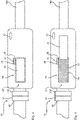
- a valve device 50 is provided on the intake device 10, as shown in detail in FIGS Figures 2 and 3 is shown.
- a valve closure 54 of the valve device 50 is in a closed position SP according to FIG 2 .
- a valve closure 54 closes the valve opening 52 in a sealing manner.
- the valve closure 54 is now moved into its open position OP according to FIG 3 transferred.
- the valve opening 52 is now uncovered here, except for the presence of an escape safeguard 53 against the undesired emergence or slipping out of extrusion material EM.
- a display device 60 can display both the status and the extrusion material EM conveyed here.
- a signaling means 58 which can provide a signaling of the current status of the valve device 50 or an existing drive means 51.
- the Figures 4 and 5 show a substantially identical design and operation of the valve device 50. However, here the arrangement of the valve device 56 is carried out in the intake line 100, while the Figures 2 and 3 provide the valve device 56 as part of the suction device 10 in the delivery line 40 .
Landscapes
- Engineering & Computer Science (AREA)
- Mechanical Engineering (AREA)
- Filling Or Emptying Of Bunkers, Hoppers, And Tanks (AREA)
- Processing And Handling Of Plastics And Other Materials For Molding In General (AREA)
Claims (10)
- Dispositif d'aspiration (10) pour l'aspiration d'un matériau d'extrusion (EM) vers un récipient collecteur (210) d'un dispositif d'extrusion (200) par l'intermédiaire d'une conduite d'aspiration (100), comprenant une interface d'aspiration (20) avec une ouverture d'aspiration (22) pour l'aspiration d'un matériau d'extrusion (EM) et une interface de conduite (30) pour le raccordement à la conduite d'aspiration (100), dans lequel l'ouverture d'aspiration (22) est reliée avec l'interface de conduite (30) pour le transport du matériau d'extrusion (EM) par l'intermédiaire d'une conduite de transport interne (40) et un dispositif à soupape (50) est prévu, qui, dans une position d'ouverture (OP), ouvre la conduite de transport (50) vers l'environnement et, dans une position de fermeture (SP), ferme la conduite de transport (50) vers l'environnement,
caractérisé en ce que
le dispositif d'aspiration (10) comprend un dispositif d'affichage (60) pour l'affichage du matériau d'extrusion (EM) actuellement transporté. - Dispositif d'aspiration (10) selon la revendication 1, caractérisé en ce que le dispositif à soupape (50) comprend une ouverture de soupape (52) et une fermeture de soupape (54), dans lequel, dans la position d'ouverture (OP), la fermeture de soupape (54) libère l'ouverture de soupape (52) et, dans la position de fermeture (SP), la fermeture de soupape (54) ferme l'ouverture de soupape (52).
- Dispositif d'aspiration (10) selon la revendication 2, caractérisé en ce que la fermeture de soupape (54) est sollicitée, dans la position de fermeture (SP), avec une force, plus particulièrement avec une force élastique, dans la direction de la position d'ouverture (OP).
- Dispositif d'aspiration (10) selon la revendication 3, caractérisé en ce que le dispositif à soupape (50) comprend un mécanisme de déclenchement (56) pour la libération de la force élastique en direction de la position d'ouverture (OP).
- Dispositif d'aspiration (10) selon l'une des revendications précédentes, caractérisé en ce que le dispositif à soupape (50) comprend un moyen de signalisation (58) pour la production d'un signal de soupape au moins lorsque la position d'ouverture (OP) et/ou la position de fermeture (SP) est atteinte.
- Dispositif d'aspiration (10) selon l'une des revendications précédentes, caractérisé en ce que le dispositif d'affichage (60) est prévu sur le dispositif à soupape (50).
- Dispositif d'aspiration (10) selon l'une des revendications précédentes, caractérisé en ce que le dispositif à soupape (50) comprend un moyen d'entraînement (51) pour un réglage automatique du dispositif à soupape (50) dans la position d'ouverture (OP) et/ou la position de fermeture (SP).
- Dispositif d'aspiration (10) selon l'une des revendications précédentes, caractérisé en ce que le dispositif à soupape (50), plus particulièrement une ouverture de soupape (52), comprend une sécurité de sortie (53) contre la sortie du matériau d'extrusion (EM) dans la position d'ouverture (OP).
- Procédé pour la vidange d'une conduite d'aspiration (100) d'un dispositif d'extrusion (200) avec un dispositif d'aspiration (10) présentant les caractéristiques d'une des revendications 1 à 8 lors du passage d'une recette initiale à une recette suivante, comprenant les étapes suivantes :- commutation du dispositif à soupape (50) dans la position d'ouverture (OP),- production d'une dépression dans la conduite d'aspiration (100),- aspiration du matériau d'extrusion (EM) hors de la conduite d'aspiration (100) et/ou de la conduite de transport (40) grâce à compensation de pression avec l'environnement.
- Procédé selon la revendication 9, caractérisé en ce que l'étape d'aspiration du matériau d'extrusion (EM) est exécutée jusqu'à ce que la conduite d'aspiration (100) et/ou la conduite de transport (40) soit exempte ou globalement exempte de matériau d'extrusion (EM).
Applications Claiming Priority (2)
| Application Number | Priority Date | Filing Date | Title |
|---|---|---|---|
| DE102018104958.7A DE102018104958A1 (de) | 2018-03-05 | 2018-03-05 | Ansaugvorrichtung für die Ansaugung von Extrusionsmaterial zu einem Vorlagebehälter einer Extrusionsvorrichtung |
| PCT/EP2019/055111 WO2019170534A1 (fr) | 2018-03-05 | 2019-03-01 | Dispositif d'aspiration pour l'aspiration d'un matériau d'extrusion vers un récipient collecteur d'un dispositif d'extrusion |
Publications (2)
| Publication Number | Publication Date |
|---|---|
| EP3762320A1 EP3762320A1 (fr) | 2021-01-13 |
| EP3762320B1 true EP3762320B1 (fr) | 2022-05-11 |
Family
ID=65686840
Family Applications (1)
| Application Number | Title | Priority Date | Filing Date |
|---|---|---|---|
| EP19709422.0A Active EP3762320B1 (fr) | 2018-03-05 | 2019-03-01 | Dispositif d'aspiration pour l'aspiration d'un matériau d'extrusion vers un récipient collecteur d'un dispositif d'extrusion et méthode pour son vidage |
Country Status (3)
| Country | Link |
|---|---|
| EP (1) | EP3762320B1 (fr) |
| DE (1) | DE102018104958A1 (fr) |
| WO (1) | WO2019170534A1 (fr) |
Families Citing this family (1)
| Publication number | Priority date | Publication date | Assignee | Title |
|---|---|---|---|---|
| CN117445349B (zh) * | 2023-11-28 | 2025-10-31 | 江西格林循环产业股份有限公司 | 一种进料系统 |
Citations (4)
| Publication number | Priority date | Publication date | Assignee | Title |
|---|---|---|---|---|
| GB2089310A (en) * | 1980-12-09 | 1982-06-23 | Waeschle Maschf Gmbh | Suction nozzle for pneumatically conveying bulk material |
| US6036408A (en) * | 1995-10-02 | 2000-03-14 | Klaus Wilhelm | Extraction apparatus for bulk material containers |
| JP2000289853A (ja) * | 1999-04-01 | 2000-10-17 | Ricoh Co Ltd | 粉体吸引ノズル |
| DE10039564A1 (de) * | 2000-08-12 | 2002-02-21 | Mann & Hummel Protec Gmbh | Vorrichtung zum Fördern von Schüttgut |
Family Cites Families (5)
| Publication number | Priority date | Publication date | Assignee | Title |
|---|---|---|---|---|
| DE3934910A1 (de) * | 1989-10-20 | 1991-04-25 | Azo Gmbh & Co | Pneumatische saugfoerderanlage zum gravimetrischen zuteilen von schuettgutkomponenten |
| ITVR20070083A1 (it) * | 2007-06-12 | 2008-12-13 | Moretto Spa | Impianto per il trasporto pneumatico a velocita' controllata di materiale granulare e procedimento di controllo della velocita' di convogliamento |
| KR101487791B1 (ko) * | 2008-09-08 | 2015-01-30 | 삼성전자주식회사 | 흡입력 조절장치 및 이를 구비한 진공청소기 |
| US10138076B2 (en) * | 2015-02-25 | 2018-11-27 | Stephen B. Maguire | Method for resin delivery including metering introduction of external air to maintain desired vacuum level |
| EP3100968A1 (fr) * | 2015-06-01 | 2016-12-07 | Xerex Ab | Dispositif et système de transport pneumatique d'un matériau |
-
2018
- 2018-03-05 DE DE102018104958.7A patent/DE102018104958A1/de active Pending
-
2019
- 2019-03-01 WO PCT/EP2019/055111 patent/WO2019170534A1/fr not_active Ceased
- 2019-03-01 EP EP19709422.0A patent/EP3762320B1/fr active Active
Patent Citations (4)
| Publication number | Priority date | Publication date | Assignee | Title |
|---|---|---|---|---|
| GB2089310A (en) * | 1980-12-09 | 1982-06-23 | Waeschle Maschf Gmbh | Suction nozzle for pneumatically conveying bulk material |
| US6036408A (en) * | 1995-10-02 | 2000-03-14 | Klaus Wilhelm | Extraction apparatus for bulk material containers |
| JP2000289853A (ja) * | 1999-04-01 | 2000-10-17 | Ricoh Co Ltd | 粉体吸引ノズル |
| DE10039564A1 (de) * | 2000-08-12 | 2002-02-21 | Mann & Hummel Protec Gmbh | Vorrichtung zum Fördern von Schüttgut |
Also Published As
| Publication number | Publication date |
|---|---|
| WO2019170534A1 (fr) | 2019-09-12 |
| DE102018104958A1 (de) | 2019-09-05 |
| EP3762320A1 (fr) | 2021-01-13 |
Similar Documents
| Publication | Publication Date | Title |
|---|---|---|
| EP2062832B1 (fr) | Silo pour matériau en grain destiné au stockage et à la distribution dosée dans un ou plusieurs véhicules de transport | |
| DE102018119993A1 (de) | Auspackvorrichtung für additiv gefertigte Fertigungsprodukte | |
| EP3753877A1 (fr) | Installation de transport par aspiration pour matériau en vrac, en particulier granulés en matière plastique | |
| EP3762320B1 (fr) | Dispositif d'aspiration pour l'aspiration d'un matériau d'extrusion vers un récipient collecteur d'un dispositif d'extrusion et méthode pour son vidage | |
| EP3302922B1 (fr) | Dispositif d'extrusion et procédé d'extrusion pour la fabrication d'un film plastique | |
| EP3017933B1 (fr) | Dispositif de soudage par application laser destinee a la fabrication additive d'objets tridimensionnels | |
| EP3526005B1 (fr) | Procédé permettant de réaliser un changement de matière au niveau d'un dispositif d'alimentation d'une extrudeuse | |
| EP2607274A1 (fr) | Installation d'alimentation en air comprimé pour marchandises en vrac | |
| DE1952727B2 (de) | Einrichtung zum Entfernen von Verschlüssen von in Flaschenkästen angeordneten Flaschen | |
| EP3302921B1 (fr) | Dispositif d'extrusion et procédé d'extrusion pour la fabrication d'un film plastique | |
| WO2018065081A1 (fr) | Installation pour la fabrication de comprimés pharmaceutiques | |
| EP0825380A2 (fr) | Racleur pour système de tuyaux | |
| EP2283987A2 (fr) | Dispositif d'application de mousse pour éléments de chambre creuse | |
| EP0121704B1 (fr) | Installation de transfert d'ordures ou moyen d'un container à accoupler à une presse à ordures | |
| DE102018110013A1 (de) | Vorrichtung und Verfahren zum Ausscheiden von Metallpartikeln | |
| EP2644281B1 (fr) | Changeur de teinte | |
| DE202019104874U1 (de) | Mischmaschine | |
| DE10304500A1 (de) | Behälter | |
| DE3215817A1 (de) | Pumpvorrichtung | |
| DE102019129329A1 (de) | Handhabungsvorrichtung und Entnahmestation | |
| EP3762207B1 (fr) | Dispositif de présentation pour la disposition préalable de matériel de formulation pour un processus d'extrusion dans un dispositif d'extrusion | |
| DE10324715B4 (de) | Vorrichtung zum entmischungsfreien Zuführen von Feststoffen und Feststoffgemischen | |
| DE102019123666B3 (de) | Mischmaschine | |
| DE3007113B1 (de) | Siloanlage fuer mehlfoermige Schuettgueter,insbesondere Zementmehl | |
| DE1481415A1 (de) | Transportanlage fuer Ladegueter beliebiger Form |
Legal Events
| Date | Code | Title | Description |
|---|---|---|---|
| STAA | Information on the status of an ep patent application or granted ep patent |
Free format text: STATUS: UNKNOWN |
|
| STAA | Information on the status of an ep patent application or granted ep patent |
Free format text: STATUS: THE INTERNATIONAL PUBLICATION HAS BEEN MADE |
|
| PUAI | Public reference made under article 153(3) epc to a published international application that has entered the european phase |
Free format text: ORIGINAL CODE: 0009012 |
|
| STAA | Information on the status of an ep patent application or granted ep patent |
Free format text: STATUS: REQUEST FOR EXAMINATION WAS MADE |
|
| 17P | Request for examination filed |
Effective date: 20201005 |
|
| AK | Designated contracting states |
Kind code of ref document: A1 Designated state(s): AL AT BE BG CH CY CZ DE DK EE ES FI FR GB GR HR HU IE IS IT LI LT LU LV MC MK MT NL NO PL PT RO RS SE SI SK SM TR |
|
| AX | Request for extension of the european patent |
Extension state: BA ME |
|
| DAV | Request for validation of the european patent (deleted) | ||
| DAX | Request for extension of the european patent (deleted) | ||
| GRAP | Despatch of communication of intention to grant a patent |
Free format text: ORIGINAL CODE: EPIDOSNIGR1 |
|
| STAA | Information on the status of an ep patent application or granted ep patent |
Free format text: STATUS: GRANT OF PATENT IS INTENDED |
|
| RIC1 | Information provided on ipc code assigned before grant |
Ipc: B65G 53/42 20060101ALI20211202BHEP Ipc: B65G 53/14 20060101ALI20211202BHEP Ipc: B29B 7/60 20060101ALI20211202BHEP Ipc: B29C 48/285 20190101ALI20211202BHEP Ipc: B29C 48/27 20190101ALI20211202BHEP Ipc: B29C 48/25 20190101ALI20211202BHEP Ipc: B29C 48/255 20190101ALI20211202BHEP Ipc: B65G 53/58 20060101ALI20211202BHEP Ipc: B65G 53/66 20060101AFI20211202BHEP |
|
| INTG | Intention to grant announced |
Effective date: 20211221 |
|
| GRAS | Grant fee paid |
Free format text: ORIGINAL CODE: EPIDOSNIGR3 |
|
| GRAA | (expected) grant |
Free format text: ORIGINAL CODE: 0009210 |
|
| STAA | Information on the status of an ep patent application or granted ep patent |
Free format text: STATUS: THE PATENT HAS BEEN GRANTED |
|
| AK | Designated contracting states |
Kind code of ref document: B1 Designated state(s): AL AT BE BG CH CY CZ DE DK EE ES FI FR GB GR HR HU IE IS IT LI LT LU LV MC MK MT NL NO PL PT RO RS SE SI SK SM TR |
|
| REG | Reference to a national code |
Ref country code: GB Ref legal event code: FG4D Free format text: NOT ENGLISH |
|
| REG | Reference to a national code |
Ref country code: CH Ref legal event code: EP |
|
| REG | Reference to a national code |
Ref country code: AT Ref legal event code: REF Ref document number: 1491269 Country of ref document: AT Kind code of ref document: T Effective date: 20220515 |
|
| REG | Reference to a national code |
Ref country code: DE Ref legal event code: R096 Ref document number: 502019004342 Country of ref document: DE |
|
| REG | Reference to a national code |
Ref country code: IE Ref legal event code: FG4D Free format text: LANGUAGE OF EP DOCUMENT: GERMAN |
|
| REG | Reference to a national code |
Ref country code: LT Ref legal event code: MG9D |
|
| REG | Reference to a national code |
Ref country code: NL Ref legal event code: MP Effective date: 20220511 |
|
| PG25 | Lapsed in a contracting state [announced via postgrant information from national office to epo] |
Ref country code: SE Free format text: LAPSE BECAUSE OF FAILURE TO SUBMIT A TRANSLATION OF THE DESCRIPTION OR TO PAY THE FEE WITHIN THE PRESCRIBED TIME-LIMIT Effective date: 20220511 Ref country code: PT Free format text: LAPSE BECAUSE OF FAILURE TO SUBMIT A TRANSLATION OF THE DESCRIPTION OR TO PAY THE FEE WITHIN THE PRESCRIBED TIME-LIMIT Effective date: 20220912 Ref country code: NO Free format text: LAPSE BECAUSE OF FAILURE TO SUBMIT A TRANSLATION OF THE DESCRIPTION OR TO PAY THE FEE WITHIN THE PRESCRIBED TIME-LIMIT Effective date: 20220811 Ref country code: NL Free format text: LAPSE BECAUSE OF FAILURE TO SUBMIT A TRANSLATION OF THE DESCRIPTION OR TO PAY THE FEE WITHIN THE PRESCRIBED TIME-LIMIT Effective date: 20220511 Ref country code: LT Free format text: LAPSE BECAUSE OF FAILURE TO SUBMIT A TRANSLATION OF THE DESCRIPTION OR TO PAY THE FEE WITHIN THE PRESCRIBED TIME-LIMIT Effective date: 20220511 Ref country code: HR Free format text: LAPSE BECAUSE OF FAILURE TO SUBMIT A TRANSLATION OF THE DESCRIPTION OR TO PAY THE FEE WITHIN THE PRESCRIBED TIME-LIMIT Effective date: 20220511 Ref country code: GR Free format text: LAPSE BECAUSE OF FAILURE TO SUBMIT A TRANSLATION OF THE DESCRIPTION OR TO PAY THE FEE WITHIN THE PRESCRIBED TIME-LIMIT Effective date: 20220812 Ref country code: FI Free format text: LAPSE BECAUSE OF FAILURE TO SUBMIT A TRANSLATION OF THE DESCRIPTION OR TO PAY THE FEE WITHIN THE PRESCRIBED TIME-LIMIT Effective date: 20220511 Ref country code: BG Free format text: LAPSE BECAUSE OF FAILURE TO SUBMIT A TRANSLATION OF THE DESCRIPTION OR TO PAY THE FEE WITHIN THE PRESCRIBED TIME-LIMIT Effective date: 20220811 |
|
| PG25 | Lapsed in a contracting state [announced via postgrant information from national office to epo] |
Ref country code: RS Free format text: LAPSE BECAUSE OF FAILURE TO SUBMIT A TRANSLATION OF THE DESCRIPTION OR TO PAY THE FEE WITHIN THE PRESCRIBED TIME-LIMIT Effective date: 20220511 Ref country code: PL Free format text: LAPSE BECAUSE OF FAILURE TO SUBMIT A TRANSLATION OF THE DESCRIPTION OR TO PAY THE FEE WITHIN THE PRESCRIBED TIME-LIMIT Effective date: 20220511 Ref country code: LV Free format text: LAPSE BECAUSE OF FAILURE TO SUBMIT A TRANSLATION OF THE DESCRIPTION OR TO PAY THE FEE WITHIN THE PRESCRIBED TIME-LIMIT Effective date: 20220511 Ref country code: IS Free format text: LAPSE BECAUSE OF FAILURE TO SUBMIT A TRANSLATION OF THE DESCRIPTION OR TO PAY THE FEE WITHIN THE PRESCRIBED TIME-LIMIT Effective date: 20220911 |
|
| PG25 | Lapsed in a contracting state [announced via postgrant information from national office to epo] |
Ref country code: SM Free format text: LAPSE BECAUSE OF FAILURE TO SUBMIT A TRANSLATION OF THE DESCRIPTION OR TO PAY THE FEE WITHIN THE PRESCRIBED TIME-LIMIT Effective date: 20220511 Ref country code: SK Free format text: LAPSE BECAUSE OF FAILURE TO SUBMIT A TRANSLATION OF THE DESCRIPTION OR TO PAY THE FEE WITHIN THE PRESCRIBED TIME-LIMIT Effective date: 20220511 Ref country code: RO Free format text: LAPSE BECAUSE OF FAILURE TO SUBMIT A TRANSLATION OF THE DESCRIPTION OR TO PAY THE FEE WITHIN THE PRESCRIBED TIME-LIMIT Effective date: 20220511 Ref country code: ES Free format text: LAPSE BECAUSE OF FAILURE TO SUBMIT A TRANSLATION OF THE DESCRIPTION OR TO PAY THE FEE WITHIN THE PRESCRIBED TIME-LIMIT Effective date: 20220511 Ref country code: EE Free format text: LAPSE BECAUSE OF FAILURE TO SUBMIT A TRANSLATION OF THE DESCRIPTION OR TO PAY THE FEE WITHIN THE PRESCRIBED TIME-LIMIT Effective date: 20220511 Ref country code: DK Free format text: LAPSE BECAUSE OF FAILURE TO SUBMIT A TRANSLATION OF THE DESCRIPTION OR TO PAY THE FEE WITHIN THE PRESCRIBED TIME-LIMIT Effective date: 20220511 Ref country code: CZ Free format text: LAPSE BECAUSE OF FAILURE TO SUBMIT A TRANSLATION OF THE DESCRIPTION OR TO PAY THE FEE WITHIN THE PRESCRIBED TIME-LIMIT Effective date: 20220511 |
|
| REG | Reference to a national code |
Ref country code: DE Ref legal event code: R097 Ref document number: 502019004342 Country of ref document: DE |
|
| PLBE | No opposition filed within time limit |
Free format text: ORIGINAL CODE: 0009261 |
|
| STAA | Information on the status of an ep patent application or granted ep patent |
Free format text: STATUS: NO OPPOSITION FILED WITHIN TIME LIMIT |
|
| PG25 | Lapsed in a contracting state [announced via postgrant information from national office to epo] |
Ref country code: AL Free format text: LAPSE BECAUSE OF FAILURE TO SUBMIT A TRANSLATION OF THE DESCRIPTION OR TO PAY THE FEE WITHIN THE PRESCRIBED TIME-LIMIT Effective date: 20220511 |
|
| 26N | No opposition filed |
Effective date: 20230214 |
|
| PG25 | Lapsed in a contracting state [announced via postgrant information from national office to epo] |
Ref country code: SI Free format text: LAPSE BECAUSE OF FAILURE TO SUBMIT A TRANSLATION OF THE DESCRIPTION OR TO PAY THE FEE WITHIN THE PRESCRIBED TIME-LIMIT Effective date: 20220511 |
|
| PG25 | Lapsed in a contracting state [announced via postgrant information from national office to epo] |
Ref country code: MC Free format text: LAPSE BECAUSE OF FAILURE TO SUBMIT A TRANSLATION OF THE DESCRIPTION OR TO PAY THE FEE WITHIN THE PRESCRIBED TIME-LIMIT Effective date: 20220511 |
|
| REG | Reference to a national code |
Ref country code: CH Ref legal event code: PL |
|
| GBPC | Gb: european patent ceased through non-payment of renewal fee |
Effective date: 20230301 |
|
| REG | Reference to a national code |
Ref country code: BE Ref legal event code: MM Effective date: 20230331 |
|
| PG25 | Lapsed in a contracting state [announced via postgrant information from national office to epo] |
Ref country code: LU Free format text: LAPSE BECAUSE OF NON-PAYMENT OF DUE FEES Effective date: 20230301 |
|
| REG | Reference to a national code |
Ref country code: IE Ref legal event code: MM4A |
|
| PG25 | Lapsed in a contracting state [announced via postgrant information from national office to epo] |
Ref country code: GB Free format text: LAPSE BECAUSE OF NON-PAYMENT OF DUE FEES Effective date: 20230301 |
|
| PG25 | Lapsed in a contracting state [announced via postgrant information from national office to epo] |
Ref country code: LI Free format text: LAPSE BECAUSE OF NON-PAYMENT OF DUE FEES Effective date: 20230331 Ref country code: IE Free format text: LAPSE BECAUSE OF NON-PAYMENT OF DUE FEES Effective date: 20230301 Ref country code: GB Free format text: LAPSE BECAUSE OF NON-PAYMENT OF DUE FEES Effective date: 20230301 Ref country code: CH Free format text: LAPSE BECAUSE OF NON-PAYMENT OF DUE FEES Effective date: 20230331 Ref country code: FR Free format text: LAPSE BECAUSE OF NON-PAYMENT OF DUE FEES Effective date: 20230331 |
|
| PG25 | Lapsed in a contracting state [announced via postgrant information from national office to epo] |
Ref country code: BE Free format text: LAPSE BECAUSE OF NON-PAYMENT OF DUE FEES Effective date: 20230331 |
|
| PG25 | Lapsed in a contracting state [announced via postgrant information from national office to epo] |
Ref country code: BG Free format text: LAPSE BECAUSE OF FAILURE TO SUBMIT A TRANSLATION OF THE DESCRIPTION OR TO PAY THE FEE WITHIN THE PRESCRIBED TIME-LIMIT Effective date: 20220511 |
|
| PG25 | Lapsed in a contracting state [announced via postgrant information from national office to epo] |
Ref country code: BG Free format text: LAPSE BECAUSE OF FAILURE TO SUBMIT A TRANSLATION OF THE DESCRIPTION OR TO PAY THE FEE WITHIN THE PRESCRIBED TIME-LIMIT Effective date: 20220511 |
|
| REG | Reference to a national code |
Ref country code: AT Ref legal event code: MM01 Ref document number: 1491269 Country of ref document: AT Kind code of ref document: T Effective date: 20240301 |
|
| PG25 | Lapsed in a contracting state [announced via postgrant information from national office to epo] |
Ref country code: AT Free format text: LAPSE BECAUSE OF NON-PAYMENT OF DUE FEES Effective date: 20240301 |
|
| PG25 | Lapsed in a contracting state [announced via postgrant information from national office to epo] |
Ref country code: CY Free format text: LAPSE BECAUSE OF FAILURE TO SUBMIT A TRANSLATION OF THE DESCRIPTION OR TO PAY THE FEE WITHIN THE PRESCRIBED TIME-LIMIT; INVALID AB INITIO Effective date: 20190301 |
|
| PG25 | Lapsed in a contracting state [announced via postgrant information from national office to epo] |
Ref country code: HU Free format text: LAPSE BECAUSE OF FAILURE TO SUBMIT A TRANSLATION OF THE DESCRIPTION OR TO PAY THE FEE WITHIN THE PRESCRIBED TIME-LIMIT; INVALID AB INITIO Effective date: 20190301 |
|
| PG25 | Lapsed in a contracting state [announced via postgrant information from national office to epo] |
Ref country code: TR Free format text: LAPSE BECAUSE OF FAILURE TO SUBMIT A TRANSLATION OF THE DESCRIPTION OR TO PAY THE FEE WITHIN THE PRESCRIBED TIME-LIMIT Effective date: 20220511 |
|
| PGFP | Annual fee paid to national office [announced via postgrant information from national office to epo] |
Ref country code: DE Payment date: 20260331 Year of fee payment: 8 |
|
| PGFP | Annual fee paid to national office [announced via postgrant information from national office to epo] |
Ref country code: AT Payment date: 20260410 Year of fee payment: 5 |
|
| PGFP | Annual fee paid to national office [announced via postgrant information from national office to epo] |
Ref country code: IT Payment date: 20260320 Year of fee payment: 8 |