EP3762474B1 - Verfahren zur behandlung von flüssigen kohlenwasserstoffen - Google Patents
Verfahren zur behandlung von flüssigen kohlenwasserstoffen Download PDFInfo
- Publication number
- EP3762474B1 EP3762474B1 EP18731749.0A EP18731749A EP3762474B1 EP 3762474 B1 EP3762474 B1 EP 3762474B1 EP 18731749 A EP18731749 A EP 18731749A EP 3762474 B1 EP3762474 B1 EP 3762474B1
- Authority
- EP
- European Patent Office
- Prior art keywords
- sodium
- bar
- seconds
- liquid
- vessel
- Prior art date
- Legal status (The legal status is an assumption and is not a legal conclusion. Google has not performed a legal analysis and makes no representation as to the accuracy of the status listed.)
- Active
Links
Images


Classifications
-
- B—PERFORMING OPERATIONS; TRANSPORTING
- B01—PHYSICAL OR CHEMICAL PROCESSES OR APPARATUS IN GENERAL
- B01F—MIXING, e.g. DISSOLVING, EMULSIFYING OR DISPERSING
- B01F27/00—Mixers with rotary stirring devices in fixed receptacles; Kneaders
- B01F27/27—Mixers with stator-rotor systems, e.g. with intermeshing teeth or cylinders or having orifices
- B01F27/271—Mixers with stator-rotor systems, e.g. with intermeshing teeth or cylinders or having orifices with means for moving the materials to be mixed radially between the surfaces of the rotor and the stator
- B01F27/2711—Mixers with stator-rotor systems, e.g. with intermeshing teeth or cylinders or having orifices with means for moving the materials to be mixed radially between the surfaces of the rotor and the stator provided with intermeshing elements
-
- B—PERFORMING OPERATIONS; TRANSPORTING
- B01—PHYSICAL OR CHEMICAL PROCESSES OR APPARATUS IN GENERAL
- B01F—MIXING, e.g. DISSOLVING, EMULSIFYING OR DISPERSING
- B01F33/00—Other mixers; Mixing plants; Combinations of mixers
- B01F33/80—Mixing plants; Combinations of mixers
- B01F33/81—Combinations of similar mixers, e.g. with rotary stirring devices in two or more receptacles
- B01F33/811—Combinations of similar mixers, e.g. with rotary stirring devices in two or more receptacles in two or more consecutive, i.e. successive, mixing receptacles or being consecutively arranged
-
- B—PERFORMING OPERATIONS; TRANSPORTING
- B01—PHYSICAL OR CHEMICAL PROCESSES OR APPARATUS IN GENERAL
- B01J—CHEMICAL OR PHYSICAL PROCESSES, e.g. CATALYSIS OR COLLOID CHEMISTRY; THEIR RELEVANT APPARATUS
- B01J19/00—Chemical, physical or physico-chemical processes in general; Their relevant apparatus
- B01J19/24—Stationary reactors without moving elements inside
- B01J19/2415—Tubular reactors
- B01J19/243—Tubular reactors spirally, concentrically or zigzag wound
-
- B—PERFORMING OPERATIONS; TRANSPORTING
- B01—PHYSICAL OR CHEMICAL PROCESSES OR APPARATUS IN GENERAL
- B01J—CHEMICAL OR PHYSICAL PROCESSES, e.g. CATALYSIS OR COLLOID CHEMISTRY; THEIR RELEVANT APPARATUS
- B01J19/00—Chemical, physical or physico-chemical processes in general; Their relevant apparatus
- B01J19/24—Stationary reactors without moving elements inside
- B01J19/2455—Stationary reactors without moving elements inside provoking a loop type movement of the reactants
- B01J19/2465—Stationary reactors without moving elements inside provoking a loop type movement of the reactants externally, i.e. the mixture leaving the vessel and subsequently re-entering it
-
- B—PERFORMING OPERATIONS; TRANSPORTING
- B01—PHYSICAL OR CHEMICAL PROCESSES OR APPARATUS IN GENERAL
- B01J—CHEMICAL OR PHYSICAL PROCESSES, e.g. CATALYSIS OR COLLOID CHEMISTRY; THEIR RELEVANT APPARATUS
- B01J4/00—Feed or outlet devices; Feed or outlet control devices
- B01J4/001—Feed or outlet devices as such, e.g. feeding tubes
-
- C—CHEMISTRY; METALLURGY
- C10—PETROLEUM, GAS OR COKE INDUSTRIES; TECHNICAL GASES CONTAINING CARBON MONOXIDE; FUELS; LUBRICANTS; PEAT
- C10G—CRACKING HYDROCARBON OILS; PRODUCTION OF LIQUID HYDROCARBON MIXTURES, e.g. BY DESTRUCTIVE HYDROGENATION, OLIGOMERISATION, POLYMERISATION; RECOVERY OF HYDROCARBON OILS FROM OIL-SHALE, OIL-SAND, OR GASES; REFINING MIXTURES MAINLY CONSISTING OF HYDROCARBONS; REFORMING OF NAPHTHA; MINERAL WAXES
- C10G29/00—Refining of hydrocarbon oils, in the absence of hydrogen, with other chemicals
- C10G29/04—Metals, or metals deposited on a carrier
-
- B—PERFORMING OPERATIONS; TRANSPORTING
- B01—PHYSICAL OR CHEMICAL PROCESSES OR APPARATUS IN GENERAL
- B01J—CHEMICAL OR PHYSICAL PROCESSES, e.g. CATALYSIS OR COLLOID CHEMISTRY; THEIR RELEVANT APPARATUS
- B01J2219/00—Chemical, physical or physico-chemical processes in general; Their relevant apparatus
- B01J2219/00049—Controlling or regulating processes
- B01J2219/00164—Controlling or regulating processes controlling the flow
- B01J2219/00166—Controlling or regulating processes controlling the flow controlling the residence time inside the reactor vessel
-
- B—PERFORMING OPERATIONS; TRANSPORTING
- B01—PHYSICAL OR CHEMICAL PROCESSES OR APPARATUS IN GENERAL
- B01J—CHEMICAL OR PHYSICAL PROCESSES, e.g. CATALYSIS OR COLLOID CHEMISTRY; THEIR RELEVANT APPARATUS
- B01J2219/00—Chemical, physical or physico-chemical processes in general; Their relevant apparatus
- B01J2219/19—Details relating to the geometry of the reactor
- B01J2219/194—Details relating to the geometry of the reactor round
- B01J2219/1941—Details relating to the geometry of the reactor round circular or disk-shaped
- B01J2219/1946—Details relating to the geometry of the reactor round circular or disk-shaped conical
-
- C—CHEMISTRY; METALLURGY
- C10—PETROLEUM, GAS OR COKE INDUSTRIES; TECHNICAL GASES CONTAINING CARBON MONOXIDE; FUELS; LUBRICANTS; PEAT
- C10G—CRACKING HYDROCARBON OILS; PRODUCTION OF LIQUID HYDROCARBON MIXTURES, e.g. BY DESTRUCTIVE HYDROGENATION, OLIGOMERISATION, POLYMERISATION; RECOVERY OF HYDROCARBON OILS FROM OIL-SHALE, OIL-SAND, OR GASES; REFINING MIXTURES MAINLY CONSISTING OF HYDROCARBONS; REFORMING OF NAPHTHA; MINERAL WAXES
- C10G2300/00—Aspects relating to hydrocarbon processing covered by groups C10G1/00 - C10G99/00
- C10G2300/20—Characteristics of the feedstock or the products
- C10G2300/201—Impurities
- C10G2300/202—Heteroatoms content, i.e. S, N, O, P
-
- C—CHEMISTRY; METALLURGY
- C10—PETROLEUM, GAS OR COKE INDUSTRIES; TECHNICAL GASES CONTAINING CARBON MONOXIDE; FUELS; LUBRICANTS; PEAT
- C10G—CRACKING HYDROCARBON OILS; PRODUCTION OF LIQUID HYDROCARBON MIXTURES, e.g. BY DESTRUCTIVE HYDROGENATION, OLIGOMERISATION, POLYMERISATION; RECOVERY OF HYDROCARBON OILS FROM OIL-SHALE, OIL-SAND, OR GASES; REFINING MIXTURES MAINLY CONSISTING OF HYDROCARBONS; REFORMING OF NAPHTHA; MINERAL WAXES
- C10G2300/00—Aspects relating to hydrocarbon processing covered by groups C10G1/00 - C10G99/00
- C10G2300/40—Characteristics of the process deviating from typical ways of processing
- C10G2300/4081—Recycling aspects
Definitions
- the invention relates to a method for treatment of liquid hydrocarbons including purification and desulfurization of liquid hydrocarbons using metallic sodium.
- HDS Hydrogen-Desulfurization-Processes
- HDS processes are based on addition of hydrogen, use of Ni-Mo or Co-Mo catalysts and are carried out in high-pressure reactors.
- sulphur compounds are integrated in hydrocarbon chains in very different structures (e.g. Mercaptans, Sulfides, Thiophenes, Alkylated Thiopenes, Thiphenols, Benzothiopenes, Dibenzothiopenes, etc.) resulting in, that some sulphur components are quite easy and others are very difficult to remove.
- SDD plants In comparison to HDS plants, size or throughput capacity of SDD plants can be adapted to the volume requirements of smaller fuel production plants, which makes economically feasible on site cleaning and desulphurisation of products possible even for small decentralized located fuel production plants.
- the SDD-Process like it was first published in 1952, envisages removing sulphur from fuel products, reducing unpleasant odors and improving storage stability by using sodium dispersion.
- the SDD-Process removes only a portion (predominantly mercaptans and sulfides) of the different sulphur components present in fuels.
- sodium particles are subject to an agglomerating effect, from which, refered to exploitability, even significantly greater disadvantages arise than from the demixing effect.
- the agglomeration effect quickly destroys part of the ultra fine comminution in the dispersion.
- the smallest particles are particularly affected by the agglomeration effect.
- the degree of effectiveness and exploitability of the sodium content for the treatment process is particularly determined by the amount of the finest particles.
- the agglomeration effect starts immediately when finishing the dispersion preparation process and also concerns finest particles that have not settled but are in the flow of liquid.
- the effective and exploitable reaction surface can already be reduced by 10-20% after a very short time.
- US 2013/0251613 A1 discloses a system for converting a first substance into a second substance, the system including a mixing reactor configured to provide a reactant mixture comprising a first reactant, a second reactant, and a solvent; and a high shear device fluidly connected to the mixing reactor, wherein the high shear device comprises at least one rotor/stator set comprising a rotor and a complementarily-shaped stator symmetrically positioned about an axis of rotation and separated by a shear gap, wherein the shear gap is in the range of from about 10 microns to about 250 microns; and a motor configured for rotating the rotor about the axis of rotation, whereby energy can be transferred from the rotor to the reactants thereby inducing reactions between the first reactant and the second react
- CA 774540 A discloses a continuous process for preparing finely-divided alkali metal dispersions, particularly sodium diaper sions, in a hydrocarbon medium in the presence of an alkali metal reactive dispersing aid.
- a continuous method comprises the steps of: (a) preparing a dispersion by stirring in a premixer a molten alkali metal in an inert medium in the presence of an alkali metal reactive dispersing aid, (b) continuously transferring the coarse premixed dispersion at full flow under positive pressure through a high shear displacement equipment for final particle size reduction, (c) continuously returning the treated fine dispersion to a classifier section of the premixer, and (d) continuously discharging the fine dispersion through a baffled elutriation section by displacement.
- CH595432 discloses a method for removal of sulphur impurities from gas or liquid oil fractions by mixing with a fine dispersion of an alkali metal in a liquid hydrocarbon, in which the latter also contains a small amount of a lower alcohol. A precipitate of alkali sulphide is formed, which is sepd. from the used dispersion. The alcohol added forms an alkali metal alcoholate, which initiates and promotes reaction with the S cpds. and sepn. of the solid alkali metal sulphide. When treating gas fractions, a cyclic process may be used, with recycling of the hydrocarbon after addn. of more alcohol and alkali metal
- Method disclosed disclosed in claim 1 has been developed with the aim of providing a plant technology for a sodium treatment process which optimizes exploitation of sodium input and seeks to be economically operated in industrial dimensions.
- the device is composed of a vessel, having attached a pressurizable pump- and dispersing circuit comprising of a pumping unit and a dispersing unit and a flow pipe and a throttle valve
- liquid hydrocarbons can circulate constantly through the pressurizable pump- and dispersing circuit at adjustable temperatures, adjustable pressure rates and adjustable residence time, which has shown unexpected effects in addition to the expectable effects like process simplification and energy savings.
- the highest amount of finest sodium particles are provided not only in the moment of input of the sodium dispersion into the device, but are constantly produced and kept on best during entire treatment time.
- reaction products formed during the treatment process in which highly reactive ultra fine sodium particles may be locked in, will repeatedly torn open.
- Sodium can be introduced via pressure lock sluice directly into the device.
- Sodium may be introduced into the device in solid form or in molten form.
- the liquid sodium metal is dispersed directly in the stream of the hydrocarbons to be treated.
- ultra fine dispersed sodium particles for optimized exploitation conditions of sodium are formed and provided throughout the whole treatment time.
- Highest reactivity surface of the sodium is not only available in the beginning, it is kept up throughout the whole treatment time.
- the device disclosed in this application is based on the use of the SDD method, which is the state of the art since many years, but provides a plant technology showing significantly increased economic efficiency, significantly shorter treatment times, and new additional fields of application.
- this device is simply scalable and therewith can provide a basis for use of the SDD-Process method in industrial dimensions.
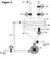
- FIG. 1 there is shown a device for sodium treatment of liquid hydrocarbons for the purpose of purification, desulfurization and reducing of aromatic compounds.
- Liquid hydrocarbons which should be anhydrous and preferably purified from coarse impurities and non-molecularly bound impurities, have to be introduced through entry 1) in liquid state into the vessel 4).
- the liquids should be heated in the vessel 4) to the desired treatment temperature before the sodium input.
- sodium can be introduced through input sluice 2) into the vessel 4).
- fluid temperatures above 280°C should prevail before entering the sodium through input sluice 2) into the vessel 4).
- the hot fluid in the device then continuously flows from the lower part of the vessel 4) through pumping unit 7) through dispersing unit 8) through flow pipe 10) and through throttle valve 5), and is subjected to strong mechanical forces, high shear and adjustable pressure before returning at entry point 12) into vessel 4).
- the minimal, stoichiometric sodium amount required in ppm is equivalent to 1,5 times the ppm of the sulphur contained in the hydrocarbon liquid, but also depends on the treatment objective and possible other ingredients that could react with sodium.
- Sodium may be introduced into the device in solid or liquid state via the sodium input sluice 2), located at the upper part of the vessel 4).
- the entered sodium immediately participates in the circulation through the pump- and dispersing circuit 7) 8) 10) 5) 12) and is kept from this moment, together with the oil to be treated, continuesly in circulation and dispersing state throughout the entire treatment time.
- vessel 4 If oils in the range of middle distillate, boiling on from 160°C, are treated, vessel 4) has only to be kept under pressure of 4-6 bar, what is usually enough to maintain the oils in liquid state at treatment temperature, at 280°C.
- the pressure created by pumping unit 7) can be kept or can be adjusted to a desired value, until fluids return to the vessel 4).
- the liquids can be decompressed through valve 6) or valve 9) into a settling tank, into a centrifuge, or preferably into a distillation device, whereby heat previously supplied to the treatment process, can also be used for the distillation.
Landscapes
- Chemical & Material Sciences (AREA)
- Chemical Kinetics & Catalysis (AREA)
- Organic Chemistry (AREA)
- Oil, Petroleum & Natural Gas (AREA)
- Engineering & Computer Science (AREA)
- General Chemical & Material Sciences (AREA)
- Production Of Liquid Hydrocarbon Mixture For Refining Petroleum (AREA)
Claims (6)
- Verfahren zur Behandlung von flüssigen Kohlenwasserstoffen, bei dem eine Reinigung, Entschwefelung und Reduktion von aromatischen Verbindungen von flüssigen Kohlenwasserstoffen erreicht wird durch- Zirkulieren von flüssigen Kohlenwasserstoffen in einer Vorrichtung, die einen Behälter (4) beinhaltet, der in einem oberen Teil einen Eingang (1) und Druckschleuseneinlässe (11) für zu behandelnde flüssige Kohlenwasserstoffe und Druckschleuseneinlässe (3) für festes oder geschmolzenes metallisches Natrium und in einem unteren Bereich Druckschleusenauslässe (6, 9) für Flüssigkeiten und Reaktionsprodukte aufweist, mit einem angeschlossenen druckbeaufschlagbaren Pump- und Dispergierkreislauf, aufweisend mindestens eine Pumpeinheit (7) und mindestens eine Dispergiereinheit (8), ein die Dispergiereinheit (8) mit einem Wiedereintritt (12) in den Behälter (4) verbindendes Strömungsrohr (10) und ein kurz vor dem Wiedereintritt (12) in den Behälter (4) angeordneten Drosselventil (5),- Einleiten von zu behandelnden flüssigen Kohlenwasserstoffen durch den Eingang (1) in den Behälter (4) und,- Zugabe von metallischem Natrium bei Flüssigkeitstemperaturen von mehr als 100°C, vorzugsweise mehr als 240°C, am meisten bevorzugt mehr als 280°C,- anschließendes Durchleiten der natriumhaltigen Flüssigkeit durch die Pumpeinheit (7), um sie auf Werte zwischen 1-100 bar, vorzugsweise 5-50 bar, am meisten bevorzugt 25-35 bar, unter Druck zu setzen,- dann Durchleiten der natriumhaltigen, unter Druck stehenden Flüssigkeit durch eine Dispergiereinheit (8) mit hoher Scherung, um Natriumpartikel mit einer Größe von weniger als 2 Mikrometern zu bilden und diese Natriumpartikel gleichzeitig in der Kohlenwasserstoffflüssigkeit zu dispergieren, und- dann Durchleiten dieser Flüssigkeit mit den eingemischten Natriumpartikeln durch das Strömungsrohr (10), das die Dispergiereinheit (8) mit dem Wiedereintritt (12) verbindet, in den Behälter (4), und- durch Einstellen der Durchflussmenge im Strömungsrohr (10) mittels des Drosselventils (5) wird der angelegte Druck beibehalten und eine Verweilzeit im Strömungsrohr (10) von mindestens 2 Sekunden, vorzugsweise 15 Sekunden, besonders bevorzugt länger 30 Sekunden, eingestellt,wobei die Behandlungszeit der flüssigen Kohlenwasserstoffe in der Vorrichtung ab dem Zeitpunkt der Natriumzufuhr zwischen 2 und 120 Minuten, vorzugsweise zwischen 5 und 20 Minuten, beträgt.
- Verfahren nach Anspruch 1, wobei der an den Behälter angeschlossene Pump- und Dispergierkreislauf eine kombinierte Pump- und Dispergiereinheit aufweist, die mindestens ein Pumpenlaufrad und mindestens ein Rotor-Stator-Dispergiermodul aufweist, die auf derselben Welle montiert und im selben Gehäuse angeordnet sind, wobei das nachgeschaltete Strömungsrohr diese kombinierte Pump- und Dispergiereinheit mit dem Wiedereintritt in den Behälter verbindet, dessen Durchmesser und Länge so gewählt ist, dass durch Einstellen des kurz vor der Rücklaufstelle in den Behälter befindlichen Drosselventils die Verweilzeit für die durchströmende Flüssigkeit zwischen 2 und 300 Sekunden, vorzugsweise zwischen 10 und 120 Sekunden, besonders bevorzugt zwischen 40 und 80 Sekunden, eingestellt wird.
- Verfahren nach Anspruch 2, wobei Durchmesser und Größe des Pumpenlaufrads und Durchmesser und Größe der Rotor-Stator-Disperger-Kombination der kombinierten Pump- und Dispergiereinheiten, die sich in demselben Gehäuse befinden, so gewählt werden, dass bei einer Disperger-Rotordrehzahl, die für einen optimalen Dispergiereffekt erforderlich ist, das Pumpelement einen Druck zwischen 2 und 100 bar, vorzugsweise zwischen 10 und 40 bar, besonders bevorzugt zwischen 25 und 35 bar, liefert.
- Verfahren nach allen vorhergehenden Ansprüchen, wobei Pumpenantriebs-E-Motoren und Dispergierantriebs-E-Motoren mit Frequenzumrichtern ausgestattet sind, die an ein elektronisches Überwachungssystem angeschlossen sind, das auch den Druck im Pump- und Dispergierkreislauf und die Einstellungen des Drosselventils überwacht und damit den einstellbaren Druck und die Durchflussmengen im Pump- und Dispergierkreislauf erhält, steuert und aufrechterhält.
- Verfahren nach allen vorhergehenden Ansprüchen, wobei im Moment des Einführens von metallischem Natrium im Pump- und Dispergierkreislauf der Druck höher als 3 bar, vorzugsweise höher als 15 bar, am meisten bevorzugt höher als 20 bar, ist, die Temperaturen über 100°C, vorzugsweise höher als 240°C, am meisten bevorzugt höher als 280°C, liegen und die Verweilzeit für die durchfließende Flüssigkeit so eingestellt ist, dass sie länger als 2 Sekunden, vorzugsweise länger als 15 Sekunden, am meisten bevorzugt länger als 30 Sekunden, ist, um eine Reinigung, Entschwefelung und/oder Reduktion der aromatischen Verbindungen der flüssigen Kohlenwasserstoffe zu erreichen.
- Verfahren nach allen vorhergehenden Ansprüchen, wobei im Moment des Einführens von metallischem Natrium im Pump- und Dispergierkreislauf der Druck höher als 3 bar, vorzugsweise höher als 15 bar, am meisten bevorzugt höher als 30 bar, ist, die Temperaturen über 100°C, vorzugsweise höher als 240°C, am meisten bevorzugt höher als 320°C, sind und die Verweilzeit für die durchfließende Flüssigkeit so eingestellt wird, dass sie länger als 10 Sekunden, vorzugsweise länger als 30 Sekunden, am meisten bevorzugt länger als 60 Sekunden, ist, um eine Aufspaltung und Verkürzung der Kohlenwasserstoffmolekülketten von Öl mit einem Siedepunkt, der höher als der von Mitteldestillaten ist, zu erreichen, um sie in solche von Öl im Bereich von Mitteldestillaten umzuwandeln.
Priority Applications (1)
| Application Number | Priority Date | Filing Date | Title |
|---|---|---|---|
| EP24216322.8A EP4495210A3 (de) | 2018-03-05 | 2018-05-30 | Verfahren und vorrichtung zur behandlung von flüssigen kohlenwasserstoffen |
Applications Claiming Priority (2)
| Application Number | Priority Date | Filing Date | Title |
|---|---|---|---|
| AU2018201581A AU2018201581B2 (en) | 2018-03-05 | 2018-03-05 | Method and Device for Treatment of of Liquid Hydrocarbons |
| PCT/EP2018/064235 WO2019170263A1 (en) | 2018-03-05 | 2018-05-30 | Method and device for treatment of liquid hydrocarbons |
Related Child Applications (2)
| Application Number | Title | Priority Date | Filing Date |
|---|---|---|---|
| EP24216322.8A Division EP4495210A3 (de) | 2018-03-05 | 2018-05-30 | Verfahren und vorrichtung zur behandlung von flüssigen kohlenwasserstoffen |
| EP24216322.8A Division-Into EP4495210A3 (de) | 2018-03-05 | 2018-05-30 | Verfahren und vorrichtung zur behandlung von flüssigen kohlenwasserstoffen |
Publications (4)
| Publication Number | Publication Date |
|---|---|
| EP3762474A1 EP3762474A1 (de) | 2021-01-13 |
| EP3762474B1 true EP3762474B1 (de) | 2024-12-25 |
| EP3762474C0 EP3762474C0 (de) | 2024-12-25 |
| EP3762474B8 EP3762474B8 (de) | 2025-02-19 |
Family
ID=62631049
Family Applications (2)
| Application Number | Title | Priority Date | Filing Date |
|---|---|---|---|
| EP24216322.8A Pending EP4495210A3 (de) | 2018-03-05 | 2018-05-30 | Verfahren und vorrichtung zur behandlung von flüssigen kohlenwasserstoffen |
| EP18731749.0A Active EP3762474B8 (de) | 2018-03-05 | 2018-05-30 | Verfahren zur behandlung von flüssigen kohlenwasserstoffen |
Family Applications Before (1)
| Application Number | Title | Priority Date | Filing Date |
|---|---|---|---|
| EP24216322.8A Pending EP4495210A3 (de) | 2018-03-05 | 2018-05-30 | Verfahren und vorrichtung zur behandlung von flüssigen kohlenwasserstoffen |
Country Status (6)
| Country | Link |
|---|---|
| US (4) | US20200399545A1 (de) |
| EP (2) | EP4495210A3 (de) |
| AU (2) | AU2018201581B2 (de) |
| CA (1) | CA3093178A1 (de) |
| ES (1) | ES3013907T3 (de) |
| WO (1) | WO2019170263A1 (de) |
Families Citing this family (2)
| Publication number | Priority date | Publication date | Assignee | Title |
|---|---|---|---|---|
| AU2018201581B2 (en) * | 2018-03-05 | 2024-12-12 | Ecofuel Technologies Ltd | Method and Device for Treatment of of Liquid Hydrocarbons |
| CN112098261B (zh) * | 2020-08-03 | 2022-03-11 | 中国原子能科学研究院 | 一种用于高温高压下液体金属钠蒸发的装置及操作方法 |
Family Cites Families (6)
| Publication number | Priority date | Publication date | Assignee | Title |
|---|---|---|---|---|
| CA774540A (en) * | 1967-12-26 | National Distillers And Chemical Corporation | Continuous process for sodium dispersions | |
| GB759283A (en) | 1952-12-24 | 1956-10-17 | British Petroleum Co | Improvements relating to the refining of petroleum hydrocarbons |
| US3166492A (en) | 1960-12-13 | 1965-01-19 | Degussa | Desulfurization of hydrocarbons |
| CH595432A5 (en) * | 1974-09-13 | 1978-02-15 | Frank Barry Haskett | Removal of sulphur cpds. from oil fractions |
| BR112014023203A2 (pt) * | 2012-03-21 | 2020-06-30 | H R D Corporation | sistema para converter uma primeira substância em uma segunda substância, e, métodos para armazenamento de longo prazo de hélio-3, para converter hélio-4 em hélio-3 e para converter um primeiro elemento em um elemento diferente ou em um isótopo do primeiro elemento |
| AU2018201581B2 (en) * | 2018-03-05 | 2024-12-12 | Ecofuel Technologies Ltd | Method and Device for Treatment of of Liquid Hydrocarbons |
-
2018
- 2018-03-05 AU AU2018201581A patent/AU2018201581B2/en active Active
- 2018-05-30 US US16/977,024 patent/US20200399545A1/en not_active Abandoned
- 2018-05-30 WO PCT/EP2018/064235 patent/WO2019170263A1/en not_active Ceased
- 2018-05-30 ES ES18731749T patent/ES3013907T3/es active Active
- 2018-05-30 EP EP24216322.8A patent/EP4495210A3/de active Pending
- 2018-05-30 EP EP18731749.0A patent/EP3762474B8/de active Active
- 2018-05-30 CA CA3093178A patent/CA3093178A1/en active Pending
-
2023
- 2023-08-16 US US18/450,972 patent/US12043805B2/en active Active
-
2024
- 2024-06-20 US US18/749,322 patent/US12281264B2/en active Active
-
2025
- 2025-03-11 AU AU2025201757A patent/AU2025201757A1/en active Pending
- 2025-03-31 US US19/096,377 patent/US12540283B2/en active Active
Also Published As
| Publication number | Publication date |
|---|---|
| US20250230367A1 (en) | 2025-07-17 |
| AU2025201757A1 (en) | 2025-04-03 |
| AU2018201581B2 (en) | 2024-12-12 |
| EP4495210A3 (de) | 2025-04-09 |
| WO2019170263A1 (en) | 2019-09-12 |
| US12043805B2 (en) | 2024-07-23 |
| EP3762474B8 (de) | 2025-02-19 |
| US12281264B2 (en) | 2025-04-22 |
| EP4495210A2 (de) | 2025-01-22 |
| US20240417630A1 (en) | 2024-12-19 |
| AU2018201581A1 (en) | 2019-09-19 |
| CA3093178A1 (en) | 2019-09-12 |
| US20230392081A1 (en) | 2023-12-07 |
| EP3762474A1 (de) | 2021-01-13 |
| US12540283B2 (en) | 2026-02-03 |
| US20200399545A1 (en) | 2020-12-24 |
| EP3762474C0 (de) | 2024-12-25 |
| ES3013907T3 (en) | 2025-04-15 |
Similar Documents
| Publication | Publication Date | Title |
|---|---|---|
| US12540283B2 (en) | Method and device for treatment of liquid hydrocarbons | |
| KR102105575B1 (ko) | 석유로부터 금속을 제거하는 방법 | |
| AU746498B2 (en) | Process to upgrade crude oils by destruction of naphthenic acids, removal of sulfur and removal of salts | |
| EP3565871B1 (de) | Verfahren zur entasphaltierung von öl | |
| CA2707688C (en) | Process for the desulfurization of heavy oils and bitumens | |
| WO2011123383A1 (en) | Integrated hydrotreating and oxidative desulfurization process | |
| KR20130031367A (ko) | 원유 탈황 | |
| JP6117203B2 (ja) | 中間留分の選択的水素化処理方法 | |
| KR20000065147A (ko) | 오일/물/생촉매삼상의분리방법 | |
| HK40119343A (en) | Method and device for treatment of liquid hydrocarbons | |
| RU2685550C1 (ru) | Способ получения дизельных топлив с улучшенными низкотемпературными свойствами и уменьшенным содержанием серы и устройство для его реализации | |
| US20250059453A1 (en) | Hydrocarbon oils desulfurization by supercritical water hydrogenation process | |
| EP4555046A1 (de) | Verfahren und systeme zur veredelung von rohöl | |
| HK1135427B (en) | Treatment of crude oil fractions, fossil fuels, and prodcuts thereof | |
| HK1097566B (en) | Treatment of crude oil fractions, fossil fuels, and products thereof | |
| HK1097566A1 (en) | Treatment of crude oil fractions, fossil fuels, and products thereof | |
| WO2009070251A1 (en) | Desulfurization of petroleum streams utilizing a multi-ring aromatic alkali metal complex |
Legal Events
| Date | Code | Title | Description |
|---|---|---|---|
| STAA | Information on the status of an ep patent application or granted ep patent |
Free format text: STATUS: UNKNOWN |
|
| STAA | Information on the status of an ep patent application or granted ep patent |
Free format text: STATUS: THE INTERNATIONAL PUBLICATION HAS BEEN MADE |
|
| PUAI | Public reference made under article 153(3) epc to a published international application that has entered the european phase |
Free format text: ORIGINAL CODE: 0009012 |
|
| STAA | Information on the status of an ep patent application or granted ep patent |
Free format text: STATUS: REQUEST FOR EXAMINATION WAS MADE |
|
| 17P | Request for examination filed |
Effective date: 20200902 |
|
| AK | Designated contracting states |
Kind code of ref document: A1 Designated state(s): AL AT BE BG CH CY CZ DE DK EE ES FI FR GB GR HR HU IE IS IT LI LT LU LV MC MK MT NL NO PL PT RO RS SE SI SK SM TR |
|
| AX | Request for extension of the european patent |
Extension state: BA ME |
|
| DAV | Request for validation of the european patent (deleted) | ||
| DAX | Request for extension of the european patent (deleted) | ||
| RAP1 | Party data changed (applicant data changed or rights of an application transferred) |
Owner name: ECOFUEL TECHNOLOGIES LTD |
|
| STAA | Information on the status of an ep patent application or granted ep patent |
Free format text: STATUS: EXAMINATION IS IN PROGRESS |
|
| 17Q | First examination report despatched |
Effective date: 20211117 |
|
| REG | Reference to a national code |
Ref country code: DE Ref legal event code: R079 Free format text: PREVIOUS MAIN CLASS: C10G0029040000 Ipc: B01J0004000000 Ref country code: DE Ref legal event code: R079 Ref document number: 602018077909 Country of ref document: DE Free format text: PREVIOUS MAIN CLASS: C10G0029040000 Ipc: B01J0004000000 |
|
| GRAP | Despatch of communication of intention to grant a patent |
Free format text: ORIGINAL CODE: EPIDOSNIGR1 |
|
| STAA | Information on the status of an ep patent application or granted ep patent |
Free format text: STATUS: GRANT OF PATENT IS INTENDED |
|
| RIC1 | Information provided on ipc code assigned before grant |
Ipc: C10G 29/04 20060101ALI20240621BHEP Ipc: B01J 19/24 20060101ALI20240621BHEP Ipc: B01J 4/00 20060101AFI20240621BHEP |
|
| INTG | Intention to grant announced |
Effective date: 20240715 |
|
| GRAS | Grant fee paid |
Free format text: ORIGINAL CODE: EPIDOSNIGR3 |
|
| GRAA | (expected) grant |
Free format text: ORIGINAL CODE: 0009210 |
|
| STAA | Information on the status of an ep patent application or granted ep patent |
Free format text: STATUS: THE PATENT HAS BEEN GRANTED |
|
| GRAE | Information related to correction after decision to grant or after decision to maintain patent in amended form modified |
Free format text: ORIGINAL CODE: EPIDOSCCDEC |
|
| GRAT | Correction requested after decision to grant or after decision to maintain patent in amended form |
Free format text: ORIGINAL CODE: EPIDOSNCDEC |
|
| AK | Designated contracting states |
Kind code of ref document: B1 Designated state(s): AL AT BE BG CH CY CZ DE DK EE ES FI FR GB GR HR HU IE IS IT LI LT LU LV MC MK MT NL NO PL PT RO RS SE SI SK SM TR |
|
| REG | Reference to a national code |
Ref country code: GB Ref legal event code: FG4D |
|
| REG | Reference to a national code |
Ref country code: CH Ref legal event code: EP |
|
| RAP4 | Party data changed (patent owner data changed or rights of a patent transferred) |
Owner name: ECOFUEL TECHNOLOGIES LTD |
|
| REG | Reference to a national code |
Ref country code: DE Ref legal event code: R096 Ref document number: 602018077909 Country of ref document: DE |
|
| REG | Reference to a national code |
Ref country code: DE Ref legal event code: R081 Ref document number: 602018077909 Country of ref document: DE Owner name: ECOFUEL TECHNOLOGIES LTD, MT Free format text: FORMER OWNER: ECOFUEL TECHNOLOGIES LTD, MALTA, MT |
|
| REG | Reference to a national code |
Ref country code: IE Ref legal event code: FG4D |
|
| REG | Reference to a national code |
Ref country code: CH Ref legal event code: PK Free format text: BERICHTIGUNG B8 |
|
| U01 | Request for unitary effect filed |
Effective date: 20250107 |
|
| U07 | Unitary effect registered |
Designated state(s): AT BE BG DE DK EE FI FR IT LT LU LV MT NL PT RO SE SI Effective date: 20250115 |
|
| PG25 | Lapsed in a contracting state [announced via postgrant information from national office to epo] |
Ref country code: HR Free format text: LAPSE BECAUSE OF FAILURE TO SUBMIT A TRANSLATION OF THE DESCRIPTION OR TO PAY THE FEE WITHIN THE PRESCRIBED TIME-LIMIT Effective date: 20241225 |
|
| REG | Reference to a national code |
Ref country code: ES Ref legal event code: FG2A Ref document number: 3013907 Country of ref document: ES Kind code of ref document: T3 Effective date: 20250415 |
|
| PG25 | Lapsed in a contracting state [announced via postgrant information from national office to epo] |
Ref country code: NO Free format text: LAPSE BECAUSE OF FAILURE TO SUBMIT A TRANSLATION OF THE DESCRIPTION OR TO PAY THE FEE WITHIN THE PRESCRIBED TIME-LIMIT Effective date: 20250325 |
|
| PG25 | Lapsed in a contracting state [announced via postgrant information from national office to epo] |
Ref country code: GR Free format text: LAPSE BECAUSE OF FAILURE TO SUBMIT A TRANSLATION OF THE DESCRIPTION OR TO PAY THE FEE WITHIN THE PRESCRIBED TIME-LIMIT Effective date: 20250326 |
|
| PG25 | Lapsed in a contracting state [announced via postgrant information from national office to epo] |
Ref country code: RS Free format text: LAPSE BECAUSE OF FAILURE TO SUBMIT A TRANSLATION OF THE DESCRIPTION OR TO PAY THE FEE WITHIN THE PRESCRIBED TIME-LIMIT Effective date: 20250325 |
|
| U20 | Renewal fee for the european patent with unitary effect paid |
Year of fee payment: 8 Effective date: 20250516 |
|
| PG25 | Lapsed in a contracting state [announced via postgrant information from national office to epo] |
Ref country code: SM Free format text: LAPSE BECAUSE OF FAILURE TO SUBMIT A TRANSLATION OF THE DESCRIPTION OR TO PAY THE FEE WITHIN THE PRESCRIBED TIME-LIMIT Effective date: 20241225 |
|
| PG25 | Lapsed in a contracting state [announced via postgrant information from national office to epo] |
Ref country code: PL Free format text: LAPSE BECAUSE OF FAILURE TO SUBMIT A TRANSLATION OF THE DESCRIPTION OR TO PAY THE FEE WITHIN THE PRESCRIBED TIME-LIMIT Effective date: 20241225 |
|
| PGFP | Annual fee paid to national office [announced via postgrant information from national office to epo] |
Ref country code: GB Payment date: 20250522 Year of fee payment: 8 Ref country code: ES Payment date: 20250616 Year of fee payment: 8 |
|
| PG25 | Lapsed in a contracting state [announced via postgrant information from national office to epo] |
Ref country code: IS Free format text: LAPSE BECAUSE OF FAILURE TO SUBMIT A TRANSLATION OF THE DESCRIPTION OR TO PAY THE FEE WITHIN THE PRESCRIBED TIME-LIMIT Effective date: 20250425 |
|
| PGFP | Annual fee paid to national office [announced via postgrant information from national office to epo] |
Ref country code: CH Payment date: 20250601 Year of fee payment: 8 |
|
| PG25 | Lapsed in a contracting state [announced via postgrant information from national office to epo] |
Ref country code: SK Free format text: LAPSE BECAUSE OF FAILURE TO SUBMIT A TRANSLATION OF THE DESCRIPTION OR TO PAY THE FEE WITHIN THE PRESCRIBED TIME-LIMIT Effective date: 20241225 |
|
| PG25 | Lapsed in a contracting state [announced via postgrant information from national office to epo] |
Ref country code: CZ Free format text: LAPSE BECAUSE OF FAILURE TO SUBMIT A TRANSLATION OF THE DESCRIPTION OR TO PAY THE FEE WITHIN THE PRESCRIBED TIME-LIMIT Effective date: 20241225 |
|
| PLBE | No opposition filed within time limit |
Free format text: ORIGINAL CODE: 0009261 |
|
| STAA | Information on the status of an ep patent application or granted ep patent |
Free format text: STATUS: NO OPPOSITION FILED WITHIN TIME LIMIT |
|
| 26N | No opposition filed |
Effective date: 20250926 |
|
| PG25 | Lapsed in a contracting state [announced via postgrant information from national office to epo] |
Ref country code: MC Free format text: LAPSE BECAUSE OF FAILURE TO SUBMIT A TRANSLATION OF THE DESCRIPTION OR TO PAY THE FEE WITHIN THE PRESCRIBED TIME-LIMIT Effective date: 20241225 |
|
| PG25 | Lapsed in a contracting state [announced via postgrant information from national office to epo] |
Ref country code: IE Free format text: LAPSE BECAUSE OF NON-PAYMENT OF DUE FEES Effective date: 20250530 |