EP3762514B1 - Unité de fusion pour la production d'acier - Google Patents
Unité de fusion pour la production d'acier Download PDFInfo
- Publication number
- EP3762514B1 EP3762514B1 EP19709450.1A EP19709450A EP3762514B1 EP 3762514 B1 EP3762514 B1 EP 3762514B1 EP 19709450 A EP19709450 A EP 19709450A EP 3762514 B1 EP3762514 B1 EP 3762514B1
- Authority
- EP
- European Patent Office
- Prior art keywords
- furnace
- smelting
- side wall
- smelting unit
- melt
- Prior art date
- Legal status (The legal status is an assumption and is not a legal conclusion. Google has not performed a legal analysis and makes no representation as to the accuracy of the status listed.)
- Active
Links
Images
Classifications
-
- C—CHEMISTRY; METALLURGY
- C21—METALLURGY OF IRON
- C21C—PROCESSING OF PIG-IRON, e.g. REFINING, MANUFACTURE OF WROUGHT-IRON OR STEEL; TREATMENT IN MOLTEN STATE OF FERROUS ALLOYS
- C21C5/00—Manufacture of carbon-steel, e.g. plain mild steel, medium carbon steel or cast steel or stainless steel
- C21C5/04—Manufacture of hearth-furnace steel, e.g. Siemens-Martin steel
-
- C—CHEMISTRY; METALLURGY
- C21—METALLURGY OF IRON
- C21C—PROCESSING OF PIG-IRON, e.g. REFINING, MANUFACTURE OF WROUGHT-IRON OR STEEL; TREATMENT IN MOLTEN STATE OF FERROUS ALLOYS
- C21C5/00—Manufacture of carbon-steel, e.g. plain mild steel, medium carbon steel or cast steel or stainless steel
- C21C5/28—Manufacture of steel in the converter
-
- C—CHEMISTRY; METALLURGY
- C21—METALLURGY OF IRON
- C21C—PROCESSING OF PIG-IRON, e.g. REFINING, MANUFACTURE OF WROUGHT-IRON OR STEEL; TREATMENT IN MOLTEN STATE OF FERROUS ALLOYS
- C21C5/00—Manufacture of carbon-steel, e.g. plain mild steel, medium carbon steel or cast steel or stainless steel
- C21C5/28—Manufacture of steel in the converter
- C21C5/30—Regulating or controlling the blowing
- C21C5/32—Blowing from above
-
- C—CHEMISTRY; METALLURGY
- C21—METALLURGY OF IRON
- C21C—PROCESSING OF PIG-IRON, e.g. REFINING, MANUFACTURE OF WROUGHT-IRON OR STEEL; TREATMENT IN MOLTEN STATE OF FERROUS ALLOYS
- C21C5/00—Manufacture of carbon-steel, e.g. plain mild steel, medium carbon steel or cast steel or stainless steel
- C21C5/52—Manufacture of steel in electric furnaces
-
- C—CHEMISTRY; METALLURGY
- C21—METALLURGY OF IRON
- C21C—PROCESSING OF PIG-IRON, e.g. REFINING, MANUFACTURE OF WROUGHT-IRON OR STEEL; TREATMENT IN MOLTEN STATE OF FERROUS ALLOYS
- C21C5/00—Manufacture of carbon-steel, e.g. plain mild steel, medium carbon steel or cast steel or stainless steel
- C21C5/52—Manufacture of steel in electric furnaces
- C21C5/5211—Manufacture of steel in electric furnaces in an alternating current [AC] electric arc furnace
- C21C5/5217—Manufacture of steel in electric furnaces in an alternating current [AC] electric arc furnace equipped with burners or devices for injecting gas, i.e. oxygen, or pulverulent materials into the furnace
-
- F—MECHANICAL ENGINEERING; LIGHTING; HEATING; WEAPONS; BLASTING
- F27—FURNACES; KILNS; OVENS; RETORTS
- F27B—FURNACES, KILNS, OVENS OR RETORTS IN GENERAL; OPEN SINTERING OR LIKE APPARATUS
- F27B3/00—Hearth-type furnaces, e.g. of reverberatory type; Electric arc furnaces ; Tank furnaces
- F27B3/08—Hearth-type furnaces, e.g. of reverberatory type; Electric arc furnaces ; Tank furnaces heated electrically, with or without any other source of heat
- F27B3/085—Arc furnaces
-
- F—MECHANICAL ENGINEERING; LIGHTING; HEATING; WEAPONS; BLASTING
- F27—FURNACES; KILNS; OVENS; RETORTS
- F27B—FURNACES, KILNS, OVENS OR RETORTS IN GENERAL; OPEN SINTERING OR LIKE APPARATUS
- F27B3/00—Hearth-type furnaces, e.g. of reverberatory type; Electric arc furnaces ; Tank furnaces
- F27B3/10—Details, accessories or equipment, e.g. dust-collectors, specially adapted for hearth-type furnaces
- F27B3/22—Arrangements of air or gas supply devices
- F27B3/225—Oxygen blowing
-
- F—MECHANICAL ENGINEERING; LIGHTING; HEATING; WEAPONS; BLASTING
- F27—FURNACES; KILNS; OVENS; RETORTS
- F27D—DETAILS OR ACCESSORIES OF FURNACES, KILNS, OVENS OR RETORTS, IN SO FAR AS THEY ARE OF KINDS OCCURRING IN MORE THAN ONE KIND OF FURNACE
- F27D17/00—Arrangements for using waste heat; Arrangements for using, or disposing of, waste gases
- F27D17/30—Arrangements for extraction or collection of waste gases; Hoods therefor
- F27D17/302—Constructional details of ancillary components, e.g. waste gas conduits or seals
-
- C—CHEMISTRY; METALLURGY
- C21—METALLURGY OF IRON
- C21B—MANUFACTURE OF IRON OR STEEL
- C21B2100/00—Handling of exhaust gases produced during the manufacture of iron or steel
-
- Y—GENERAL TAGGING OF NEW TECHNOLOGICAL DEVELOPMENTS; GENERAL TAGGING OF CROSS-SECTIONAL TECHNOLOGIES SPANNING OVER SEVERAL SECTIONS OF THE IPC; TECHNICAL SUBJECTS COVERED BY FORMER USPC CROSS-REFERENCE ART COLLECTIONS [XRACs] AND DIGESTS
- Y02—TECHNOLOGIES OR APPLICATIONS FOR MITIGATION OR ADAPTATION AGAINST CLIMATE CHANGE
- Y02P—CLIMATE CHANGE MITIGATION TECHNOLOGIES IN THE PRODUCTION OR PROCESSING OF GOODS
- Y02P10/00—Technologies related to metal processing
- Y02P10/20—Recycling
Definitions
- the invention relates to an improved melting unit for steel production with a hearth part, an annular, water-cooled, refractory-lined cylindrical upper furnace, onto which a conical hat closing at the top, with openings for exhaust gas guidance, can be placed.
- Scrap is a recyclable material that can be used again and again to produce steel.
- the prices for scrap are subject to strong fluctuations.
- local availability is also a decisive factor in determining the respective price.
- the object of the present invention is to provide a melting unit that enables the flexible processing of a wide variety of feedstocks, even in solid and/or liquid aggregate states, and the tap-to-tap times taking into account different steel qualities using different raw materials while simultaneously reducing CO2 .
- the melting unit is designed both for operation without melting current (i.e. electrical energy input) and for operation with melting current and the operation of the melting unit can be changed by changing the furnace cover, wherein the conical furnace cover for operation without melting current has at least one opening through which at least one top lance for blowing in a process gas can be introduced into the upper furnace and the conical furnace cover for operation with melting current has at least one opening through which at least one graphite electrode can be introduced into the upper furnace and a plurality of side wall injectors are arranged radially around the cylindrical upper furnace in such a way that the top lance and the side wall injectors can be aligned in the working position with a melt level of a melt located in the hearth part for refining.
- the conical furnace cover for operation without melting current has at least one opening through which at least one top lance for blowing in a process gas can be introduced into the upper furnace
- the conical furnace cover for operation with melting current has at least one opening through which at least one graphite electrode can be introduced into the upper
- the melting unit according to the invention makes it possible to interrupt the environmentally harmful process with hot metal as a feedstock for a certain period of time, to gradually reduce it to zero and finally to enable the blast furnace to be shut down using the same melting plant.
- High demands on steel quality and steel purity can be made by using scrap and solid starting material instead of pig iron.
- proven technologies of the BOF converter and the electric arc furnace are combined in order to use the most efficient and flexible application options for different forms of energy.
- the melting unit according to the invention enables flexible material variation with a short set-up time for the furnace system.
- the top lance and the side wall injectors can be operated simultaneously and in a coordinated manner with coordinated volume flows.
- the furnace cover can be replaced so that at least one graphite electrode can be introduced into the hearth part of the melting unit.
- At least one graphite electrode and a maximum of three graphite electrodes can be introduced through the openings of the furnace lid of the melting unit for operation with melt current.
- Groups I - IV represent so-called virgin materials that do not contain any undesirable steel constituents (e.g. Cu, Cr and Ni). For a range of steels, it is necessary to use a certain proportion of these virgin materials in order to ensure the quality of the end product. The production of these materials is very energy-intensive and therefore places a heavy burden on the environment.
- Groups V - VII represent carbon steel scrap of different quality and different processing levels. Scrap is recycled material. Higher processing levels and lower chemical contamination lead to higher prices for this scrap.
- Group VIII represents all special materials that are used as input materials for steel production.
- the melting unit according to the invention all input materials can be used flexibly, as it can be operated in a similar way to a BOF.
- the proportion of scrap (cooling scrap) or another coolant can be reduced to around 15%.
- Oxygen is introduced using side wall lances and a top lance.
- the problem of the furnace vessel becoming fermented when using normal EAFs in injector mode alone, i.e. without electrical energy input, is avoided in the melting unit according to the invention by a modified furnace geometry and the combination of side wall injectors and top lance.
- the melting unit can be operated like a normal EAF. Conversion to EAF operation is straightforward and can be carried out between two campaigns.
- the melting unit can be designed differently for operation without melt current, i.e. without electrical energy input, and operation with melt current.
- points d. and f. are omitted.
- points b., c. and f. are repeated.
- the melting unit according to the invention can be used universally. If it is used without a melting stream to produce steel, it combines many of the advantages of a BOF with those of an EAF. Although the blowing rate is lower than with a BOF, very high productivity can be achieved because the idle times of the melting unit according to the invention are shorter than with a BOF.
- top lance and side wall injectors suppresses excessive splashing and thus prevents the vessel from becoming smeared. This is supported by the design of the lid area, which also prevents the bend area from becoming smeared. Between 10% and 50% of the gas required for refining (oxygen or suitable substituents) should be blown into the melt in the melting unit through the side wall injectors and 90% to 50% through the top lance.
- the melting unit according to the invention is operated with melt current (i.e. with different mixtures of metallic feedstocks)
- the vessel is replaced with a lid and the furnace can now be operated with electrodes.
- the furnace continues to be highly effective thanks to the side wall injectors.
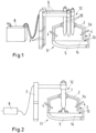
- the present melting unit 11 consists of a lower vessel 5 (hearth part) and an upper vessel 3, which are positively connected to one another.
- the lower vessel 5 is lined with refractory material and serves to hold a melt.
- the upper vessel 3 is assigned a water cooling system 3a.
- the upper vessel 3 can be covered with a hat/lid 2.
- the hat/lid 2 is assigned at least one opening 12 through which either melting electrodes, in particular graphite electrodes 10 (in this embodiment there are three graphite electrodes) or at least one top lance 1 can be introduced into the melting unit 11.
- the hat/lid 2 is, like the upper vessel 3, water-cooled.
- the graphite electrodes 10 and the top lance 1 are controlled via electrode support columns 7 and electrode arms 6 connected to them in order to be able to move them into and out of the melting unit 11 as required.
- the upper furnace 3 has a substantially round/cylindrical side wall 3a. Openings are assigned to the side wall 3a, running radially around the outside. Side wall injectors 4 can be introduced through the openings in the side wall 3a, which can then be aligned with a melt 14 to be treated in the lower furnace 5. The top lance 1 and the side wall injectors 4 are aligned in the working position with a melt level 13 of the melt 14 in the lower vessel/hearth section 5 for refining.
- the top lance 1 can be supplied with oxygen via a valve station (oxygen valve station) 8.
- the top lance 1 is controlled by the oxygen valve station 8 and operated according to the corresponding specifications.
- the graphite electrodes 10 are supplied with appropriate electrical energy by means of a transformer 9, as shown in Figure 1 is shown.
- side wall injectors 4 side lances
- the top lances 1 more than one top lance can be provided
- a gas usually oxygen
- side wall injectors 4 in the upper vessel 3 (or in the cylindrical side wall 3a) and one or more top lances 1 should always be operated together.
- This mode of operation should take place in an optimized mixing ratio of between 10% and 50% via the side injectors and 90% to 50% via the top lance 1 (or top lances).
- This mode of operation allows significantly more gas (oxygen) to be blown into the melt 14 per unit of time in a small melting unit 11 without significantly more splashes occurring.
Landscapes
- Engineering & Computer Science (AREA)
- Chemical & Material Sciences (AREA)
- Mechanical Engineering (AREA)
- General Engineering & Computer Science (AREA)
- Manufacturing & Machinery (AREA)
- Materials Engineering (AREA)
- Metallurgy (AREA)
- Organic Chemistry (AREA)
- Environmental & Geological Engineering (AREA)
- Vertical, Hearth, Or Arc Furnaces (AREA)
Claims (7)
- Installation de fusion (11) pour la production d'acier avec une partie inférieure de four / foyer (5) revêtue de matériaux réfractaires avec un trou de coulée au fond, une partie supérieure de four (3) essentiellement cylindrique, refroidie par eau, sur laquelle un couvercle de four conique (2), se terminant vers le haut et doté d'une buse d'évacuation des gaz spécialement conçue, peut être placé, caractérisée en ce que l'installation de fusion (11) est conçue à la fois pour fonctionner sans courant de fusion (c'est-à-dire sans apport d'énergie électrique) et pour fonctionner avec un courant de fusion, et que le mode de fonctionnement de l'installation de fusion (11) peut être modifié par le changement du couvercle de four (2), le couvercle de four conique (2) ayant au moins une ouverture (12) pour l'introduction d'au moins une lance supérieure (1) pour l'injection d'un gaz de processus dans la partie supérieure du four (3) et le couvercle de four conique (2) ayant au moins une ouverture (12) pour l'introduction d'au moins une électrode en graphite (10) dans la partie supérieure du four (3), et dans la partie supérieure du four (3) cylindrique une pluralité d'injecteurs latéraux (4) sont disposés de manière radiale et périphérique de sorte que la lance supérieure (1) et les injecteurs latéraux (4) puissent être alignés en position de travail sur un miroir de fusion (13) d'un métal en fusion (14) se trouvant dans la partie inférieure du four / foyer (5) pour l'affinage.
- Installation de fusion pour la production d'acier selon la revendication 1, caractérisée en ce que pour supprimer les éclaboussures fortes de fusion et de laitier et ainsi éviter les dommages à l'installation de fusion (11) et en particulier à la partie supérieure du four (3), la lance supérieure (1) et les injecteurs latéraux (4) peuvent être actionnés simultanément et avec des débits volumiques coordonnés les uns avec les autres.
- Installation de fusion pour la production d'acier selon la revendication 1, caractérisée en ce que pour le mode de fonctionnement avec courant de fusion, où différents mélanges de matières premières métalliques sont présents dans l'installation de fusion (11), le couvercle de four (2) est interchangeable, de sorte qu'au moins une électrode en graphite (10) peut être introduite dans la partie inférieure du four (5).
- Installation de fusion pour la production d'acier selon la revendication 3, caractérisée en ce que par les ouvertures (12) du couvercle de four (2) pour le mode de fonctionnement avec courant de fusion, au moins une électrode en graphite (10) peut être introduite et jusqu'à trois électrodes en graphite (10) peuvent être introduites.
- Installation de fusion pour la production d'acier selon la revendication 1 ou 2, caractérisée en ce que, avec une utilisation optimale des injecteurs latéraux (4) et de la lance supérieure (1), entre 10 % et 50 % du gaz nécessaire à l'affinage peut être injecté par les injecteurs latéraux (4) et entre 90 % et 50 % par la lance supérieure (1), simultanément et de manière coordonnée, dans le métal en fusion (14) se trouvant dans l'installation de fusion (11).
- Installation de fusion pour la production d'acier selon la revendication 5, caractérisée en ce que le rapport de mélange optimal entre la lance supérieure (1) et les injecteurs latéraux (4) permet de réduire les éclaboussures de fusion et de laitier, et ainsi de diminuer les dommages à la partie supérieure du four (3).
- Installation de fusion pour la production d'acier selon une ou plusieurs des revendications précédentes 1 à 6, caractérisée en ce que le couvercle de four (2) est associé à un coude de four spécialement formé et incliné, dont la section transversale est adaptée aux conditions de processus de manière à ce qu'une vitesse maximale de l'écoulement des gaz d'échappement générés lors de l'affinage de 50 m/s ne puisse être dépassée.
Applications Claiming Priority (2)
| Application Number | Priority Date | Filing Date | Title |
|---|---|---|---|
| DE102018203279 | 2018-03-06 | ||
| PCT/EP2019/055408 WO2019170650A1 (fr) | 2018-03-06 | 2019-03-05 | Unité de fusion pour la production d'acier |
Publications (2)
| Publication Number | Publication Date |
|---|---|
| EP3762514A1 EP3762514A1 (fr) | 2021-01-13 |
| EP3762514B1 true EP3762514B1 (fr) | 2024-08-14 |
Family
ID=67701793
Family Applications (1)
| Application Number | Title | Priority Date | Filing Date |
|---|---|---|---|
| EP19709450.1A Active EP3762514B1 (fr) | 2018-03-06 | 2019-03-05 | Unité de fusion pour la production d'acier |
Country Status (7)
| Country | Link |
|---|---|
| US (1) | US11549156B2 (fr) |
| EP (1) | EP3762514B1 (fr) |
| KR (1) | KR20200119325A (fr) |
| CN (1) | CN111801431A (fr) |
| DE (1) | DE102019105498A1 (fr) |
| ES (1) | ES2991440T3 (fr) |
| WO (1) | WO2019170650A1 (fr) |
Cited By (1)
| Publication number | Priority date | Publication date | Assignee | Title |
|---|---|---|---|---|
| US20240125553A1 (en) * | 2021-06-28 | 2024-04-18 | Safe Flow Llc | Emergency cooling-water vacuum system and method |
Families Citing this family (2)
| Publication number | Priority date | Publication date | Assignee | Title |
|---|---|---|---|---|
| DE102021214227A1 (de) * | 2021-12-13 | 2023-06-15 | Sms Group Gmbh | Schmelzaggregat zur Stahlerzeugung mit einem Abstichgewicht zwischen 60 t und 350 t |
| EP4545655A1 (fr) * | 2023-10-27 | 2025-04-30 | ThyssenKrupp Steel Europe AG | Procédé de production d'acier dans un ensemble d'installations |
Family Cites Families (16)
| Publication number | Priority date | Publication date | Assignee | Title |
|---|---|---|---|---|
| US3955964A (en) * | 1971-08-30 | 1976-05-11 | Koppers Company, Inc. | Process for making steel |
| US3812275A (en) * | 1973-02-26 | 1974-05-21 | Pennsylvania Engineering Corp | Steel production method and apparatus |
| JP2895247B2 (ja) * | 1991-01-11 | 1999-05-24 | 川崎製鉄株式会社 | 製鋼炉の操業方法 |
| DE4138120A1 (de) * | 1991-11-19 | 1993-05-27 | Fuchs Technology Ag | Einschmelzaggregat mit ofenwiege |
| AT396942B (de) * | 1991-12-16 | 1993-12-27 | Voest Alpine Ind Anlagen | Verfahren zum herstellen von metallschmelzen, insbesondere stahlschmelzen |
| DE4445209C2 (de) * | 1994-12-17 | 1999-01-21 | Schloemann Siemag Ag | Verfahren und Vorrichtung zum Betreiben eines Doppelgefäß-Lichtbogenofens |
| JPH08233466A (ja) * | 1995-02-27 | 1996-09-13 | Nippon Steel Corp | 転炉型操業と電炉型操業が可能な精錬炉 |
| DE19509285C2 (de) * | 1995-03-15 | 1997-03-20 | Gutehoffnungshuette Man | Schmelzgefäßanlage |
| DE10115779A1 (de) * | 2000-10-18 | 2002-04-25 | Sms Demag Ag | Verfahren zur Erzeugung nichtrostender Stähle, insbesondere chrom- und chromnickelhaltiger Edelstähle |
| DE10344198B4 (de) * | 2003-09-22 | 2006-08-03 | Ispat Industries Ltd., Taluka-Pen | Verfahren und Anlage zum Erhöhen der Produktivität beim Stahlherstellen |
| US7717976B2 (en) * | 2004-12-14 | 2010-05-18 | L&P Property Management Company | Method for making strain aging resistant steel |
| US8562713B2 (en) * | 2011-05-27 | 2013-10-22 | A. Finkl & Sons Co. | Flexible minimum energy utilization electric arc furnace system and processes for making steel products |
| DE102011087065A1 (de) * | 2011-11-24 | 2013-05-29 | Sms Siemag Ag | Elektrolichtbogenofen und Verfahren zu seinem Betrieb |
| DE102015105307A1 (de) | 2015-04-08 | 2016-10-13 | Sms Group Gmbh | Konverter |
| DE102015110674A1 (de) | 2015-07-02 | 2017-01-05 | Sms Group Gmbh | Umbausystem für einen Elektrolichtbogenofen (EAF) |
| US20170280519A1 (en) * | 2016-03-25 | 2017-09-28 | Air Liquide Industrial U.S. Lp | Inert gas blanketing of electrodes in an electric arc furnace |
-
2019
- 2019-03-05 ES ES19709450T patent/ES2991440T3/es active Active
- 2019-03-05 WO PCT/EP2019/055408 patent/WO2019170650A1/fr not_active Ceased
- 2019-03-05 DE DE102019105498.2A patent/DE102019105498A1/de not_active Withdrawn
- 2019-03-05 EP EP19709450.1A patent/EP3762514B1/fr active Active
- 2019-03-05 KR KR1020207026548A patent/KR20200119325A/ko not_active Ceased
- 2019-03-05 US US16/978,378 patent/US11549156B2/en active Active
- 2019-03-05 CN CN201980016940.0A patent/CN111801431A/zh active Pending
Cited By (1)
| Publication number | Priority date | Publication date | Assignee | Title |
|---|---|---|---|---|
| US20240125553A1 (en) * | 2021-06-28 | 2024-04-18 | Safe Flow Llc | Emergency cooling-water vacuum system and method |
Also Published As
| Publication number | Publication date |
|---|---|
| RU2020128146A (ru) | 2022-04-06 |
| US20210040573A1 (en) | 2021-02-11 |
| BR112020018110A2 (pt) | 2020-12-22 |
| WO2019170650A1 (fr) | 2019-09-12 |
| RU2020128146A3 (fr) | 2022-04-06 |
| DE102019105498A1 (de) | 2019-09-12 |
| CN111801431A (zh) | 2020-10-20 |
| KR20200119325A (ko) | 2020-10-19 |
| ES2991440T3 (es) | 2024-12-03 |
| US11549156B2 (en) | 2023-01-10 |
| EP3762514A1 (fr) | 2021-01-13 |
Similar Documents
| Publication | Publication Date | Title |
|---|---|---|
| WO1999000522A1 (fr) | Installation et dispositif pour la production de metal en fusion | |
| EP1627084B1 (fr) | Procede de recuperation de scories | |
| EP0820528B1 (fr) | Procede et installation de production de fontes en fer selon le procede de fusion en zones multiples | |
| EP1304391B1 (fr) | Procede de production d'une masse metallique en fusion en utilisant une lance multifunction | |
| EP0717115B1 (fr) | Procédé et installation pour opérer un four à arc à deux cuves | |
| EP0657549A1 (fr) | Procédé de production d'une fonte d'acier | |
| EP0784708B1 (fr) | Procede et dispositif de production en une seule etape de fer liquide par fusion electrique et non electrique | |
| DE102019105498A1 (de) | Schmelzaggregat zur Stahlerzeugung | |
| EP1481101B1 (fr) | Procede et dispositif de production d'acier en continu faisant appel a des matieres de charge metalliques | |
| EP3317602B1 (fr) | Convertisseur à l'oxygène adapté à partir d'un four à arc électrique | |
| EP1492893B1 (fr) | Procede et installation pour produire de l'acier inoxydable, notamment de l'acier fin renfermant du chrome ou du nickel-chrome | |
| EP1228251B1 (fr) | Procede et dispositif pour faire fondre un materiau contenant du metal sous forme de fines particules, tel que de l'eponge de fer | |
| KR20230167924A (ko) | 전기로 | |
| DE10344198B4 (de) | Verfahren und Anlage zum Erhöhen der Produktivität beim Stahlherstellen | |
| EP0663450B1 (fr) | Procédé et four à arc électrique avec électrodes pivotantes pour la production de fer en fusion | |
| EP0663579B1 (fr) | Procédé et installation pour la production de fer en fusion dans un four à cuve | |
| Prietl et al. | The evaluation of refractory linings thermo-mechanical properties | |
| DE102021214227A1 (de) | Schmelzaggregat zur Stahlerzeugung mit einem Abstichgewicht zwischen 60 t und 350 t | |
| DE19545831A1 (de) | Doppelgefäß-Lichtbogenofen | |
| DE4404313C2 (de) | Verfahren zum Aufschmelzen und Behandeln von Metallen und Anlage zur Durchführung des Verfahrens | |
| WO2005098053A2 (fr) | Procede et dispositif pour produire ou augmenter la production annuelle d'acier produit en masse ou de produits d'acier de qualite, dans une installation a deux cuves | |
| DE102005007655A1 (de) | Ofenanlage und Verfahren zum Einschmelzen von metallischen oder metallhaltigen Einsatzstoffen | |
| Strohmeier et al. | The production of steel for flat products in large ultra-high-powered furnaces | |
| EP1630238A1 (fr) | Procédé pour la récupération d'éléments métalliques a partir de laitiers d'oxydes métalliques | |
| Vallomy | Energy and environment make Consteel the choice in USA and Japan |
Legal Events
| Date | Code | Title | Description |
|---|---|---|---|
| STAA | Information on the status of an ep patent application or granted ep patent |
Free format text: STATUS: UNKNOWN |
|
| STAA | Information on the status of an ep patent application or granted ep patent |
Free format text: STATUS: THE INTERNATIONAL PUBLICATION HAS BEEN MADE |
|
| PUAI | Public reference made under article 153(3) epc to a published international application that has entered the european phase |
Free format text: ORIGINAL CODE: 0009012 |
|
| STAA | Information on the status of an ep patent application or granted ep patent |
Free format text: STATUS: REQUEST FOR EXAMINATION WAS MADE |
|
| 17P | Request for examination filed |
Effective date: 20201006 |
|
| AK | Designated contracting states |
Kind code of ref document: A1 Designated state(s): AL AT BE BG CH CY CZ DE DK EE ES FI FR GB GR HR HU IE IS IT LI LT LU LV MC MK MT NL NO PL PT RO RS SE SI SK SM TR |
|
| AX | Request for extension of the european patent |
Extension state: BA ME |
|
| DAV | Request for validation of the european patent (deleted) | ||
| DAX | Request for extension of the european patent (deleted) | ||
| P01 | Opt-out of the competence of the unified patent court (upc) registered |
Effective date: 20230707 |
|
| REG | Reference to a national code |
Ref country code: DE Free format text: PREVIOUS MAIN CLASS: C21C0005520000 Ref country code: DE Ref legal event code: R079 Ref document number: 502019011890 Country of ref document: DE Free format text: PREVIOUS MAIN CLASS: C21C0005520000 Ipc: F27B0003080000 |
|
| GRAP | Despatch of communication of intention to grant a patent |
Free format text: ORIGINAL CODE: EPIDOSNIGR1 |
|
| STAA | Information on the status of an ep patent application or granted ep patent |
Free format text: STATUS: GRANT OF PATENT IS INTENDED |
|
| RIC1 | Information provided on ipc code assigned before grant |
Ipc: C21C 5/32 20060101ALI20240318BHEP Ipc: C21C 5/28 20060101ALI20240318BHEP Ipc: F27B 3/22 20060101ALI20240318BHEP Ipc: C21C 5/52 20060101ALI20240318BHEP Ipc: F27B 3/08 20060101AFI20240318BHEP |
|
| INTG | Intention to grant announced |
Effective date: 20240409 |
|
| RIN1 | Information on inventor provided before grant (corrected) |
Inventor name: ODENTHAL, HANS-JUERGEN Inventor name: HENKEL, THOMAS Inventor name: SCHUERING, ANDREAS Inventor name: STARKE, PETER |
|
| GRAS | Grant fee paid |
Free format text: ORIGINAL CODE: EPIDOSNIGR3 |
|
| GRAA | (expected) grant |
Free format text: ORIGINAL CODE: 0009210 |
|
| STAA | Information on the status of an ep patent application or granted ep patent |
Free format text: STATUS: THE PATENT HAS BEEN GRANTED |
|
| AK | Designated contracting states |
Kind code of ref document: B1 Designated state(s): AL AT BE BG CH CY CZ DE DK EE ES FI FR GB GR HR HU IE IS IT LI LT LU LV MC MK MT NL NO PL PT RO RS SE SI SK SM TR |
|
| REG | Reference to a national code |
Ref country code: GB Ref legal event code: FG4D Free format text: NOT ENGLISH |
|
| REG | Reference to a national code |
Ref country code: CH Ref legal event code: EP |
|
| RAP4 | Party data changed (patent owner data changed or rights of a patent transferred) |
Owner name: SMS GROUP GMBH |
|
| REG | Reference to a national code |
Ref country code: DE Ref legal event code: R096 Ref document number: 502019011890 Country of ref document: DE |
|
| REG | Reference to a national code |
Ref country code: IE Ref legal event code: FG4D Free format text: LANGUAGE OF EP DOCUMENT: GERMAN |
|
| REG | Reference to a national code |
Ref country code: DE Ref legal event code: R081 Ref document number: 502019011890 Country of ref document: DE Owner name: SMS GROUP GMBH, DE Free format text: FORMER OWNER: SMS GROUP GMBH, 40237 DUESSELDORF, DE |
|
| REG | Reference to a national code |
Ref country code: ES Ref legal event code: FG2A Ref document number: 2991440 Country of ref document: ES Kind code of ref document: T3 Effective date: 20241203 |
|
| REG | Reference to a national code |
Ref country code: LT Ref legal event code: MG9D |
|
| REG | Reference to a national code |
Ref country code: NL Ref legal event code: MP Effective date: 20240814 |
|
| PG25 | Lapsed in a contracting state [announced via postgrant information from national office to epo] |
Ref country code: NO Free format text: LAPSE BECAUSE OF FAILURE TO SUBMIT A TRANSLATION OF THE DESCRIPTION OR TO PAY THE FEE WITHIN THE PRESCRIBED TIME-LIMIT Effective date: 20241114 |
|
| PG25 | Lapsed in a contracting state [announced via postgrant information from national office to epo] |
Ref country code: NL Free format text: LAPSE BECAUSE OF FAILURE TO SUBMIT A TRANSLATION OF THE DESCRIPTION OR TO PAY THE FEE WITHIN THE PRESCRIBED TIME-LIMIT Effective date: 20240814 Ref country code: FI Free format text: LAPSE BECAUSE OF FAILURE TO SUBMIT A TRANSLATION OF THE DESCRIPTION OR TO PAY THE FEE WITHIN THE PRESCRIBED TIME-LIMIT Effective date: 20240814 Ref country code: PL Free format text: LAPSE BECAUSE OF FAILURE TO SUBMIT A TRANSLATION OF THE DESCRIPTION OR TO PAY THE FEE WITHIN THE PRESCRIBED TIME-LIMIT Effective date: 20240814 Ref country code: GR Free format text: LAPSE BECAUSE OF FAILURE TO SUBMIT A TRANSLATION OF THE DESCRIPTION OR TO PAY THE FEE WITHIN THE PRESCRIBED TIME-LIMIT Effective date: 20241115 Ref country code: PT Free format text: LAPSE BECAUSE OF FAILURE TO SUBMIT A TRANSLATION OF THE DESCRIPTION OR TO PAY THE FEE WITHIN THE PRESCRIBED TIME-LIMIT Effective date: 20241216 |
|
| PG25 | Lapsed in a contracting state [announced via postgrant information from national office to epo] |
Ref country code: BG Free format text: LAPSE BECAUSE OF FAILURE TO SUBMIT A TRANSLATION OF THE DESCRIPTION OR TO PAY THE FEE WITHIN THE PRESCRIBED TIME-LIMIT Effective date: 20240814 |
|
| PG25 | Lapsed in a contracting state [announced via postgrant information from national office to epo] |
Ref country code: LV Free format text: LAPSE BECAUSE OF FAILURE TO SUBMIT A TRANSLATION OF THE DESCRIPTION OR TO PAY THE FEE WITHIN THE PRESCRIBED TIME-LIMIT Effective date: 20240814 |
|
| PG25 | Lapsed in a contracting state [announced via postgrant information from national office to epo] |
Ref country code: IS Free format text: LAPSE BECAUSE OF FAILURE TO SUBMIT A TRANSLATION OF THE DESCRIPTION OR TO PAY THE FEE WITHIN THE PRESCRIBED TIME-LIMIT Effective date: 20241214 |
|
| PG25 | Lapsed in a contracting state [announced via postgrant information from national office to epo] |
Ref country code: HR Free format text: LAPSE BECAUSE OF FAILURE TO SUBMIT A TRANSLATION OF THE DESCRIPTION OR TO PAY THE FEE WITHIN THE PRESCRIBED TIME-LIMIT Effective date: 20240814 |
|
| PG25 | Lapsed in a contracting state [announced via postgrant information from national office to epo] |
Ref country code: RS Free format text: LAPSE BECAUSE OF FAILURE TO SUBMIT A TRANSLATION OF THE DESCRIPTION OR TO PAY THE FEE WITHIN THE PRESCRIBED TIME-LIMIT Effective date: 20241114 |
|
| PG25 | Lapsed in a contracting state [announced via postgrant information from national office to epo] |
Ref country code: RS Free format text: LAPSE BECAUSE OF FAILURE TO SUBMIT A TRANSLATION OF THE DESCRIPTION OR TO PAY THE FEE WITHIN THE PRESCRIBED TIME-LIMIT Effective date: 20241114 Ref country code: PT Free format text: LAPSE BECAUSE OF FAILURE TO SUBMIT A TRANSLATION OF THE DESCRIPTION OR TO PAY THE FEE WITHIN THE PRESCRIBED TIME-LIMIT Effective date: 20241216 Ref country code: PL Free format text: LAPSE BECAUSE OF FAILURE TO SUBMIT A TRANSLATION OF THE DESCRIPTION OR TO PAY THE FEE WITHIN THE PRESCRIBED TIME-LIMIT Effective date: 20240814 Ref country code: NO Free format text: LAPSE BECAUSE OF FAILURE TO SUBMIT A TRANSLATION OF THE DESCRIPTION OR TO PAY THE FEE WITHIN THE PRESCRIBED TIME-LIMIT Effective date: 20241114 Ref country code: NL Free format text: LAPSE BECAUSE OF FAILURE TO SUBMIT A TRANSLATION OF THE DESCRIPTION OR TO PAY THE FEE WITHIN THE PRESCRIBED TIME-LIMIT Effective date: 20240814 Ref country code: LV Free format text: LAPSE BECAUSE OF FAILURE TO SUBMIT A TRANSLATION OF THE DESCRIPTION OR TO PAY THE FEE WITHIN THE PRESCRIBED TIME-LIMIT Effective date: 20240814 Ref country code: IS Free format text: LAPSE BECAUSE OF FAILURE TO SUBMIT A TRANSLATION OF THE DESCRIPTION OR TO PAY THE FEE WITHIN THE PRESCRIBED TIME-LIMIT Effective date: 20241214 Ref country code: HR Free format text: LAPSE BECAUSE OF FAILURE TO SUBMIT A TRANSLATION OF THE DESCRIPTION OR TO PAY THE FEE WITHIN THE PRESCRIBED TIME-LIMIT Effective date: 20240814 Ref country code: GR Free format text: LAPSE BECAUSE OF FAILURE TO SUBMIT A TRANSLATION OF THE DESCRIPTION OR TO PAY THE FEE WITHIN THE PRESCRIBED TIME-LIMIT Effective date: 20241115 Ref country code: FI Free format text: LAPSE BECAUSE OF FAILURE TO SUBMIT A TRANSLATION OF THE DESCRIPTION OR TO PAY THE FEE WITHIN THE PRESCRIBED TIME-LIMIT Effective date: 20240814 Ref country code: BG Free format text: LAPSE BECAUSE OF FAILURE TO SUBMIT A TRANSLATION OF THE DESCRIPTION OR TO PAY THE FEE WITHIN THE PRESCRIBED TIME-LIMIT Effective date: 20240814 |
|
| PG25 | Lapsed in a contracting state [announced via postgrant information from national office to epo] |
Ref country code: SM Free format text: LAPSE BECAUSE OF FAILURE TO SUBMIT A TRANSLATION OF THE DESCRIPTION OR TO PAY THE FEE WITHIN THE PRESCRIBED TIME-LIMIT Effective date: 20240814 Ref country code: RO Free format text: LAPSE BECAUSE OF FAILURE TO SUBMIT A TRANSLATION OF THE DESCRIPTION OR TO PAY THE FEE WITHIN THE PRESCRIBED TIME-LIMIT Effective date: 20240814 Ref country code: DK Free format text: LAPSE BECAUSE OF FAILURE TO SUBMIT A TRANSLATION OF THE DESCRIPTION OR TO PAY THE FEE WITHIN THE PRESCRIBED TIME-LIMIT Effective date: 20240814 |
|
| PG25 | Lapsed in a contracting state [announced via postgrant information from national office to epo] |
Ref country code: EE Free format text: LAPSE BECAUSE OF FAILURE TO SUBMIT A TRANSLATION OF THE DESCRIPTION OR TO PAY THE FEE WITHIN THE PRESCRIBED TIME-LIMIT Effective date: 20240814 |
|
| PG25 | Lapsed in a contracting state [announced via postgrant information from national office to epo] |
Ref country code: CZ Free format text: LAPSE BECAUSE OF FAILURE TO SUBMIT A TRANSLATION OF THE DESCRIPTION OR TO PAY THE FEE WITHIN THE PRESCRIBED TIME-LIMIT Effective date: 20240814 |
|
| PG25 | Lapsed in a contracting state [announced via postgrant information from national office to epo] |
Ref country code: SK Free format text: LAPSE BECAUSE OF FAILURE TO SUBMIT A TRANSLATION OF THE DESCRIPTION OR TO PAY THE FEE WITHIN THE PRESCRIBED TIME-LIMIT Effective date: 20240814 |
|
| REG | Reference to a national code |
Ref country code: DE Ref legal event code: R097 Ref document number: 502019011890 Country of ref document: DE |
|
| PLBE | No opposition filed within time limit |
Free format text: ORIGINAL CODE: 0009261 |
|
| STAA | Information on the status of an ep patent application or granted ep patent |
Free format text: STATUS: NO OPPOSITION FILED WITHIN TIME LIMIT |
|
| PGFP | Annual fee paid to national office [announced via postgrant information from national office to epo] |
Ref country code: ES Payment date: 20250429 Year of fee payment: 7 |
|
| 26N | No opposition filed |
Effective date: 20250515 |
|
| PG25 | Lapsed in a contracting state [announced via postgrant information from national office to epo] |
Ref country code: SE Free format text: LAPSE BECAUSE OF FAILURE TO SUBMIT A TRANSLATION OF THE DESCRIPTION OR TO PAY THE FEE WITHIN THE PRESCRIBED TIME-LIMIT Effective date: 20240814 |
|
| PG25 | Lapsed in a contracting state [announced via postgrant information from national office to epo] |
Ref country code: MC Free format text: LAPSE BECAUSE OF FAILURE TO SUBMIT A TRANSLATION OF THE DESCRIPTION OR TO PAY THE FEE WITHIN THE PRESCRIBED TIME-LIMIT Effective date: 20240814 |
|
| REG | Reference to a national code |
Ref country code: CH Ref legal event code: H13 Free format text: ST27 STATUS EVENT CODE: U-0-0-H10-H13 (AS PROVIDED BY THE NATIONAL OFFICE) Effective date: 20251023 |
|
| PG25 | Lapsed in a contracting state [announced via postgrant information from national office to epo] |
Ref country code: LU Free format text: LAPSE BECAUSE OF NON-PAYMENT OF DUE FEES Effective date: 20250305 |
|
| GBPC | Gb: european patent ceased through non-payment of renewal fee |
Effective date: 20250305 |
|
| REG | Reference to a national code |
Ref country code: BE Ref legal event code: MM Effective date: 20250331 |
|
| PG25 | Lapsed in a contracting state [announced via postgrant information from national office to epo] |
Ref country code: GB Free format text: LAPSE BECAUSE OF NON-PAYMENT OF DUE FEES Effective date: 20250305 |
|
| PG25 | Lapsed in a contracting state [announced via postgrant information from national office to epo] |
Ref country code: FR Free format text: LAPSE BECAUSE OF NON-PAYMENT OF DUE FEES Effective date: 20250331 |
|
| PG25 | Lapsed in a contracting state [announced via postgrant information from national office to epo] |
Ref country code: BE Free format text: LAPSE BECAUSE OF NON-PAYMENT OF DUE FEES Effective date: 20250331 |
|
| PG25 | Lapsed in a contracting state [announced via postgrant information from national office to epo] |
Ref country code: CH Free format text: LAPSE BECAUSE OF NON-PAYMENT OF DUE FEES Effective date: 20250331 |
|
| PG25 | Lapsed in a contracting state [announced via postgrant information from national office to epo] |
Ref country code: IE Free format text: LAPSE BECAUSE OF NON-PAYMENT OF DUE FEES Effective date: 20250305 |
|
| PGFP | Annual fee paid to national office [announced via postgrant information from national office to epo] |
Ref country code: DE Payment date: 20260319 Year of fee payment: 8 |
|
| PGFP | Annual fee paid to national office [announced via postgrant information from national office to epo] |
Ref country code: AT Payment date: 20260320 Year of fee payment: 8 |
|
| PGFP | Annual fee paid to national office [announced via postgrant information from national office to epo] |
Ref country code: IT Payment date: 20260324 Year of fee payment: 8 |