EP3762620B1 - Liaison d'un élément à du verre - Google Patents
Liaison d'un élément à du verre Download PDFInfo
- Publication number
- EP3762620B1 EP3762620B1 EP19712627.9A EP19712627A EP3762620B1 EP 3762620 B1 EP3762620 B1 EP 3762620B1 EP 19712627 A EP19712627 A EP 19712627A EP 3762620 B1 EP3762620 B1 EP 3762620B1
- Authority
- EP
- European Patent Office
- Prior art keywords
- component
- panel
- compound
- zone
- opening
- Prior art date
- Legal status (The legal status is an assumption and is not a legal conclusion. Google has not performed a legal analysis and makes no representation as to the accuracy of the status listed.)
- Active
Links
Images


Classifications
-
- F—MECHANICAL ENGINEERING; LIGHTING; HEATING; WEAPONS; BLASTING
- F16—ENGINEERING ELEMENTS AND UNITS; GENERAL MEASURES FOR PRODUCING AND MAINTAINING EFFECTIVE FUNCTIONING OF MACHINES OR INSTALLATIONS; THERMAL INSULATION IN GENERAL
- F16B—DEVICES FOR FASTENING OR SECURING CONSTRUCTIONAL ELEMENTS OR MACHINE PARTS TOGETHER, e.g. NAILS, BOLTS, CIRCLIPS, CLAMPS, CLIPS OR WEDGES; JOINTS OR JOINTING
- F16B11/00—Connecting constructional elements or machine parts by sticking or pressing them together, e.g. cold pressure welding
- F16B11/006—Connecting constructional elements or machine parts by sticking or pressing them together, e.g. cold pressure welding by gluing
Definitions
- the present invention relates to the connecting of a component to a panel.
- the invention relates more particularly to a method for connecting a component to a glass panel.
- Glass panels are used in many sectors as part of a greater whole. For this purpose it is often necessary to connect components, these being parts or elements, to the glass panel. In many situations it is undesirable to provide a perforation in the glass for the purpose of mechanical connection to a component. It is also often undesirable to connect the component at the position of the edge of the glass.
- a glue is used to connect a component in a central zone of the glass without the provision of a perforation in glass. More specifically, the component is connected to the glass via adhesion.
- Each of documents EP0870933A2 , EP132980A2 and WO01/81774A1 relate to connecting of a component to a panel.
- EP0870933A2 discloses a method of producing a connection between two components in which a connecting part is adhesively bonded to a first component, and a second component is fitted, preferably clipped, to the connecting part, an adhesive is applied to the first component in the connection area, in that the connecting part is of strip-like or strand-like design and has a plurality of form-fitting apertures running through from the outside towards the first component and into which a casting compound is put in such a way that, on one side, it rests on the adhesive and, on the other side, covers the apertures on the outside, and in that the fitting of the second component to the connecting part is carried out after the casting compound has hardened.
- such a component is typically connected to a glass panel via a glue.
- the glue is applied between a connection side of the component and the panel.
- the connection side is typically held at a distance from the panel, for instance by spacers, in order to give the glue a sufficiently great thickness.
- the glass has to be cleaned of dirt, grease and dust to maximum extent, and typically also provided with a primer layer.
- the connection side of the component also has to be cleaned of dirt, grease and dust to maximum extent, and the connection side of the component also has to be provided with a primer layer.
- the material from which the component is manufactured it is further important for the material from which the component is manufactured to be compatible with the glue.
- This compatibility is necessary in order to realize a good bond between the glue and the component.
- This compatibility further has the result that, when a component is manufactured from an alternative material, a different glue and/or different primer has to be used. This greatly limits designers in the choice of material of the component. More specifically, components will typically have to be manufactured from more expensive materials in order to enable a good glueing.
- a further drawback of glueing the component to the glass panel is related to the drying time of the glue.
- the drying time of the glue which can typically amount to one or more hours, the panel with the component must be kept in conditioned circumstances.
- no external force should engage on the component during the drying process, because this may alter the position of the component relative to the panel. All these factors make connecting of a component to a glass plate complex and expensive.
- the invention provides for this purpose a method for connecting a component to a panel, wherein the component comprises a connection side which is positioned at a distance from the panel and wherein a compound is introduced between the connection side and the panel, characterized in that a zone is delimited between the connection side and the panel such that a physical barrier is formed for the compound, which zone has at least an opening in the connection side, and wherein a compound in liquid form is applied above the opening so as to flow through the opening and fill the zone, wherein above said opening a further zone is at least partially filled by the compound such that, after at least partial curing of the compound, the component is held mechanically by the compound.
- the component is connected to the panel via the cured compound.
- Any compound which has an adhesive force for the surface of the panel and which is in liquid form when applied is usable within the context of the present invention.
- the compound is adapted to bond to the panel via an adhesive force. More specifically, the compound is selected to bond with a predetermined adhesive force to a surface of the panel.
- the compound is further provided to hold the component mechanically. This is the result of the specific application of the compound in liquid form above an opening, wherein a zone below the opening and a zone above the opening are filled by the compound. During the curing the compound will form a volume below the opening which connects to the volume through the opening and to a volume above the opening.
- the adhesive bond between the component and the compound is not critical for the connection of the component to the panel, a designer has considerably more freedom when choosing the material of the component, and when choosing the material of the compound.
- an adhesive complementarity must always be sought between the material of the component and the compound, while this is no longer necessary according to the present method.
- the component can thereby be manufactured from a cheaper material or be manufactured from a material which can be shaped more easily and/or freely.
- the pretreatment steps of the component, which are necessary in the prior art to guarantee a good bond are no longer necessary. This considerably simplifies the method for connecting a component to a panel.
- any compound that has an adhesive complementarity with the surface to which the component is applied has to fill the zone between the connection side of the component and the surface of the panel as fully as possible when applied.
- the compound is for this purpose in liquid form when applied.
- the compound is preferably in hyperfluid form when applied.
- Such a hyperfluid material is typically applied in an open mould and is known to fill the mould easily and wholly, into its smallest openings. The hyperfluid material lies closely against the edges of the mould.
- the mould is formed by the panel and the component, more particularly by the zone between the connection side of the component and the surface of the panel.
- this zone is accessible by means of an opening in the connection side of the component.
- the liquid or hyperfluid compound can be applied through the opening and into the delimited zone.
- the liquid compound will fill the delimited zone as fully as possible.
- the hyperfluid material will also fill the opening, and the hyperfluid material will fill a further zone above the opening.
- Liquid and hyperfluid compounds with a short curing time of between several tens of seconds and several minutes are known. It will be apparent here to the skilled person that in this context curing time does not relate to full curing of the compound, but to curing to a point where the bond between compound and panel has occurred to sufficient extent to prevent undesired displacement of the component and to prevent undesired deformation of the compound, also referred to as time to handling strength. Such a short curing time is only possible because an adhesive bond with only one material is necessary, more specifically the material of the panel. In a prior art situation an adhesive bond has to take place with two typically different materials, which typically also requires considerably more time.
- a further advantage of the invention is therefore that the panel and the component can be connected considerably faster and without drying time, or with a less complicated conditioned drying time. This makes connecting of a component to a panel in an industrial context considerably more simple and inexpensive.
- the compound preferably has a dynamic viscosity, measured at a shear rate of 1/s, of lower than 35,000 mPa.s when it comes to lie on at least a part of the panel.
- This compound is known as a hyperfluid material.
- Such a hyperfluid material is typically applied in an open mould and is known to fill the mould easily and wholly, into its smallest openings. The hyperfluid material lies closely against the edges of the mould.
- the panel is preferably a glass panel.
- the invention was specifically developed in the context of the automobile sector, wherein components are attached to glass.
- a compound with a dynamic viscosity as defined in claim 1 is also already in use here for the purpose of forming an edge on a glass panel in order to further connect the glass panel to the bodywork of the vehicle.
- Using the same compound for the purpose of connecting a component to the glass panel further optimizes the process of preparing the glass for placing in the vehicle. This is because both the edges of the glass can be formed and the components can be glued to the glass in one pretreatment step.
- the zone is preferably delimited by the provision of an edge which extends all around the zone between the connection side and the panel in order to prevent the compound from flowing beyond the edge.
- the compound is hyperfluid, whereby it has the option and/or tendency to quickly flow out over a wide area.
- the edge By providing an edge around the zone the flow of the compound can be delimited. Because the edge is provided, the thickness of the zone can be optimized so as to achieve multiple effects.
- a first desired effect is that the zone is filled substantially wholly.
- a gradual filling of the zone can be achieved by making the zone sufficiently thick.
- a second effect relates to the compound mechanically holding the component when the compound is at least partially cured. By making the zone sufficiently thick the strength of the compound after curing, more specifically the mechanical resistance against tearing or breaking of the cured material, is sufficiently great to hold the component mechanically.
- the edge is preferably formed by a thickened portion on the connection side of the component.
- the thickened portion on the connection side of the component the component can already be provided during the design thereof with edges which delimit the zone.
- the glass can be provided with an upright edge, for instance by application of a silicone layer on the glass.
- the edge is preferably formed by a compressible material and the edge preferably has a thickness equal to or greater than the stated distance, such that tolerances in said distance are compensated for by the edge. Because the compound with which the zone is filled is in liquid form, and preferably in hyperfluid form, when applied, even a minuscule opening between the connection side and the glass panel is enough to create leakage of the compound out of the zone. This can be prevented by providing the edge with a compressible, i.e. an elastic or plastically deformable, material. The edge is then typically made slightly thicker than necessary for bridging the distance, such that the edge is compressed when the component is positioned relative to the panel. Compression of the edge will result in a guaranteed or at least better connection of the edge against the connection side and the panel, such that an undesired opening can be avoided.
- the method preferably further comprises of, during or after positioning of the component, orienting the panel with the component such that the opening is situated above the zone.
- orienting the panel with the component such that the opening is situated above the zone.
- application of the liquid or hyperfluid compound will be facilitated. This is because the compound will flow downward through the opening and fill the zone as a result of the force of gravity.
- the further zone is preferably delimited by the provision of an upright edge which extends all around the opening. Providing an edge forms a reservoir above the opening which can be filled at least partially with the compound.
- the opening preferably covers a first surface area and the zone preferably extends over a second surface area, greater than the first surface area, and the further zone preferably extends over a third surface area greater than the first surface area.
- the second surface area is preferably at least double the size of the first surface area and the third surface area is preferably at least double the size of the first surface area. This strengthens the mechanical attachment, i.e. it becomes difficult to pull the cured compound situated below or above the component through the opening.
- the size of the first surface area preferably amounts to at least 5%, preferably at least 10% of the size of the second surface area.
- the zone is preferably formed with a thickness greater than 0.5 mm, preferably greater than 1.0 mm, and the further zone is preferably filled such that the compound extends at least 0.5 mm, preferably at least 1.0 mm above the edge of the opening.
- the thicknesses of the zone also affect the mechanical strength of the compound after curing. By making the thickness of the zone sufficiently great, tearing off of the compound is impeded and a strong mechanical connection is obtained.
- an external part and at least two components are further provided, each having a flange for engaging at least partially over an edge of the external part, and the method preferably further comprises of placing the two components for each engaging with their flange over the edge and thus connect the external part to the panel via the two components.
- the two components are firmly connected to the panel in a simple and inexpensive manner.
- the external part is indirectly connected to the panel. Because the two components engage with a flange over the edge of the part, the part is pressed via the components onto the panel. Because the components are connected to the panel, and because the external part lies with its edge under flanges of the component, the external part is also connected to the panel. In this way the components form a multifunctional and versatile auxiliary means for fixing all kinds of external parts onto panels.
- a component which is suitable for application of the method.
- This component preferably has a connection side provided to be positioned at a distance from the panel such that a compound can be introduced between the connection side and the panel, wherein a zone is delimited between the connection side and the panel such that a physical barrier is formed for the compound, which zone has at least an opening in the connection side, and wherein a compound in liquid form can be applied above the opening so as to flow through the opening and fill the zone, wherein above said opening a further zone is provided to be filled at least partially by the compound such that, after at least partial curing of the compound, the component is held mechanically by the compound.
- the component is preferably provided at the position of at least a portion of its periphery with a flange which is configured to extend at a predetermined distance from the panel so that the flange can engage over an edge of an external part.
- Figure 1 shows a component 1 which is placed on a panel 2, for instance a glass panel.
- Figure 1 shows only the segment of component 1 which is relevant for the connection of component 1 to panel 2.
- the component 1 typically has further segments which are adapted to fulfil the further functionalities of the component.
- Component 1 can thus comprise in a further segment (not shown) a holder for a sensor, such as a camera.
- Component 1 can alternatively and/or additionally have a connector for further connection of panel 2 via the component to a larger structure.
- the panel 2 in figure 1 is preferably a glass panel or glass plate.
- panel 2 can also be manufactured from other materials.
- Panel 2 can thus be a plastic panel, a metal panel, a stone panel or a wooden panel.
- the invention came about within the scope of glass panels, particularly in the automobile sector, wherein components are connected to the glass, for instance for the purpose of mounting a mirror on a windscreen.
- Figure 1 shows a starting situation of the method according to the invention, in which component 1 is positioned on glass panel 2.
- Component 1 typically has a plurality of spacers 10. Spacers are typically formed by providing thickened portions or protrusions on the connection side 4 of component 1.
- Connection side 4 is a substantially flat side which extends substantially parallel to glass panel 2 when component 1 is connected to panel 2. Spacers 10 ensure that connection side 4 is held at a constant distance d from glass panel 2. It will be apparent to the skilled person that glass panel 2, particularly in the automobile sector, can typically have a curvature. Depending on the size of component 1, it may be necessary or advantageous for the connection side 4 of component 1 to have a corresponding curvature in order to keep the distance d between connection side 4 of component 1 and panel 2 substantially constant.
- the component can be provided with a flat connection side 4 without this having an adverse effect on the connection. Owing to the limited curvature and/or the limited size of the component, the distance d can then still be deemed substantially constant.
- connection side 4 of component 1 is desired.
- connection side 4 of component 1 Provided in connection side 4 of component 1 is an opening 7.
- This opening 7 extends through component 1 so as to be accessible from an upper side of the component.
- the upper side of component 1 is defined as the side lying opposite connection side 4. This is because, in performing of the method, component 1 will be positioned on the panel and oriented such that connection side 4 faces downward. In such an orientation, and because opening 7 extends to an upper side of component 1, a compound can be carried via a nozzle 12 to the opening 7 so as to flow through opening 7.
- the compound is preferably a hyperfluid material as described above, which cures.
- component 1 and panel 2 together form a mould in which the compound is applied.
- the curable compound can be a non-thixotropic (Newtonian) or a thixotropic (non-Newtonian) material or fluid/liquid.
- the curable compound has a dynamic viscosity, measured at a shear rate of 1/s, which is lower than 100,000 mPa.s, preferably lower than 75,000 mPa.s, more preferably lower than 35,000 mPa.s and most preferably lower than 10,000 mPa.s when applied on at least a portion of the mould surface (for Newtonian fluids the dynamic viscosity is not subject to the shear rate and can be determined as according to ASTM D445-03).
- the curable compound preferably has this dynamic viscosity at a temperature lower than 80°C, more preferably at a temperature lower than 60°C, most preferably at a temperature lower than 50°C.
- the curable compound has a dynamic viscosity which is preferably even lower than 10,000 mPa.s, more preferably even lower than 5000 mPa.s and most preferably even lower than 2000 mPa.s when it arrives on the mould surface, i.e. when covering a first part of the mould surface.
- a suitable formulation can first of all be chosen for the curable compound.
- the dynamic viscosity of a specific formulation can moreover be reduced by increasing the temperature of the curable compound.
- the curable compound can for instance be applied at room temperature. In order to accelerate the curing reaction the curable compound can however also be applied at a higher temperature, for instance at 65°C, on a non-heated surface or on a surface heated to for instance 45°C.
- the curable compound is applied directly to the whole mould surface, it has the required lower viscosity when it is applied to the whole mould surface.
- the curable compound is applied and is given time to cure before the connecting element is produced (i.e. until the filled zones as shown in figure 4 no longer have a tendency to permanently deform in the case of further manipulation of panel 2 with component 1), more particularly without exerting a pressure higher than 500 mbar in the closed cavity, preferably without exerting a pressure higher than 350 mbar in the closed cavity, more preferably without exerting a pressure higher than 150 mbar in the closed cavity.
- the ambient pressure is the reference pressure (zero bar).
- the curable compound preferably comprises a polyurethane reaction mixture, for instance a polyurethane reaction mixture as for instance described in EP-B-0 379 246 (which is included herein by way of reference), which comprises a polyol and an isocyanate component.
- the curable compound is preferably formulated to produce an elastomer polyurethane material with a density greater than 400 kg/m 3 and preferably greater than 500 kg/m 3 . Lower densities are however also possible. It is particularly possible to add a blowing agent, or a larger quantity of blowing agent, so that a foam will be produced, particularly with a density lower than 400 kg/m 3 and more particularly lower than 250 kg/m 3 .
- Zone 5 is delimited by a physical barrier 6 which is formed as an edge which extends from connection side 4 to the glass panel 2. Edge 6 extends continuously, i.e. without interruptions, all around zone 5, such that zone 5 forms a closed chamber which is provided at the top with opening 7.
- the compound when applied from the top, will flow through opening 7 and thus substantially wholly fill zone 5.
- Physical barrier 6 prevents compound 11 from flowing beyond the zone 5 under connection side 4.
- Compound 11 is chosen so as to realize a good adhesive bond to panel 2. The compound hereby bonds to panel 2 and the compound is connected to panel 2.
- edge 6 is preferably formed by a deformable material.
- Edge 6 can thus for instance be formed from a foam or an elastomer or a silicone.
- Edge 6 is here preferably manufactured slightly thicker in non-deformed state than the distance d between component 1 and panel 2.
- edge 6 can be formed to function simultaneously as edge 6 and as spacer 10. The distance d between connection side 4 of component 1 and panel 2 is thus determined by edge 6.
- FIG. 1 Formed above opening 7 is a further zone 8.
- the further zone 8 is formed by providing an upright edge 9 which extends all around the opening 7 and at a distance from the edges of opening 7.
- the object of further zone 8 is to form a bowl which, not taking into consideration the opening 7, can hold a liquid.
- Figure 4 shows the effect of the further zone when the compound has been applied. When the compound is applied, the compound will fill zone 5 under connecting side 4, fill opening 7 and also at least partially fill further zone 8. Upright edge 9 delimits the space within which the compound can flow when applied.
- Figure 4 shows the result of the construction of the component with zone 5, opening 7 and further zone 8. When the compound has been applied and is at least partially cured, it forms a mass which holds component 1 mechanically. This mass is referred to as connecting element.
- the opening 7 is formed in the connection side 4 of component 1 and extends to an upper side of component 1.
- the opening is surrounded by edges which form part of the body of the component. These edges of opening 7 are preferably formed integrally with component 1.
- Zone 5 extends at least partially under the edges. In figure 4 the edges are designated with reference numeral 13.
- the further zone 8 also extends over at least a portion of the edges. Because the compound fills zone 5, fills opening 7 and at least partially fills further zone 8, the connecting element which holds component 1 mechanically is obtained after at least partial curing of the compound.
- the connecting element is clearly shown in figure 4 , and encloses the edges 13 of opening 7 at least partially. Because edges 13 are at least partially enclosed by the connecting element at the top and bottom of component 1, component 1 is fixated relative to the connecting element.
- component 1 can no longer move relative to the connecting element because edges 13 of opening 7 are trapped in the connecting element. It is noted here that the fixation of the compound with component 1 is in the first place the result of a compatibility of shape between component 1 and the connecting element, and only in the second place the result of an adhesive force between the compound forming the connecting element and component 1.
- Figure 4 shows that, even if there were no adhesive force or only a negligible adhesive force between the connecting element and component 1, a rigid connection between component 1 and the connecting element will still result.
- component 1 The specific construction of component 1, and the choice of compound, allows component 1 to be connected to panel 2.
- the compound After partial curing, the compound will here form the connecting element between component 1 and panel 2.
- This connecting element is an intermediate element which is connected to panel 2 via adhesion.
- the intermediate element is further mechanically connected to component 1 via a compatibility of shape. In this way the intermediate element will connect component 1 to panel 2.
- Figures 1-4 show different stages of the performing of the method for connecting a component 1 to a panel 2.
- Figure 1 shows the starting stage, in which component 1 is positioned on panel 2 and wherein the component and the panel are oriented such that opening 7 is situated above zone 5. This allows the compound to be applied from above component 1, for instance via a nozzle 12, and to flow through opening 7 as a result of the force of gravity.
- Figure 2 shows a stage in which zone 5 is partially filled. In figure 3 zone 5 is wholly filled and opening 7 is partially filled. The skilled person will appreciate that figure 3 shows a theoretical optimal situation in which zone 5 is wholly filled. In practice, it is possible for air bubbles to become trapped between the compound and the connection side, whereby zone 5 is not wholly filled. Because of the flow properties of the compound and because the component and the panel are oriented so that opening 7 extends above zone 5, tests have shown that zone 5 is always filled enough to realize the intended effects, more particularly the intended mechanical connection.
- Figure 4 shows a final situation in which zone 5 is substantially wholly filled, opening 7 is substantially wholly filled, and further zone 8 is at least partially filled.
- the compound will cure at least partially, whereby the component is connected to glass panel 2.
- a plurality of openings 7 can thus be provided.
- a first opening can for instance be provided for allowing the compound to flow in, while the further openings function as vent for venting the zone 5.
- the plurality of openings 7 will be filled with the compound.
- a component 1 can be connected to panel 2 at multiple locations. This means that component 1 has a first section with a zone 5, an opening 7 and a further zone 8, and further has second section, separate from the first section, with a separate zone 5, a separate opening 7, and a separate further zone 8. These two sections can be filled or fed with the compound separately of each other so that component 1 is connected to panel 2 at two locations.
- Figures 1-4 also make it apparent to the skilled person that the specific construction of the method according to the invention and of component 1 requires no further auxiliary means or moulds in order to connect component 1 via the compound to panel 2.
- the correct positioning of component 1 on panel 2 already allows for the compound to be applied and for the component to thus be connected to panel 2.
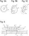
- Figure 5 shows a top view of the component and, more specifically, shows how further zone 8, opening 7 and zone 5 relate to each other. Because figure 5 shows a top view, the upright edge 9 is shown with a full line, the edge of opening 7 is shown with a full line and, with a view to the description, the edge 6 is shown with a broken line. Edge 6 is situated on the underside of component 1 and is not visible in a top view in normal circumstances.
- Figure 5A shows the top view of component 1 of figure 1 . In this component opening 7 is positioned substantially centrally within an upright edge 9 which extends all around opening 7. The edge 6 which delimits zone 5 is placed at a slightly greater distance from the edge of opening 7 than upright edge 9. Zone 5, delimited by edge 6, hereby extends slightly further than further zone 8, delimited by upright edge 9.
- a good clamping of component 1 within the at least partially cured compound is obtained when the surface area of the zone, delimited by edge 6, is greater than the surface area of opening 7, and more preferably at least double the size of surface area of opening 7.
- the sum of openings will in this context be deemed the surface area of opening 7.
- the surface area of the further zone 8 delimited by upright edge 9 is also greater than the surface area of opening 7, and preferably double the size of surface area of opening 7.
- Zones 5 and 8 hereby extend sufficiently over the edges 13 of opening 7 to hold these edges mechanically.
- the opening 7 preferably covers a surface area which is sufficiently great to avoid tearing off of the compound in the opening in the context of use of component 1.
- the skilled person will also appreciate that the thickness of the compound at the position of zone 5 and zone 8 must be sufficient to prevent tearing off of the compound in a normal context of use of component 1.
- Figures 5B and 5C show alternative embodiments of the invention in which a plurality of openings 7 is provided.
- Figure 5B clearly shows that the shape of zone 5 can differ from the shape of further zone 8.
- Figure 5C shows an embodiment wherein two openings 7 are provided, wherein two zones 5 are delimited by edges 6, each situated under each of the respective openings. At the position of the upper side of the component one upright edge 9 is provided for the two openings 7.
- Upright edge 9 is here formed such that not the whole edge of openings 7 is covered by further zone 8. Because the further zone does however extend over a portion of the edges of openings 7, a mechanical locking of the component relative to the compound is still obtained.
- a mechanical connection is defined as a connection between two elements which is created as a direct result of a compatibility of shape between these two elements.
- the shape and position of the two elements relative to each other prevent the relative movement of the elements relative to each other, irrespective of any adhesive force between the elements.
- An adhesive connection is defined as a connection between two elements which is created as a direct result of an adhesive force between these two elements.
- An adhesive connection can connect two elements to each other irrespective of the shape.
- Figure 6 shows an alternative embodiment wherein the surface area of the lower zone is substantially the same size as the surface area of opening 7.
- a sufficiently large surface area of opening 7 is chosen.
- a plurality of openings is for this purpose provided in the embodiment of figure 6 . Because of the specific construction, it is no longer possible to distinguish physically between opening 7 and lower zone 5.
- a lower segment of opening 7 is in this embodiment deemed a lower zone 5.
- the mechanical connection between cured compound 3 and component 1 is still realized in that an upper zone 8 is at least partially filled with compound 3. The skilled person will appreciate that the component is clamped between upper zone 8 and panel 2.
- Figure 7 shows a further application of the above described component. More specifically, figure 7 shows an external part 14 which is connected to the panel via at least one, preferably at least two components as described above. External part 14 has for this purpose an edge 15. In the embodiment of figure 7a the edge 15 takes a substantially continuous form and a plurality of components 1 can be placed at different locations along the edge 15 and grip with their flange 16 over the edge. External part 14 is hereby connected via the components to the panel.
- each component has a flange 16 which engages over the edge 15 of part 14. More specifically, component 1 extends with its flange 16 at least partially over edge 15 of part 14 such that part 14 is situated with its edge 15 between panel 2 and flange 16.
- part 14 is hereby indirectly connected to panel 2. This technique allows an external part 14 to be connected to a panel 2 without the provision of glue or a another bond directly between part 14 and panel 2.
- Each component is provided with an edge 6, an opening 7 and an upright edge 9, as described at length above.
- Each component can hereby be fixedly connected to the panel, wherein a bond between the compound and the panel on the one hand and a mechanical connection between the compound and the component on the other hand provides for the connection.
- the external part is also fixedly connected to panel 2 by a mechanical clamping between components 1a, 1b and 1c on the one hand and part 14 on the other.
- Figure 7b shows an alternative embodiment wherein an external part 14 does not have continuous edge 15.
- External part 14 has two opposite edges 15a and 15b which extend over only a limited portion of the periphery of external part 14.
- components 1a and 1b are fixedly connected to panel 2.
- Components 1a and 1b extend with their flange 16 over the respective edges 15a and 15b in order to connect the external components 14 via components 1a and 1b to the panel.
- Figures 7a and 7b illustrate that the appearance of components 1 is not important and can be chosen on the basis of available space and operating parameters in order to realize a good connection within the available space.
- Figure 8 shows an embodiment of a component 1 with a flange 16 which is suitable for holding an external part 14 on a panel 2.
- Figure 8 shows external part 14 with a broken line.
- External part 14 has an edge 15. At least a portion of component 1 extends over the edge, more specifically, flange 16 of component 1 extends over edge 15. In this way flange 16 holds edge 15 on panel 2.
- Component 1 is connected to the panel, as described at length above. Component 1 is for this purpose provided with an edge 6. In the embodiment of figure 8 edge 6 is at the same time the spacer. Edge 6 forms a zone 5 in which the compound can spread. Further provided is an opening and an upright edge 9 which forms the further zone 8. In the embodiment of figure 8 a portion of upright edge 9 is formed by flange 16. Flange 16 extends at a distance from panel 2 when component 1 is connected to panel 2. In the embodiment of figure 8 the distance between flange 16 and panel 2 is not constant, but the distance is smaller proximally of the flange and greater distally thereof. In other words, a tapered space is formed between flange 16 and the panel.
- component 1 is usable in many situations and for the purpose of fixing various external components, wherein the shape and thickness of the edges 15 of external components 14 can vary. Owing to the tapered space, the position of the component relative to the external part can be chosen so as to obtain a predetermined clamping.
Landscapes
- Engineering & Computer Science (AREA)
- General Engineering & Computer Science (AREA)
- Mechanical Engineering (AREA)
- Body Structure For Vehicles (AREA)
Claims (13)
- Procédé pour relier une pièce externe (14) à un panneau (2) en utilisant au moins deux éléments (la, 1b, lc), dans lequel chaque élément a un collet (16) pour venir en prise au moins partiellement sur un bord (15) de la pièce externe, et dans lequel le procédé comprend le placement des deux éléments venant chacun en prise avec leur collet sur le bord et relient ainsi la pièce externe au panneau via les deux éléments dans lequel chaque élément comprend un côté de liaison (4) qui est positionné à une distance du panneau et dans lequel un composé (11) est introduit entre le côté de liaison et le panneau, une zone (5) est délimitée entre le côté de liaison et le panneau de sorte qu'une barrière physique (6) soit formée pour le composé, laquelle zone a au moins une ouverture (7) dans le côté de liaison, et dans lequel un composé sous forme liquide est appliqué au-dessus de l'ouverture de manière à couler à travers l'ouverture et remplir la zone, dans lequel au-dessus de ladite ouverture une autre zone (8) est au moins partiellement remplie par le composé de sorte que, après un durcissement au moins partiel du composé, l'élément soit maintenu mécaniquement par le composé.
- Procédé selon la revendication 1, dans lequel le composé a une viscosité dynamique, mesurée à un taux de cisaillement de 1/s, de moins de 35 000 mPa.s lorsqu'il vient à reposer sur au moins une partie du panneau.
- Procédé selon la revendication 1 ou 2, dans lequel le panneau est un panneau de verre.
- Procédé selon l'une quelconque des revendications précitées, dans lequel la zone est délimitée par la fourniture d'un bord qui s'étend tout autour de la zone entre le côté de liaison et le panneau afin d'empêcher la colle de couler au-delà du bord.
- Procédé selon la revendication 4, dans lequel le bord est formé par une portion épaissie sur le côté de liaison de l'élément.
- Procédé selon la revendication 4 ou 5, dans lequel le bord est formé par un matériau compressible et a une épaisseur égale à ou plus grande que la distance spécifiée, de sorte que des tolérances dans ladite distance soient compensées par le bord.
- Procédé selon l'une quelconque des revendications précitées, dans lequel le procédé se compose en outre, durant ou après le positionnement de l'élément, de l'orientation du panneau avec l'élément de sorte que l'ouverture soit située au-dessus de la zone.
- Procédé selon l'une quelconque des revendications précitées, dans lequel l'autre zone est délimitée par la fourniture d'un bord droit (9) qui s'étend tout autour de l'ouverture.
- Procédé selon l'une quelconque des revendications précitées, dans lequel l'ouverture couvre une première superficie et dans lequel la zone s'étend sur une deuxième superficie, plus grande que la première superficie, et dans lequel l'autre zone s'étend sur une troisième superficie plus grande que la première superficie.
- Procédé selon la revendication 9, dans lequel la deuxième superficie est au moins le double de la taille de la première superficie et dans lequel la troisième superficie est au moins le double de la taille de la première superficie.
- Procédé selon la revendication 9 ou 10, dans lequel la taille de la première superficie s'élève à au moins 5 %, de préférence au moins 10 %, de la taille de la deuxième superficie.
- Procédé selon l'une quelconque des revendications précitées, dans lequel la zone est formée avec une épaisseur plus grande que 0,5 mm, de préférence plus grande que 1,0 mm.
- Procédé selon l'une quelconque des revendications précitées, dans lequel l'autre zone est remplie de sorte que le composé s'étende sur au moins 0,5 mm, de préférence au moins 1,0 mm, au-dessus du bord de l'ouverture.
Applications Claiming Priority (2)
| Application Number | Priority Date | Filing Date | Title |
|---|---|---|---|
| BE2018/5142A BE1026082B1 (nl) | 2018-03-08 | 2018-03-08 | Verbinden van component met glas |
| PCT/IB2019/051612 WO2019171221A1 (fr) | 2018-03-08 | 2019-02-28 | Liaison d'un élément à du verre |
Publications (2)
| Publication Number | Publication Date |
|---|---|
| EP3762620A1 EP3762620A1 (fr) | 2021-01-13 |
| EP3762620B1 true EP3762620B1 (fr) | 2022-09-28 |
Family
ID=61800224
Family Applications (1)
| Application Number | Title | Priority Date | Filing Date |
|---|---|---|---|
| EP19712627.9A Active EP3762620B1 (fr) | 2018-03-08 | 2019-02-28 | Liaison d'un élément à du verre |
Country Status (4)
| Country | Link |
|---|---|
| EP (1) | EP3762620B1 (fr) |
| BE (1) | BE1026082B1 (fr) |
| PL (1) | PL3762620T3 (fr) |
| WO (1) | WO2019171221A1 (fr) |
Families Citing this family (1)
| Publication number | Priority date | Publication date | Assignee | Title |
|---|---|---|---|---|
| BE1028024B1 (nl) * | 2020-01-31 | 2021-08-30 | Exypnos Bvba | Verlijmen van elementen |
Citations (16)
| Publication number | Priority date | Publication date | Assignee | Title |
|---|---|---|---|---|
| US4250596A (en) | 1979-11-19 | 1981-02-17 | Nifco, Inc. | Fastening system for securing a trim-fixing device to a substrate |
| EP0379246A2 (fr) | 1989-01-20 | 1990-07-25 | Recticel | Procédé de préparation et d'utilisation d'un polyuréthane pulvérisable stable à la lumière |
| DE4444546A1 (de) | 1993-12-23 | 1995-07-13 | Volkswagen Ag | Klebeverbindung und -verfahren für Polyethylen- und Polypropylenschäume |
| EP0870933A2 (fr) | 1997-04-07 | 1998-10-14 | HENNIGES ELASTOMER- UND KUNSTSTOFFTECHNIK GMBH & CO KG | Dispositif et procédé pour réaliser une connection entre deux éléments |
| EP0931641A2 (fr) | 1998-01-22 | 1999-07-28 | HENNIGES ELASTOMER- UND KUNSTSTOFFTECHNIK GMBH & CO KG | Procédé pour joindre une pièce de construction avec un élément de construction |
| WO2001081774A1 (fr) | 2000-04-25 | 2001-11-01 | Ernst Georg Ortwein | Procede et systeme de montage pour l"installation d"un element de fixation sur un mur |
| US6581484B1 (en) | 1997-08-19 | 2003-06-24 | Valeo Auto-Electric Wischer Und Motoren Gmbh | Sensor joined to a glass pane with a silicon gel |
| EP1329580A2 (fr) | 2002-01-02 | 2003-07-23 | Denis Dontenville | Elément de charnière pour panneaux vitrés |
| DE10211444A1 (de) | 2002-03-15 | 2003-10-09 | Daimler Chrysler Ag | Halterung zum Befestigen eines Bauteils an einer Glasscheibe |
| FR2952143A1 (fr) | 2009-11-05 | 2011-05-06 | Peugeot Citroen Automobiles Sa | Dispositif de jonction entre deux elements vitres, notamment pour vehicule automobile |
| WO2012042172A1 (fr) | 2010-09-28 | 2012-04-05 | Saint-Gobain Glass France | Vitrage a joint profile encapsule et piece rapportee fixee au joint, element de fixation de la piece rapportee pour le vitrage et procede de fabrication du vitrage. |
| US20120121855A1 (en) | 2010-11-16 | 2012-05-17 | Hon Hai Precision Industry Co., Ltd. | Adhesive assembly and method for making same |
| WO2014049256A1 (fr) | 2012-09-25 | 2014-04-03 | Saint-Gobain Glass France | Vitrage a joint profile encapsule et piece rapportee fixee au joint, element de fixation de la piece rapportee pour le vitrage et procede de fabrication du vitrage |
| CN204136894U (zh) | 2014-07-31 | 2015-02-04 | 象山华鹰塑料工程有限公司 | 一种将摄像头安装在后视镜支架面板的连接结构 |
| FR3029990A1 (fr) | 2014-12-10 | 2016-06-17 | Seat Sa | Piece de fixation et procede pour fixer ladite piece de fixation avec une seconde piece |
| CN206678918U (zh) | 2017-04-24 | 2017-11-28 | 北京奔驰汽车有限公司 | 一种汽车前风挡贴膜 |
-
2018
- 2018-03-08 BE BE2018/5142A patent/BE1026082B1/nl not_active IP Right Cessation
-
2019
- 2019-02-28 EP EP19712627.9A patent/EP3762620B1/fr active Active
- 2019-02-28 WO PCT/IB2019/051612 patent/WO2019171221A1/fr not_active Ceased
- 2019-02-28 PL PL19712627.9T patent/PL3762620T3/pl unknown
Patent Citations (16)
| Publication number | Priority date | Publication date | Assignee | Title |
|---|---|---|---|---|
| US4250596A (en) | 1979-11-19 | 1981-02-17 | Nifco, Inc. | Fastening system for securing a trim-fixing device to a substrate |
| EP0379246A2 (fr) | 1989-01-20 | 1990-07-25 | Recticel | Procédé de préparation et d'utilisation d'un polyuréthane pulvérisable stable à la lumière |
| DE4444546A1 (de) | 1993-12-23 | 1995-07-13 | Volkswagen Ag | Klebeverbindung und -verfahren für Polyethylen- und Polypropylenschäume |
| EP0870933A2 (fr) | 1997-04-07 | 1998-10-14 | HENNIGES ELASTOMER- UND KUNSTSTOFFTECHNIK GMBH & CO KG | Dispositif et procédé pour réaliser une connection entre deux éléments |
| US6581484B1 (en) | 1997-08-19 | 2003-06-24 | Valeo Auto-Electric Wischer Und Motoren Gmbh | Sensor joined to a glass pane with a silicon gel |
| EP0931641A2 (fr) | 1998-01-22 | 1999-07-28 | HENNIGES ELASTOMER- UND KUNSTSTOFFTECHNIK GMBH & CO KG | Procédé pour joindre une pièce de construction avec un élément de construction |
| WO2001081774A1 (fr) | 2000-04-25 | 2001-11-01 | Ernst Georg Ortwein | Procede et systeme de montage pour l"installation d"un element de fixation sur un mur |
| EP1329580A2 (fr) | 2002-01-02 | 2003-07-23 | Denis Dontenville | Elément de charnière pour panneaux vitrés |
| DE10211444A1 (de) | 2002-03-15 | 2003-10-09 | Daimler Chrysler Ag | Halterung zum Befestigen eines Bauteils an einer Glasscheibe |
| FR2952143A1 (fr) | 2009-11-05 | 2011-05-06 | Peugeot Citroen Automobiles Sa | Dispositif de jonction entre deux elements vitres, notamment pour vehicule automobile |
| WO2012042172A1 (fr) | 2010-09-28 | 2012-04-05 | Saint-Gobain Glass France | Vitrage a joint profile encapsule et piece rapportee fixee au joint, element de fixation de la piece rapportee pour le vitrage et procede de fabrication du vitrage. |
| US20120121855A1 (en) | 2010-11-16 | 2012-05-17 | Hon Hai Precision Industry Co., Ltd. | Adhesive assembly and method for making same |
| WO2014049256A1 (fr) | 2012-09-25 | 2014-04-03 | Saint-Gobain Glass France | Vitrage a joint profile encapsule et piece rapportee fixee au joint, element de fixation de la piece rapportee pour le vitrage et procede de fabrication du vitrage |
| CN204136894U (zh) | 2014-07-31 | 2015-02-04 | 象山华鹰塑料工程有限公司 | 一种将摄像头安装在后视镜支架面板的连接结构 |
| FR3029990A1 (fr) | 2014-12-10 | 2016-06-17 | Seat Sa | Piece de fixation et procede pour fixer ladite piece de fixation avec une seconde piece |
| CN206678918U (zh) | 2017-04-24 | 2017-11-28 | 北京奔驰汽车有限公司 | 一种汽车前风挡贴膜 |
Non-Patent Citations (2)
| Title |
|---|
| BANEA M D, ET AL: "The Effect of Adhesive Thickness on the Mechanical Behavior of a Structural Polyurethane Adhesive", THE JOURNAL OF ADHESION, vol. 91, 1 January 2015 (2015-01-01), pages 331 - 346, XP093066010 |
| YOUTUBE, 18 January 2018 (2018-01-18) |
Also Published As
| Publication number | Publication date |
|---|---|
| EP3762620A1 (fr) | 2021-01-13 |
| BE1026082A1 (nl) | 2019-10-03 |
| BE1026082B1 (nl) | 2019-10-10 |
| WO2019171221A1 (fr) | 2019-09-12 |
| PL3762620T3 (pl) | 2022-12-19 |
Similar Documents
| Publication | Publication Date | Title |
|---|---|---|
| JP3107389B2 (ja) | 窓ガラス及び窓ガラスの取付け方法 | |
| US9308804B2 (en) | Method of attaching functional components to a roof element of a vehicle, and vehicle roof element | |
| JP4179633B2 (ja) | 封入窓及びその製造法 | |
| US7640808B2 (en) | Strip with acoustic damping properties | |
| JPH02122920A (ja) | 一体成形複合部品及びその製造法 | |
| GB2415162A (en) | Improvements in or relating to laminar mouldings | |
| CZ8894A3 (en) | Car glass being pre-treated for sticking in an opening and process for producing thereof | |
| CA2472727A1 (fr) | Corps structurel renforce et procede de fabrication de celui-ci | |
| JPH0858362A (ja) | 溶融処理可能なガスケット材料を使用したグレージング | |
| JP2011508700A (ja) | 窓ガラス構造 | |
| EP3762620B1 (fr) | Liaison d'un élément à du verre | |
| RU2744088C2 (ru) | Сдвигаемое многослойное остекление с внутренним выступом | |
| CZ20023757A3 (cs) | Způsob výroby modulového prvku připraveného k připevnění a způsob jeho montáže | |
| EP2501574A1 (fr) | Élément de ferrure et procédé pour sa fabrication et son collage | |
| KR20090122427A (ko) | 유리를 접착에 의해 그것의 홀더 상에 조립하는 방법, 및 상기 방법을 구현하는 수단 | |
| JP4777649B2 (ja) | 車両用可動窓ガラス及び車両用ドロップ・ガラスの製造方法 | |
| JPH11314525A (ja) | シール部を有する開閉体の製造方法及び車両用サンルーフ | |
| JP2019043819A (ja) | 複合体およびその製造方法 | |
| EP1353816A1 (fr) | Procede d'installation d'une fenetre fixe et fenetre fixe | |
| EP3056367B1 (fr) | Guidage de verre de véhicule et élément d'étanchéité | |
| EP3858494A1 (fr) | Agglutiner des éléments | |
| CN113195201B (zh) | 包括胶合在结构部件上的外观部件的车辆车身元件 | |
| KR100512274B1 (ko) | 점성이 없는 보강제로 차체 구조물을 보강하는 방법 | |
| JP2023537306A (ja) | ウィンドウホルダを含む車両ウィンドウ | |
| CN107585002A (zh) | 玻璃盖单元和用于制造所述玻璃盖单元的方法 |
Legal Events
| Date | Code | Title | Description |
|---|---|---|---|
| STAA | Information on the status of an ep patent application or granted ep patent |
Free format text: STATUS: UNKNOWN |
|
| STAA | Information on the status of an ep patent application or granted ep patent |
Free format text: STATUS: THE INTERNATIONAL PUBLICATION HAS BEEN MADE |
|
| PUAI | Public reference made under article 153(3) epc to a published international application that has entered the european phase |
Free format text: ORIGINAL CODE: 0009012 |
|
| STAA | Information on the status of an ep patent application or granted ep patent |
Free format text: STATUS: REQUEST FOR EXAMINATION WAS MADE |
|
| 17P | Request for examination filed |
Effective date: 20201005 |
|
| AK | Designated contracting states |
Kind code of ref document: A1 Designated state(s): AL AT BE BG CH CY CZ DE DK EE ES FI FR GB GR HR HU IE IS IT LI LT LU LV MC MK MT NL NO PL PT RO RS SE SI SK SM TR |
|
| AX | Request for extension of the european patent |
Extension state: BA ME |
|
| DAV | Request for validation of the european patent (deleted) | ||
| DAX | Request for extension of the european patent (deleted) | ||
| GRAP | Despatch of communication of intention to grant a patent |
Free format text: ORIGINAL CODE: EPIDOSNIGR1 |
|
| STAA | Information on the status of an ep patent application or granted ep patent |
Free format text: STATUS: GRANT OF PATENT IS INTENDED |
|
| INTG | Intention to grant announced |
Effective date: 20220419 |
|
| GRAS | Grant fee paid |
Free format text: ORIGINAL CODE: EPIDOSNIGR3 |
|
| GRAA | (expected) grant |
Free format text: ORIGINAL CODE: 0009210 |
|
| STAA | Information on the status of an ep patent application or granted ep patent |
Free format text: STATUS: THE PATENT HAS BEEN GRANTED |
|
| AK | Designated contracting states |
Kind code of ref document: B1 Designated state(s): AL AT BE BG CH CY CZ DE DK EE ES FI FR GB GR HR HU IE IS IT LI LT LU LV MC MK MT NL NO PL PT RO RS SE SI SK SM TR |
|
| REG | Reference to a national code |
Ref country code: GB Ref legal event code: FG4D |
|
| REG | Reference to a national code |
Ref country code: CH Ref legal event code: EP |
|
| REG | Reference to a national code |
Ref country code: AT Ref legal event code: REF Ref document number: 1521400 Country of ref document: AT Kind code of ref document: T Effective date: 20221015 |
|
| REG | Reference to a national code |
Ref country code: DE Ref legal event code: R096 Ref document number: 602019020033 Country of ref document: DE |
|
| REG | Reference to a national code |
Ref country code: IE Ref legal event code: FG4D |
|
| REG | Reference to a national code |
Ref country code: NL Ref legal event code: FP |
|
| REG | Reference to a national code |
Ref country code: LT Ref legal event code: MG9D |
|
| PG25 | Lapsed in a contracting state [announced via postgrant information from national office to epo] |
Ref country code: SE Free format text: LAPSE BECAUSE OF FAILURE TO SUBMIT A TRANSLATION OF THE DESCRIPTION OR TO PAY THE FEE WITHIN THE PRESCRIBED TIME-LIMIT Effective date: 20220928 Ref country code: RS Free format text: LAPSE BECAUSE OF FAILURE TO SUBMIT A TRANSLATION OF THE DESCRIPTION OR TO PAY THE FEE WITHIN THE PRESCRIBED TIME-LIMIT Effective date: 20220928 Ref country code: NO Free format text: LAPSE BECAUSE OF FAILURE TO SUBMIT A TRANSLATION OF THE DESCRIPTION OR TO PAY THE FEE WITHIN THE PRESCRIBED TIME-LIMIT Effective date: 20221228 Ref country code: LV Free format text: LAPSE BECAUSE OF FAILURE TO SUBMIT A TRANSLATION OF THE DESCRIPTION OR TO PAY THE FEE WITHIN THE PRESCRIBED TIME-LIMIT Effective date: 20220928 Ref country code: LT Free format text: LAPSE BECAUSE OF FAILURE TO SUBMIT A TRANSLATION OF THE DESCRIPTION OR TO PAY THE FEE WITHIN THE PRESCRIBED TIME-LIMIT Effective date: 20220928 Ref country code: FI Free format text: LAPSE BECAUSE OF FAILURE TO SUBMIT A TRANSLATION OF THE DESCRIPTION OR TO PAY THE FEE WITHIN THE PRESCRIBED TIME-LIMIT Effective date: 20220928 |
|
| REG | Reference to a national code |
Ref country code: AT Ref legal event code: MK05 Ref document number: 1521400 Country of ref document: AT Kind code of ref document: T Effective date: 20220928 |
|
| PG25 | Lapsed in a contracting state [announced via postgrant information from national office to epo] |
Ref country code: HR Free format text: LAPSE BECAUSE OF FAILURE TO SUBMIT A TRANSLATION OF THE DESCRIPTION OR TO PAY THE FEE WITHIN THE PRESCRIBED TIME-LIMIT Effective date: 20220928 Ref country code: GR Free format text: LAPSE BECAUSE OF FAILURE TO SUBMIT A TRANSLATION OF THE DESCRIPTION OR TO PAY THE FEE WITHIN THE PRESCRIBED TIME-LIMIT Effective date: 20221229 |
|
| PG25 | Lapsed in a contracting state [announced via postgrant information from national office to epo] |
Ref country code: SM Free format text: LAPSE BECAUSE OF FAILURE TO SUBMIT A TRANSLATION OF THE DESCRIPTION OR TO PAY THE FEE WITHIN THE PRESCRIBED TIME-LIMIT Effective date: 20220928 Ref country code: RO Free format text: LAPSE BECAUSE OF FAILURE TO SUBMIT A TRANSLATION OF THE DESCRIPTION OR TO PAY THE FEE WITHIN THE PRESCRIBED TIME-LIMIT Effective date: 20220928 Ref country code: PT Free format text: LAPSE BECAUSE OF FAILURE TO SUBMIT A TRANSLATION OF THE DESCRIPTION OR TO PAY THE FEE WITHIN THE PRESCRIBED TIME-LIMIT Effective date: 20230130 Ref country code: ES Free format text: LAPSE BECAUSE OF FAILURE TO SUBMIT A TRANSLATION OF THE DESCRIPTION OR TO PAY THE FEE WITHIN THE PRESCRIBED TIME-LIMIT Effective date: 20220928 Ref country code: CZ Free format text: LAPSE BECAUSE OF FAILURE TO SUBMIT A TRANSLATION OF THE DESCRIPTION OR TO PAY THE FEE WITHIN THE PRESCRIBED TIME-LIMIT Effective date: 20220928 Ref country code: AT Free format text: LAPSE BECAUSE OF FAILURE TO SUBMIT A TRANSLATION OF THE DESCRIPTION OR TO PAY THE FEE WITHIN THE PRESCRIBED TIME-LIMIT Effective date: 20220928 |
|
| PG25 | Lapsed in a contracting state [announced via postgrant information from national office to epo] |
Ref country code: SK Free format text: LAPSE BECAUSE OF FAILURE TO SUBMIT A TRANSLATION OF THE DESCRIPTION OR TO PAY THE FEE WITHIN THE PRESCRIBED TIME-LIMIT Effective date: 20220928 Ref country code: IS Free format text: LAPSE BECAUSE OF FAILURE TO SUBMIT A TRANSLATION OF THE DESCRIPTION OR TO PAY THE FEE WITHIN THE PRESCRIBED TIME-LIMIT Effective date: 20230128 Ref country code: EE Free format text: LAPSE BECAUSE OF FAILURE TO SUBMIT A TRANSLATION OF THE DESCRIPTION OR TO PAY THE FEE WITHIN THE PRESCRIBED TIME-LIMIT Effective date: 20220928 |
|
| REG | Reference to a national code |
Ref country code: DE Ref legal event code: R026 Ref document number: 602019020033 Country of ref document: DE |
|
| PG25 | Lapsed in a contracting state [announced via postgrant information from national office to epo] |
Ref country code: AL Free format text: LAPSE BECAUSE OF FAILURE TO SUBMIT A TRANSLATION OF THE DESCRIPTION OR TO PAY THE FEE WITHIN THE PRESCRIBED TIME-LIMIT Effective date: 20220928 |
|
| PLBI | Opposition filed |
Free format text: ORIGINAL CODE: 0009260 |
|
| PG25 | Lapsed in a contracting state [announced via postgrant information from national office to epo] |
Ref country code: DK Free format text: LAPSE BECAUSE OF FAILURE TO SUBMIT A TRANSLATION OF THE DESCRIPTION OR TO PAY THE FEE WITHIN THE PRESCRIBED TIME-LIMIT Effective date: 20220928 |
|
| 26 | Opposition filed |
Opponent name: AGC GLASS EUROPE Effective date: 20230621 |
|
| REG | Reference to a national code |
Ref country code: DE Ref legal event code: R119 Ref document number: 602019020033 Country of ref document: DE |
|
| PLAX | Notice of opposition and request to file observation + time limit sent |
Free format text: ORIGINAL CODE: EPIDOSNOBS2 |
|
| PG25 | Lapsed in a contracting state [announced via postgrant information from national office to epo] |
Ref country code: MC Free format text: LAPSE BECAUSE OF FAILURE TO SUBMIT A TRANSLATION OF THE DESCRIPTION OR TO PAY THE FEE WITHIN THE PRESCRIBED TIME-LIMIT Effective date: 20220928 |
|
| REG | Reference to a national code |
Ref country code: CH Ref legal event code: PL |
|
| REG | Reference to a national code |
Ref country code: NL Ref legal event code: MM Effective date: 20230301 |
|
| REG | Reference to a national code |
Ref country code: BE Ref legal event code: MM Effective date: 20230228 |
|
| GBPC | Gb: european patent ceased through non-payment of renewal fee |
Effective date: 20230228 |
|
| PG25 | Lapsed in a contracting state [announced via postgrant information from national office to epo] |
Ref country code: LU Free format text: LAPSE BECAUSE OF NON-PAYMENT OF DUE FEES Effective date: 20230228 Ref country code: LI Free format text: LAPSE BECAUSE OF NON-PAYMENT OF DUE FEES Effective date: 20230228 Ref country code: CH Free format text: LAPSE BECAUSE OF NON-PAYMENT OF DUE FEES Effective date: 20230228 |
|
| PG25 | Lapsed in a contracting state [announced via postgrant information from national office to epo] |
Ref country code: SI Free format text: LAPSE BECAUSE OF FAILURE TO SUBMIT A TRANSLATION OF THE DESCRIPTION OR TO PAY THE FEE WITHIN THE PRESCRIBED TIME-LIMIT Effective date: 20220928 Ref country code: NL Free format text: LAPSE BECAUSE OF NON-PAYMENT OF DUE FEES Effective date: 20230301 |
|
| REG | Reference to a national code |
Ref country code: IE Ref legal event code: MM4A |
|
| PG25 | Lapsed in a contracting state [announced via postgrant information from national office to epo] |
Ref country code: GB Free format text: LAPSE BECAUSE OF NON-PAYMENT OF DUE FEES Effective date: 20230228 |
|
| PG25 | Lapsed in a contracting state [announced via postgrant information from national office to epo] |
Ref country code: IE Free format text: LAPSE BECAUSE OF NON-PAYMENT OF DUE FEES Effective date: 20230228 Ref country code: GB Free format text: LAPSE BECAUSE OF NON-PAYMENT OF DUE FEES Effective date: 20230228 Ref country code: FR Free format text: LAPSE BECAUSE OF NON-PAYMENT OF DUE FEES Effective date: 20230228 Ref country code: DE Free format text: LAPSE BECAUSE OF NON-PAYMENT OF DUE FEES Effective date: 20230901 |
|
| PG25 | Lapsed in a contracting state [announced via postgrant information from national office to epo] |
Ref country code: BE Free format text: LAPSE BECAUSE OF NON-PAYMENT OF DUE FEES Effective date: 20230228 |
|
| PG25 | Lapsed in a contracting state [announced via postgrant information from national office to epo] |
Ref country code: IT Free format text: LAPSE BECAUSE OF FAILURE TO SUBMIT A TRANSLATION OF THE DESCRIPTION OR TO PAY THE FEE WITHIN THE PRESCRIBED TIME-LIMIT Effective date: 20220928 |
|
| PG25 | Lapsed in a contracting state [announced via postgrant information from national office to epo] |
Ref country code: BG Free format text: LAPSE BECAUSE OF FAILURE TO SUBMIT A TRANSLATION OF THE DESCRIPTION OR TO PAY THE FEE WITHIN THE PRESCRIBED TIME-LIMIT Effective date: 20220928 |
|
| PG25 | Lapsed in a contracting state [announced via postgrant information from national office to epo] |
Ref country code: BG Free format text: LAPSE BECAUSE OF FAILURE TO SUBMIT A TRANSLATION OF THE DESCRIPTION OR TO PAY THE FEE WITHIN THE PRESCRIBED TIME-LIMIT Effective date: 20220928 |
|
| PG25 | Lapsed in a contracting state [announced via postgrant information from national office to epo] |
Ref country code: PL Free format text: LAPSE BECAUSE OF NON-PAYMENT OF DUE FEES Effective date: 20230228 |
|
| PG25 | Lapsed in a contracting state [announced via postgrant information from national office to epo] |
Ref country code: PL Free format text: LAPSE BECAUSE OF NON-PAYMENT OF DUE FEES Effective date: 20230228 |
|
| PLCK | Communication despatched that opposition was rejected |
Free format text: ORIGINAL CODE: EPIDOSNREJ1 |
|
| REG | Reference to a national code |
Ref country code: DE Ref legal event code: R100 Ref document number: 602019020033 Country of ref document: DE |
|
| PLBN | Opposition rejected |
Free format text: ORIGINAL CODE: 0009273 |
|
| STAA | Information on the status of an ep patent application or granted ep patent |
Free format text: STATUS: OPPOSITION REJECTED |
|
| 27O | Opposition rejected |
Effective date: 20250225 |
|
| PG25 | Lapsed in a contracting state [announced via postgrant information from national office to epo] |
Ref country code: CY Free format text: LAPSE BECAUSE OF FAILURE TO SUBMIT A TRANSLATION OF THE DESCRIPTION OR TO PAY THE FEE WITHIN THE PRESCRIBED TIME-LIMIT; INVALID AB INITIO Effective date: 20190228 |
|
| PG25 | Lapsed in a contracting state [announced via postgrant information from national office to epo] |
Ref country code: HU Free format text: LAPSE BECAUSE OF FAILURE TO SUBMIT A TRANSLATION OF THE DESCRIPTION OR TO PAY THE FEE WITHIN THE PRESCRIBED TIME-LIMIT; INVALID AB INITIO Effective date: 20190228 |
|
| PG25 | Lapsed in a contracting state [announced via postgrant information from national office to epo] |
Ref country code: TR Free format text: LAPSE BECAUSE OF FAILURE TO SUBMIT A TRANSLATION OF THE DESCRIPTION OR TO PAY THE FEE WITHIN THE PRESCRIBED TIME-LIMIT Effective date: 20220928 |