EP3762671B1 - Wärmetauscher - Google Patents
Wärmetauscher Download PDFInfo
- Publication number
- EP3762671B1 EP3762671B1 EP19709556.5A EP19709556A EP3762671B1 EP 3762671 B1 EP3762671 B1 EP 3762671B1 EP 19709556 A EP19709556 A EP 19709556A EP 3762671 B1 EP3762671 B1 EP 3762671B1
- Authority
- EP
- European Patent Office
- Prior art keywords
- channel
- heat exchanger
- fluid
- conduit
- channels
- Prior art date
- Legal status (The legal status is an assumption and is not a legal conclusion. Google has not performed a legal analysis and makes no representation as to the accuracy of the status listed.)
- Active
Links
Images



Classifications
-
- F—MECHANICAL ENGINEERING; LIGHTING; HEATING; WEAPONS; BLASTING
- F28—HEAT EXCHANGE IN GENERAL
- F28F—DETAILS OF HEAT-EXCHANGE AND HEAT-TRANSFER APPARATUS, OF GENERAL APPLICATION
- F28F7/00—Elements not covered by group F28F1/00, F28F3/00 or F28F5/00
- F28F7/02—Blocks traversed by passages for heat-exchange media
-
- B—PERFORMING OPERATIONS; TRANSPORTING
- B33—ADDITIVE MANUFACTURING TECHNOLOGY
- B33Y—ADDITIVE MANUFACTURING, i.e. MANUFACTURING OF THREE-DIMENSIONAL [3D] OBJECTS BY ADDITIVE DEPOSITION, ADDITIVE AGGLOMERATION OR ADDITIVE LAYERING, e.g. BY 3D PRINTING, STEREOLITHOGRAPHY OR SELECTIVE LASER SINTERING
- B33Y80/00—Products made by additive manufacturing
-
- F—MECHANICAL ENGINEERING; LIGHTING; HEATING; WEAPONS; BLASTING
- F28—HEAT EXCHANGE IN GENERAL
- F28F—DETAILS OF HEAT-EXCHANGE AND HEAT-TRANSFER APPARATUS, OF GENERAL APPLICATION
- F28F2250/00—Arrangements for modifying the flow of the heat exchange media, e.g. flow guiding means; Particular flow patterns
- F28F2250/04—Communication passages between channels
Definitions
- a heat exchanger according to the preamble of claim 1 is known from GB 1506721 A .
- Baffles can improve the heat transfer efficiency of a heat exchanger, but can tend to raise the pressure drop across the exchanger.
- first conduits interconnecting the first channel and the third channel, the plurality of first conduits extending through the second channel.
- the first conduit may have an elongate cross sectional form.
- the elongate cross-sectional form may define a shorter aspect S and a longer aspect L wherein the longer aspect is substantially aligned with the predetermined flow direction.
- the longer aspect may be substantially aligned with the incline of the first conduit (for example aligned with the plane defined by the conduit and the channel axes).
- the plurality of first conduits may be spaced apart at regular intervals.
- the plurality of first conduits are arranged in adjacent pairs where one conduit per pair is arranged to promote inter-channel flow from the third channel to the first channel, and the other conduit per pair is arranged to promote inter-channel flow from the first channel to the third channel.
- conduits enables the provision of a repeating unit which can be used to build up a heat exchanger core. It also helps to provide a functionally flexible core where each channel group is suitable for flow in either direction and the core is deployable in either counter flow or co-flow configurations.
- the heat exchanger may further comprise a fourth channel, for communicating between a fourth channel inlet and a fourth channel outlet, a second conduit interconnecting the second channel and the fourth channel and thereby defining a second group of interconnected channels, the second conduit extending through the third channel.
- a heat exchanger may further comprise a plurality of second conduits interconnecting the second channel and the fourth channel, each of the second conduits extending through the third channel.
- such a heat exchanger may provide a plurality of second conduits arranged in adjacent pairs where one conduit per pair is arranged to promote inter-channel flow from the fourth channel to the second, and the other conduit per pair is arranged to promote inter-channel flow from the second channel to the fourth.
- Such a provision can tend to further promote even mixing of fluids between channels, and thereby improve the efficiency of the heat exchanger. Such improved mixing can in turn be associated with an increase in heat transfer.
- first and second conduit pairs are provided, the first conduit pairs and the second conduit pairs occupy an equivalent position in the second and third channel respectively.
- the first conduit is, or the plurality of first conduits are, inclined relative to a central axis defined by the first channel and thereby arranged to promote inter-channel flow.
- the second conduit or the plurality of second conduits can be inclined relative to a central axis defined by the second channel.
- Such conduit inclination can bias certain flows and thereby can tend to mitigate the increases in pressure drop across the exchanger which could otherwise be encountered from the conduits.
- the heat exchanger may comprise a top plate and plurality of base plates mounted between a pair of side walls, wherein the first channel is defined between the top plate, a first base plate and a portion of the side walls, the second channel is defined between the first base plate, the second base plate and a portion of the side walls, the third channel is defined between the second base plate, the third base plate and a portion of the side walls, and The fourth channel is defined between the third base plate, a fourth base plate and a portion of the side walls.
- the first and third channels, being in fluid communication, may be arranged to transport a first fluid in a first flow direction, and the second and fourth channels, being in fluid communication are arranged to transport a second fluid in a second flow direction.
- the first and second flow directions can be generally opposite to provide a counter-flow heat exchanger.
- the heat exchanger may further comprise towards a first end: a first fluid ingress manifold connecting the inlets of the first and third channels to a common first fluid inlet port, a second fluid ingress manifold connecting the outlets of the second and fourth channels to a common second fluid outlet port; and towards a second end: a first fluid egress manifold connecting the outlets of the first and third channels to a common first fluid outlet port, a second fluid egress manifold connecting the inlets of the second and fourth channels to a common second fluid outlet port.
- a method of heat exchange comprising providing a heat exchanger according to the first aspect, causing a coolant fluid to flow through the first and second channel, causing a working fluid to flow through the third channel.
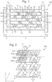
- a first heat exchanger is shown generally at 100 which comprises a first manifold 2, a core 3, and a second manifold 4.
- the heat exchanger 100 is arranged for counter-flow where a first fluid, hot fluid H (which may alternatively be referred to as a working fluid), passes in the opposite direction to a second fluid, cold fluid C (which may alternatively be referred to as a coolant fluid).
- a first fluid hot fluid H (which may alternatively be referred to as a working fluid)
- cold fluid C which may alternatively be referred to as a coolant fluid
- the hot fluid H and the cold fluid C could be arranged for co-flow (where the fluids run in the same direction, e.g. both right-to-left) or cross-flow (where fluids run perpendicular to each other).
- the core 3 comprises a plurality of channels. These channels are configured as two groups, the first group for transporting the first fluid, the second group for transporting the second fluid. Channels alternate by group so that an interleaved arrangement is provided, with channels separated by base plates. A multi-layer stack is thus provided.
- the first group of channels, corresponding with the odd-numbered channels pass fluid in a first direction.
- the second group of channels, corresponding with the even-numbered channels pass the fluid in a second direction.
- a first channel 10 is defined between a top plate 6 and a first base plate 16, and extends between a pair of first channel ports. These ports are configured for a right-to-left (as shown in Figure 1 ) flow direction and as such represent a first inlet 12 communicating with the second manifold 4 and a first outlet 14 communicating with the first manifold 2.
- a second channel 20 is defined between the first base plate 16 and a second base plate 26, and extends between a pair of second channel ports. These ports are configured for a left-to-right (as shown in Figure 1 ) flow direction and as such represent a second inlet 22 communicating with the first manifold 2 and a second outlet 24 communicating with the second manifold 4.
- a third channel 30 is defined between the second base plate 26 and a third base plate 36, and extends between a pair of third channel ports. These ports are configured for a right-to-left (as shown in Figure 1 ) flow direction and as such represent a third inlet 32 communicating with the second manifold 4 and a third outlet 34 communicating with the first manifold 2.
- a fourth channel 40 is defined between the third base plate 36 and the fourth base plate 46, and extends between a pair of fourth channel ports. These ports are configured for to a left-to-right (as shown in Figure 1 ) flow direction and as such represent a fourth inlet 42 communicating with the first manifold 2 and a fourth outlet 44 communicating with the second manifold 4.
- a fifth, sixth and seventh channel (50, 60 and 70 respectively); a fifth and sixth base plate (not numbered so as to reduce visual clutter in the figure), and a bottom plate 7, and their respective inlets and outlets (not numbered).
- the channels are further defined by side walls 5.
- a first group of channels comprises the first, third, fourth, fifth and seventh channels.
- These odd channels can pass a common fluid in a common direction, in this example they pass hot fluid H right to left. In other examples they could pass fluid left to right.
- a second group of channels, the even channels comprises the second, fourth and sixth channels.
- These even channels can pass a common fluid in a common direction, in this example they pass a cold fluid C from left to right. In other examples they could pass fluid right to left.
- channels 10 and 70 provide such outermost layers.
- hot fluid channels pass through these peripheral layers.
- the cold fluid may be passed through a first group of channels providing the peripheral layers of the stack, whilst the hot fluid is passed through a second group of channels interleaved with the first group.
- first group of channels providing the peripheral layers of the stack
- second group of channels interleaved with the first group
- the core 3 comprises a plurality of conduits (spur conduits) which split off their main channel and interconnect with other channels from the same group.
- These interconnecting conduits 8 can be considered to be a spur off of a channel in so far as it offers an alternative flow path to the fluid, but does Is not associated with an occlusion or termination of their main channel).
- a plurality of first conduits 8 provides inter-channel connections between odd-numbered channels. As such a fluid can flow between the interconnected channels.
- Each conduit 8 extends through an even channel but does not fully occlude that even channel.
- conduits 8 are provided, each of which interconnects the first channel 10 and the third channel 30, passing through the second channel 20.
- Some conduits 8 are substantially perpendicular to the channels. Some conduits are inclined to the channels.
- the odd conduits extend only between neighbouring odd channels; however in alternative examples, some odd conduits could extend between other odd channel combinations.
- an odd conduit could connect a first channel 10 and a fifth channel 50, passing through the second 20, third 30, and fourth 40 channels.
- a plurality of second conduits 9 provides inter-channel connections between even-numbered channels. As such a fluid can flow between the interconnected channels.
- Each of the second conduits 9 extends through at least one odd channel but does not fully occlude it or them.
- the first manifold 2 comprises, given the counter-flow configuration, an odd channel egress manifold collocated with an even channel ingress manifold.
- the odd channel egress manifold connects, by way of a branched chamber, the odd outlets from the core to a common odd outlet C out .
- the even channel ingress manifold connects, by way of a branched chamber, the even inlets to the core to a common even inlet, H in .
- a first fluid can pass from the odd channels to the common odd outlet.
- a second fluid can pass from the common even inlet to the even channels.
- the second manifold 4 comprises, in reciprocity with the first manifold 2, an even channel egress manifold collocated with an odd channel ingress manifold.
- the even channel egress manifold connects, by way of a branched chamber, the even outlets from the core to a common even outlet.
- the odd channel ingress manifold connects, by way of a branched chamber, the odd inlets to the core to a common odd inlet C in .
- a first fluid can pass from the even channels to the common even outlet H out .
- a second fluid can be transported from the common odd inlet Cin to the odd channels.
- FIG. 2 there is shown a three-dimensional portion 200 of a heat exchanger core which could be used in the heat exchanger 100.
- the portion 200 is shown in the context of three mutually orthogonal reference axes, x, y, and z.
- the y-dimension corresponds to height (up/down)
- the x-dimension corresponds to width (fore/aft, or alternatively right/left)
- the z-dimension corresponds to depth (near/far).
- the portion 200 corresponds to a portion of the third, fourth and fifth channels of the core 3.
- the portion 200 is comprised by a set of repeating units R (shown as the shaded components in the top left of Figure 2 ).
- a repeating unit R comprises a base plate section 216 which has a rectangular planar form, which is parallel with the zx plane.
- a pair of openings 218a and 218b and a pair of linear conduits 208a, 208b Formed in the base plate section 216 is a pair of openings 218a and 218b and a pair of linear conduits 208a, 208b.
- the openings and conduits are arranged such that their footprints in the plate 216 define a rectangle, with conduit footprints positioned diagonally opposite on another.
- the conduits 208a and b extend in or parallel to the yx plane out from the plate 216 and are inclined to the plate 216 by approximately 45 degrees. More particularly the near conduit 208a extends from a foremost and nearmost footprint in a backwards direction (-45 degrees), and the far conduit 208b extends from an aftwards and farmost footprint in a forwards direction (+45 degrees).
- the openings 218a 218b and the conduits 208a 280b are arranged such that they exhibit rotational symmetry, order 2, about the base plate axis P.
- the extension of the conduits is such that the near conduit 208a meets the near opening of the plate 226 below, whilst the far conduit meets the far opening of the plate 226 below.
- core 3 Whilst only a section 200 of a core 3 has been described, it will be appreciated that any size of core 3 could be populated with repeating units R by forming multiple repeating units in the x, y, and z directions. In effect this would form a number of continuous base plates interconnected by a plurality of conduit pairs.
- FIG. 3 With reference to Figure 3 , there is shown a portion 300 for a heat exchanger core which would be suitable for a cross-flow arrangement.
- the portion 300 shown comprises three channels 320, 340 and 360 interleaved in that order.
- the channels 320 and 360 are for passing a first fluid, H, in the x-direction (that is to say from aft to fore) and the channel 340 is for transporting a second fluid, C, in the z-direction (i.e. from near to far).
- Each of a plurality of conduits 308 extends between the H channels 320 and 360, and through the C channel 340, in or parallel to the yx plane. Thus the channels 320 and 360 are in fluid communication.
- Each of a plurality of conduits 309 extends between the C channel 340 and the next upwards C channel, passing through the H channel 320, in or parallel to the yz plane.
- the portion 300 for the heat exchanger core can be seen as a combination of the repeating unit R discussed in connection with portion 200 and Figure 2 , with a further repeating unit. As shown in Figure 3 , two R-type units are present in one layer, and these are sandwiched between further layers, each further layer having two further repeating units. As such the R-type layers alternate with further-type layers.
- Each further repeating unit is the mirror image of the unit R, reflected in an yz plane, and rotated by 90 degrees, about its plate axis P.
- FIG. 4 there is a shown schematically a further example of a portion, indicated generally at 400, of a heat exchanger core.
- the portion 400 is comprised from a number of repeating units Q, each of which, as with repeating units R, tessellates with other repeating units.
- the units Q comprise a hexagonal base plate 416, in which is provided six regularly spaced footprints, arranged symmetrical about the axis defined by the plate 416. Three of the footprints correspond with openings 418a-c, three of the footprints correspond with conduits 408a-c which extend upwardly from the base plate in the yx plane. Two of the conduits, the nearest 408a and farthest 408c extend aftwards. The other conduit, middle/aftmost conduit 408b, extends forwards.
- Figure 6 shows a monolithic multi-channel heat exchanger 600 where three first fluid channels 620, 640 and 660 are interleaved with 2 second fluid channels 630 and 650.
- a first integrated manifold 602 communicates with the channels at a first side of the exchanger 600.
- a second integrated manifold 604 communicates with the channels at a second side of the exchanger 600.
- the first manifold 602 comprises a first common port 602a for working fluid H and a second common port 602b for coolant C.
- the first common port 602a is generally cylindrical and communicates with a chamber leading to three onward branches (one of which 622 is visible) each of which meets a respective taper section (624) which tapers out to meet a respective channel (620).
- the second common port 602b is generally cylindrical and communicates with a chamber leading to two onward branches 621, 623 each of which meets a respective taper section 625, 627 which tapers out to meet a respective channel 630, 650.
- heat exchanger 600 is shown in cut-away, at a point in the core equivalent to the cross section WW shown in Figure 2 .
- a first, or cold fluid C is put under pressure and thereby caused to flow into the common cold fluid inlet of first manifold, then through the first manifold, then into and through the even channels and then into the second manifold, and then out of the second manifold at the common cold outlet.
- the cold fluid Whilst flowing through the first manifold, the cold fluid splits into separate flows, each one associated with a particular even channel. As the fluid flows through a given even channel, it may be further diverted by the conduits 9, which bleed off some of the fluid into neighbouring even channels. Meanwhile, some of the fluid flowing through neighbouring even channels will be bled off into the given even channel.
- An equivalent flow occurs as the second, or hot fluid, is introduced to heat exchanger at the second manifold, whereupon it flows into and through the odd channels, and into first manifold where it leaves the heat exchanger.
- the base plates and conduits are formed from a thermally conductive material.
- a surface area at the boundaries between hot and cold fluids which enable the transfer of thermal energy from the hot fluid to the cold fluid.
- conduits 9, 8 promotes bleeding off and inter-channel fluid mixing.
- the conduits that extend from a given channel in the opposite general direction to the flow e.g. at -45 degrees
- conduits extending from a given channel in the same general direction to the flow e.g. at +45 degrees
- conduits extending from a given channel in the same general direction to the flow will tend to bleed fluid out of the given channel into neighbouring same-fluid channels.
- the interconnecting conduits 8 and 9 are generally inclined at 45 degrees and as such are biased to promote the inter-channel flow. Such an angle can be achieved using an additive layer manufacturing process, providing a sufficiently robust structure without requiring supports or buttressing. In alternative examples, a range of angles may be suitable for this inclination. For example inclinations in the range of 30 to 60 degrees or 40 to 50 degrees may be suitable, with additional supporting structures provided as appropriate.
- the conduits could extend perpendicularly from the base plate and thereby achieve or promote inter-channel fluid mixing; such an arrangement may lead to a greater pressure drop across the core as compared with the inclined conduits.
- conduits could be fitted with a one-way valve to promote certain flow characteristics.
- Each of the interconnecting conduits defines an inner cross section (bore) and outer cross section (outer wall), which will have the same form if the wall-thickness is constant.
- the outer wall of an interconnecting conduit may have a number of different forms.
- the outer wall may be of a circular cross section as shown in Figure 2 , 3, and 4 for example.
- the conduit may have an elongate cross-sectional form with a shorter aspect axis S and a longer aspect axis L as shown in the heat exchanger 500 of Figures 8a and 8b .
- Elongate form outer walls applicable to the present heat exchangers would include elliptical, ovoid, rectangular, rhomboid, rhombus, trapezoid or kite cross-sections.
- Elongate form outer walls applicable would include those with aspect ratios ranging from 4:1 to 1:1, but more preferably 2.5:1 to 1.5:1.
- elongate form outer walls are aligned so that the longer aspect of their outer wall is aligned with the predetermined direction of the flow (or at least the expected direction of the flow). This is shown in Figure 8b where the long axis of the ellipse (shown as a dot dash dot line) is parallel with the flow direction.
- the longer aspect of the outer wall can be aligned with the plane in which the conduit is inclined (referring to Figure 8b , see how the long axis of the ellipse is parallel with the walls out the conduit 508a and 508b).
- the conduits will be configured to be inclined in alignment with the predetermined flow direction, and as such this arrangement tends to help guide flowing fluid into the conduit and thereby promote inter-channel mixing.
- the alignment of incline and longer aspect of outer wall tends to provide a structure that is better arranged to facilitate additive layer manufacturing techniques, as it can better support an overhanging structure (thereby obviating at least to some degree the need for supporting structures such as buttresses).
- the elongate bore is of the form that tapers (e.g. ellipsoidal, ovoid, rhomboid, rhombic, etc) there tends to be a beneficial flow characteristic because there is presented a smaller frontal area to the other fluid flow as it extends between the channels it connects. This tends to lead to a lower pressure drop in the other fluid channel.
- tapers e.g. ellipsoidal, ovoid, rhomboid, rhombic, etc
- the heat exchangers provided for can be formed from a heat-conducting material having the structural integrity to retain complex forms. Metals for example would be suitable.
- the heat exchangers provided for can be manufactured using additive layer manufacturing techniques (also known as additive manufacturing, or 3D printing). For example, a selective laser melting (SLM) process may be used to form the heat exchanger. SLM uses a high power-density laser to melt and fuse metallic powders together.
- additive layer manufacturing techniques also known as additive manufacturing, or 3D printing.
- SLM selective laser melting
- SLM uses a high power-density laser to melt and fuse metallic powders together.
- the heat exchanger may be formed from any of a number of suitable materials which would be apparent to the skilled person, including but not limited to an Inconel alloy, titanium or an alloy thereof, aluminium or an alloy thereof, or a stainless steel.
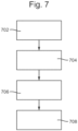
- a method of forming a heat exchanger structure is shown as involving a first step 702 of defining a repeating unit, a second step 704 of defining an operational characteristic set for a heat exchanger structure, a third step 706 of determining the parameters of the repeating units which satisfy the operational characteristic set, and at a fourth step 708, forming the structure according to the parameters.
- defining the repeating unit includes providing the definition of the repeating unit R having a set of variable parameters including but not limited to: base plate size, base plate thickness, base plate shape, conduit upward extension (i.e. channel height), opening/conduit bore, conduit wall thickness, conduit inclination, footprint location, and in-channel orientation (i.e. which plane the conduits align with for a channel, determining counter flow or co flow).
- the operational characteristic set may define a number of constraints including but not limited to: a desired thermal transfer rate, a working fluid combination (e.g. air and air, oil and fuel, air and glycol), a given space into which the exchanger should fit, a channel height, and an allowable pressure drop across the heat exchanger.
- a working fluid combination e.g. air and air, oil and fuel, air and glycol
- the determination of the parameters of the unit R could be carried out, in light of the operational characteristics from step 704, using a number of fluid dynamic simulations of the heat exchanger. These simulations could be carried out iteratively, for example in combination with a genetic algorithm, to arrive at a solution.
- the output of such determinations would be a data file defining a suitable heat exchanger, the definition including the parameters for the unit R, and the number of R units along each of the three orthogonal axes (for example referring back to figure 6 , it can be seen that there are four units along the fore to aft axis, and five along the bottom to top axis, with the near to far number being hidden from view).
- the heat exchanger could be formed by issuing the data file to an additive layer manufacturing station.
- a manifold corresponding to the heat exchanger core, could be generated by the process.
- a data file defining such a manifold could thereby be issued to an additive manufacturing station, alongside the heat exchanger data file, to enable the entire heat exchanger to be formed.
- the heat exchanger may comprise channels in the form of a tubular cluster.
- a first group of tubes (odd tubes) would carry a first fluid
- a second group of tubes (even tubes) would carry a second fluid.
- a first set of conduits would provide interconnections between the odd tubes, with interconnecting conduits passing through an even tube.
- a second set of conduits would interconnect the even tubes, with interconnecting conduits passing through an odd tube.
- such tubular clusters could comprise linear tubes arranged in parallel.
- Such tubular clusters could comprise nested spirals of tubes.
- the example cores given so far have been in the form of planar or substantially planar layers and channels, formed by planar base plates stacked in parallel.
- the core may be provided by a plurality of curved channels which may be of a predetermined shape or curvature so as to be conformal with a further device.
- the further device could be a substantially cylindrical engine.
- channels could be substantially conformal with one another, so as to maintain an inter-plate separation.
Landscapes
- Engineering & Computer Science (AREA)
- Physics & Mathematics (AREA)
- Thermal Sciences (AREA)
- Mechanical Engineering (AREA)
- General Engineering & Computer Science (AREA)
- Chemical & Material Sciences (AREA)
- Manufacturing & Machinery (AREA)
- Materials Engineering (AREA)
- Heat-Exchange Devices With Radiators And Conduit Assemblies (AREA)
Claims (14)
- Wärmetauscher (100), umfassend:einen ersten Kanal (10) zum Herstellen einer Verbindung zwischen einem ersten Kanaleinlass (12) und einem ersten Kanalauslass (14);einen zweiten Kanal (20) zum Herstellen einer Verbindung zwischen einem zweiten Kanaleinlass (22) und einem zweiten Kanalauslass (24);einen dritten Kanal (30) zum Herstellen einer Verbindung zwischen einem dritten Kanaleinlass (32) und einem dritten Kanalauslass (34); undeine Vielzahl von ersten Leitungen (8), wobei jede erste Leitung den ersten Kanal und den dritten Kanal miteinander verbindet und dadurch eine erste Gruppe miteinander verbundener Kanäle definiert, wobei sich die erste Leitung durch den zweiten Kanal erstreckt, dadurch gekennzeichnet, dass die Vielzahl von ersten Leitungen in benachbarten Paaren angeordnet ist, wobei eine Leitung pro Paar angeordnet ist, um die Strömung zwischen Kanälen vom dritten Kanal zum ersten Kanal zu fördern, und die andere Leitung pro Paar angeordnet ist, um die Strömung zwischen Kanälen vom ersten Kanal zum dritten Kanal zu fördern.
- Wärmetauscher nach Anspruch 1, wobei jede erste Leitung (8) relativ zu einer Mittelachse geneigt ist, die durch den ersten Kanal (10) definiert ist, und dadurch angeordnet ist, um die Strömung zwischen Kanälen zu fördern.
- Wärmetauscher nach Anspruch 2, wobei die erste Leitung (8) eine längliche Querschnittsform aufweist.
- Wärmetauscher nach Anspruch 3, wobei die längliche Querschnittsform eine kürzere Seite S und eine längere Seite L definiert, wobei die längere Seite L im Wesentlichen an einer vorbestimmten Strömungsrichtung ausgerichtet ist.
- Wärmetauscher nach Anspruch 3 oder 4, wobei die längliche Querschnittsform eine kürzere Seite S und eine längere Seite L definiert, wobei die längere Seite L im Wesentlichen an der Neigung der ersten Leitung (8) ausgerichtet ist.
- Wärmetauscher nach einem der vorstehenden Ansprüche, ferner umfassend:einen vierten Kanal (40) zum Herstellen einer Verbindung zwischen einem vierten Kanaleinlass (42) und einem vierten Kanalauslass (44),eine zweite Leitung (9), die den zweiten Kanal (20) und den vierten Kanal (40) miteinander verbindet und dadurch eine zweite Gruppe miteinander verbundener Kanäle definiert, wobei sich die zweite Leitung durch den dritten Kanal (30) erstreckt.
- Wärmetauscher nach Anspruch 6, wobei die zweite Leitung (9) relativ zu einer Mittelachse geneigt ist, die durch den zweiten Kanal (20) definiert ist.
- Wärmetauscher nach Anspruch 6 oder 7, umfassend eine Vielzahl von zweiten Leitungen (9), die den zweiten Kanal (20) und den vierten Kanal (40) miteinander verbinden, wobei sich jede der zweiten Leitungen durch den dritten Kanal (30) erstreckt.
- Wärmetauscher nach Anspruch 8, wobei die Vielzahl von zweiten Leitungen (9) in benachbarten Paaren angeordnet ist, wobei eine Leitung pro Paar angeordnet ist, um die Strömung zwischen Kanälen vom vierten Kanal (40) zum zweiten (20) zu fördern, und die andere Leitung pro Paar angeordnet ist, um die Strömung zwischen Kanälen vom zweiten Kanal (20) zum vierten (40) zu fördern.
- Wärmetauscher nach Anspruch 9, wobei die ersten Leitungspaare (8) und die zweiten Leitungspaare (9) eine äquivalente Position im zweiten (20) bzw. dritten Kanal (30) einnehmen.
- Wärmetauscher nach einem der Ansprüche 6 bis 10, umfassend eine obere Platte (6) und eine Vielzahl von Grundplatten (26), die zwischen einem Paar Seitenwände (5) montiert sind, wobeider erste Kanal (10) zwischen der oberen Platte, einer ersten Grundplatte und einem Abschnitt der Seitenwände definiert istder zweite Kanal (20) zwischen der ersten Grundplatte, der zweiten Grundplatte und einem Abschnitt der Seitenwände definiert ist,der dritte Kanal (30) zwischen der zweiten Grundplatte, der dritten Grundplatte und einem Abschnitt der Seitenwände definiert ist undder vierte Kanal (40) zwischen der dritten Grundplatte, einer vierten Grundplatte und einem Abschnitt der Seitenwände definiert ist.
- Wärmetauscher nach Anspruch 11, wobei der erste (10) und der dritte Kanal (30), die in Fluidverbindung stehen, angeordnet sind, um ein erstes Fluid in einer ersten Strömungsrichtung zu transportieren, und wobei der zweite (20) und der vierte Kanal (40), die in Fluidverbindung stehen, angeordnet sind, um ein zweites Fluid in einer zweiten Strömungsrichtung zu transportieren.
- Wärmetauscher nach Anspruch 12, ferner umfassend zu einem ersten Ende hin:einen ersten Fluideintrittsverteiler (2), der die Einlässe des ersten (10) und dritten Kanals (30) mit einer gemeinsamen ersten Fluideinlassöffnung verbindet, undeinen zweiten Fluideinlassverteiler, der die Auslässe des zweiten (20) und vierten Kanals (40) mit einer gemeinsamen zweiten Fluidauslassöffnung verbindet;und zu einem zweiten Ende hin:einen ersten Fluidausgangsverteiler (4), der die Auslässe des ersten und dritten Kanals mit einer gemeinsamen ersten Fluidauslassöffnung verbindet, undeinen zweiten Fluidausgangsverteiler, der die Einlässe des zweiten und vierten Kanals mit einer gemeinsamen zweiten Fluidauslassöffnung verbindet.
- Verfahren zum Wärmeaustausch, umfassend
Bereitstellen eines Wärmetauschers nach einem der vorstehenden Ansprüche, Bewirken, dass ein Kühlmittel durch den ersten und den zweiten Kanal strömt, Bewirken, dass ein Arbeitsfluid durch den dritten Kanal strömt.
Applications Claiming Priority (4)
| Application Number | Priority Date | Filing Date | Title |
|---|---|---|---|
| EP18160938.9A EP3537086A1 (de) | 2018-03-09 | 2018-03-09 | Wärmetauscher |
| GB1803776.2A GB2571774B (en) | 2018-03-09 | 2018-03-09 | Heat exchanger |
| GB1814115.0A GB2576748B (en) | 2018-08-30 | 2018-08-30 | Heat exchanger |
| PCT/GB2019/050653 WO2019171077A1 (en) | 2018-03-09 | 2019-03-08 | Heat exchanger |
Publications (2)
| Publication Number | Publication Date |
|---|---|
| EP3762671A1 EP3762671A1 (de) | 2021-01-13 |
| EP3762671B1 true EP3762671B1 (de) | 2023-08-16 |
Family
ID=65686901
Family Applications (1)
| Application Number | Title | Priority Date | Filing Date |
|---|---|---|---|
| EP19709556.5A Active EP3762671B1 (de) | 2018-03-09 | 2019-03-08 | Wärmetauscher |
Country Status (5)
| Country | Link |
|---|---|
| US (1) | US11592243B2 (de) |
| EP (1) | EP3762671B1 (de) |
| JP (1) | JP7052090B2 (de) |
| ES (1) | ES2956274T3 (de) |
| WO (1) | WO2019171077A1 (de) |
Families Citing this family (1)
| Publication number | Priority date | Publication date | Assignee | Title |
|---|---|---|---|---|
| IT201800010006A1 (it) * | 2018-11-02 | 2020-05-02 | Sumitomo Riko Co Ltd | Scambiatore di calore interno |
Family Cites Families (17)
| Publication number | Priority date | Publication date | Assignee | Title |
|---|---|---|---|---|
| FR2262550B1 (de) * | 1974-03-01 | 1976-10-08 | Lorraine Carbone | |
| WO2000052411A1 (en) | 1999-03-04 | 2000-09-08 | Ebara Corporation | Plate type heat exchanger |
| CA2328312C (en) | 2000-12-14 | 2010-12-07 | Herbert Rittberger | Heat exchanger |
| JPWO2004025207A1 (ja) | 2002-09-10 | 2006-01-12 | ジーエーシー株式会社 | 熱交換器およびその製造方法 |
| DE102006018709B3 (de) * | 2006-04-20 | 2007-10-11 | Nft Nanofiltertechnik Gmbh | Wärmetauscher |
| EP2275198A1 (de) | 2006-05-11 | 2011-01-19 | Corning Incorporated | Mikrofluidischer Verteiler |
| WO2008139651A1 (ja) * | 2007-05-02 | 2008-11-20 | Kanken Techno Co., Ltd. | 熱交換器およびこれを用いたガス処理装置 |
| US8678076B2 (en) | 2007-11-16 | 2014-03-25 | Christopher R. Shore | Heat exchanger with manifold strengthening protrusion |
| US8028410B2 (en) | 2008-12-08 | 2011-10-04 | Randy Thompson | Gas turbine regenerator apparatus and method of manufacture |
| JP5420970B2 (ja) | 2009-05-22 | 2014-02-19 | 株式会社ティラド | 熱交換器 |
| WO2011068470A1 (en) | 2009-12-02 | 2011-06-09 | National University Of Singapore | An enhanced heat sink |
| US9863716B2 (en) * | 2013-07-26 | 2018-01-09 | Hamilton Sundstrand Corporation | Heat exchanger with embedded heat pipes |
| US9777973B2 (en) * | 2013-09-20 | 2017-10-03 | Promix Solutions Ag | Device for mixing and heat exchange |
| CN104389683A (zh) | 2014-11-05 | 2015-03-04 | 中国船舶重工集团公司第七�三研究所 | 紧凑型回热器 |
| JP2017048961A (ja) | 2015-09-01 | 2017-03-09 | 持田 裕美 | 熱交換装置、熱交換方法 |
| EP3150952A1 (de) | 2015-10-02 | 2017-04-05 | Alfa Laval Corporate AB | Wärmetauschplatte und plattenwärmetauscher |
| US10422585B2 (en) * | 2017-09-22 | 2019-09-24 | Honeywell International Inc. | Heat exchanger with interspersed arrangement of cross-flow structures |
-
2019
- 2019-03-08 ES ES19709556T patent/ES2956274T3/es active Active
- 2019-03-08 EP EP19709556.5A patent/EP3762671B1/de active Active
- 2019-03-08 US US16/976,217 patent/US11592243B2/en active Active
- 2019-03-08 WO PCT/GB2019/050653 patent/WO2019171077A1/en not_active Ceased
- 2019-03-08 JP JP2020570653A patent/JP7052090B2/ja active Active
Also Published As
| Publication number | Publication date |
|---|---|
| US20210003352A1 (en) | 2021-01-07 |
| WO2019171077A1 (en) | 2019-09-12 |
| US11592243B2 (en) | 2023-02-28 |
| ES2956274T3 (es) | 2023-12-18 |
| JP2021516326A (ja) | 2021-07-01 |
| JP7052090B2 (ja) | 2022-04-11 |
| EP3762671A1 (de) | 2021-01-13 |
Similar Documents
| Publication | Publication Date | Title |
|---|---|---|
| US11965699B2 (en) | Heat exchangers | |
| US4401155A (en) | Heat exchanger with extruded flow channels | |
| EP3800417A1 (de) | Wärmetauscher mit verschachtelten verteilern und geschichtetem kern | |
| AU2004236275B2 (en) | Heat exchanger core | |
| EP3683531B1 (de) | Kreuzstromwärmetauscher | |
| EP3762672B1 (de) | Wärmetauscher | |
| US11280554B2 (en) | Fractal heat exchanger with bypass | |
| US12038236B2 (en) | Fractal heat exchanger | |
| EP3537086A1 (de) | Wärmetauscher | |
| US11248854B2 (en) | Heat exchanger | |
| EP3762671B1 (de) | Wärmetauscher | |
| GB2571774A (en) | Heat exchanger | |
| GB2571776A (en) | Heat exchanger | |
| EP3537087A1 (de) | Wärmetauscher | |
| GB2576748A (en) | Heat exchanger | |
| EP4477984B1 (de) | Kopf zum leiten von fluid zu und von einem wärmetauscherkörper | |
| JP6819482B2 (ja) | マイクロチャンネル熱交換器 | |
| CN117146619A (zh) | 一种交叉流换热器 |
Legal Events
| Date | Code | Title | Description |
|---|---|---|---|
| STAA | Information on the status of an ep patent application or granted ep patent |
Free format text: STATUS: UNKNOWN |
|
| STAA | Information on the status of an ep patent application or granted ep patent |
Free format text: STATUS: THE INTERNATIONAL PUBLICATION HAS BEEN MADE |
|
| PUAI | Public reference made under article 153(3) epc to a published international application that has entered the european phase |
Free format text: ORIGINAL CODE: 0009012 |
|
| STAA | Information on the status of an ep patent application or granted ep patent |
Free format text: STATUS: REQUEST FOR EXAMINATION WAS MADE |
|
| 17P | Request for examination filed |
Effective date: 20200903 |
|
| AK | Designated contracting states |
Kind code of ref document: A1 Designated state(s): AL AT BE BG CH CY CZ DE DK EE ES FI FR GB GR HR HU IE IS IT LI LT LU LV MC MK MT NL NO PL PT RO RS SE SI SK SM TR |
|
| AX | Request for extension of the european patent |
Extension state: BA ME |
|
| DAV | Request for validation of the european patent (deleted) | ||
| DAX | Request for extension of the european patent (deleted) | ||
| STAA | Information on the status of an ep patent application or granted ep patent |
Free format text: STATUS: EXAMINATION IS IN PROGRESS |
|
| 17Q | First examination report despatched |
Effective date: 20211207 |
|
| GRAP | Despatch of communication of intention to grant a patent |
Free format text: ORIGINAL CODE: EPIDOSNIGR1 |
|
| STAA | Information on the status of an ep patent application or granted ep patent |
Free format text: STATUS: GRANT OF PATENT IS INTENDED |
|
| INTG | Intention to grant announced |
Effective date: 20230314 |
|
| RBV | Designated contracting states (corrected) |
Designated state(s): AL AT BE BG CH CY CZ DE DK EE ES FI FR GR HR HU IE IS IT LI LT LU LV MC MK MT NL NO PL PT RO RS SE SI SK SM TR |
|
| GRAS | Grant fee paid |
Free format text: ORIGINAL CODE: EPIDOSNIGR3 |
|
| GRAA | (expected) grant |
Free format text: ORIGINAL CODE: 0009210 |
|
| STAA | Information on the status of an ep patent application or granted ep patent |
Free format text: STATUS: THE PATENT HAS BEEN GRANTED |
|
| AK | Designated contracting states |
Kind code of ref document: B1 Designated state(s): AL AT BE BG CH CY CZ DE DK EE ES FI FR GR HR HU IE IS IT LI LT LU LV MC MK MT NL NO PL PT RO RS SE SI SK SM TR |
|
| REG | Reference to a national code |
Ref country code: CH Ref legal event code: EP |
|
| REG | Reference to a national code |
Ref country code: DE Ref legal event code: R096 Ref document number: 602019035059 Country of ref document: DE |
|
| REG | Reference to a national code |
Ref country code: IE Ref legal event code: FG4D |
|
| REG | Reference to a national code |
Ref country code: SE Ref legal event code: TRGR |
|
| REG | Reference to a national code |
Ref country code: LT Ref legal event code: MG9D |
|
| REG | Reference to a national code |
Ref country code: ES Ref legal event code: FG2A Ref document number: 2956274 Country of ref document: ES Kind code of ref document: T3 Effective date: 20231218 |
|
| REG | Reference to a national code |
Ref country code: NL Ref legal event code: MP Effective date: 20230816 |
|
| REG | Reference to a national code |
Ref country code: AT Ref legal event code: MK05 Ref document number: 1600438 Country of ref document: AT Kind code of ref document: T Effective date: 20230816 |
|
| PG25 | Lapsed in a contracting state [announced via postgrant information from national office to epo] |
Ref country code: GR Free format text: LAPSE BECAUSE OF FAILURE TO SUBMIT A TRANSLATION OF THE DESCRIPTION OR TO PAY THE FEE WITHIN THE PRESCRIBED TIME-LIMIT Effective date: 20231117 |
|
| PG25 | Lapsed in a contracting state [announced via postgrant information from national office to epo] |
Ref country code: IS Free format text: LAPSE BECAUSE OF FAILURE TO SUBMIT A TRANSLATION OF THE DESCRIPTION OR TO PAY THE FEE WITHIN THE PRESCRIBED TIME-LIMIT Effective date: 20231216 |
|
| PG25 | Lapsed in a contracting state [announced via postgrant information from national office to epo] |
Ref country code: RS Free format text: LAPSE BECAUSE OF FAILURE TO SUBMIT A TRANSLATION OF THE DESCRIPTION OR TO PAY THE FEE WITHIN THE PRESCRIBED TIME-LIMIT Effective date: 20230816 Ref country code: PT Free format text: LAPSE BECAUSE OF FAILURE TO SUBMIT A TRANSLATION OF THE DESCRIPTION OR TO PAY THE FEE WITHIN THE PRESCRIBED TIME-LIMIT Effective date: 20231218 Ref country code: NO Free format text: LAPSE BECAUSE OF FAILURE TO SUBMIT A TRANSLATION OF THE DESCRIPTION OR TO PAY THE FEE WITHIN THE PRESCRIBED TIME-LIMIT Effective date: 20231116 Ref country code: NL Free format text: LAPSE BECAUSE OF FAILURE TO SUBMIT A TRANSLATION OF THE DESCRIPTION OR TO PAY THE FEE WITHIN THE PRESCRIBED TIME-LIMIT Effective date: 20230816 Ref country code: LV Free format text: LAPSE BECAUSE OF FAILURE TO SUBMIT A TRANSLATION OF THE DESCRIPTION OR TO PAY THE FEE WITHIN THE PRESCRIBED TIME-LIMIT Effective date: 20230816 Ref country code: LT Free format text: LAPSE BECAUSE OF FAILURE TO SUBMIT A TRANSLATION OF THE DESCRIPTION OR TO PAY THE FEE WITHIN THE PRESCRIBED TIME-LIMIT Effective date: 20230816 Ref country code: IS Free format text: LAPSE BECAUSE OF FAILURE TO SUBMIT A TRANSLATION OF THE DESCRIPTION OR TO PAY THE FEE WITHIN THE PRESCRIBED TIME-LIMIT Effective date: 20231216 Ref country code: HR Free format text: LAPSE BECAUSE OF FAILURE TO SUBMIT A TRANSLATION OF THE DESCRIPTION OR TO PAY THE FEE WITHIN THE PRESCRIBED TIME-LIMIT Effective date: 20230816 Ref country code: GR Free format text: LAPSE BECAUSE OF FAILURE TO SUBMIT A TRANSLATION OF THE DESCRIPTION OR TO PAY THE FEE WITHIN THE PRESCRIBED TIME-LIMIT Effective date: 20231117 Ref country code: FI Free format text: LAPSE BECAUSE OF FAILURE TO SUBMIT A TRANSLATION OF THE DESCRIPTION OR TO PAY THE FEE WITHIN THE PRESCRIBED TIME-LIMIT Effective date: 20230816 Ref country code: AT Free format text: LAPSE BECAUSE OF FAILURE TO SUBMIT A TRANSLATION OF THE DESCRIPTION OR TO PAY THE FEE WITHIN THE PRESCRIBED TIME-LIMIT Effective date: 20230816 |
|
| PG25 | Lapsed in a contracting state [announced via postgrant information from national office to epo] |
Ref country code: PL Free format text: LAPSE BECAUSE OF FAILURE TO SUBMIT A TRANSLATION OF THE DESCRIPTION OR TO PAY THE FEE WITHIN THE PRESCRIBED TIME-LIMIT Effective date: 20230816 |
|
| PG25 | Lapsed in a contracting state [announced via postgrant information from national office to epo] |
Ref country code: SM Free format text: LAPSE BECAUSE OF FAILURE TO SUBMIT A TRANSLATION OF THE DESCRIPTION OR TO PAY THE FEE WITHIN THE PRESCRIBED TIME-LIMIT Effective date: 20230816 Ref country code: RO Free format text: LAPSE BECAUSE OF FAILURE TO SUBMIT A TRANSLATION OF THE DESCRIPTION OR TO PAY THE FEE WITHIN THE PRESCRIBED TIME-LIMIT Effective date: 20230816 Ref country code: EE Free format text: LAPSE BECAUSE OF FAILURE TO SUBMIT A TRANSLATION OF THE DESCRIPTION OR TO PAY THE FEE WITHIN THE PRESCRIBED TIME-LIMIT Effective date: 20230816 Ref country code: DK Free format text: LAPSE BECAUSE OF FAILURE TO SUBMIT A TRANSLATION OF THE DESCRIPTION OR TO PAY THE FEE WITHIN THE PRESCRIBED TIME-LIMIT Effective date: 20230816 Ref country code: CZ Free format text: LAPSE BECAUSE OF FAILURE TO SUBMIT A TRANSLATION OF THE DESCRIPTION OR TO PAY THE FEE WITHIN THE PRESCRIBED TIME-LIMIT Effective date: 20230816 Ref country code: SK Free format text: LAPSE BECAUSE OF FAILURE TO SUBMIT A TRANSLATION OF THE DESCRIPTION OR TO PAY THE FEE WITHIN THE PRESCRIBED TIME-LIMIT Effective date: 20230816 |
|
| REG | Reference to a national code |
Ref country code: DE Ref legal event code: R097 Ref document number: 602019035059 Country of ref document: DE |
|
| PLBE | No opposition filed within time limit |
Free format text: ORIGINAL CODE: 0009261 |
|
| STAA | Information on the status of an ep patent application or granted ep patent |
Free format text: STATUS: NO OPPOSITION FILED WITHIN TIME LIMIT |
|
| 26N | No opposition filed |
Effective date: 20240517 |
|
| PG25 | Lapsed in a contracting state [announced via postgrant information from national office to epo] |
Ref country code: SI Free format text: LAPSE BECAUSE OF FAILURE TO SUBMIT A TRANSLATION OF THE DESCRIPTION OR TO PAY THE FEE WITHIN THE PRESCRIBED TIME-LIMIT Effective date: 20230816 |
|
| REG | Reference to a national code |
Ref country code: CH Ref legal event code: PL |
|
| PG25 | Lapsed in a contracting state [announced via postgrant information from national office to epo] |
Ref country code: BG Free format text: LAPSE BECAUSE OF FAILURE TO SUBMIT A TRANSLATION OF THE DESCRIPTION OR TO PAY THE FEE WITHIN THE PRESCRIBED TIME-LIMIT Effective date: 20230816 |
|
| PG25 | Lapsed in a contracting state [announced via postgrant information from national office to epo] |
Ref country code: LU Free format text: LAPSE BECAUSE OF NON-PAYMENT OF DUE FEES Effective date: 20240308 |
|
| PG25 | Lapsed in a contracting state [announced via postgrant information from national office to epo] |
Ref country code: MC Free format text: LAPSE BECAUSE OF FAILURE TO SUBMIT A TRANSLATION OF THE DESCRIPTION OR TO PAY THE FEE WITHIN THE PRESCRIBED TIME-LIMIT Effective date: 20230816 |
|
| PG25 | Lapsed in a contracting state [announced via postgrant information from national office to epo] |
Ref country code: MC Free format text: LAPSE BECAUSE OF FAILURE TO SUBMIT A TRANSLATION OF THE DESCRIPTION OR TO PAY THE FEE WITHIN THE PRESCRIBED TIME-LIMIT Effective date: 20230816 Ref country code: LU Free format text: LAPSE BECAUSE OF NON-PAYMENT OF DUE FEES Effective date: 20240308 Ref country code: BG Free format text: LAPSE BECAUSE OF FAILURE TO SUBMIT A TRANSLATION OF THE DESCRIPTION OR TO PAY THE FEE WITHIN THE PRESCRIBED TIME-LIMIT Effective date: 20230816 |
|
| REG | Reference to a national code |
Ref country code: BE Ref legal event code: MM Effective date: 20240331 |
|
| PG25 | Lapsed in a contracting state [announced via postgrant information from national office to epo] |
Ref country code: BE Free format text: LAPSE BECAUSE OF NON-PAYMENT OF DUE FEES Effective date: 20240331 |
|
| PG25 | Lapsed in a contracting state [announced via postgrant information from national office to epo] |
Ref country code: IE Free format text: LAPSE BECAUSE OF NON-PAYMENT OF DUE FEES Effective date: 20240308 |
|
| PG25 | Lapsed in a contracting state [announced via postgrant information from national office to epo] |
Ref country code: IE Free format text: LAPSE BECAUSE OF NON-PAYMENT OF DUE FEES Effective date: 20240308 Ref country code: BE Free format text: LAPSE BECAUSE OF NON-PAYMENT OF DUE FEES Effective date: 20240331 Ref country code: CH Free format text: LAPSE BECAUSE OF NON-PAYMENT OF DUE FEES Effective date: 20240331 |
|
| PGFP | Annual fee paid to national office [announced via postgrant information from national office to epo] |
Ref country code: ES Payment date: 20250401 Year of fee payment: 7 |
|
| PG25 | Lapsed in a contracting state [announced via postgrant information from national office to epo] |
Ref country code: CY Free format text: LAPSE BECAUSE OF FAILURE TO SUBMIT A TRANSLATION OF THE DESCRIPTION OR TO PAY THE FEE WITHIN THE PRESCRIBED TIME-LIMIT; INVALID AB INITIO Effective date: 20190308 |
|
| PG25 | Lapsed in a contracting state [announced via postgrant information from national office to epo] |
Ref country code: HU Free format text: LAPSE BECAUSE OF FAILURE TO SUBMIT A TRANSLATION OF THE DESCRIPTION OR TO PAY THE FEE WITHIN THE PRESCRIBED TIME-LIMIT; INVALID AB INITIO Effective date: 20190308 |
|
| PGFP | Annual fee paid to national office [announced via postgrant information from national office to epo] |
Ref country code: SE Payment date: 20260219 Year of fee payment: 8 |
|
| PGFP | Annual fee paid to national office [announced via postgrant information from national office to epo] |
Ref country code: DE Payment date: 20260219 Year of fee payment: 8 |
|
| PGFP | Annual fee paid to national office [announced via postgrant information from national office to epo] |
Ref country code: IT Payment date: 20260219 Year of fee payment: 8 |
|
| PGFP | Annual fee paid to national office [announced via postgrant information from national office to epo] |
Ref country code: FR Payment date: 20260219 Year of fee payment: 8 |
|
| PGFP | Annual fee paid to national office [announced via postgrant information from national office to epo] |
Ref country code: TR Payment date: 20260223 Year of fee payment: 8 |