EP3762900B1 - Lokalisierte telezentrizität und fokusoptimierung für überlagerungsmetrologie - Google Patents
Lokalisierte telezentrizität und fokusoptimierung für überlagerungsmetrologie Download PDFInfo
- Publication number
- EP3762900B1 EP3762900B1 EP19785061.3A EP19785061A EP3762900B1 EP 3762900 B1 EP3762900 B1 EP 3762900B1 EP 19785061 A EP19785061 A EP 19785061A EP 3762900 B1 EP3762900 B1 EP 3762900B1
- Authority
- EP
- European Patent Office
- Prior art keywords
- alignment
- imaging system
- overlay
- images
- telecentricity
- Prior art date
- Legal status (The legal status is an assumption and is not a legal conclusion. Google has not performed a legal analysis and makes no representation as to the accuracy of the status listed.)
- Active
Links
Images




Classifications
-
- G—PHYSICS
- G01—MEASURING; TESTING
- G01B—MEASURING LENGTH, THICKNESS OR SIMILAR LINEAR DIMENSIONS; MEASURING ANGLES; MEASURING AREAS; MEASURING IRREGULARITIES OF SURFACES OR CONTOURS
- G01B11/00—Measuring arrangements characterised by the use of optical techniques
- G01B11/26—Measuring arrangements characterised by the use of optical techniques for measuring angles or tapers; for testing the alignment of axes
- G01B11/27—Measuring arrangements characterised by the use of optical techniques for measuring angles or tapers; for testing the alignment of axes for testing the alignment of axes
- G01B11/272—Measuring arrangements characterised by the use of optical techniques for measuring angles or tapers; for testing the alignment of axes for testing the alignment of axes using photoelectric detection means
-
- G—PHYSICS
- G01—MEASURING; TESTING
- G01B—MEASURING LENGTH, THICKNESS OR SIMILAR LINEAR DIMENSIONS; MEASURING ANGLES; MEASURING AREAS; MEASURING IRREGULARITIES OF SURFACES OR CONTOURS
- G01B11/00—Measuring arrangements characterised by the use of optical techniques
- G01B11/002—Measuring arrangements characterised by the use of optical techniques for measuring two or more coordinates
-
- G—PHYSICS
- G03—PHOTOGRAPHY; CINEMATOGRAPHY; ANALOGOUS TECHNIQUES USING WAVES OTHER THAN OPTICAL WAVES; ELECTROGRAPHY; HOLOGRAPHY
- G03F—PHOTOMECHANICAL PRODUCTION OF TEXTURED OR PATTERNED SURFACES, e.g. FOR PRINTING, FOR PROCESSING OF SEMICONDUCTOR DEVICES; MATERIALS THEREFOR; ORIGINALS THEREFOR; APPARATUS SPECIALLY ADAPTED THEREFOR
- G03F7/00—Photomechanical, e.g. photolithographic, production of textured or patterned surfaces, e.g. printing surfaces; Materials therefor, e.g. comprising photoresists; Apparatus specially adapted therefor
- G03F7/70—Microphotolithographic exposure; Apparatus therefor
- G03F7/70483—Information management; Active and passive control; Testing; Wafer monitoring, e.g. pattern monitoring
- G03F7/70605—Workpiece metrology
- G03F7/70616—Monitoring the printed patterns
- G03F7/70633—Overlay, i.e. relative alignment between patterns printed by separate exposures in different layers, or in the same layer in multiple exposures or stitching
-
- G—PHYSICS
- G03—PHOTOGRAPHY; CINEMATOGRAPHY; ANALOGOUS TECHNIQUES USING WAVES OTHER THAN OPTICAL WAVES; ELECTROGRAPHY; HOLOGRAPHY
- G03F—PHOTOMECHANICAL PRODUCTION OF TEXTURED OR PATTERNED SURFACES, e.g. FOR PRINTING, FOR PROCESSING OF SEMICONDUCTOR DEVICES; MATERIALS THEREFOR; ORIGINALS THEREFOR; APPARATUS SPECIALLY ADAPTED THEREFOR
- G03F7/00—Photomechanical, e.g. photolithographic, production of textured or patterned surfaces, e.g. printing surfaces; Materials therefor, e.g. comprising photoresists; Apparatus specially adapted therefor
- G03F7/70—Microphotolithographic exposure; Apparatus therefor
- G03F7/70483—Information management; Active and passive control; Testing; Wafer monitoring, e.g. pattern monitoring
- G03F7/70605—Workpiece metrology
- G03F7/70616—Monitoring the printed patterns
- G03F7/70641—Focus
-
- G—PHYSICS
- G03—PHOTOGRAPHY; CINEMATOGRAPHY; ANALOGOUS TECHNIQUES USING WAVES OTHER THAN OPTICAL WAVES; ELECTROGRAPHY; HOLOGRAPHY
- G03F—PHOTOMECHANICAL PRODUCTION OF TEXTURED OR PATTERNED SURFACES, e.g. FOR PRINTING, FOR PROCESSING OF SEMICONDUCTOR DEVICES; MATERIALS THEREFOR; ORIGINALS THEREFOR; APPARATUS SPECIALLY ADAPTED THEREFOR
- G03F7/00—Photomechanical, e.g. photolithographic, production of textured or patterned surfaces, e.g. printing surfaces; Materials therefor, e.g. comprising photoresists; Apparatus specially adapted therefor
- G03F7/70—Microphotolithographic exposure; Apparatus therefor
- G03F7/70483—Information management; Active and passive control; Testing; Wafer monitoring, e.g. pattern monitoring
- G03F7/70605—Workpiece metrology
- G03F7/70681—Metrology strategies
- G03F7/70683—Mark designs
-
- G—PHYSICS
- G03—PHOTOGRAPHY; CINEMATOGRAPHY; ANALOGOUS TECHNIQUES USING WAVES OTHER THAN OPTICAL WAVES; ELECTROGRAPHY; HOLOGRAPHY
- G03F—PHOTOMECHANICAL PRODUCTION OF TEXTURED OR PATTERNED SURFACES, e.g. FOR PRINTING, FOR PROCESSING OF SEMICONDUCTOR DEVICES; MATERIALS THEREFOR; ORIGINALS THEREFOR; APPARATUS SPECIALLY ADAPTED THEREFOR
- G03F9/00—Registration or positioning of originals, masks, frames, photographic sheets or textured or patterned surfaces, e.g. automatically
- G03F9/70—Registration or positioning of originals, masks, frames, photographic sheets or textured or patterned surfaces, e.g. automatically for microlithography
- G03F9/7003—Alignment type or strategy, e.g. leveling, global alignment
- G03F9/7023—Aligning or positioning in direction perpendicular to substrate surface
- G03F9/7034—Leveling
-
- G—PHYSICS
- G03—PHOTOGRAPHY; CINEMATOGRAPHY; ANALOGOUS TECHNIQUES USING WAVES OTHER THAN OPTICAL WAVES; ELECTROGRAPHY; HOLOGRAPHY
- G03F—PHOTOMECHANICAL PRODUCTION OF TEXTURED OR PATTERNED SURFACES, e.g. FOR PRINTING, FOR PROCESSING OF SEMICONDUCTOR DEVICES; MATERIALS THEREFOR; ORIGINALS THEREFOR; APPARATUS SPECIALLY ADAPTED THEREFOR
- G03F9/00—Registration or positioning of originals, masks, frames, photographic sheets or textured or patterned surfaces, e.g. automatically
- G03F9/70—Registration or positioning of originals, masks, frames, photographic sheets or textured or patterned surfaces, e.g. automatically for microlithography
- G03F9/7073—Alignment marks and their environment
- G03F9/7076—Mark details, e.g. phase grating mark, temporary mark
-
- G—PHYSICS
- G06—COMPUTING OR CALCULATING; COUNTING
- G06T—IMAGE DATA PROCESSING OR GENERATION, IN GENERAL
- G06T5/00—Image enhancement or restoration
- G06T5/50—Image enhancement or restoration using two or more images, e.g. averaging or subtraction
-
- G—PHYSICS
- G06—COMPUTING OR CALCULATING; COUNTING
- G06T—IMAGE DATA PROCESSING OR GENERATION, IN GENERAL
- G06T7/00—Image analysis
- G06T7/30—Determination of transform parameters for the alignment of images, i.e. image registration
- G06T7/33—Determination of transform parameters for the alignment of images, i.e. image registration using feature-based methods
-
- G—PHYSICS
- G06—COMPUTING OR CALCULATING; COUNTING
- G06T—IMAGE DATA PROCESSING OR GENERATION, IN GENERAL
- G06T7/00—Image analysis
- G06T7/70—Determining position or orientation of objects or cameras
- G06T7/73—Determining position or orientation of objects or cameras using feature-based methods
-
- G—PHYSICS
- G06—COMPUTING OR CALCULATING; COUNTING
- G06T—IMAGE DATA PROCESSING OR GENERATION, IN GENERAL
- G06T7/00—Image analysis
- G06T7/70—Determining position or orientation of objects or cameras
- G06T7/73—Determining position or orientation of objects or cameras using feature-based methods
- G06T7/74—Determining position or orientation of objects or cameras using feature-based methods involving reference images or patches
-
- H—ELECTRICITY
- H04—ELECTRIC COMMUNICATION TECHNIQUE
- H04N—PICTORIAL COMMUNICATION, e.g. TELEVISION
- H04N23/00—Cameras or camera modules comprising electronic image sensors; Control thereof
- H04N23/60—Control of cameras or camera modules
- H04N23/69—Control of means for changing angle of the field of view, e.g. optical zoom objectives or electronic zooming
-
- G—PHYSICS
- G06—COMPUTING OR CALCULATING; COUNTING
- G06T—IMAGE DATA PROCESSING OR GENERATION, IN GENERAL
- G06T2207/00—Indexing scheme for image analysis or image enhancement
- G06T2207/10—Image acquisition modality
- G06T2207/10016—Video; Image sequence
-
- G—PHYSICS
- G06—COMPUTING OR CALCULATING; COUNTING
- G06T—IMAGE DATA PROCESSING OR GENERATION, IN GENERAL
- G06T2207/00—Indexing scheme for image analysis or image enhancement
- G06T2207/10—Image acquisition modality
- G06T2207/10141—Special mode during image acquisition
- G06T2207/10148—Varying focus
-
- G—PHYSICS
- G06—COMPUTING OR CALCULATING; COUNTING
- G06T—IMAGE DATA PROCESSING OR GENERATION, IN GENERAL
- G06T2207/00—Indexing scheme for image analysis or image enhancement
- G06T2207/30—Subject of image; Context of image processing
- G06T2207/30108—Industrial image inspection
- G06T2207/30148—Semiconductor; IC; Wafer
Definitions
- the present disclosure relates generally to the field of overlay metrology and, more particularly, to localized alignment of overlay targets.
- Image-based overlay metrology may typically include determining relative offsets between two or more layers on a sample based on relative imaged positions of features of an overlay target in the different layers of interest. Accordingly, the accuracy of the overlay measurement may be sensitive to alignment errors of the overlay target in the metrology tool.
- Typical overlay metrology systems may align a sample once per wafer batch or measurement recipe. However, overlay measurements may be performed at various overlay targets distributed across a sample and the optimal alignment of each overlay target may not be the same due to sample variations, differences in target design, or the like. Accordingly, a single alignment of a sample may result in decreased overlay measurement precision due to localized variations of overlay targets. Therefore, it may be desirable to have systems and methods to efficiently align an overlay metrology system to any selected overlay target on a sample.
- US2017/184980 discloses a lithographic apparatus, device manufacturing method and associated data processing apparatus and computer program product.
- US2011/096981 describes focus finding and alignment using a split linear mask.
- JPH096017 discloses an alignment device.
- US2012/320359 describes a lithographic apparatus and device manufacturing method.
- WO2017/114652 discloses an alternative target design for metrology using modulation techniques.
- US2012123581 describes a metrology method and inspection apparatus, lithographic system and device manufacturing method.
- the present invention provides an overlay metrology system as recited in claim 1.
- the present invention further provides an overlay metrology method as recited in claim 14.
- Embodiments of the present disclosure are directed to systems and methods for site-by-site alignment of an overlay metrology tool.
- Alignment errors such as, but not limited to, focus errors, telecentricity errors, or centering errors may negatively impact the measurement accuracy of image-based overlay metrology.
- defocus of a sample may decrease measurement precision due a loss of image contrast.
- asymmetries of an overlay target may induce focus-dependent overlay errors during measurement.
- telecentricity errors may induce tool-induced shift (TIS), which may directly negatively impact overlay determinations.
- TIS tool-induced shift
- alignment data may include data indicative of a difference between the focal positions at which the alignment images were captured and a nominal or target focal position (e.g., a focus error).
- focus data may include image contrast metrics of the alignment images indicative of focus errors in the alignment images.
- the alignment data may include lateral shifts of imaged features and/or magnification variations as a function of focal position. Accordingly, this alignment data may be indicative of telecentricity errors of the sample within the imaging system.
- the alignment data may be used to accurately position (e.g., center) selected features of the overlay target within a field of view of the imaging system.
- Additional embodiments of the present disclosure are directed to aligning the sample in the imaging system within selected alignment tolerances (e.g., focus tolerances, telecentricity tolerances, centering tolerances, or the like) based on the alignment data.
- selected alignment tolerances e.g., focus tolerances, telecentricity tolerances, centering tolerances, or the like
- an overlay metrology tool may be aligned to any number of selected overlay targets on a sample prior to generating overlay measurements on the selected overlay targets to facilitate robust and accurate overlay measurements for each target.
- the sample (or one or more features one a selected layer of the sample) may be aligned to be in focus on a selected camera of the imaging system based on the focus data.
- one or more elements of the imaging system such as, but not limited to a sample stage, a position of an objective lens, or the like may be adjusted to focus the sample within the selected focus tolerances (e.g., a range of focus positions providing a desired image quality).
- one or more components of the imaging system such as, but not limited to, an aperture stop may be adjusted to provide telecentric imaging of the sample within the selected telecentricity tolerances (e.g., allowable deviations of the lateral position, magnification, or the like of imaged features).
- Additional embodiments are directed to capturing a measurement of the sample after aligning the sample based on the alignment data. Further embodiments are directed to determining overlay between two or more layers of the sample based on the measurement image. In this regard, a highly precise overlay measurement may be generated for each overlay target.
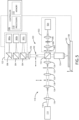
- FIG. 1A is a conceptual view illustrating an image-based overlay metrology system 100 suitable for site-by-site alignment, in accordance with one or more embodiments of the present disclosure.
- the overlay metrology system 100 may determine overlay (e.g., overlay errors) between two or more layers of a sample 102 based on images of overlay targets distributed across the sample 102.
- the overlay metrology system 100 includes a telecentric imaging system 104 to generate one or more images of the sample 102 and a controller 106 to determine overlay of two or more layers of the sample 102 based on images from the imaging system 104.
- overlay metrology system 100 may include a sample stage 108 for positioning selected portions of the sample 102 (e.g., selected overlay targets) within a field of view of the imaging system 104 for the determination of overlay.
- the sample stage 108 may include any device suitable for positioning the sample 102 within the overlay metrology system 100.
- the sample stage 108 may include any combination of linear translation stages, rotational stages, tip/tilt stages or the like.
- the imaging system 104 includes one or more adjustable components suitable for aligning a portion of the sample 102 within the selected alignment tolerances.
- the adjustable components may include, but are not limited to, the sample stage 108, one or more aperture stops, or one or more additional translation stages suitable for adjusting optical components.
- the controller 106 includes one or more processors 110 configured to execute program instructions maintained on a memory medium 112.
- the one or more processors 110 of controller 106 may execute any of the various process steps described throughout the present disclosure.
- the controller 106 may be communicatively coupled to any component of the overlay metrology system 100.
- the controller 106 may be communicatively coupled to the imaging system 104 to receive images from the imaging system 104 and/or control the adjustable components of the imaging system 104 to align the sample 102 within selected alignment tolerances.
- the controller 106 may determine overlay associated with two or more layers of the sample 102 based on images received from the imaging system 104.
- the one or more processors 110 of a controller 106 may include any processing element known in the art.
- the one or more processors 110 may include any microprocessor-type device configured to execute algorithms and/or instructions.
- the one or more processors 110 may consist of a desktop computer, mainframe computer system, workstation, image computer, parallel processor, or any other computer system (e.g., networked computer) configured to execute a program configured to operate the overlay metrology system 100, as described throughout the present disclosure.
- processor may be broadly defined to encompass any device having one or more processing elements, which execute program instructions from a non-transitory memory medium 112.
- controller 106 may include one or more controllers housed in a common housing or within multiple housings. In this way, any controller or combination of controllers may be separately packaged as a module suitable for integration into overlay metrology system 100. Further, the controller 106 may analyze data received from the detector assembly 122 and feed the data to additional components within the overlay metrology system 100 or external to the overlay metrology system 100.
- the memory medium 112 may include any storage medium known in the art suitable for storing program instructions executable by the associated one or more processors 110.
- the memory medium 112 may include a non-transitory memory medium.
- the memory medium 112 may include, but is not limited to, a read-only memory, a random access memory, a magnetic or optical memory device (e.g., disk), a magnetic tape, a solid state drive and the like. It is further noted that memory medium 112 may be housed in a common controller housing with the one or more processors 110. In one embodiment, the memory medium 112 may be located remotely with respect to the physical location of the one or more processors 110 and controller 106.
- the one or more processors 110 of controller 106 may access a remote memory (e.g., server), accessible through a network (e.g., internet, intranet and the like). Therefore, the above description should not be interpreted as a limitation on the present invention but merely an illustration.
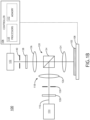
- FIG. 1B is a conceptual view of an imaging overlay metrology system 100, in accordance with one or more embodiments of the present disclosure.
- the overlay metrology system 100 includes an illumination source 114 to generate an illumination beam 116, an illumination pathway 118 to direct the illumination beam 116 to the sample 102 mounted on the sample stage 108, a collection pathway 120 to direct radiation emanating from the sample 102 to a detector assembly 122.
- the detector assembly 122 may include at least one imaging detector suitable for capturing an image of the sample 102.
- the illumination beam 116 may include one or more selected wavelengths of light including, but not limited to, vacuum ultraviolet radiation (VUV), deep ultraviolet radiation (DUV), ultraviolet (UV) radiation, visible radiation, or infrared (IR) radiation.
- the illumination source 114 may further generate an illumination beam 116 including any range of selected wavelengths.
- the illumination source 114 may include a spectrally-tunable illumination source to generate an illumination beam 116 having a tunable spectrum.
- the illumination source 114 may further produce an illumination beam 116 having any temporal profile.
- the illumination source 114 may produce a continuous illumination beam 116, a pulsed illumination beam 116, or a modulated illumination beam 116.
- the illumination beam 116 may be delivered from the illumination source 114 via free-space propagation or guided light (e.g. an optical fiber, a light pipe, or the like).
- the illumination source 114 may include any type of illumination source suitable for providing an illumination beam 116.
- the illumination source 114 is a laser source.
- the illumination source 114 may include, but is not limited to, one or more narrowband laser sources, a broadband laser source, a supercontinuum laser source, a white light laser source, or the like.
- the illumination source 114 may provide an illumination beam 116 having high coherence (e.g., high spatial coherence and/or temporal coherence).
- the illumination source 114 includes a laser-sustained plasma (LSP) source.
- LSP laser-sustained plasma
- the illumination source 114 directs the illumination beam 116 to a sample 102 via the illumination pathway 118.
- the illumination pathway 118 may include an objective lens 124 to focus the illumination beam 116 onto the sample 102.
- the illumination pathway 118 may include one or more illumination pathway lenses 126 or illumination conditioning components 128 suitable for modifying and/or conditioning the illumination beam 116.
- the one or more illumination conditioning components 128 may include, but are not limited to, one or more polarizers, one or more filters, one or more beam splitters, one or more diffusers, one or more homogenizers, one or more apodizers, or one or more beam shapers.
- the illumination pathway 118 may include aperture stops to control the angle of illumination on the sample 102 and/or field stops to control the spatial extent of illumination on the sample 102.
- the illumination pathway 118 includes an illumination aperture stop 130 to provide telecentric illumination of the sample.
- the illumination aperture stop 130 may be located at a plane conjugate to the back focal plane of the objective lens 124 and/or a tube lens (not shown).
- the illumination pathway 118 includes an illumination field stop 132 to control the spatial extent of illumination on the sample 102 to be directed to the sample 102.
- the illumination field stop 132 may be located at a plane conjugate to the sample 102.
- the illumination pathway 118 may include any number of illumination pathway lenses 126 that facilitate placement of the illumination aperture stop 130 and the illumination field stop 132 at convenient locations.
- the collection pathway 120 may include any number of optical elements to collect radiation emanating from the sample (e.g., in response to the illumination beam 116) and direct the collected radiation to the detector assembly 122.
- the collection pathway 120 includes a beamsplitter 134 oriented such that the objective lens 124 may simultaneously direct the illumination beam 116 to the sample 102 and collect radiation from the sample 102.
- the collection pathway 120 may further include one or more collection pathway lenses 136 and/or conditioning collection components 138 suitable for modifying and/or conditioning the radiation from the sample 102 such as, but not limited to, one or more filters, one or more polarizers, or one or more beam blocks.
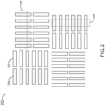
- first-layer features 204 and/or the second-layer features 206 may be oriented to facilitate overlay measurements in orthogonal directions.
- the overlay target 202 may include four quadrants in which a portion first-layer features 204 and the second-layer features 206 are aligned along a first direction and a portion of the first-layer features 204 and the second-layer features 206 are oriented along a second direction orthogonal to the first direction.
- the first-layer features 204 and the second-layer features 206 may be, but are not required to be, segmented.
- Alignment errors may be associated with any type of alignment metric that may impact an overlay measurement from an overlay target (e.g., overlay target 202) such as, but not limited to, focus errors and telecentricity errors.
- focus errors may be associated with a deviation of the height of the overlay target with respect to a nominal focal position such that an image of the overlay target is out of focus.
- Defocus in a measurement image may negatively impact overlay measurements in a variety of ways such as, but not limited to, reducing the image contrast and the measurement precision of feature edges.
- telecentricity errors may give rise to TIS.
- the apparent positions of features may appear to laterally shift as a function of focal position in the imaging system 104, which may induce overlay offset errors.
- the imaging system 104 generates two or more alignment images from the imaging system 104 at different focal positions for each selected overlay measurement site (e.g., each selected overlay target). It is recognized herein that alignment images at two or more focal positions may provide sufficient information to accurately determine alignment errors (e.g., focus errors, telecentricity errors, centering errors, or the like) and thus facilitate mitigation of the alignment errors on a site-by-site basis.
- the controller 106 may then generate alignment data based on the alignment images and then direct the imaging system 104 to align the sample 102 within selected alignment tolerances in the case that the sample 102 is outside of the alignment tolerances at the selected site. Once the imaging system 104 is aligned, the imaging system 104 may generate a measurement image and the controller 106 may provide overlay measurements for two or more layers of the sample 102 based on the measurement image.
- the focal position of sample 102 within the imaging system 104 may be controlled using any combination of elements.
- the focal position of the sample 102 may be adjusted via the sample stage 108.
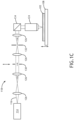
- the focal position of the sample 102 may be controlled by adjusting a position of one or more elements of the collection pathway 120 such as, but not limited to, the objective lens 124 or the imaging detector 302.
- FIG. 4 is a conceptual view of an imaging system 104 suitable for capturing simultaneous alignment images, in accordance with the invention.
- the detector assembly 122 includes two or more imaging detectors configured to simultaneously capture images at selected focal positions.
- the detector assembly 122 may include three imaging detectors 302a-c to simultaneously capture three images of the sample 102 at three selected focal positions.
- the detector assembly 122 may further include detector optical elements to split and direct the radiation emanating from the sample 102 along multiple paths to be captured by the imaging detectors 302 such as, but not limited to, one or more beamsplitters 304, one or more prisms 306, one or more mirrors (not shown), or one or more detector lenses (not shown).
- the detector assembly 122 may be configured to capture images at any selected focal positions.
- the detector assembly 122 includes one imaging detector configured to capture images at a nominal (e.g., ideal) focal position at which the sample 102 is expected to be aligned and one or more additional imaging detectors configured to capture images at selected offsets from the nominal focal position.
- imaging detector 302b may be configured to capture images at the nominal focal position
- imaging detector 302a may be configured to capture images at a selected positive offset from the nominal focal position
- imaging detector 302c may be configured to capture images at a selected negative offset from the nominal focal position.
- the nominal focal position may additionally correspond to an aberrationcorrecting imaging configuration based on the specifications of the objective lens 124.
- the alignment data extracted from the alignment images may include any type of data suitable for providing correctables to align a selected overlay target within the imaging system 104.
- the alignment data includes focus data indicative of the relative defocus of the alignment images such as, but not limited to the image contrast. Such data may then be used (e.g., by the controller 106) to accurately adjust the focal position of the sample such that the selected overlay target is in focus on a selected camera of the detector assembly 122 (e.g., the single imaging detector 302 of FIG. 3 , the nominal imaging detector 302b of FIG. 4 , or the like).
- images of an overlay target may typically include a high image contrast including the first-layer features 204 and the second-layer features 206 visible against a background.
- the image contrast may typically be highest when the overlay target is in focus and may typically decrease with increasing defocus.
- Image contrast data associated with a difference in image intensity (e.g., pixel value) between the features of the overlay target and the background for each alignment image may thus be indicative of the relative defocus associated with each alignment image.
- focus data associated with two or more alignment images may be utilized (e.g., by the controller 106) to adjust a focal position for the overlay target such that the selected overlay target is in focus within selected focus tolerances (e.g., a selected range of focal positions providing a desired image quality, or the like) on a selected camera of the detector assembly 122 (e.g., the single imaging detector 302 of FIG. 3 , the nominal imaging detector 302b of FIG. 4 , or the like).
- selected focus tolerances e.g., a selected range of focal positions providing a desired image quality, or the like
- the alignment data includes telecentricity data indicative of a telecentricity error of the selected overlay target (e.g., overlay target 202).
- telecentricity error may manifest as a variation of feature size (e.g., variation of image magnification) as a function of focal position.
- telecentricity error may manifest as a lateral shift of features when imaged at different focal positions.
- telecentricity data may include relative location information of features in the overlay target. Further, the magnitude and/or the direction of the lateral shifts may then be used to correct the telecentricity errors.
- Telecentricity errors may be determined based on two or more alignment images captured at different focal positions either sequentially or simultaneously.
- the telecentricity data may include position and/or orientation information of selected features of the overlay target in each of the alignment images.
- the position and/or orientation information may be represented in terms of the pixel locations of the features.
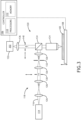
- FIG. 5 is a conceptual view of a pattern projector 502 integrated into an imaging system 104, in accordance with one or more embodiments of the present disclosure.
- the pattern projector 502 includes a projector illumination source 504 configured to generate a beam of illumination, a pattern mask 506, and projection optics 508 to generate an image of the pattern mask 506 onto the imaging detectors 302.
- illumination passed by the pattern mask 506 may be directed by the beamsplitter 134 directly to the imaging detectors 302.
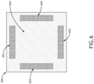
- the pattern mask 506 includes grating structures oriented along orthogonal directions to facilitate monitoring of the imaging detectors 302 along the orthogonal directions.
- a pattern mask 506 may include at least one grating pattern with elements distributed along a first direction and at least one grating pattern with elements distributed along a second direction orthogonal to the first direction.
- the patterns 602 may further be configured to be projected onto any portion of the imaging detectors 302.
- the patterns 602 may be placed along outer regions of the pattern mask 506, leaving a central open area 604 for the imaging of the selected overlay target.
- FIG. 7 is a conceptual image 700 of an overlay target 702 superimposed with projected images of patterns 602 from the pattern mask 506 of FIG. 6 , in accordance with one or more embodiments of the present disclosure.
- the image 700 of FIG. 7 may be captured by any imaging detector of the detector assembly 122 (e.g., imaging detector 302 of FIG. 4 , or any of imaging detectors 302a-c) of FIG. 5 ).
- the overlay target 702 is visible in the central portion of the image 700, while the patterns 602 are visible on outer regions of the image 700. Further, the patterns 602 may be projected to portions of the imaging detectors of the detector assembly 122 not associated with the image of the overlay target 702. For example, the overlay target 702 is visible as black features on a white background, where the boundaries 704 of the white background (e.g., a square in FIG. 7 ) may be controlled using the collection field stop of the imaging system 104.
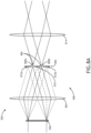
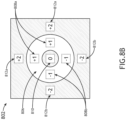
- FIGS. 8A and 8B illustrate projection optics 508 with a darkfield filter configured to pass only first-order diffraction (e.g., +/- 1 diffraction orders) from the pattern mask 506.
- FIG. 8A is a conceptual view of projection optics 508 including a darkfield stop 802, in accordance with one or more embodiments of the present disclosure.
- FIG. 8B is a top view of a darkfield stop 802 configured to select first-order diffraction (e.g., +/- 1 diffraction orders), in accordance with one or more embodiments of the present disclosure.
- the darkfield stop 802 may thus include reflective and/or absorbing regions to block remaining diffraction orders such as, but not limited to zero-order diffraction 810 and second-order diffraction (e.g., +2 diffraction order 812a and -2 diffraction order 812b).
- the projector illumination source 504 may provide any spatial profile of illumination.
- the projector illumination source 504 may include a square-core fiber-based illumination source such that the diffracted orders 808a-812 may have square profiles.
- the projector illumination source 504 may generate illumination with a circular distribution such that the diffracted orders 808a-812 may have circular profiles.
- the projection optics 508 may include one or more additional projection lenses 814 configured to relay the illumination passed by the darkfield stop 802 to the imaging detectors 302.
- the additional projection lenses 814 may collimate the light passed by the darkfield stop 802.
- one or more additional lenses e.g., the collection pathway lenses 136 and/or additional lenses within the detector assembly 122 (not shown) may receive the collimated light and generate images of the patterns 602 on the imaging detectors 302.
- the pattern mask 506 may be configured as a reflective or a transmissive mask.
- patterns 602 on a transmissive pattern mask 506 may be formed as transparent regions of the pattern mask 506 surrounded by opaque regions.
- patterns 602 on a reflective pattern mask 506 (not shown) may be formed as reflective regions of the pattern mask 506 surrounded by transparent and/or absorbing regions.
- the pattern projector 502 illustrated in FIGS. 5 through 8B along with the associated descriptions are provided solely for illustrative purposes and should not be interpreted as limiting.
- the pattern mask 506 may have any distribution of pattern elements suitable for monitoring relative positions of the imaging detectors 302.
- the darkfield stop 802 may include any distribution of transmissive, reflecting, or absorbing portions to pass any selected diffraction orders.
- images of patterns 602 from a pattern mask 506 generated on multiple imaging detectors 302 may facilitate monitoring any lateral displacements between the imaging detectors 302. For example, a relative shift (e.g., due to vibrations, misalignment, or the like) of one imaging detector 302 may be observed as a shift of the locations of projected patterns on the shifted imaging detector 302.
- images of patterns 602 from a pattern mask 506 generated on multiple imaging detectors 302 may facilitate monitoring of the telecentricity of an overlay target in the imaging system 104.
- the positions of features of the overlay target may be measured with respect to the imaged patterns 602 on each imaging detector 302.
- the imaging detectors 302 may be calibrated with respect to each other such that a feature observed at a given location on one imaging detector 302 (e.g., measured relative to the projected patterns 602) may be expected at known locations on the other imaging detectors 302 when the imaging system 104 is aligned within selected tolerances.
- telecentricity error may be determined based on deviations of the positions of features of the overlay target from expected positions based on the calibration.
- alignment data e.g., focus data, telecentricity data, centering data, or the like
- alignment data is generated based on one or more selected portions of an overlay target (e.g., one or more selected features or selected portions of features).
- images of overlay targets having periodic features may have a higher quality in the central regions 208 relative to the surrounding regions due to diffraction effects.
- alignment data may be generated based solely on selected regions of overlay targets such as, but not limited to, central regions 208 of overlay targets including periodic structures.
- the number and/or the distribution of the focal positions at which alignment images are captured may influence tradeoffs between accuracy of alignment corrections and throughput. For example, increasing the number of focal positions at which alignment images are measured may increase the accuracy of alignment data (e.g., focus data, telecentricity data, centering data or the like), but may decrease the throughput. Accordingly, the number of alignment images may be adjusted based on the needs and specifications of any given application.
- alignment data e.g., focus data, telecentricity data, centering data or the like
- one or more components of the overlay metrology system 100 are adjustable to facilitate alignment adjustments (e.g., focus adjustments, telecentricity adjustments, or the like) for each selected overlay target on the sample 102.
- the controller 106 may be communicatively coupled to the one or more adjustable components of the overlay metrology system 100. In this regard, the controller 106 may direct and/or control the adjustable components to align the sample within selected tolerances (e.g., focus tolerances, telecentricity tolerances, centering tolerances, or the like).
- focus errors may be controlled by adjusting (e.g., with the controller 106) the focal position of the sample 102 using any component or components of the imaging system 104.
- the focal position of the sample 102 may be adjusted via the sample stage 108.
- the focal position of the sample 102 may be controlled by adjusting a position of one or more elements of the collection pathway 120 such as, but not limited to, the objective lens 124 or the imaging detector 302.
- telecentricity errors may be controlled by adjusting (e.g., with the controller 106) one or more components of the imaging system 104.
- the telecentricity may be controlled by adjusting a position of the illumination aperture stop 130 to adjust the angle of illumination on the sample 102.
- the telecentricity may be controlled by adjusting a position of the stop 140 to adjust the angle of radiation from the sample 102 used to generate an image.
- the telecentricity may be controlled by adjusting a tilt of the sample 102 (e.g., using the sample stage 108).
- centering errors may be controlled by adjusting (e.g., with the controller 106) the sample stage 108 to adjust the position of selected features of an overlay target to a selected position within the field of view of the imaging system 104 such as, but not limited to, a center of the field of view.
- FIG. 9 is a flow diagram illustrating steps performed in a method 900 for site-by-site overlay metrology, in accordance with one or more embodiments of the present disclosure. Applicant notes that the embodiments and enabling technologies described previously herein in the context of system 100 should be interpreted to extend to method 900. It is further noted, however, that the method 900 is not limited to the architecture of system 100.
- site-by-site alignment of an overlay metrology tool for a selected number of overlay targets may correct for local variations of the sample to facilitate highly accurate overlay measurements.
- the method 900 includes a step 902 of receiving two or more alignment images of a sample captured at two or more focal positions by an imaging system (e.g., the imaging system 104), where the two or more alignment images include one or more features of an overlay target.
- the alignment images may be generated sequentially or simultaneously.
- the alignment images may be generated sequentially using a single camera by adjusting the focal position of the sample and sequentially capturing alignment images.
- the alignment images may be generated sequentially using multiple cameras configured to generate images at pre-selected focal positions.
- the method 900 includes a step 904 of generating alignment data of the sample in the imaging system based on the two or more alignment images.
- alignment data may include focus data extracted from the alignment images indicative of the focal positions at which the alignment images were taken.
- the focus data may include, but is not required to include, image contrast data of the alignment images.
- the image contrast data may be generated from the all pixels of the alignment images or within selected portions of the alignment images.
- the image contrast data may be, but is not required to be, extracted from portions of the alignment images including selected features of the metrology target.
- alignment data may include telecentricity data of the sample in the imaging system based on the two or more alignment images.
- the telecentricity data may include, but is not required to include, telecentricity errors manifested as lateral shifts of imaged features of the overlay target in the alignment images as a function of the focal position.
- alignment data may include centering data associated with the alignment of the overlay target within the field of view of the imaging system. Accordingly, centering data may include positions of one or more features of the overlay target within the alignment images. For instance, it may be desirable to center the entire overlay target within the field of view of the imaging system. In another instance, it may be desirable to center a selected portion of the overlay target (e.g., a selected quadrant of the overlay target, a selected group of features on a selected layer, or the like) within the field of view of the imaging system.
- a selected portion of the overlay target e.g., a selected quadrant of the overlay target, a selected group of features on a selected layer, or the like
- Positions of imaged features of the overlay target as well as lateral shifts of the imaged features across a set of alignment images taken at different focal positions may be measured using any technique known in the art.
- position data suitable for centering and/or telecentricity monitoring are determined based on reference patterns projected onto imaging cameras used to generate the alignment images.
- the lateral positions of multiple imaging cameras may be cross-referenced and calibrated.
- the lateral shifts of imaged features of the overlay target in the alignment images may be measured based on the positions of the imaged features relative to the reference patterns for each respective camera.
- the reference patterns may be used to calibrate the cameras such that deviations and/or misalignments of the cameras may be monitored and mitigated.
- the method 900 includes a step 906 of setting the two or more alignment images as measurement images when the alignment of the overlay target it within selected alignment tolerances (e.g., focus tolerances, telecentricity tolerances, centering tolerances, or the like). For example, it may be the case that an overlay target may be properly aligned within selected alignment tolerances when the alignment images are captured. Accordingly, the alignment images may serve as measurement images such that overlay between two or more sample layers may be extracted based on the alignment images.
- selected alignment tolerances e.g., focus tolerances, telecentricity tolerances, centering tolerances, or the like.
- the alignment images may serve as measurement images such that overlay between two or more sample layers may be extracted based on the alignment images.
- the method 900 includes a step 908 of directing the imaging system to adjust the alignment of the overlay target in the imaging system and further receiving one or more measurement images from the imaging system when the alignment of the overlay target is outside the selected alignment tolerances.
- the overlay target may be realigned within the imaging system and additional images may be generated that are suitable for determining overlay.
- the step 908 may include directing (e.g., via the controller 106) the adjustment of one or more components of the imaging system to realign the overlay target within selected focus tolerances.
- focus data such as, but not limited to, image contrast of each alignment image may be mapped to a calibrated set of focus data to determine a current focal position of the sample.
- the focal position of the sample may be adjusted such that the overlay target is in focus on a detector of the imaging system.
- the focal position may be adjusted by any means known in the art such as, but not limited to, adjusting a position of a sample stage securing the sample, adjusting a position of an objective lens of the imaging system, or adjusting a position of a detector of the imaging system.
- the step 908 may include directing (e.g., via the controller 106) the adjustment of one or more components of the imaging system to realign the overlay target within selected telecentricity tolerances.
- the telecentricity may be controlled by adjusting an aperture stop in either an illumination arm or an imaging arm of the overlay metrology tool.
- the telecentricity may be controlled by adjusting the tilt of the sample.
- the step 908 may include directing (e.g., via the controller 106) the adjustment of one or more components of the imaging system to position a portion of the overlay target at a selected location within a field of view of the imaging system.
- a portion of the overlay target may be, but is not required to be, centered within the field of view of the imaging system.
Landscapes
- Physics & Mathematics (AREA)
- General Physics & Mathematics (AREA)
- Engineering & Computer Science (AREA)
- Theoretical Computer Science (AREA)
- Computer Vision & Pattern Recognition (AREA)
- Multimedia (AREA)
- Signal Processing (AREA)
- Length Measuring Devices By Optical Means (AREA)
- Exposure And Positioning Against Photoresist Photosensitive Materials (AREA)
- Testing Or Measuring Of Semiconductors Or The Like (AREA)
- Holo Graphy (AREA)
- Exposure Of Semiconductors, Excluding Electron Or Ion Beam Exposure (AREA)
Claims (14)
- Überlagerungsmetrologiesystem (100), umfassend:
eine Steuerung (106), die kommunikativ mit einem telezentrischen Bildgebungssystem (104) gekoppelt ist, das zwei oder mehrere Kameras beinhaltet, die dazu konfiguriert sind, die Bilder durch eine Objektivlinse (124) in zwei oder mehreren Brennpunktpositionen zu erfassen, wobei die Steuerung einen oder mehrere Prozessoren beinhaltet, die dazu konfiguriert sind, die Programmbefehle auszuführen, die den einen oder die mehreren Prozessoren veranlassen, Folgendes zu tun:Empfangen von zwei oder mehreren Ausrichtungsbildern eines Überlagerungsziels (102) auf einer Probe, die an zwei oder mehreren Brennpunktpositionen durch das Bildgebungssystem erfasst wurden, wobei die zwei oder mehreren Ausrichtungsbilder ein oder mehrere Merkmale des Überlagerungsziels beinhalten;Erzeugen von Ausrichtungsdaten, die eine Ausrichtung des Überlagerungsziels innerhalb des Bildgebungssystems auf der Grundlage der zwei oder mehreren Ausrichtungsbilder anzeigen;Festlegen der zwei oder mehreren Ausrichtungsbilder als Messbilder, wenn die Ausrichtung des Überlagerungsziels innerhalb der ausgewählten Ausrichtungstoleranzen liegt;Veranlassen des Bildgebungssystems, die Ausrichtung des Überlagerungsziels in dem Bildgebungssystem anzupassen und ferner ein oder mehrere Messbilder von dem Bildgebungssystem zu empfangen, wenn die Ausrichtung des Überlagerungsziels außerhalb der ausgewählten Ausrichtungstoleranzen liegt; undBestimmen der Überlagerung zwischen zwei oder mehreren Schichten der Probe auf der Grundlage mindestens eines der Messbilder;wobei die zwei oder mehreren Kameras (122) dazu konfiguriert sind, zwei oder mehrere unterschiedliche Brennpunktpositionen abzubilden, wobei eine der Kameras (302a) dazu konfiguriert ist, an einer nominalen Brennpunktposition abzubilden, bei der erwartet wird, dass das Überlagerungsziel ausgerichtet wird, und die eine oder mehreren anderen Kameras (302b; 302c) dazu konfiguriert sind, an ausgewählten Offsetpunkten von der nominalen Brennpunktposition abzubilden, wobei die zwei oder mehreren Kameras gleichzeitig die zwei oder mehreren Ausrichtungsbilder erzeugen. - Überlagerungsmetrologiesystem nach Anspruch 1, wobei das Bestimmen der Überlagerung zwischen zwei oder mehreren Schichten der Probe auf der Grundlage mindestens eines der Messbilder Folgendes umfasst:Bestimmen der Überlagerung zwischen zwei oder mehreren Schichten der Probe auf der Grundlage eines der Messbilder; oderBestimmen der Überlagerung zwischen zwei oder mehreren Schichten der Probe auf der Grundlage von mindestens zwei der Messbilder.
- Überlagerungsmetrologiesystem nach Anspruch 1, wobei die Ausrichtungsdaten Folgendes umfassen:Brennpunktdaten, die eine Qualität des Brennpunkts des Überlagerungsziels in den zwei oder mehreren Ausrichtungszielen anzeigen, wobei die ausgewählten Ausrichtungstoleranzen ausgewählte Brennpunkttoleranzen beinhalten; oderwobei die Ausrichtungsdaten Folgendes umfassen:Brennpunktdaten, die eine Qualität des Brennpunkts des Überlagerungsziels in den zwei oder mehreren Ausrichtungszielen anzeigen, wobei die ausgewählten Ausrichtungstoleranzen ausgewählte Brennpunkttoleranzen beinhalten; undwobei die Fokusdaten Folgendes umfassen:
Bildkontrastdaten der zwei oder mehreren Ausrichtungsbilder. - Überlagerungsmetrologiesystem nach Anspruch 3, wobei die Bildkontrastdaten Folgendes umfassen:Unterschiede in den Pixelwerten zwischen mindestens einigen des einen oder der mehreren Merkmale der Überlagerungsziel- und Hintergrundbereiche; oderwobei das Erzeugen von Bildkontrastdaten für jedes der zwei oder mehreren Ausrichtungsbilder Folgendes umfasst:
Durchführen einer Raumfrequenzanalyse von mindestens einigen der einen oder mehreren Merkmale des Überlagerungsziels, wobei die Bildkontrastdaten auf relativen Stärken ausgewählter Raumfrequenzen basieren. - Überlagerungsmetrologiesystem nach Anspruch 4,
wobei das Erzeugen von Ausrichtungsdaten Folgendes umfasst:Erzeugen von Bildkontrastdaten für jedes der zwei oder mehreren Ausrichtungsbilder; undBestimmen der Brennpunktdaten der Probe durch Vergleichen der Bildkontrastdaten der zwei oder mehreren Ausrichtungsbilder mit kalibrierten Bildkontrastdaten; oderwobei das Erzeugen von Ausrichtungsdaten Folgendes umfasst:Erzeugen von Bildkontrastdaten für jedes der zwei oder mehreren Ausrichtungsbilder; undBestimmen der Brennpunktdaten der Probe durch Vergleichen der Bildkontrastdaten der zwei oder mehreren Ausrichtungsbilder mit kalibrierten Bildkontrastdaten; undwobei die kalibrierten Bildkontrastdaten Folgendes umfassen:Bildkontrastdaten von Bildern von Testmerkmalen bei einer Vielzahl von Brennpunktpositionen; oderwobei die kalibrierten Bildkontrastdaten von der Steuerung nach dem Empfangen der Bilder der Testmerkmale bei der Vielzahl von Brennpunktpositionen erzeugt werden; oderwobei die kalibrierten Bildkontrastdaten von der Steuerung vor dem Bestimmen der Brennpunktdaten der Probe empfangen werden. - Überlagerungsmetrologiesystem nach Anspruch 1, wobei die Ausrichtungsdaten Folgendes umfassen:Telezentrizitätsdaten, die eine Qualität der Telezentrizität des Überlagerungsziels in dem Bildgebungssystem anzeigen, wobei die ausgewählten Ausrichtungstoleranzen ausgewählte Telezentrizitätstoleranzen beinhalten; oderwobei die Ausrichtungsdaten Folgendes umfassen:Telezentrizitätsdaten, die eine Qualität der Telezentrizität des Überlagerungsziels in dem Bildgebungssystem anzeigen, wobei die ausgewählten Ausrichtungstoleranzen ausgewählte Telezentrizitätstoleranzen beinhalten; undwobei das Bestimmen der Telezentrizitätsdaten Folgendes umfasst:Bestimmen der Telezentrizitätsdaten auf der Grundlage von Positionsabweichungen des einen oder der mehreren Merkmale in den zwei oder mehreren Ausrichtungsbildern; oderwobei die Ausrichtungsdaten Folgendes umfassen:Telezentrizitätsdaten, die eine Qualität der Telezentrizität des Überlagerungsziels in dem Bildgebungssystem anzeigen, wobei die ausgewählten Ausrichtungstoleranzen ausgewählte Telezentrizitätstoleranzen beinhalten; undwobei das Bestimmen der Telezentrizitätsdaten Folgendes umfasst:Bestimmen der Telezentrizitätsdaten auf der Grundlage von Positionsabweichungen des einen oder der mehreren Merkmale in den zwei oder mehreren Ausrichtungsbildern; undwobei das Bestimmen der Telezentrizitätsdaten auf der Grundlage von Positionsabweichungen des einen oder der mehreren Merkmale in den zwei oder mehreren Ausrichtungsbildern Folgendes umfasst:Bestimmen der Positionen des einen oder der mehreren Merkmale in jedem der zwei oder mehreren Ausrichtungsbilder; undMessen eines Telezentrizitätsfehlers als Rate der Positionsänderung des einen oder der mehreren Merkmale als Funktion der Brennpunktposition auf der Grundlage der zwei oder mehreren Ausrichtungsbilder.
- Überlagerungsmetrologiesystem nach Anspruch 6, ferner umfassend:
einen Musterprojektor (502), der dazu konfiguriert ist, ein oder mehrere Muster auf eine oder mehrere Kameras des Bildgebungssystems zu projizieren, wobei das eine oder die mehreren Muster Referenzdaten zum Bestimmen der Positionsänderungen des einen oder der mehreren Merkmale bereitstellt/bereitstellen. - Überlagerungsmetrologiesystem nach Anspruch 7,
wobei das Bestimmen der Telezentrizitätsdaten Folgendes umfasst:Bestimmen der Positionen des einen oder der mehreren Merkmale in jedem der zwei oder mehreren Ausrichtungsbilder relativ zu dem einen oder den mehreren Mustern; undMessen eines Telezentrizitätsfehlers als Rate der Positionsänderung des einen oder der mehreren Merkmale als Funktion der Brennpunktposition auf der Grundlage der zwei oder mehreren Ausrichtungsbilder; oderwobei das eine oder die mehreren Muster Folgendes umfasst/umfassen:mindestens ein Muster entlang einer ersten Richtung; undmindestens ein Muster entlang einer zweiten Richtung orthogonal zu der ersten Richtung; oderwobei das eine oder die mehreren Muster Folgendes umfassen:
ein oder mehrere Gittermuster mit einer periodischen Verteilung von Musterelementen. - Überlagerungsmetrologiesystem nach Anspruch 7,
wobei der Musterprojektor (502) Folgendes umfasst:eine Mustermaske (506), die das eine oder die mehreren Muster (602) beinhaltet;eine Beleuchtungsquelle (504), die dazu konfiguriert ist, die Mustermaske zu beleuchten; undein Musterbildgebungssystem, das dazu konfiguriert ist, ein Bild der Mustermaske auf der einen oder den mehreren Kameras zu erzeugen; oderwobei der Musterprojektor (502) Folgendes umfasst:eine Mustermaske (506), die das eine oder die mehreren Muster (602) beinhaltet;eine Beleuchtungsquelle (504), die dazu konfiguriert ist, die Mustermaske zu beleuchten; undein Musterbildgebungssystem, das dazu konfiguriert ist, ein Bild der Mustermaske auf der einen oder den mehreren Kameras zu erzeugen; undwobei das eine oder die mehreren Muster Folgendes umfasst/umfassen:mindestens ein Gittermuster, das Musterelemente beinhaltet, die periodisch entlang einer ersten Richtung verteilt sind; undmindestens ein Gittermuster, das Musterelemente beinhaltet, die periodisch entlang einer zweiten Richtung orthogonal zu der ersten Richtung verteilt sind; oderwobei der Musterprojektor (502) Folgendes umfasst:eine Mustermaske (506), die das eine oder die mehreren Muster (602) beinhaltet;eine Beleuchtungsquelle (504), die dazu konfiguriert ist, die Mustermaske zu beleuchten; undein Musterbildgebungssystem, das dazu konfiguriert ist, ein Bild der Mustermaske auf der einen oder den mehreren Kameras zu erzeugen; undwobei das eine oder die mehreren Muster Folgendes umfasst/umfassen:mindestens ein Gittermuster, das Musterelemente beinhaltet, die periodisch entlang einer ersten Richtung verteilt sind; undmindestens ein Gittermuster, das Musterelemente beinhaltet, die periodisch entlang einer zweiten Richtung orthogonal zu der ersten Richtung verteilt sind; undwobei der Musterprojektor ferner Folgendes umfasst:eine Dunkelfeldblende (802), die in einer Pupillenebene des Musterbildgebungssystems angeordnet ist, um Licht von der Beleuchtungsquelle zu empfangen, das von dem einen oder den mehreren Mustern gebeugt wird, wobei die Dunkelfeldblende eine ringförmige Apertur aufweist, wobei die Apertur zwei ausgewählte Beugungsordnungen entlang der ersten Richtung und zwei ausgewählte Beugungsordnungen entlang der zweiten Richtung durchlässt; oderwobei der Musterprojektor (502) ferner Folgendes umfasst:eine Dunkelfeldblende (802), die in einer Pupillenebene des Musterbildgebungssystems angeordnet ist, um Licht von der Beleuchtungsquelle zu empfangen, das von dem einen oder den mehreren Mustern gebeugt wird, wobei die Dunkelfeldblende eine ringförmige Apertur aufweist, wobei die Apertur zwei ausgewählte Beugungsordnungen entlang der ersten Richtung und zwei ausgewählte Beugungsordnungen entlang der zweiten Richtung durchlässt; undwobei die zwei ausgewählten Beugungsordnungen entlang der ersten Richtung eine +1 Beugungsordnung und eine -1 Beugungsordnung beinhalten, wobei die zwei ausgewählten Beugungsordnungen entlang der zweiten Richtung eine +1 Beugungsordnung und eine - 1 Beugungsordnung beinhalten; oderwobei der Musterprojektor ferner Folgendes umfasst:eine Dunkelfeldblende (802), die in einer Pupillenebene des Musterbildgebungssystems angeordnet ist, um Licht von der Beleuchtungsquelle zu empfangen, das von dem einen oder den mehreren Mustern gebeugt wird, wobei die Apertur zwei ausgewählte Beugungsordnungen entlang der ersten Richtung und zwei ausgewählte Beugungsordnungen entlang der zweiten Richtung durchlässt; undwobei die Dunkelfeldblende eine ringförmige Apertur aufweist. - Überlagerungsmetrologiesystem nach Anspruch 1,
wobei das Veranlassen des Bildgebungssystems, die Ausrichtung des Überlagerungsziels im Bildgebungssystem anzupassen, Folgendes umfasst:Anpassen einer oder mehrerer Komponenten des Bildgebungssystems, um eine Brennpunktposition der Probe so zu steuern, dass das Bildgebungssystem innerhalb der ausgewählten Brennpunkttoleranzen ausgerichtet wird; oderwobei das Veranlassen des Bildgebungssystems, die Ausrichtung des Überlagerungsziels in dem Bildgebungssystem anzupassen, Folgendes umfasst:Anpassen einer oder mehrerer Komponenten des Bildgebungssystems, um eine Brennpunktposition der Probe so zu steuern, dass das Bildgebungssystem innerhalb der ausgewählten Brennpunkttoleranzen ausgerichtet wird; undwobei das Anpassen einer oder mehrerer Komponenten des Bildgebungssystems, um eine Brennpunktposition der Probe so zu steuern, dass das Bildgebungssystem innerhalb der ausgewählten Brennpunkttoleranzen ausgerichtet wird, Folgendes umfasst:Anpassen der Position eines Probentisches (108), der die Probe (102) fixiert; oderAnpassen einer Position der Objektivlinse (124); oderAnpassen einer Position einer Detektorbaugruppe (122), die die zwei oder mehrere Kameras beinhaltet. - Überlagerungsmetrologiesystem nach Anspruch 1,
wobei die Ausrichtungsdaten Folgendes umfassen:Brennpunktdaten, die eine Qualität des Brennpunkts des Überlagerungsziels in den zwei oder mehreren Ausrichtungszielen anzeigen, wobei die ausgewählten Ausrichtungstoleranzen ausgewählte Brennpunkttoleranzen beinhalten; undTelezentrizitätsdaten, die eine Qualität der Telezentrizität des Überlagerungsziels in dem Bildgebungssystem anzeigen, wobei die ausgewählten Ausrichtungstoleranzen ausgewählte Telezentrizitätstoleranzen beinhalten; oderwobei das Veranlassen des Bildgebungssystems, die Ausrichtung des Überlagerungsziels im Bildgebungssystem anzupassen, Folgendes umfasst:
Anpassen einer oder mehrerer Komponenten des Bildgebungssystems, um das Bildgebungssystem innerhalb der ausgewählten Telezentrizitätstoleranzen auszurichten. - Überlagerungsmetrologiesystem nach Anspruch 11,
wobei das Anpassen einer oder mehrerer Komponenten des Bildgebungssystems, um das Bildgebungssystem innerhalb der gewählten Telezentrizitätstoleranzen auszurichten, Folgendes umfasst:Anpassen einer Position einer Aperturblende; oderwobei das Anpassen einer oder mehrerer Komponenten des Bildgebungssystems, um das Bildgebungssystem innerhalb der gewählten Telezentrizitätstoleranzen auszurichten, Folgendes umfasst:Anpassen einer Position einer Aperturblende; undwobei die Aperturblende innerhalb eines optischen Pfades des Beleuchtungsteilsystems liegt; oderwobei das Anpassen einer oder mehrerer Komponenten des Bildgebungssystems, um das Bildgebungssystem innerhalb der gewählten Telezentrizitätstoleranzen auszurichten, Folgendes umfasst:Anpassen einer Position einer Aperturblende; undwobei die Aperturblende innerhalb eines optischen Pfades des Bildgebungssystems liegt; oderwobei das Anpassen einer oder mehrerer Komponenten des Bildgebungssystems, um das Bildgebungssystem innerhalb der gewählten Telezentrizitätstoleranzen auszurichten, Folgendes umfasst:
Steuern einer Neigung der Probe unter Verwendung eines Probentisches. - Überlagerungsmetrologiesystem nach Anspruch 1,
wobei das Veranlassen des Bildgebungssystems, die Ausrichtung des Überlagerungsziels im Bildgebungssystem anzupassen, Folgendes umfasst:Zentrieren mindestens eines ausgewählten Merkmals des Überlagerungsziels innerhalb eines Sichtfelds des Bildgebungssystems; oderwobei das eine oder die mehreren Merkmale des Überlagerungsziels Folgendes umfasst/umfassen:einen Abschnitt des Überlagerungsziels; oderwobei sich das eine oder die mehreren Merkmale des Überlagerungsziels auf einer ausgewählten Schicht des Überlagerungsziels befindet/befinden; oderwobei sich das eine oder die mehreren Merkmale des Überlagerungsziels auf einer ausgewählten Schicht des Überlagerungsziels befindet/befinden; undwobei die ausgewählte Schicht des Überlagerungsziels Folgendes umfasst:
eine Resistschicht. - Überlagerungsmetrologieverfahren (900), umfassend:Empfangen von zwei oder mehr Ausrichtungsbildern einer Probe, die an zwei oder mehr Brennpunktpositionen durch ein telezentrische Bildgebungssystem erfasst wurden, wobei die zwei oder mehr Ausrichtungsbilder ein oder mehrere Merkmale des Überlagerungsziels (902) beinhalten;Erzeugen, mit einem oder mehreren Prozessoren, von Ausrichtungsdaten, die eine Ausrichtung des Überlagerungsziels innerhalb des Bildgebungssystems auf der Grundlage der zwei oder mehreren Ausrichtungsbilder (904) anzeigen;Festlegen der zwei oder mehreren Ausrichtungsbilder als Messbilder, wenn die Ausrichtung des Überlagerungsziels innerhalb der ausgewählten Ausrichtungstoleranzen (906) liegt;Veranlassen des Bildgebungssystems, die Ausrichtung des Überlagerungsziels in dem Bildgebungssystem anzupassen und ferner ein oder mehrere Messbilder von dem Bildgebungssystem zu empfangen, wenn die Ausrichtung des Überlagerungsziels außerhalb der ausgewählten Ausrichtungstoleranzen (908) liegt; undBestimmen, mit einem oder mehreren Prozessoren, der Überlagerung zwischen zwei oder mehreren Schichten der Probe auf der Grundlage des Messbildes (910);wobei das Bildgebungssystem Folgendes umfasst:
zwei oder mehrere Kameras, die dazu konfiguriert sind, zwei oder mehrere unterschiedliche Brennpunktpositionen abzubilden, wobei eine der Kameras dazu konfiguriert ist, an einer nominalen Brennpunktposition abzubilden, bei der erwartet wird, dass das Überlagerungsziel ausgerichtet wird, und die eine oder mehreren anderen Kameras dazu konfiguriert sind, an ausgewählten Offsetpunkten von der nominalen Brennpunktposition abzubilden, wobei die zwei oder mehreren Kameras gleichzeitig die zwei oder mehreren Ausrichtungsbilder erzeugen.
Applications Claiming Priority (2)
| Application Number | Priority Date | Filing Date | Title |
|---|---|---|---|
| US15/948,941 US10677588B2 (en) | 2018-04-09 | 2018-04-09 | Localized telecentricity and focus optimization for overlay metrology |
| PCT/US2019/025917 WO2019199585A1 (en) | 2018-04-09 | 2019-04-05 | Localized telecentricity and focus optimization for overlay metrology |
Publications (3)
| Publication Number | Publication Date |
|---|---|
| EP3762900A1 EP3762900A1 (de) | 2021-01-13 |
| EP3762900A4 EP3762900A4 (de) | 2021-12-01 |
| EP3762900B1 true EP3762900B1 (de) | 2025-07-09 |
Family
ID=68096386
Family Applications (1)
| Application Number | Title | Priority Date | Filing Date |
|---|---|---|---|
| EP19785061.3A Active EP3762900B1 (de) | 2018-04-09 | 2019-04-05 | Lokalisierte telezentrizität und fokusoptimierung für überlagerungsmetrologie |
Country Status (9)
| Country | Link |
|---|---|
| US (1) | US10677588B2 (de) |
| EP (1) | EP3762900B1 (de) |
| JP (1) | JP7085642B2 (de) |
| KR (1) | KR102448698B1 (de) |
| CN (1) | CN111971712B (de) |
| IL (1) | IL277841B2 (de) |
| SG (1) | SG11202005972UA (de) |
| TW (1) | TWI781312B (de) |
| WO (1) | WO2019199585A1 (de) |
Families Citing this family (37)
| Publication number | Priority date | Publication date | Assignee | Title |
|---|---|---|---|---|
| US10444161B2 (en) * | 2017-04-05 | 2019-10-15 | Kla-Tencor Corporation | Systems and methods for metrology with layer-specific illumination spectra |
| US11703464B2 (en) | 2018-07-28 | 2023-07-18 | Bruker Technologies Ltd. | Small-angle x-ray scatterometry |
| US11281111B2 (en) * | 2018-08-28 | 2022-03-22 | Kla-Tencor Corporation | Off-axis illumination overlay measurement using two-diffracted orders imaging |
| US12104891B1 (en) * | 2019-08-12 | 2024-10-01 | Nikon Corporation | Spatially filtered talbot interferometer for wafer distortion measurement |
| CN113124751B (zh) * | 2019-12-31 | 2022-07-29 | 上海微电子装备(集团)股份有限公司 | 一种散射测量装置及散射测量方法 |
| US11481922B2 (en) * | 2020-04-07 | 2022-10-25 | Kla Corporation | Online navigational drift correction for metrology measurements |
| US11604149B2 (en) * | 2020-04-23 | 2023-03-14 | Kla Corporation | Metrology methods and optical schemes for measurement of misregistration by using hatched target designs |
| US11302030B2 (en) * | 2020-05-14 | 2022-04-12 | Kla Corporation | System, method, and target for wafer alignment |
| US11346657B2 (en) * | 2020-05-22 | 2022-05-31 | Kla Corporation | Measurement modes for overlay |
| CN113865503A (zh) * | 2020-06-30 | 2021-12-31 | 得力富企业股份有限公司 | 形心检测装置 |
| KR102461662B1 (ko) * | 2020-07-02 | 2022-11-02 | (주)오로스 테크놀로지 | 오버레이 측정장치 |
| US11244474B1 (en) | 2020-10-01 | 2022-02-08 | Kla Corporation | Sample positioning system and method |
| US11556738B2 (en) * | 2020-10-01 | 2023-01-17 | Kla Corporation | System and method for determining target feature focus in image-based overlay metrology |
| US11899375B2 (en) * | 2020-11-20 | 2024-02-13 | Kla Corporation | Massive overlay metrology sampling with multiple measurement columns |
| US11428642B2 (en) * | 2021-01-04 | 2022-08-30 | Kla Corporation | Scanning scatterometry overlay measurement |
| US12111580B2 (en) * | 2021-03-11 | 2024-10-08 | Kla Corporation | Optical metrology utilizing short-wave infrared wavelengths |
| US11592755B2 (en) * | 2021-03-31 | 2023-02-28 | Kla Corporation | Enhancing performance of overlay metrology |
| US20220341725A1 (en) * | 2021-04-26 | 2022-10-27 | Quality Vision International Inc. | Non-invasive alignment method and system for imager-illuminator optical measurement machines |
| US20220357674A1 (en) * | 2021-05-04 | 2022-11-10 | Kla Corporation | Oblique illumination for overlay metrology |
| CN117836722A (zh) * | 2021-08-20 | 2024-04-05 | Asml荷兰有限公司 | 用于不均匀表面的补偿光学系统、量测系统、光刻设备及其方法 |
| US11781999B2 (en) | 2021-09-05 | 2023-10-10 | Bruker Technologies Ltd. | Spot-size control in reflection-based and scatterometry-based X-ray metrology systems |
| CN115877664A (zh) * | 2021-09-27 | 2023-03-31 | 北京超弦存储器研究院 | 高精度光刻套刻精度测量单元 |
| US11861824B1 (en) * | 2022-02-03 | 2024-01-02 | Kla Corporation | Reference image grouping in overlay metrology |
| US12032300B2 (en) * | 2022-02-14 | 2024-07-09 | Kla Corporation | Imaging overlay with mutually coherent oblique illumination |
| KR102524462B1 (ko) * | 2022-03-28 | 2023-04-21 | (주)오로스 테크놀로지 | 오버레이 측정장치 |
| US12249059B2 (en) | 2022-03-31 | 2025-03-11 | Bruker Technologies Ltd. | Navigation accuracy using camera coupled with detector assembly |
| TW202405584A (zh) * | 2022-04-07 | 2024-02-01 | 美商科磊股份有限公司 | 特別高之目標計量 |
| KR102526522B1 (ko) * | 2022-11-02 | 2023-04-27 | (주)오로스테크놀로지 | 포커스를 제어하는 오버레이 계측 장치 및 방법과 이를 위한 프로그램 |
| KR102576639B1 (ko) | 2022-11-09 | 2023-09-08 | (주)오로스테크놀로지 | 초점 이동을 제어하는 오버레이 계측 장치 및 방법과 이를 위한 프로그램 저장 매체 |
| US20240167813A1 (en) * | 2022-11-23 | 2024-05-23 | Kla Corporation | System and method for suppression of tool induced shift in scanning overlay metrology |
| KR102844370B1 (ko) * | 2022-12-07 | 2025-08-08 | (주) 오로스테크놀로지 | 업샘플링을 이용한 오버레이 측정 방법 및 장치와, 이를 이용한 반도체 소자의 제조 방법 |
| KR102550408B1 (ko) * | 2023-02-14 | 2023-07-03 | (주)오로스 테크놀로지 | 오버레이 측정장치 및 방법 |
| US12235588B2 (en) * | 2023-02-16 | 2025-02-25 | Kla Corporation | Scanning overlay metrology with high signal to noise ratio |
| KR102898111B1 (ko) * | 2023-03-15 | 2025-12-09 | (주) 오로스테크놀로지 | 오버레이 측정 장치의 최적화 방법 및 이를 수행하는 오버레이 측정 장치 |
| KR102617147B1 (ko) * | 2023-07-14 | 2023-12-27 | (주)오로스 테크놀로지 | 오버레이 계측 장치 및 오버레이 계측 장치의 교정방법 |
| US12487533B2 (en) | 2024-01-25 | 2025-12-02 | Kla Corporation | Amplitude asymmetry measurements in overlay metrology |
| CN119758682B (zh) * | 2024-12-24 | 2025-11-18 | 中国科学院光电技术研究所 | 一种多波长叠栅条纹阵列标记对准调平系统及方法 |
Family Cites Families (41)
| Publication number | Priority date | Publication date | Assignee | Title |
|---|---|---|---|---|
| JPH096017A (ja) * | 1995-06-22 | 1997-01-10 | Nikon Corp | アライメント装置 |
| KR20010075605A (ko) * | 1998-11-06 | 2001-08-09 | 오노 시게오 | 노광방법 및 노광장치 |
| IL130874A (en) * | 1999-07-09 | 2002-12-01 | Nova Measuring Instr Ltd | System and method for measuring pattern structures |
| KR100827741B1 (ko) * | 2000-07-17 | 2008-05-07 | 보드 오브 리전츠, 더 유니버시티 오브 텍사스 시스템 | 임프린트 리소그래피 공정을 위한 자동 유체 분배 방법 및시스템 |
| US20030002043A1 (en) * | 2001-04-10 | 2003-01-02 | Kla-Tencor Corporation | Periodic patterns and technique to control misalignment |
| US6678046B2 (en) * | 2001-08-28 | 2004-01-13 | Therma-Wave, Inc. | Detector configurations for optical metrology |
| US20040032581A1 (en) * | 2002-01-15 | 2004-02-19 | Mehrdad Nikoonahad | Systems and methods for inspection of specimen surfaces |
| US7804994B2 (en) | 2002-02-15 | 2010-09-28 | Kla-Tencor Technologies Corporation | Overlay metrology and control method |
| WO2007008742A1 (en) * | 2005-07-08 | 2007-01-18 | Electro Scientific Industries, Inc. | Optimizing use and performance of optical systems implemented with telecentric on-axis dark field illumination |
| KR20180088924A (ko) * | 2005-11-18 | 2018-08-07 | 케이엘에이-텐코 코포레이션 | 검사 데이터와 조합하여 설계 데이터를 활용하는 방법 및 시스템 |
| WO2007098453A2 (en) | 2006-02-17 | 2007-08-30 | Litel Instruments | Method and apparatus for determining focus and source telecentricity |
| US7714996B2 (en) * | 2007-01-23 | 2010-05-11 | 3i Systems Corporation | Automatic inspection system for flat panel substrate |
| US8175831B2 (en) * | 2007-04-23 | 2012-05-08 | Kla-Tencor Corp. | Methods and systems for creating or performing a dynamic sampling scheme for a process during which measurements are performed on wafers |
| US8111376B2 (en) * | 2007-05-30 | 2012-02-07 | Kla-Tencor Corporation | Feedforward/feedback litho process control of stress and overlay |
| NL2004400A (en) * | 2009-04-09 | 2010-10-12 | Asml Holding Nv | Tunable wavelength illumination system. |
| KR20120058572A (ko) * | 2009-08-24 | 2012-06-07 | 에이에스엠엘 네델란즈 비.브이. | 메트롤로지 방법 및 장치, 리소그래피 장치, 리소그래피 처리 셀 및 메트롤로지 타겟들을 포함하는 기판 |
| AU2009230797B2 (en) * | 2009-10-28 | 2011-06-09 | Canon Kabushiki Kaisha | Focus finding and alignment using a split linear mask |
| CN102834777B (zh) * | 2010-02-23 | 2016-03-09 | Asml荷兰有限公司 | 光刻设备和器件制造方法 |
| CN103201682B (zh) * | 2010-11-12 | 2015-06-17 | Asml荷兰有限公司 | 量测方法和设备、光刻系统和器件制造方法 |
| US8248591B2 (en) * | 2010-11-18 | 2012-08-21 | Quality Vision International, Inc. | Through-the-lens illuminator for optical comparator |
| US9400246B2 (en) * | 2011-10-11 | 2016-07-26 | Kla-Tencor Corporation | Optical metrology tool equipped with modulated illumination sources |
| US9228943B2 (en) * | 2011-10-27 | 2016-01-05 | Kla-Tencor Corporation | Dynamically adjustable semiconductor metrology system |
| CN103814429A (zh) * | 2012-05-22 | 2014-05-21 | 科磊股份有限公司 | 具有正交底层虚拟填充的叠盖目标 |
| GB2504970A (en) * | 2012-08-15 | 2014-02-19 | Swan Thomas & Co Ltd | Optical device and methods to reduce cross-talk |
| US10242290B2 (en) * | 2012-11-09 | 2019-03-26 | Kla-Tencor Corporation | Method, system, and user interface for metrology target characterization |
| US9341769B2 (en) * | 2012-12-17 | 2016-05-17 | Kla-Tencor Corporation | Spectral control system |
| US9575008B2 (en) * | 2014-02-12 | 2017-02-21 | ASA Corporation | Apparatus and method for photographing glass in multiple layers |
| US10152654B2 (en) * | 2014-02-20 | 2018-12-11 | Kla-Tencor Corporation | Signal response metrology for image based overlay measurements |
| NL2014941A (en) * | 2014-07-16 | 2016-04-12 | Asml Netherlands Bv | Lithographic apparatus, device manufacturing method and associated data processing apparatus and computer program product. |
| WO2016078862A1 (en) * | 2014-11-21 | 2016-05-26 | Asml Netherlands B.V. | Metrology method and apparatus |
| WO2016083076A1 (en) * | 2014-11-26 | 2016-06-02 | Asml Netherlands B.V. | Metrology method, computer product and system |
| CN112859540B (zh) | 2015-05-19 | 2024-10-18 | 科磊股份有限公司 | 成像计量目标及方法 |
| KR102128488B1 (ko) * | 2015-12-09 | 2020-07-01 | 에이에스엠엘 홀딩 엔.브이. | 플렉시블 일루미네이터 |
| US10585357B2 (en) | 2015-12-28 | 2020-03-10 | Asml Netherlands B.V. | Alternative target design for metrology using modulation techniques |
| JP6896702B2 (ja) * | 2016-03-10 | 2021-06-30 | 浜松ホトニクス株式会社 | レーザ光照射装置及びレーザ光照射方法 |
| US10422508B2 (en) * | 2016-03-28 | 2019-09-24 | Kla-Tencor Corporation | System and method for spectral tuning of broadband light sources |
| US10018919B2 (en) | 2016-05-29 | 2018-07-10 | Kla-Tencor Corporation | System and method for fabricating metrology targets oriented with an angle rotated with respect to device features |
| US10371626B2 (en) * | 2016-08-17 | 2019-08-06 | Kla-Tencor Corporation | System and method for generating multi-channel tunable illumination from a broadband source |
| US11815347B2 (en) * | 2016-09-28 | 2023-11-14 | Kla-Tencor Corporation | Optical near-field metrology |
| US10444161B2 (en) * | 2017-04-05 | 2019-10-15 | Kla-Tencor Corporation | Systems and methods for metrology with layer-specific illumination spectra |
| US10817999B2 (en) * | 2017-07-18 | 2020-10-27 | Kla Corporation | Image-based overlay metrology and monitoring using through-focus imaging |
-
2018
- 2018-04-09 US US15/948,941 patent/US10677588B2/en active Active
-
2019
- 2019-04-05 WO PCT/US2019/025917 patent/WO2019199585A1/en not_active Ceased
- 2019-04-05 IL IL277841A patent/IL277841B2/en unknown
- 2019-04-05 KR KR1020207032174A patent/KR102448698B1/ko active Active
- 2019-04-05 JP JP2020555097A patent/JP7085642B2/ja active Active
- 2019-04-05 EP EP19785061.3A patent/EP3762900B1/de active Active
- 2019-04-05 CN CN201980023057.4A patent/CN111971712B/zh active Active
- 2019-04-05 SG SG11202005972UA patent/SG11202005972UA/en unknown
- 2019-04-08 TW TW108112069A patent/TWI781312B/zh active
Also Published As
| Publication number | Publication date |
|---|---|
| SG11202005972UA (en) | 2020-11-27 |
| US20190310080A1 (en) | 2019-10-10 |
| IL277841B1 (en) | 2024-05-01 |
| EP3762900A4 (de) | 2021-12-01 |
| IL277841B2 (en) | 2024-09-01 |
| CN111971712B (zh) | 2023-06-20 |
| IL277841A (en) | 2020-11-30 |
| WO2019199585A1 (en) | 2019-10-17 |
| KR20200130749A (ko) | 2020-11-19 |
| TW201946030A (zh) | 2019-12-01 |
| US10677588B2 (en) | 2020-06-09 |
| JP7085642B2 (ja) | 2022-06-16 |
| TWI781312B (zh) | 2022-10-21 |
| KR102448698B1 (ko) | 2022-09-28 |
| EP3762900A1 (de) | 2021-01-13 |
| JP2021521418A (ja) | 2021-08-26 |
| CN111971712A (zh) | 2020-11-20 |
Similar Documents
| Publication | Publication Date | Title |
|---|---|---|
| EP3762900B1 (de) | Lokalisierte telezentrizität und fokusoptimierung für überlagerungsmetrologie | |
| CN109643068B (zh) | 量测设备和用于测量结构的方法和光刻系统 | |
| KR102565128B1 (ko) | 오버레이 타겟을 사용한 필드 대 필드 보정 | |
| CN118330995A (zh) | 用于位置量测的量测传感器 | |
| CN112262345B (zh) | 量测设备 | |
| US10895812B2 (en) | Metrology apparatus, lithographic system, and method of measuring a structure | |
| CN103250232A (zh) | 表面检查装置及其方法 | |
| US10437159B2 (en) | Measurement system, lithographic system, and method of measuring a target | |
| US12487190B2 (en) | System and method for isolation of specific fourier pupil frequency in overlay metrology | |
| US12601979B2 (en) | Multi-column large field of view imaging platform | |
| US12487533B2 (en) | Amplitude asymmetry measurements in overlay metrology |
Legal Events
| Date | Code | Title | Description |
|---|---|---|---|
| STAA | Information on the status of an ep patent application or granted ep patent |
Free format text: STATUS: THE INTERNATIONAL PUBLICATION HAS BEEN MADE |
|
| PUAI | Public reference made under article 153(3) epc to a published international application that has entered the european phase |
Free format text: ORIGINAL CODE: 0009012 |
|
| STAA | Information on the status of an ep patent application or granted ep patent |
Free format text: STATUS: REQUEST FOR EXAMINATION WAS MADE |
|
| 17P | Request for examination filed |
Effective date: 20201008 |
|
| AK | Designated contracting states |
Kind code of ref document: A1 Designated state(s): AL AT BE BG CH CY CZ DE DK EE ES FI FR GB GR HR HU IE IS IT LI LT LU LV MC MK MT NL NO PL PT RO RS SE SI SK SM TR |
|
| AX | Request for extension of the european patent |
Extension state: BA ME |
|
| DAV | Request for validation of the european patent (deleted) | ||
| DAX | Request for extension of the european patent (deleted) | ||
| A4 | Supplementary search report drawn up and despatched |
Effective date: 20211104 |
|
| RIC1 | Information provided on ipc code assigned before grant |
Ipc: G03F 9/00 20060101ALI20211028BHEP Ipc: G03F 7/20 20060101ALI20211028BHEP Ipc: G01B 11/00 20060101ALI20211028BHEP Ipc: G06T 5/50 20060101ALI20211028BHEP Ipc: G06T 7/73 20170101ALI20211028BHEP Ipc: G06T 7/33 20170101AFI20211028BHEP |
|
| P01 | Opt-out of the competence of the unified patent court (upc) registered |
Effective date: 20230526 |
|
| GRAP | Despatch of communication of intention to grant a patent |
Free format text: ORIGINAL CODE: EPIDOSNIGR1 |
|
| STAA | Information on the status of an ep patent application or granted ep patent |
Free format text: STATUS: GRANT OF PATENT IS INTENDED |
|
| INTG | Intention to grant announced |
Effective date: 20250117 |
|
| GRAS | Grant fee paid |
Free format text: ORIGINAL CODE: EPIDOSNIGR3 |
|
| GRAA | (expected) grant |
Free format text: ORIGINAL CODE: 0009210 |
|
| STAA | Information on the status of an ep patent application or granted ep patent |
Free format text: STATUS: THE PATENT HAS BEEN GRANTED |
|
| AK | Designated contracting states |
Kind code of ref document: B1 Designated state(s): AL AT BE BG CH CY CZ DE DK EE ES FI FR GB GR HR HU IE IS IT LI LT LU LV MC MK MT NL NO PL PT RO RS SE SI SK SM TR |
|
| REG | Reference to a national code |
Ref country code: GB Ref legal event code: FG4D |
|
| REG | Reference to a national code |
Ref country code: CH Ref legal event code: EP |
|
| REG | Reference to a national code |
Ref country code: IE Ref legal event code: FG4D |
|
| REG | Reference to a national code |
Ref country code: DE Ref legal event code: R096 Ref document number: 602019072333 Country of ref document: DE |
|
| REG | Reference to a national code |
Ref country code: NL Ref legal event code: FP |
|
| PG25 | Lapsed in a contracting state [announced via postgrant information from national office to epo] |
Ref country code: PT Free format text: LAPSE BECAUSE OF FAILURE TO SUBMIT A TRANSLATION OF THE DESCRIPTION OR TO PAY THE FEE WITHIN THE PRESCRIBED TIME-LIMIT Effective date: 20251110 |
|
| REG | Reference to a national code |
Ref country code: AT Ref legal event code: MK05 Ref document number: 1812588 Country of ref document: AT Kind code of ref document: T Effective date: 20250709 |
|
| PG25 | Lapsed in a contracting state [announced via postgrant information from national office to epo] |
Ref country code: IS Free format text: LAPSE BECAUSE OF FAILURE TO SUBMIT A TRANSLATION OF THE DESCRIPTION OR TO PAY THE FEE WITHIN THE PRESCRIBED TIME-LIMIT Effective date: 20251109 |
|
| PG25 | Lapsed in a contracting state [announced via postgrant information from national office to epo] |
Ref country code: NO Free format text: LAPSE BECAUSE OF FAILURE TO SUBMIT A TRANSLATION OF THE DESCRIPTION OR TO PAY THE FEE WITHIN THE PRESCRIBED TIME-LIMIT Effective date: 20251009 |
|
| REG | Reference to a national code |
Ref country code: LT Ref legal event code: MG9D |
|
| PG25 | Lapsed in a contracting state [announced via postgrant information from national office to epo] |
Ref country code: AT Free format text: LAPSE BECAUSE OF FAILURE TO SUBMIT A TRANSLATION OF THE DESCRIPTION OR TO PAY THE FEE WITHIN THE PRESCRIBED TIME-LIMIT Effective date: 20250709 |
|
| PG25 | Lapsed in a contracting state [announced via postgrant information from national office to epo] |
Ref country code: FI Free format text: LAPSE BECAUSE OF FAILURE TO SUBMIT A TRANSLATION OF THE DESCRIPTION OR TO PAY THE FEE WITHIN THE PRESCRIBED TIME-LIMIT Effective date: 20250709 |
|
| PG25 | Lapsed in a contracting state [announced via postgrant information from national office to epo] |
Ref country code: HR Free format text: LAPSE BECAUSE OF FAILURE TO SUBMIT A TRANSLATION OF THE DESCRIPTION OR TO PAY THE FEE WITHIN THE PRESCRIBED TIME-LIMIT Effective date: 20250709 |
|
| PG25 | Lapsed in a contracting state [announced via postgrant information from national office to epo] |
Ref country code: GR Free format text: LAPSE BECAUSE OF FAILURE TO SUBMIT A TRANSLATION OF THE DESCRIPTION OR TO PAY THE FEE WITHIN THE PRESCRIBED TIME-LIMIT Effective date: 20251010 |
|
| PG25 | Lapsed in a contracting state [announced via postgrant information from national office to epo] |
Ref country code: SE Free format text: LAPSE BECAUSE OF FAILURE TO SUBMIT A TRANSLATION OF THE DESCRIPTION OR TO PAY THE FEE WITHIN THE PRESCRIBED TIME-LIMIT Effective date: 20250709 |
|
| PG25 | Lapsed in a contracting state [announced via postgrant information from national office to epo] |
Ref country code: LV Free format text: LAPSE BECAUSE OF FAILURE TO SUBMIT A TRANSLATION OF THE DESCRIPTION OR TO PAY THE FEE WITHIN THE PRESCRIBED TIME-LIMIT Effective date: 20250709 |
|
| PG25 | Lapsed in a contracting state [announced via postgrant information from national office to epo] |
Ref country code: PL Free format text: LAPSE BECAUSE OF FAILURE TO SUBMIT A TRANSLATION OF THE DESCRIPTION OR TO PAY THE FEE WITHIN THE PRESCRIBED TIME-LIMIT Effective date: 20250709 Ref country code: BG Free format text: LAPSE BECAUSE OF FAILURE TO SUBMIT A TRANSLATION OF THE DESCRIPTION OR TO PAY THE FEE WITHIN THE PRESCRIBED TIME-LIMIT Effective date: 20250709 |
|
| PG25 | Lapsed in a contracting state [announced via postgrant information from national office to epo] |
Ref country code: RS Free format text: LAPSE BECAUSE OF FAILURE TO SUBMIT A TRANSLATION OF THE DESCRIPTION OR TO PAY THE FEE WITHIN THE PRESCRIBED TIME-LIMIT Effective date: 20251009 |
|
| PG25 | Lapsed in a contracting state [announced via postgrant information from national office to epo] |
Ref country code: ES Free format text: LAPSE BECAUSE OF FAILURE TO SUBMIT A TRANSLATION OF THE DESCRIPTION OR TO PAY THE FEE WITHIN THE PRESCRIBED TIME-LIMIT Effective date: 20250709 |
|
| PG25 | Lapsed in a contracting state [announced via postgrant information from national office to epo] |
Ref country code: SM Free format text: LAPSE BECAUSE OF FAILURE TO SUBMIT A TRANSLATION OF THE DESCRIPTION OR TO PAY THE FEE WITHIN THE PRESCRIBED TIME-LIMIT Effective date: 20250709 |
|
| PG25 | Lapsed in a contracting state [announced via postgrant information from national office to epo] |
Ref country code: DK Free format text: LAPSE BECAUSE OF FAILURE TO SUBMIT A TRANSLATION OF THE DESCRIPTION OR TO PAY THE FEE WITHIN THE PRESCRIBED TIME-LIMIT Effective date: 20250709 |
|
| PG25 | Lapsed in a contracting state [announced via postgrant information from national office to epo] |
Ref country code: IT Free format text: LAPSE BECAUSE OF FAILURE TO SUBMIT A TRANSLATION OF THE DESCRIPTION OR TO PAY THE FEE WITHIN THE PRESCRIBED TIME-LIMIT Effective date: 20250709 |
|
| PG25 | Lapsed in a contracting state [announced via postgrant information from national office to epo] |
Ref country code: CZ Free format text: LAPSE BECAUSE OF FAILURE TO SUBMIT A TRANSLATION OF THE DESCRIPTION OR TO PAY THE FEE WITHIN THE PRESCRIBED TIME-LIMIT Effective date: 20250709 |
|
| PG25 | Lapsed in a contracting state [announced via postgrant information from national office to epo] |
Ref country code: EE Free format text: LAPSE BECAUSE OF FAILURE TO SUBMIT A TRANSLATION OF THE DESCRIPTION OR TO PAY THE FEE WITHIN THE PRESCRIBED TIME-LIMIT Effective date: 20250709 Ref country code: SK Free format text: LAPSE BECAUSE OF FAILURE TO SUBMIT A TRANSLATION OF THE DESCRIPTION OR TO PAY THE FEE WITHIN THE PRESCRIBED TIME-LIMIT Effective date: 20250709 |