EP3762913B1 - Système de gestion d'informations de situation aérienne et de trafic pour véhicules aériens sans pilote et pilotés - Google Patents
Système de gestion d'informations de situation aérienne et de trafic pour véhicules aériens sans pilote et pilotés Download PDFInfo
- Publication number
- EP3762913B1 EP3762913B1 EP19709449.3A EP19709449A EP3762913B1 EP 3762913 B1 EP3762913 B1 EP 3762913B1 EP 19709449 A EP19709449 A EP 19709449A EP 3762913 B1 EP3762913 B1 EP 3762913B1
- Authority
- EP
- European Patent Office
- Prior art keywords
- aircraft
- data
- air
- management system
- traffic management
- Prior art date
- Legal status (The legal status is an assumption and is not a legal conclusion. Google has not performed a legal analysis and makes no representation as to the accuracy of the status listed.)
- Active
Links
Images


Classifications
-
- G—PHYSICS
- G01—MEASURING; TESTING
- G01S—RADIO DIRECTION-FINDING; RADIO NAVIGATION; DETERMINING DISTANCE OR VELOCITY BY USE OF RADIO WAVES; LOCATING OR PRESENCE-DETECTING BY USE OF THE REFLECTION OR RERADIATION OF RADIO WAVES; ANALOGOUS ARRANGEMENTS USING OTHER WAVES
- G01S13/00—Systems using the reflection or reradiation of radio waves, e.g. radar systems; Analogous systems using reflection or reradiation of waves whose nature or wavelength is irrelevant or unspecified
- G01S13/88—Radar or analogous systems specially adapted for specific applications
- G01S13/91—Radar or analogous systems specially adapted for specific applications for traffic control
-
- G—PHYSICS
- G01—MEASURING; TESTING
- G01S—RADIO DIRECTION-FINDING; RADIO NAVIGATION; DETERMINING DISTANCE OR VELOCITY BY USE OF RADIO WAVES; LOCATING OR PRESENCE-DETECTING BY USE OF THE REFLECTION OR RERADIATION OF RADIO WAVES; ANALOGOUS ARRANGEMENTS USING OTHER WAVES
- G01S13/00—Systems using the reflection or reradiation of radio waves, e.g. radar systems; Analogous systems using reflection or reradiation of waves whose nature or wavelength is irrelevant or unspecified
- G01S13/88—Radar or analogous systems specially adapted for specific applications
- G01S13/93—Radar or analogous systems specially adapted for specific applications for anti-collision purposes
- G01S13/933—Radar or analogous systems specially adapted for specific applications for anti-collision purposes of aircraft or spacecraft
-
- G—PHYSICS
- G01—MEASURING; TESTING
- G01S—RADIO DIRECTION-FINDING; RADIO NAVIGATION; DETERMINING DISTANCE OR VELOCITY BY USE OF RADIO WAVES; LOCATING OR PRESENCE-DETECTING BY USE OF THE REFLECTION OR RERADIATION OF RADIO WAVES; ANALOGOUS ARRANGEMENTS USING OTHER WAVES
- G01S5/00—Position-fixing by co-ordinating two or more direction or position line determinations; Position-fixing by co-ordinating two or more distance determinations
- G01S5/0009—Transmission of position information to remote stations
- G01S5/0018—Transmission from mobile station to base station
- G01S5/0027—Transmission from mobile station to base station of actual mobile position, i.e. position determined on mobile
-
- G—PHYSICS
- G01—MEASURING; TESTING
- G01S—RADIO DIRECTION-FINDING; RADIO NAVIGATION; DETERMINING DISTANCE OR VELOCITY BY USE OF RADIO WAVES; LOCATING OR PRESENCE-DETECTING BY USE OF THE REFLECTION OR RERADIATION OF RADIO WAVES; ANALOGOUS ARRANGEMENTS USING OTHER WAVES
- G01S7/00—Details of systems according to groups G01S13/00, G01S15/00, G01S17/00
- G01S7/003—Transmission of data between radar, sonar or lidar systems and remote stations
-
- G—PHYSICS
- G08—SIGNALLING
- G08G—TRAFFIC CONTROL SYSTEMS
- G08G5/00—Traffic control systems for aircraft
- G08G5/20—Arrangements for acquiring, generating, sharing or displaying traffic information
- G08G5/22—Arrangements for acquiring, generating, sharing or displaying traffic information located on the ground
-
- G—PHYSICS
- G08—SIGNALLING
- G08G—TRAFFIC CONTROL SYSTEMS
- G08G5/00—Traffic control systems for aircraft
- G08G5/20—Arrangements for acquiring, generating, sharing or displaying traffic information
- G08G5/26—Transmission of traffic-related information between aircraft and ground stations
-
- G—PHYSICS
- G08—SIGNALLING
- G08G—TRAFFIC CONTROL SYSTEMS
- G08G5/00—Traffic control systems for aircraft
- G08G5/70—Arrangements for monitoring traffic-related situations or conditions
- G08G5/72—Arrangements for monitoring traffic-related situations or conditions for monitoring traffic
- G08G5/727—Arrangements for monitoring traffic-related situations or conditions for monitoring traffic from a ground station
Definitions
- the invention describes an air situation information and traffic management system for unmanned and manned aircraft (constituting a variant of the UTM system) according to the preamble of claim 1, in which the position data of aircraft detectable by ATM sensors (in particular manned) are recorded, tracked, and displayed in an air situation image by means of ATM sensors of the air situation information and traffic management system.
- the position data of unmanned aircraft are also recorded, tracked, and displayed by means of further components described below.
- the air situation image provides, for example, air traffic control or a controller with an overview of the airspace, in particular of manned aircraft.
- ATM sensors as air traffic management sensors are stationary sensors that detect and localize flying objects in the airspace and are operated, for example, by air traffic control.
- the ATM sensors are in particular not sensors fixed to the aircraft or moving with it.
- ATM sensors can, in particular, be radar sensors.
- the ATM sensors are connected to a data network (in particular, an air traffic control system or another central evaluation unit) and transmit the position data they determine to the data network.
- a tracking device is provided in the data network and configured to track the acquired position data and process it as an air situation image, so that the air situation image can be displayed on a display device connected to the data network.
- a system and method for transmitting position data of a non-manned aircraft (UAV) to a central flight control center are described, wherein the UAV has a position sensor for detecting the position, e.g. a GPS sensor, and a transceiver through which the UAV communicates with a ground control station (GCS) equipped with a corresponding transceiver.
- the GCS controls the UAV's flight movements and receives position data from the UAV's position sensor, which it forwards to the central flight control center.
- the central flight control center also receives position data from regular aircraft, which have their own transponders for this purpose, which send the data, along with an aircraft identification, directly to the central flight control center.
- the positions of the UAV and aircraft can be displayed together in the GCS.
- the US 2006/0253254 A1 describes a sense-and-avoid safety system for displaying aircraft positions in a local flight management autopilot system of an unmanned aerial vehicle (UAV).
- UAV unmanned aerial vehicle
- data from a ground-based short-range tracking radar system and position data from a UAV's GPS system are integrated into the local flight management autopilot system.
- the ground-based radar data is transmitted via radio signals to the UAV's flight management autopilot system, where it is presented on a display along with the UAV's GPS position data in georeferenced maps, allowing the UAV pilot to track the UAV.
- the UAV pilot is also given warnings that enable them to avoid a collision with an aircraft in the vicinity of the UAV.
- RAMASAMY SUBRAMANIAN ET AL "A unified approach to cooperative and non-cooperative Sense-and-Avoid", 2015 INTERNATIONAL CONFERENCE ON UNMANNED AIRCRAFT SYSTEMS (ICUAS), IEEE, June 9, 2015 (2015-06-09), pages 765-773, XP033171579 , and CHO TAEHWAN: "Automatic Dependent Surveillance - Broadcast for surveillance of Unmanned Aircraft System", 1 2017 INTEGRATED COMMUNICATIONS, NAVIGATION AND SURVEILLANCE CONFERENCE (ICNS), IEEE, April 18, 2017, (2017-04-18), XP033143166 When using IMM (Interactive Multi Model) Kalman Filter for tracking different flying objects are described, whereby RAMASAMY SUBRAMANIAN ET AL also uses ellipses to estimate the movement of drones as unmanned flying objects.
- IMM Interactive Multi Model
- Such airspace surveillance is used to monitor manned aircraft, whereby manned aircraft are those aircraft that are controlled by a pilot in the aircraft itself , such as airplanes and helicopters.
- Unmanned aircraft or flying objects are aircraft without a pilot, which can also carry passengers (e.g., remote-controlled drones and drone taxis). These unmanned aircraft cannot be located, or cannot be located reliably, by the ATM sensors used.
- manned aircraft such as small sports aircraft or light aircraft that operate in lower airspace. Nevertheless, points of contact between unmonitored aircraft and monitored aircraft do occur again and again, particularly near airports.
- the object of the invention is to provide a common air situation picture for manned and unmanned aircraft (meaning aircraft that can be detected by ATM sensors and aircraft that cannot be detected by ATM sensors) within the framework of an air situation information and traffic management system in order to be able to systematically take into account possible points of contact between such unmanned aircraft and manned aircraft in traffic management.
- an air situation information and traffic management system of the type mentioned above with the features of claim 1.
- aircraft that cannot be detected by ATM sensors are equipped with a portable position sensor device of the air situation information and traffic management system, wherein the portable position sensor device is designed to detect current position data.
- portable position sensor device of the air situation information and traffic management system, wherein the portable position sensor device is designed to detect current position data.
- Advantageous embodiments of these position sensor devices proposed according to the invention are so-called hook-in, hook-on or carry-on devices, which will be explained in more detail below.
- the position sensor device proposed according to the invention has a radio communication device configured to communicate with a ground station connected to the data network and to input the position data of the position sensor device into the data network.
- the tracking device of the air situation information and traffic management system is configured to also track the position data of the portable position sensor devices and to process them as an air situation image, so that the air situation image can be displayed on a display device connectable to the data network.
- the invention thus extends the known method for detecting, tracking, and displaying the positions of manned aircraft from radar data to the detection of unmanned aircraft (used synonymously with unmanned aircraft in this disclosure) from position data, which in a preferred embodiment of the invention is provided via a mobile radio infrastructure in a data network, and feeds this data into a common air situation display.
- the new air situation information and traffic management system thus serves for the integrated management of manned and unmanned aircraft, in particular to avoid collisions between them and to ensure air traffic control purposes.
- the tracking device is configured to combine the position data of the ATM sensors and the position data of the portable position sensor devices and to create a common air situation picture (e.g., dynamically, i.e., updated with new position data added to the data network) for aircraft that can be detected by ATM sensors and those that cannot be detected by ATM sensors (in particular, manned and unmanned aircraft).
- a common air situation picture e.g., dynamically, i.e., updated with new position data added to the data network
- an air situation image or various air situation images can be displayed on a display device.
- the display device is integrated into the data network or, with the aid of a display server in the data network, can be displayed, for example, on internet-based (mobile or stationary) display clients that connect to the display server.
- the display in the display device integrated into the data network can also be displayed on an internet-based display client.
- the invention takes into account expectation windows regarding the projected flight path in relation to the flight dynamics of the flying object.
- these expectation windows are represented in the mathematical form of an ellipse because the main direction of movement of these manned flying objects cannot be spontaneously changed.
- unmanned flying objects which are typically dynamically active, such as drones, these expectation windows are represented as circles. These shapes are taken into account when calculating the position data and processing them for the air situation images.
- the position data set in the data network can include further surveillance data on the type and/or status of the aircraft, such as type information for manned or unmanned aircraft, a flight or identification number, geometric and/or barometric altitude information, the charge state of the battery of an unmanned aircraft, e.g. a drone, the control status (automatic or manual control) or similar information, which according to the invention can be recorded and transmitted by the position sensor devices or can be retrieved from the on-board system of the aircraft.
- type information for manned or unmanned aircraft e.g. a flight or identification number
- geometric and/or barometric altitude information e.g. a drone
- the control status automated or manual control
- Aircraft that cannot be detected by ATM sensors may include, in particular, unmanned aerial vehicles (especially drones) that do not have a pilot on board, or manned aircraft in lower airspace that are controlled by a pilot but are not systematically detected by ATM sensors.
- unmanned aerial vehicles especially drones
- the latter applies in particular to smaller sports aircraft, lightweight aircraft, sport kites, or the like.
- the aircraft that cannot be detected by ATM sensors can have a self-sufficient device with its own power supply as a position sensor device, which forms a structural unit with the aircraft but is not connected to the aircraft in terms of communication technology.
- the position sensor device collects the position data and, if applicable, other surveillance data based on its own sensors installed in the position sensor device and/or its own presets.
- Such devices are designed to be self-sufficient as independently functioning components that are structurally fixed to the preferably unmanned aircraft, e.g., a drone, so that they form a structural unit. For example, they can be incorporated into the housing of the aircraft as a separate unit or attached to it externally.
- This type of self-sufficient position sensor device is also referred to as hook-on devices in this text.
- At least some of the aircraft that cannot be detected by ATM sensors can have a self-sufficient device with its own power supply as a position sensor device, which is integrated as an application (app) into a mobile terminal with a processor and communication unit and can be executed therein.
- a mobile terminal can be, for example, a smartphone, tablet, notebook, or similar communication device that has sensors for a Global Navigation Satellite System (GNSS) and on which an app is installed that carries out the described method, in particular, records the device's position data and establishes a connection to the data network via the communication unit in order to input the position data into the network. In this case, too, communication usually takes place via mobile radio communication.
- GNSS Global Navigation Satellite System
- This type of mobile position sensor device is also referred to as carry-on devices in this text.
- a key characteristic of the mobile position sensor device is that, for example, the pilot can carry and use such a device without it being connected to the aircraft.
- a further possibility according to the invention for providing position sensor devices is that at least some of the aircraft that cannot be detected by ATM sensors have a device as a position sensor device that can be electrically and/or electronically connected to the aircraft's on-board power supply and that can be connected (and connected during operation) to its control electronics and/or power supply.
- the position sensor device collects the position data and, if necessary, other surveillance data. This can then be done using sensors installed in the position sensor device and/or by connecting to sensors present in the on-board power supply and addressable by the position sensor device, or to data that can be retrieved from the on-board power supply.
- Such devices are not designed as autonomous, independently functioning components, but only function in conjunction with a state connected to the aircraft's on-board power supply, i.e., the function of the position sensor device is only guaranteed when connected to the aircraft's on-board power supply.
- the position sensor device is provided with a correspondingly configured interface with access to the on-board electrical system.
- Such position sensor devices integrated into the aircraft's on-board electrical system are referred to as hook-in devices.
- hook-on devices Devices that can only be connected to the aircraft's power supply via a standardized power interface for charging batteries and otherwise have no access to the on-board power system are, depending on the previous definition, hook-on devices or carry-on devices.
- position sensor device and "hook-on device,””hook-indevice,” and “carry-on device” are synonymous.
- the position sensor device can also access radio communication devices present in the aircraft for transmitting position data.
- radio communication devices present in the aircraft for transmitting position data.
- access to and use of the aircraft's own radio communication device is also to be understood as meaning that the position measuring device has a radio communication device, even if the position sensor device does not have an (integrated) radio communication device that can transmit data to the data network, but must access or does access the aircraft's radio communication device.
- the interface to the aircraft's on-board network can be wired or wireless.
- Bluetooth or NFC communication can serve as a wireless interface.
- Such an interface can also be used by carry-on devices or hook-on devices to read additional surveillance data from the aircraft, even if the position sensor device operates autonomously in that, according to the invention, it has a position sensor integrated into the position sensor device and a radio communication device integrated into the position sensor device.
- the air situation information and traffic management system according to the invention can be used with any type of hook-in device, hook-on device, and/or carry-on device.
- the design of these devices is not part of the subject matter of the invention, but their integration into the data network provided by air traffic control and the tracking device contained therein are.
- the radio communication device is a mobile radio communication device.
- a radio communication device can, for example, be a mobile radio It could be a communication device that is already integrated into many mobile electronic devices or is available as an integrable module for a variety of devices. Communication can then also be handled, for example, via an IoT system (Internet of Things with a corresponding communication protocol).
- IoT system Internet of Things with a corresponding communication protocol.
- radio communication devices that allow communication with the data network can also be used according to the invention.
- These can, for example, be integrated into radio remote controls of drones or other unmanned aircraft (remotely controlled by a pilot) or flying objects in general and, for example, transmit the aircraft's position signals to the radio remote control via the aircraft's control signals (e.g., in a separate channel).
- the radio remote control then – in the sense of a carry-on device, for example – inputs this data into the data network via a mobile radio connection.
- the position measuring device according to the invention is formed jointly by the radio remote control and position sensors in the remotely controlled aircraft.
- An alternative or additional radio communication facility may also be an ADS-B radio transmission, in which a broadcast transmission of position data and, if applicable, other data occurs on the frequency 1090 MHz. Data processed by air traffic control can also be transmitted in a broadcast process and received by appropriately equipped aircraft. If necessary, the similar "FLARM" concept can also be used for communication, although this only allows for comparatively short-range communication and functions more as a collision warning device.
- the radio communication device allows bidirectional communication with a forward communication of from the position measuring device to the data network and return communication from the data network to the position sensor device.
- forward and return communication can take place on different radio channels.
- the position sensor device can determine the position data from data from sensors connected to the aircraft's on-board network. This can be done, for example, via laser scanners or geographic markers in virtual maps in conjunction with optical sensors (e.g., digital cameras) and conventional triangulation methods for position determination.
- optical sensors e.g., digital cameras
- the air situation information and traffic management system proposed by the invention can therefore provide data for conflict-free flight mission planning regarding obstacles, no-fly zones, weather conditions, and other planned flight missions, and enable their processing by authorized agencies.
- processing can also include flight prioritization.
- current data for flight execution can be reviewed and appropriate warnings can be provided to the pilot, even including the possibility of intervening in the control of the unmanned aerial vehicle or aircraft.
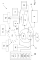
- Fig. 1 shows an embodiment of an air situation information and traffic management system 1 for aircraft according to the invention in an exemplary embodiment with necessary and useful optional components for the invention.
- ATM sensors 2 of the air situation information and traffic management system 1 are used to collect position data from (typically manned) aircraft that can be detected by ATM sensors 2.
- ATM sensors 2 air traffic management sensors
- ATM sensors 2 are stationary sensors that detect and locate aircraft in the airspace and are operated, for example, by air traffic control.
- ATM sensors 2 can, in particular, be radar sensors.
- the ATM sensors 2 are connected to a data network 3 (in particular to an air traffic control system or another central evaluation unit) and enter the position data they determine into the data network 3.
- a tracking device 4 is provided in the data network 3 and is configured to track the detected position data and process it as an air situation image 5, so that the air situation image 5 can be displayed on a display device connectable to the data network.
- the position data supplied by the ATM sensors are tracked (tracked) and displayed in the air situation image 5.
- the air situation image 5 determined from the data of the ATM sensors 2 provides, for example, air traffic control or a controller with a Overview of the airspace, especially that of manned aircraft. This is common practice within the framework of air traffic control by air traffic control authorities.
- these aircraft are equipped with portable position sensor devices 10, 11, 12 of the air situation information and traffic management system 1.
- the portable position sensor devices 10, 11, 12 are configured to record current position data. Possible embodiments of these position sensor devices proposed according to the invention can be designed as so-called hook-in devices 10, hook-on devices 11, or carry-on devices 12.
- the position sensor devices 10, 11, 12 proposed according to the invention have a radio communication device configured to communicate with a ground station 14 connected to the data network 3 via a radio network 13, preferably designed as a mobile radio network, and to input the position data of the position sensor devices 10, 11, 12 into the data network 3.
- the tracking device 4 of the air situation information and traffic management system 1 is configured to also track the position data of the portable position sensor devices 10, 11, 12 and to process them as an air situation image 5, so that the air situation image can be displayed on a display device 6 connectable to the data network.
- the tracking device 4 can particularly preferably be configured to combine the position data of the ATM sensors 2 and the position data of the portable position sensor devices 10, 11, 12 and to create a common air situation image 5 (e.g. dynamically, i.e. updated with new position data entered into the data network 3) for aircraft that can be detected by ATM sensors 2 and those that cannot be detected by ATM sensors 2 (in particular manned aircraft and non-manned aircraft whose position data is detected by the position sensor devices 10, 11, 12).
- unmanned aircraft or flying objects are equipped with either a so-called hook-on device as the position sensor device 10 or a so-called hook-in device as the position sensor device 10.
- the unmanned aircraft can, in particular, be drones 15.
- the term "drone” is also used below as a synonym for unmanned and/or non-ATM-detected aircraft.
- position sensor devices 10, 11 carried or integrated by the drone 15 are used for data exchange between the drone 15 and a traffic management system for unmanned aerial vehicles (UTM) on the ground.
- UDM unmanned aerial vehicles
- a hook-on device 10 operates independently of the drone's 15 electronics and has no connection to its flight control system. It uses a GNSS (Global Navigation Satellite System) receiver as a position sensor, its own power supply, and establishes a completely autonomous radio connection with the ground station. It transmits the data generated and recorded during the flight, in particular the position data from the GNSS receiver, to the ground station 14 via mobile radio frequencies, i.e., the mobile radio network 13. Data can also be transmitted to other drones 15 via mobile radio. Position data acquisition is not performed using radar, as is the case in manned aviation, but rather via the mobile radio network 13 and with the aid of GNSS data from the position sensor devices 10, 11, and 12.
- GNSS Global Navigation Satellite System
- the device is integrated into the electronics of the drone 15 and connected to its flight control and power supply.
- a carry-on device 12 can be included for the air situation information and traffic management system 1 described in the invention.
- a carry-on device is a mobile terminal (e.g., a smartphone, tablet, or the like) with a software application (application or app) that acts as a client for the UTM system and provides position data after login, identification, and activation. This can also be done via the mobile network 13.
- This carry-on device 12 is carried, for example, by an aircraft pilot 16 who is controlling an aircraft that cannot be detected by ATM sensors 12, e.g., according to visual flight rules.
- VFR Vehicle Flight Rules
- the position data is sent from the pilot's smartphone via the mobile network 13 using the app and to the ground station 14 and the tracking device 4.
- the GNSS signals determined by the smartphone are then calculated to form an air situation image 5 with other aircraft, both those detectable by ATM sensors 2 and those not detectable by ATM sensors 2.
- a display server 17 (which can be part of the UTM system) in the data network 3
- the air situation image 5 can be displayed, for example, on internet-based (mobile or stationary) display clients that connect to the display server 17.
- Such display clients can be, for example, the app of the tablet or smartphone as the mobile terminal 18 of the aircraft pilot 16 and transmit the air situation image 5.
- a remote pilot of a drone 15 can receive this air situation picture 5 on a suitable terminal 19 as a display device, which may, for example, be a This can be a remote control device for the drone 15 or a smartphone or tablet equipped with a suitable app.
- the aircraft pilot 16 e.g., a VFR pilot responsible for the last-minute maneuver, can avoid possible collisions using the air situation image 5 on his mobile device 18.
- the air situation information and traffic management system 1 described in the invention extends the classic tracking of manned aircraft in controlled airspace to the tracking and display of unmanned aircraft, such as drones 15, which are typically characterized by greater agility and lower movement inertia compared to manned aircraft.
- the classic methods using radar data acquisition by ATM sensors 2 are not suitable for integrating agile aircraft, such as drones 15 in particular, with rapid changes of direction.
- low-flying unmanned or manned aircraft cannot be detected by the radar.
- unmanned flying objects without additional transmitters are not detected.
- the integration of the data is achieved by the air situation information and traffic management system proposed by the invention.
- the detection of drones 15 and similar unmanned aircraft and their integration into an air situation picture 5 the known method of an Interacting Multiple Model Kalman Filter (IMM) was expanded with the present invention to create an air situation information and traffic management system 1 for manned and unmanned aircraft, which can accordingly also be referred to as a "Drone and Aircraft Surveillance Tracking System", DASTS.
- the hook-on devices 10 and hook-in devices 11 carried by unmanned aircraft, as well as the carry-on devices 12 in manned aircraft that cannot be detected by ATM sensors 2 for other reasons, are part of the system as position sensor devices 10, 11, 12 for collecting position data.
- position sensor devices 10, 11, 12 are connected to the air traffic control data network 3 via the mobile network 13 of a telecommunications provider or dial into it to address connected, network-capable components.
- Data acquired by the position sensor devices 10, 11, 12, in particular the position data or other surveillance data, are thus input into the data network 3, where they are forwarded to the tracking device 4.
- the tracking device 4 uses the transmitted position data 20 of the flying objects, compensates for measurement errors, timing errors, temporal bulking (temporal stretching or making them more voluminous), or gaps using the IMM filter (explanation follows later), and then calculates a track position to generate an air situation picture 5, which can also be referred to as situational awareness. This creates a calculated movement, consisting of target course and ground speed, from the data plots of the position sensor devices 10, 11, 12.
- the position data 20 of the ATM sensors 2 and the position sensor devices 10, 11, 12 are represented according to the invention as plots in which the temporal sequence of the position data 20 is shown in order to extract the flight path 21 (track) of the aircraft therefrom.
- the tracking device 4 has an extended Interacting Multiple Model Kalman Filter (IMM), which uses different motion models, turning flight, straight flight, standstill, and especially motion data of higher dynamics - possibly depending on the data channel - to model the movements of unmanned aerial vehicles.
- IMM Interacting Multiple Model Kalman Filter
- the tracking device 4 takes into account, in particular, the higher agility of drones 15 or unmanned aerial vehicles in general, and can assign appropriately adjusted safety distances, which are determined from expectation windows 22, 23.
- expectation windows 22, 23 For example, for typically slower manned aerial vehicles, such as aircraft 24, longitudinally distorted ellipsoids are used as expectation windows 23 in the calculation (cf. Fig. 3 ).
- circular ellipsoids are used as expectation windows 22.
- the air situation information and traffic management system evaluates the flight paths 21 (tracks) of the individual aircraft by pairwise comparison using the expectation windows 22, 23 in circles and ellipses around the aircraft 15, 24 to indicate potential conflicts and provide suggestions for track guidance.
- the air situation information and traffic management system When comparing the tracks of the flying objects in pairs, the air situation information and traffic management system performs an "octal tree" sorting around the respective track position.
- the comparison of all track positions takes into account all incoming data from the flying objects, i.e., in addition to the radar data, in particular the kinematic data of the unmanned flying objects from the position sensor devices 10, 11, 12, such as speed, GNSS position, acceleration, course, and variances.
- the air situation information and traffic management system uses this data to determine an expectation window 22, 23 for future movement to enable risk assessment.
- head symbols 25 for the tracks 21 indicate the current flight position.
- a future vector 26 shows the direction and speed.
- the past flight tracks of the flight path 21 are described in an air situation image 5 with so-called history dots 27, thus indicating the past flight path.
- the unmanned aircraft shown are labeled 28 on the air situation image 5, which contain geometric and barometric altitude information.
- the head symbol 25 of the unmanned aerial vehicle's track can also receive data from other sensors of the unmanned aerial vehicle. This can include, for example, the battery charge level, control status, or telemetry data. Maintenance engineers can view information on the measurement and tracking quality on an additional analysis display.
- the operator also receives information and warnings about possible collisions in an air situation picture 5, shown here as an example.
- the air situation information and traffic management system displays such an air situation picture 5 with risk assessment and alarm functionality for all aircraft or flying objects in the airspace for the pilot, for example, of an unmanned drone 5. This information is also available to operators, if necessary, employees of law enforcement and security authorities, and if necessary, air traffic controllers.
- the air situation images 5 can be prepared differently depending on the respective user and can differ in their presentation.
- the aggregated data can be displayed on the display device 6, 18, 19 against the background of selectable maps.
- DDS drone detection systems 30
- an air traffic controller at an airport control tower for example, can be presented with additional information about the activities of unmanned aircraft or flying objects (such as drones 15) in the immediate vicinity of airports in various critical areas depending on the degree of danger.
- critical infrastructures, test tracks, industrial facilities, correctional facilities, etc. can be monitored with regard to the overflight of unmanned flying objects.
- the resulting air situation image 31 for drone detection then shows, for example, spatial-temporal conflicts with such defined static, dynamic, and temporary geo-fences and geo-cages (geo-area). This is possible because the air situation information and traffic management system uses data fusion with Covariance intersection allows the assessment of the cooperativity of unmanned aerial vehicles (such as drones 15).
- the air situation information and traffic management system for drones 15 with a hook-in device 11 can enable direct intervention in the flight control of a drone 15 or an unmanned aerial vehicle via a control signal that can be transmitted via a separate data channel. This is also possible through direct communication with a radio remote control of the drone 15 on the ground, whereby control of the drone 15 is taken over or intervened in.
- control can be handed over from the pilot of the unmanned aerial vehicle to the air situation information and traffic management system, for example, automatically taking over control or changing the flight route segment.
- the air situation information and traffic management system presented in the invention generally provides information on obstacles, no-fly zones, weather conditions, and other authorized flight missions for mission planning of unmanned aerial vehicles. This allows the operator or pilot to determine flight prioritization and/or plan control interventions in the unmanned aircraft's mission based on more precise information, or even (in the future) to automate these actions.
Landscapes
- Engineering & Computer Science (AREA)
- Physics & Mathematics (AREA)
- Radar, Positioning & Navigation (AREA)
- Remote Sensing (AREA)
- General Physics & Mathematics (AREA)
- Aviation & Aerospace Engineering (AREA)
- Computer Networks & Wireless Communication (AREA)
- Electromagnetism (AREA)
- Traffic Control Systems (AREA)
Claims (14)
- Système d'information sur la position aérienne et de gestion du trafic pour les aéronefs avec ou sans pilote, dans lequel les données de position des aéronefs détectables par les capteurs ATM (2) sont détectées, suivies et représentées dans une image de position aérienne (5) au moyen des capteurs ATM (2) du système d'information sur la position aérienne et de gestion du trafic (1),• dans lequel les capteurs ATM (2) sont connectés à un réseau de données (3) fourni par un système de contrôle du trafic aérien et téléchargent les données de position (20) de l'aéronef reconnu dans le réseau de données (3) et• dans lequel le réseau de données (3) comprend un dispositif de suivi (4) configuré pour suivre les données de position reconnues (20) et les préparer en tant qu'image de position aérienne (5), de sorte que l'image de position aérienne (5) puisse être représentée sur un dispositif d'affichage (6, 18, 19) pouvant être connecté au réseau de données (3),• dans lequel les aéronefs qui ne sont pas détectables au moyen des capteurs ATM (2) sont équipés d'un dispositif de capteur de position portable (10, 11, 12) du système d'information sur la position aérienne et de gestion du trafic (1), le dispositif de capteur de position portable (10, 11, 12) étant configuré pour détecter les données de position actuelle (20),• dans lequel le dispositif de suivi (4) est configuré pour suivre les données de position des dispositifs de capteurs de position portables (10, 11, 12) et pour les préparer en tant qu'image de position aérienne (5), de sorte que l'image de position aérienne (5) puisse être représentée sur un dispositif d'affichage (5) pouvant être connecté au réseau de données (3),dans lequel• les capteurs ATM (2) sont des capteurs stationnaires qui ne sont pas embarqués à bord de l'aéronef et qui reconnaissent et localisent les aéronefs dans l'espace aérien,• le dispositif de capteur de position (10, 11, 12) possède un dispositif de communication radio configuré pour communiquer avec une station au sol (14) connectée au réseau de données (3) et pour télécharger les données de position (20) dans le réseau de données (3), ledit dispositif de communication radio étant un dispositif de communication radio mobile configuré pour communiquer, via un réseau radio (13) conçu comme un réseau de communication radio mobile, avec la station au sol (14) qui est connectée au réseau de données (3) et pour télécharger les données de position (2) des dispositifs de détection de position (10, 11, 12) dans le réseau de données (3),dans lequel le dispositif de suivi (4) est configuré pour combiner les données de position (20) des capteurs ATM (2) et les données de position (20) des dispositifs de capteurs de position portables (10, 11, 12), et pour créer une image de position aérienne partagée (5) pour les aéronefs qui sont détectables par les capteurs ATM (2) et les aéronefs qui ne sont pas détectables par les capteurs ATM (2), dans laquelle, dans ladite image de position aérienne (5), les données de position des capteurs ATM (2) et des dispositifs de capteurs de position (10, 11, 12) sont représentées sous forme de tracés représentant la séquence temporelle des données de position (20), afin d'en extraire la trajectoire de vol de l'aéronef, caractérisé en ce queledit dispositif de suivi (4) comprend un filtre de Kalman amélioré à modèles multiples en interaction qui utilise différents modèles de mouvement, le vol en virage, le vol en ligne droite, l'arrêt et des données de mouvement à dynamique plus élevée pour modéliser les mouvements des objets volants sans pilote et ledit dispositif de suivi (4) est configuré pour prendre en compte la plus grande agilité des drones et des objets volants sans pilote en général dans une évaluation statistique des risques et attribue des distances de sécurité qui sont déterminées à partir des fenêtres d'attente (22, 23), etce que le dispositif de suivi (4) est configuré pour utiliser des ellipsoïdes avec une distorsion longitudinale le long de la direction de mouvement pour les fenêtres d'attente (23) des aéronefs en tant qu'objets volants pilotés inertes (14), et pour utiliser des ellipsoïdes circulaires pour les fenêtres d'attente (22) des drones en tant qu'objets volants non pilotés agiles (15).
- Système d'information sur la position aérienne et de gestion du trafic selon la revendication 1, caractérisé en ce qu'une image de position aérienne (5) peut être représentée sur un dispositif d'affichage (6, 18, 19), le dispositif d'affichage accédant au réseau de données (3).
- Système d'information sur la position aérienne et de gestion du trafic selon la revendication 2, caractérisé en ce que le dispositif d'affichage (6, 18, 19) est intégré au réseau de données (3), ou est connecté au réseau de données (3) en accédant à un serveur de présentation (17), intégré au réseau de données (3) en tant que client de présentation.
- Système d'information sur les positions aériennes et de gestion du trafic selon l'une quelconque des revendications précédentes, caractérisé en ce qu'un ou plusieurs des éléments d'information suivants peuvent être représentés dans l'image de position aérienne (5) :• des positions dotées d'informations de position concernant les opérations des aéronefs pilotés et/ou non pilotés ;• les trajectoires de vol mises à jour dynamiquement et dotées d'étiquettes (28), dans lesquelles les points et/ou les lignes en pointillé (27) des trajectoires de vol représentent la trajectoire de vol passée, un symbole en forme de flèche (28) représente la position de vol actuelle et une ligne continue en tant que vecteur futur (26) représente la direction et la vitesse actuelles ;• les conflits spatio-temporels avec des géorégions statiques, dynamiques et temporaires qui sont déterminés sur la base de l'image de position aérienne créée ;• les conflits spatio-temporels entre les aéronefs sans pilote ainsi qu'entre les aéronefs avec pilote et les aéronefs sans pilote qui sont déterminés sur la base de l'image de position aérienne créée ;• une carte d'arrière-plan librement sélectionnable ;• les positions de contrôle avec les informations de position concernant les opérations des objets volants non habités.
- Système d'information sur la position aérienne et de gestion du trafic selon l'une quelconque des revendications précédentes, caractérisé en ce que les données de position (20) téléchargées dans le réseau de données (3) comprennent d'autres données de surveillance concernant le type et/ou le statut de l'aéronef.
- Système d'information sur la position aérienne et de gestion du trafic selon l'une quelconque des revendications précédentes, caractérisé en ce que les aéronefs qui ne sont pas détectables au moyen des capteurs ATM (2) sont des aéronefs non habités dans lesquels aucun pilote n'est à bord, ou des aéronefs habités dans des espaces aériens inférieurs qui sont contrôlés par un pilote mais qui ne sont pas détectables par les capteurs ATM (2) de manière systématique.
- Système d'information sur la position aérienne et de gestion du trafic selon l'une quelconque des revendications précédentes, caractérisé en ce qu'au moins une partie des aéronefs qui ne sont pas détectables au moyen des capteurs ATM (2) comprennent, en tant que dispositif de capteur de position (10), un dispositif fonctionnant de manière autonome avec sa propre alimentation en énergie, qui forme avec l'aéronef une unité structurelle mais n'est pas en liaison de communication avec l'aéronef.
- Système d'information sur la position aérienne et de gestion du trafic selon l'une quelconque des revendications précédentes, caractérisé en ce qu'au moins une partie de l'aéronef qui n'est pas détectable au moyen des capteurs ATM (2) comprend, en tant que dispositif de capteur de position (12), un dispositif fonctionnant de manière autonome avec sa propre alimentation électrique, et qui, en tant qu'application intégrée dans un terminal mobile avec un processeur et une unité de communication, peut être exécuté sur le terminal mobile.
- Système d'information sur la position aérienne et de gestion du trafic selon l'une quelconque des revendications précédentes, caractérisé en ce qu'au moins une partie de l'aéronef qui n'est pas détectable au moyen des capteurs ATM (2) comprend, en tant que dispositif capteur de position (11), un dispositif pouvant être connecté électriquement et/ou électroniquement au système électrique de bord de l'aéronef, et pouvant être connecté au système électronique de commande et/ou à l'alimentation électrique de celui-ci.
- Système d'information sur la position aérienne et de gestion du trafic selon l'une quelconque des revendications précédentes, caractérisé en ce que le dispositif de radiocommunication est un dispositif de radiocommunication mobile ou par satellite.
- Système d'information sur la position de l'air et de gestion du trafic selon l'une quelconque des revendications précédentes, caractérisé en ce que le dispositif de communication radio permet une communication bidirectionnelle, avec une communication aller du dispositif de mesure de la position (10, 11, 12) vers le réseau de données (3), et une communication retour du réseau de données (3) vers le dispositif de détection de la position (10, 11, 12).
- Système d'information sur la position aérienne et de gestion du trafic selon la revendication 11, caractérisé en ce que dans une communication inverse du réseau de données (3) vers les dispositifs de mesure de la position (10, 11, 12), une intervention dans la commande de vol est également prévue.
- Système d'information sur la position aérienne et de gestion du trafic selon l'une quelconque des revendications précédentes, caractérisé en ce que le dispositif de capteur de position (10, 11, 12) détermine les données de position (20) par l'intermédiaire d'un système mondial de navigation par satellite.
- Système d'information sur la position aérienne et de gestion du trafic selon l'une quelconque des revendications précédentes, caractérisé en ce que le dispositif de capteur de position (10, 11, 12) détermine les données de position (20) à partir des données de capteurs qui sont connectés au système électrique de bord de l'aéronef.
Applications Claiming Priority (2)
| Application Number | Priority Date | Filing Date | Title |
|---|---|---|---|
| DE102018105045.3A DE102018105045A1 (de) | 2018-03-06 | 2018-03-06 | Luftlageinformations- und Verkehrsmanagementsystem für unbemannte und bemannte Luftfahrzeuge |
| PCT/EP2019/055407 WO2019170649A1 (fr) | 2018-03-06 | 2019-03-05 | Système de gestion d'informations de situation aérienne et de trafic pour véhicules aériens sans pilote et pilotés |
Publications (3)
| Publication Number | Publication Date |
|---|---|
| EP3762913A1 EP3762913A1 (fr) | 2021-01-13 |
| EP3762913C0 EP3762913C0 (fr) | 2025-04-30 |
| EP3762913B1 true EP3762913B1 (fr) | 2025-04-30 |
Family
ID=65686865
Family Applications (1)
| Application Number | Title | Priority Date | Filing Date |
|---|---|---|---|
| EP19709449.3A Active EP3762913B1 (fr) | 2018-03-06 | 2019-03-05 | Système de gestion d'informations de situation aérienne et de trafic pour véhicules aériens sans pilote et pilotés |
Country Status (5)
| Country | Link |
|---|---|
| US (1) | US12131651B2 (fr) |
| EP (1) | EP3762913B1 (fr) |
| CN (1) | CN111819610A (fr) |
| DE (1) | DE102018105045A1 (fr) |
| WO (1) | WO2019170649A1 (fr) |
Families Citing this family (12)
| Publication number | Priority date | Publication date | Assignee | Title |
|---|---|---|---|---|
| US11410559B2 (en) * | 2018-07-05 | 2022-08-09 | Ge Aviation Systems Llc | Intelligent unmanned aerial vehicle traffic management via an infrastructure network |
| WO2021198729A1 (fr) * | 2020-03-31 | 2021-10-07 | Telefonaktiebolaget Lm Ericsson (Publ) | Estimation d'état de drone par une seule station de base |
| US12399274B2 (en) | 2020-07-10 | 2025-08-26 | Skystream LLC | Enhanced LDACS that uses doppler shifts in carrier signals for positioning and navigation |
| US11909501B2 (en) | 2020-07-10 | 2024-02-20 | Skystream LLC | Enhanced LDACS system having roaming agreements and associated methods |
| US11495132B2 (en) * | 2020-09-08 | 2022-11-08 | Ge Aviation Systems Llc | UTM-ATC interface |
| CN112466103B (zh) | 2020-11-12 | 2021-10-01 | 北京航空航天大学 | 航空器飞行威胁演化预警方法、装置、设备及存储介质 |
| EP4036599B1 (fr) * | 2021-01-27 | 2025-07-23 | Infineon Technologies AG | Interaction d'algorithme de suivi multi-modèles interactif utilisant le modèle d'état de repos |
| CN114371446B (zh) * | 2021-12-22 | 2026-02-27 | 中国电子科技集团公司第十四研究所 | 一种雷达组合态势分析方法 |
| CN115675918A (zh) * | 2022-10-21 | 2023-02-03 | 北京开运联合信息技术集团股份有限公司 | 一种导航卫星空间态势感知系统 |
| AT527720A1 (de) * | 2023-10-20 | 2025-05-15 | Frequentis Ag | Flugleitsystem |
| CN118191844B (zh) * | 2024-05-17 | 2024-07-19 | 中国民航科学技术研究院 | 一种低空空域无人机运行的动态风险态势感知方法 |
| CN121366503B (zh) * | 2025-12-23 | 2026-04-03 | 成都航空职业技术大学 | 一种基于ads-b的无人机与有人机融合空域监视方法 |
Family Cites Families (12)
| Publication number | Priority date | Publication date | Assignee | Title |
|---|---|---|---|---|
| DE19826737A1 (de) * | 1998-06-16 | 1999-12-23 | Jens Rainer Schuessler | Verfahren und System zum Warnen vor Kollisionen zwischen Fluggeräten |
| FR2810146A1 (fr) | 2000-06-09 | 2001-12-14 | Thomson Csf | Procede d'elaboration d'une trajectoire d'evitement dans le plan horizontal pour aeronef en vue de la resolution d'un conflit de trafic |
| US7269513B2 (en) * | 2005-05-03 | 2007-09-11 | Herwitz Stanley R | Ground-based sense-and-avoid display system (SAVDS) for unmanned aerial vehicles |
| US8358677B2 (en) * | 2008-06-24 | 2013-01-22 | Honeywell International Inc. | Virtual or remote transponder |
| EP2458399A1 (fr) * | 2010-11-26 | 2012-05-30 | Siemens IT Solutions and Services GmbH | Procédé de détection et de sortie de la position actuelle d'un objet |
| US8792905B1 (en) | 2012-03-01 | 2014-07-29 | Google Inc. | Location monitoring using clusters of entities |
| US10302759B1 (en) * | 2013-03-05 | 2019-05-28 | The United States Of America As Represented By The Administrator Of The National Aeronautics And Space Administration | Automatic dependent surveillance broadcast (ADS-B) system with radar for ownship and traffic situational awareness |
| CN203773355U (zh) * | 2013-12-05 | 2014-08-13 | 梁谋强 | 三维立体多图层式无人机实时定位监管装置 |
| US9473367B2 (en) * | 2014-08-19 | 2016-10-18 | Honeywell International Inc. | Aircraft monitoring with improved situational awareness |
| US10185316B2 (en) | 2015-08-10 | 2019-01-22 | Edward Kablaoui | System and method for drone connectivity and communication over a cellular network |
| DE102015116117B4 (de) * | 2015-09-23 | 2018-10-31 | Intel Deutschland Gmbh | Verfahren und System zum Bereitstellen einer Luftdarstellung |
| CN107274724B (zh) * | 2017-07-25 | 2020-06-02 | 中国航空器拥有者及驾驶员协会 | 一种基于自组网络中继与gsm通信的无人机监控系统 |
-
2018
- 2018-03-06 DE DE102018105045.3A patent/DE102018105045A1/de active Pending
-
2019
- 2019-03-05 WO PCT/EP2019/055407 patent/WO2019170649A1/fr not_active Ceased
- 2019-03-05 EP EP19709449.3A patent/EP3762913B1/fr active Active
- 2019-03-05 CN CN201980017103.XA patent/CN111819610A/zh active Pending
- 2019-03-05 US US16/978,353 patent/US12131651B2/en active Active
Non-Patent Citations (2)
| Title |
|---|
| CHO TAEHWAN: "Automatic Dependent Surveillance - Broadcast for surveillance of Unmanned Aircraft System", 2017 INTEGRATED COMMUNICATIONS, NAVIGATION AND SURVEILLANCE CONFERENCE (ICNS), IEEE, 18 April 2017 (2017-04-18), XP033143166, DOI: 10.1109/ICNSURV.2017.8011925 * |
| RAMASAMY SUBRAMANIAN ET AL: "A unified approach to cooperative and non-cooperative Sense-and-Avoid", 2015 INTERNATIONAL CONFERENCE ON UNMANNED AIRCRAFT SYSTEMS (ICUAS), IEEE, 9 June 2015 (2015-06-09), pages 765 - 773, XP033171579, DOI: 10.1109/ICUAS.2015.7152360 * |
Also Published As
| Publication number | Publication date |
|---|---|
| US20210043094A1 (en) | 2021-02-11 |
| EP3762913A1 (fr) | 2021-01-13 |
| EP3762913C0 (fr) | 2025-04-30 |
| DE102018105045A1 (de) | 2019-09-12 |
| WO2019170649A1 (fr) | 2019-09-12 |
| US12131651B2 (en) | 2024-10-29 |
| CN111819610A (zh) | 2020-10-23 |
Similar Documents
| Publication | Publication Date | Title |
|---|---|---|
| EP3762913B1 (fr) | Système de gestion d'informations de situation aérienne et de trafic pour véhicules aériens sans pilote et pilotés | |
| DE602004007133T2 (de) | Integriertes system zum ausweichen vor hindernissen während des freien fluges | |
| EP3129971B1 (fr) | Procédé de surveillance d'espace aérien | |
| US8368584B2 (en) | Airspace risk mitigation system | |
| CN103592948B (zh) | 无人机飞行防撞方法 | |
| US11790792B2 (en) | UTM-ATC interface | |
| WO2018195573A1 (fr) | Aéronef sans pilote équipé d'une unité de commande modulaire de vol en formation | |
| DE102012018637A1 (de) | Vorrichtung zur Warnung vor aerologischen Phänomenen für ein Flugzeug | |
| EP3648081A1 (fr) | Procédé de fonctionnement d'un aéronef au moins temporairement sans pilote ainsi qu'un tel aéronef | |
| DE212015000274U1 (de) | Vorrichtung und nichtflüchtiges Computerprogrammprodukt zur Überwachung einer Flugzeugposition | |
| DE69903169T2 (de) | Vorrichtung bestimmt zur verbesserung der sicherheit von flugzeugen während des sichtfluges | |
| EP1109032B1 (fr) | Procédé et dispositif d'avertissement des collisions entre avions | |
| DE10120537A1 (de) | Verfahren mit einem interferometrischen ROSAR-Gerät | |
| Kern et al. | City-ATM—Demonstration of Traffic Management in Urban Airspace in case of bridge inspection | |
| DE102008026415A1 (de) | System zur Überwachung von Bewegungen von Flugkörpern im Luftraum | |
| Kephart et al. | See-and-avoid comparison of performance in manned and remotely piloted aircraft | |
| Mcswain | High density vertiplex flight test report advanced onboard automation | |
| Capello et al. | Regulation analysis and new concept for a cloud-based UAV supervision system in urban environment | |
| Le Tallec et al. | Low level rpas traffic management (llrtm) concept of operation | |
| TWM609087U (zh) | 無人機飛航管理系統 | |
| Mutuel et al. | Functional decomposition of Unmanned Aircraft Systems (UAS) for CNS capabilities in NAS integration | |
| RU2852794C1 (ru) | Интегрированная система мониторинга, управления и информационного обеспечения движения воздушных, наземных и надводных беспилотных систем | |
| Spaulding | Reaching Beyond: Testing and Evaluation of Onboard DAA System for Small Unmanned Aircraft BVOLS Operations | |
| RU2376203C2 (ru) | Комплекс взлета, пилотирования и посадки автоматизированных воздушных судов | |
| Marshall | Coordination with Manned Aircraft and Air Traffic Control |
Legal Events
| Date | Code | Title | Description |
|---|---|---|---|
| STAA | Information on the status of an ep patent application or granted ep patent |
Free format text: STATUS: UNKNOWN |
|
| STAA | Information on the status of an ep patent application or granted ep patent |
Free format text: STATUS: THE INTERNATIONAL PUBLICATION HAS BEEN MADE |
|
| PUAI | Public reference made under article 153(3) epc to a published international application that has entered the european phase |
Free format text: ORIGINAL CODE: 0009012 |
|
| STAA | Information on the status of an ep patent application or granted ep patent |
Free format text: STATUS: REQUEST FOR EXAMINATION WAS MADE |
|
| 17P | Request for examination filed |
Effective date: 20200907 |
|
| AK | Designated contracting states |
Kind code of ref document: A1 Designated state(s): AL AT BE BG CH CY CZ DE DK EE ES FI FR GB GR HR HU IE IS IT LI LT LU LV MC MK MT NL NO PL PT RO RS SE SI SK SM TR |
|
| AX | Request for extension of the european patent |
Extension state: BA ME |
|
| DAV | Request for validation of the european patent (deleted) | ||
| DAX | Request for extension of the european patent (deleted) | ||
| STAA | Information on the status of an ep patent application or granted ep patent |
Free format text: STATUS: EXAMINATION IS IN PROGRESS |
|
| 17Q | First examination report despatched |
Effective date: 20230426 |
|
| GRAP | Despatch of communication of intention to grant a patent |
Free format text: ORIGINAL CODE: EPIDOSNIGR1 |
|
| STAA | Information on the status of an ep patent application or granted ep patent |
Free format text: STATUS: GRANT OF PATENT IS INTENDED |
|
| RIC1 | Information provided on ipc code assigned before grant |
Ipc: G01S 13/933 20200101ALI20241016BHEP Ipc: G01S 13/91 20060101ALI20241016BHEP Ipc: G01S 13/93 20200101ALI20241016BHEP Ipc: G01S 5/00 20060101ALI20241016BHEP Ipc: G08G 5/00 20060101AFI20241016BHEP |
|
| INTG | Intention to grant announced |
Effective date: 20241112 |
|
| GRAS | Grant fee paid |
Free format text: ORIGINAL CODE: EPIDOSNIGR3 |
|
| GRAA | (expected) grant |
Free format text: ORIGINAL CODE: 0009210 |
|
| STAA | Information on the status of an ep patent application or granted ep patent |
Free format text: STATUS: THE PATENT HAS BEEN GRANTED |
|
| AK | Designated contracting states |
Kind code of ref document: B1 Designated state(s): AL AT BE BG CH CY CZ DE DK EE ES FI FR GB GR HR HU IE IS IT LI LT LU LV MC MK MT NL NO PL PT RO RS SE SI SK SM TR |
|
| REG | Reference to a national code |
Ref country code: CH Ref legal event code: EP Ref country code: GB Ref legal event code: FG4D Free format text: NOT ENGLISH |
|
| REG | Reference to a national code |
Ref country code: IE Ref legal event code: FG4D Free format text: LANGUAGE OF EP DOCUMENT: GERMAN |
|
| REG | Reference to a national code |
Ref country code: DE Ref legal event code: R096 Ref document number: 502019013285 Country of ref document: DE |
|
| U01 | Request for unitary effect filed |
Effective date: 20250526 |
|
| U07 | Unitary effect registered |
Designated state(s): AT BE BG DE DK EE FI FR IT LT LU LV MT NL PT RO SE SI Effective date: 20250603 |
|
| PG25 | Lapsed in a contracting state [announced via postgrant information from national office to epo] |
Ref country code: ES Free format text: LAPSE BECAUSE OF FAILURE TO SUBMIT A TRANSLATION OF THE DESCRIPTION OR TO PAY THE FEE WITHIN THE PRESCRIBED TIME-LIMIT Effective date: 20250430 |
|
| PG25 | Lapsed in a contracting state [announced via postgrant information from national office to epo] |
Ref country code: NO Free format text: LAPSE BECAUSE OF FAILURE TO SUBMIT A TRANSLATION OF THE DESCRIPTION OR TO PAY THE FEE WITHIN THE PRESCRIBED TIME-LIMIT Effective date: 20250730 Ref country code: GR Free format text: LAPSE BECAUSE OF FAILURE TO SUBMIT A TRANSLATION OF THE DESCRIPTION OR TO PAY THE FEE WITHIN THE PRESCRIBED TIME-LIMIT Effective date: 20250731 |
|
| PG25 | Lapsed in a contracting state [announced via postgrant information from national office to epo] |
Ref country code: PL Free format text: LAPSE BECAUSE OF FAILURE TO SUBMIT A TRANSLATION OF THE DESCRIPTION OR TO PAY THE FEE WITHIN THE PRESCRIBED TIME-LIMIT Effective date: 20250430 |
|
| PG25 | Lapsed in a contracting state [announced via postgrant information from national office to epo] |
Ref country code: HR Free format text: LAPSE BECAUSE OF FAILURE TO SUBMIT A TRANSLATION OF THE DESCRIPTION OR TO PAY THE FEE WITHIN THE PRESCRIBED TIME-LIMIT Effective date: 20250430 |
|
| PG25 | Lapsed in a contracting state [announced via postgrant information from national office to epo] |
Ref country code: RS Free format text: LAPSE BECAUSE OF FAILURE TO SUBMIT A TRANSLATION OF THE DESCRIPTION OR TO PAY THE FEE WITHIN THE PRESCRIBED TIME-LIMIT Effective date: 20250731 |
|
| PG25 | Lapsed in a contracting state [announced via postgrant information from national office to epo] |
Ref country code: IS Free format text: LAPSE BECAUSE OF FAILURE TO SUBMIT A TRANSLATION OF THE DESCRIPTION OR TO PAY THE FEE WITHIN THE PRESCRIBED TIME-LIMIT Effective date: 20250830 |
|
| PG25 | Lapsed in a contracting state [announced via postgrant information from national office to epo] |
Ref country code: SM Free format text: LAPSE BECAUSE OF FAILURE TO SUBMIT A TRANSLATION OF THE DESCRIPTION OR TO PAY THE FEE WITHIN THE PRESCRIBED TIME-LIMIT Effective date: 20250430 |
|
| PG25 | Lapsed in a contracting state [announced via postgrant information from national office to epo] |
Ref country code: CZ Free format text: LAPSE BECAUSE OF FAILURE TO SUBMIT A TRANSLATION OF THE DESCRIPTION OR TO PAY THE FEE WITHIN THE PRESCRIBED TIME-LIMIT Effective date: 20250430 |
|
| PG25 | Lapsed in a contracting state [announced via postgrant information from national office to epo] |
Ref country code: SK Free format text: LAPSE BECAUSE OF FAILURE TO SUBMIT A TRANSLATION OF THE DESCRIPTION OR TO PAY THE FEE WITHIN THE PRESCRIBED TIME-LIMIT Effective date: 20250430 |
|
| PLBE | No opposition filed within time limit |
Free format text: ORIGINAL CODE: 0009261 |
|
| STAA | Information on the status of an ep patent application or granted ep patent |
Free format text: STATUS: NO OPPOSITION FILED WITHIN TIME LIMIT |
|
| REG | Reference to a national code |
Ref country code: CH Ref legal event code: L10 Free format text: ST27 STATUS EVENT CODE: U-0-0-L10-L00 (AS PROVIDED BY THE NATIONAL OFFICE) Effective date: 20260311 |
|
| 26N | No opposition filed |
Effective date: 20260202 |
|
| U20 | Renewal fee for the european patent with unitary effect paid |
Year of fee payment: 8 Effective date: 20260324 |