EP3762954B1 - Bouton-poussoir ayant un anneau d'éclairage - Google Patents
Bouton-poussoir ayant un anneau d'éclairage Download PDFInfo
- Publication number
- EP3762954B1 EP3762954B1 EP19731062.6A EP19731062A EP3762954B1 EP 3762954 B1 EP3762954 B1 EP 3762954B1 EP 19731062 A EP19731062 A EP 19731062A EP 3762954 B1 EP3762954 B1 EP 3762954B1
- Authority
- EP
- European Patent Office
- Prior art keywords
- light
- gap
- button
- shot
- hardware product
- Prior art date
- Legal status (The legal status is an assumption and is not a legal conclusion. Google has not performed a legal analysis and makes no representation as to the accuracy of the status listed.)
- Active
Links
Images




Classifications
-
- H—ELECTRICITY
- H01—ELECTRIC ELEMENTS
- H01H—ELECTRIC SWITCHES; RELAYS; SELECTORS; EMERGENCY PROTECTIVE DEVICES
- H01H13/00—Switches having rectilinearly-movable operating part or parts adapted for pushing or pulling in one direction only, e.g. push-button switch
- H01H13/02—Details
- H01H13/023—Light-emitting indicators
-
- F—MECHANICAL ENGINEERING; LIGHTING; HEATING; WEAPONS; BLASTING
- F21—LIGHTING
- F21V—FUNCTIONAL FEATURES OR DETAILS OF LIGHTING DEVICES OR SYSTEMS THEREOF; STRUCTURAL COMBINATIONS OF LIGHTING DEVICES WITH OTHER ARTICLES, NOT OTHERWISE PROVIDED FOR
- F21V19/00—Fastening of light sources or lamp holders
- F21V19/001—Fastening of light sources or lamp holders the light sources being semiconductors devices, e.g. LEDs
-
- F—MECHANICAL ENGINEERING; LIGHTING; HEATING; WEAPONS; BLASTING
- F21—LIGHTING
- F21V—FUNCTIONAL FEATURES OR DETAILS OF LIGHTING DEVICES OR SYSTEMS THEREOF; STRUCTURAL COMBINATIONS OF LIGHTING DEVICES WITH OTHER ARTICLES, NOT OTHERWISE PROVIDED FOR
- F21V3/00—Globes; Bowls; Cover glasses
- F21V3/04—Globes; Bowls; Cover glasses characterised by materials, surface treatments or coatings
- F21V3/06—Globes; Bowls; Cover glasses characterised by materials, surface treatments or coatings characterised by the material
- F21V3/062—Globes; Bowls; Cover glasses characterised by materials, surface treatments or coatings characterised by the material the material being plastics
- F21V3/0625—Globes; Bowls; Cover glasses characterised by materials, surface treatments or coatings characterised by the material the material being plastics the material diffusing light, e.g. translucent plastics
-
- F—MECHANICAL ENGINEERING; LIGHTING; HEATING; WEAPONS; BLASTING
- F21—LIGHTING
- F21Y—INDEXING SCHEME ASSOCIATED WITH SUBCLASSES F21K, F21L, F21S and F21V, RELATING TO THE FORM OR THE KIND OF THE LIGHT SOURCES OR OF THE COLOUR OF THE LIGHT EMITTED
- F21Y2115/00—Light-generating elements of semiconductor light sources
- F21Y2115/10—Light-emitting diodes [LED]
-
- H—ELECTRICITY
- H01—ELECTRIC ELEMENTS
- H01H—ELECTRIC SWITCHES; RELAYS; SELECTORS; EMERGENCY PROTECTIVE DEVICES
- H01H2219/00—Legends
- H01H2219/054—Optical elements
- H01H2219/062—Light conductor
- H01H2219/0622—Light conductor only an illuminated ring around keys
-
- H—ELECTRICITY
- H01—ELECTRIC ELEMENTS
- H01H—ELECTRIC SWITCHES; RELAYS; SELECTORS; EMERGENCY PROTECTIVE DEVICES
- H01H9/00—Details of switching devices, not covered by groups H01H1/00 - H01H7/00
- H01H9/18—Distinguishing marks on switches, e.g. for indicating switch location in the dark; Adaptation of switches to receive distinguishing marks
Definitions
- Hardware products frequently employ illumination to achieve user interface, industrial design, and marketing goals. Illumination can convey a message or status indication to a user using color or by varying in intensity. Products may also be differentiated from one another based on an illumination scheme.
- a button as for example disclosed in US 5,993,019 A1 , EP 2 538 427 A1 or EP 1 467 387 A1 , on a hardware product may employ illumination in the form of a "ring" of light that surrounds the perimeter of the button.
- a light ring may be implemented using multiple light-emitting diodes (LEDs) positioned to approximate the shape of a ring.
- LEDs light-emitting diodes
- Light rings may also use dedicated optical components, such as light diffusers, light pipes, and/or light guides to direct and channel the light into the desired light pattern. Because the optical components used to achieve the light ring effect occupy the limited space surrounding the button, additional complexity and costs are imposed to ensure that those components do not interfere with the function of the button.
- Dead front is a design aesthetic where a device's illuminating elements are at least partially obscured when in the off state. Providing a dead front effect for a light ring typically involves additional processing and/or light-reflecting parts, and coatings; all of which add to the cost of the final product.
- the maximum dimension of the first gap may be in a range of 0.15-0.25 mm, 0.20-0.24 mm, approximately 0.22 millimeters, or the like
- the maximum dimension of the second gap may be 0.10-0.20 mm, 0.14-0.16 mm, approximately 0.15 millimetes, or the like.
- the second gap may be disposed adjacent to the first gap in parallel with the depression axis of the button.
- the hardware product lso includes a light-emitting component electrically coupled to a printed circuit board.
- the present subject matter discloses structures and techniques to achieve a light ring effect and a dead front effect.
- the button When used with a button in one example, the button itself may be used as a light diffuser in conjunction with one or more gaps surrounding the button to achieve the light ring effect without multiple LEDs, dedicated optical parts, or additional processes.
- the disclosed subject matter may be used in conjunction with a variety of handheld, wall-mounted, and free-standing electronic devices, such as a game controller, game console, remote control, set-top box, thermostat control panel, security system control panel, dimmer/switch, audio system control panel, and the like.
- the disclosed subject matter may provide visual appeal and utility from a variety of angles and distances, and particularly in dark and semi-dark environments where the light ring effect may be more readily observed.
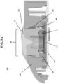
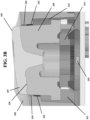
- FIG. 3A illustrates an example cross-sectional view of hardware product 200.
- button 105 is located within the opening 230 of the housing 205.
- An internal cavity 315 exists within hardware product 200 where the PCB 310 and the single light-emitting component 210 are located.
- a resilient silicone web 215 may also be located within the internal cavity 315 to provide a spring-like resisting force to return the button 105 to its original position after being depressed axially by a user.
- Light-emitting component 210 may be a single LED, single incandescent bulb, or multiple LEDs operating together and confined within a space having a diameter less than or equal to 75-85%, more preferably about 80% of the diameter of a circle bounding the exterior surfaces of button 105.
- first shot of material and “second shot of material” do not imply any particular ordering in terms of how button 105 may be molded.
- first shot of material 106 may be the second material injected, while the second shot of material 107 may be the first shot injected.
- the materials used in the multiple-shot injection molding process may be injected in order from the material having the highest melting point to the material having the lowest melting point.
- Second shot of material 107 may be optically opaque and moldable with the first shot of material 106, such as acrylonitrile butadiene styrene (ABS) plastic, a combination of polycarbonate and ABS plastic, or similar.
- ABS acrylonitrile butadiene styrene
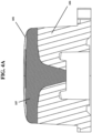
- FIGS. 4A and 4B illustrate respective front and side cross-sectional views of button 105.
- the molding gating of the button 105 may be preferably radially symmetric to create a uniform light ring effect and to prevent overflow between the first 106 and second 107 shots.
- Light-diffusing components that are non-radially symmetric are associated with producing non-uniform light ring effects. For example, where a two-shot light-diffusing button design has been manufactured using a non-radially symmetric tunnel-slide gate positioned on the side of the button, it has been shown that the resulting light ring exhibits a measurably dim region corresponding to the location of the gate.
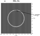
- FIG. 5A illustrates a luminance image 500 of a non-uniform light ring effect where a region 510 is dim when compared to the remainder of the light ring.
- the light ring effect shown in FIG. 5A may be the result of using a non-radially symmetric molding gating.
- the second shot of material 107 may be injected through a molding gate centrally located on the underside of button 105, thereby preserving the radial symmetry of the molding gating.
- the first shot of material 106 may be injected through molding gate 235, which may be located underneath and completely obscured by second shot of material 107.
- FIG. 5B illustrates a luminance image 520 of a uniform light ring effect according to an embodiment of the disclosed subject matter. Notably, the light ring effect shown in FIG. 5B appears uniform without any visible gaps or dim regions.
- annular gap 220 may be referred to as the "cosmetic gap,” since its width affects the cosmetic appearance of the light ring effect. It should be appreciated that where the component with which the ring effect to be achieved is not annular, the surrounding opening may not be annular, but may approximately follow the footprint or perimeter shape of the button, joystick, trackball, or other component.
- a "functional gap" 225 is implemented in addition to the cosmetic gap 220.
- the functional gap 225 may not be included where the component to be illuminated is stationary.
- Functional gap 225 is located directly adjacent to and in between cosmetic gap 220 and interior cavity 315.
- Functional gap 225 allows for constrained movement between button 105 and housing 205. It should be appreciated that the size of functional gap 225 may affect the degree to which button 105 may be shifted laterally by the user. In an extreme case, a user may shift button 105 so that the functional gap 225 is reduced to zero on one side of the button 105 and the functional gap 225 is doubled on the opposite side of the button 105.
- the cosmetic gap 220 is preferably larger at the surface of housing 205 than where the functional gap 225 meets the cosmetic gap 220. In this way, even if a user shifts button 105 laterally to eliminate the functional gap 225, the cosmetic gap 220 may remain, thereby allowing light projected from light-emitting component 210 to reach housing 205 and to maintain the light ring effect.
- the cosmetic gap 200 is of a larger dimension at the exterior surface of housing 205 and tapers to its minimum dimension where it meets functional gap 225.
- functional gap 225 is of a larger dimension where it meets interior cavity 315 and taper to its minimum dimension where it meets cosmetic gap 200 above.
- Both the cosmetic gap 220 and the functional gap 225 each exhibit their respective minimum dimensions where they meet, forming a parting, line and creating a substantially hourglass-shaped gap when viewed together as a whole.
- the maximum dimension of functional gap 225 may be less than the maximum dimension of cosmetic gap 220.
- the cosmetic gap 220 may be between 0.10 and 0.20 millimeters, while functional gap 225 may be in the range of 0.10-0.30 mm, more preferably 0.15-0.25 mm, or more preferably between 0.17 and 0.27 millimeters.
- the functional gap may be approximately 0.15 millimeters, and the cosmetic gap may be approximately 0.22 millimeters.
Landscapes
- Engineering & Computer Science (AREA)
- General Engineering & Computer Science (AREA)
- Push-Button Switches (AREA)
- Switch Cases, Indication, And Locking (AREA)
Claims (13)
- Produit matériel comprenant :un boîtier (205) ayant une ouverture (230) définie par une forme de périmètre ;une carte de circuit imprimé, (310) ;un composant électroluminescent (210) couplé électriquement à la carte de circuit imprimé (310) ;un bouton (105) configuré pour être enfoncé selon un axe d'enfoncement et positionné dans l'ouverture (230) du boîtier (205), le bouton (105) étant espacé du périmètre de l'ouverture (230) du boîtier (205) par un premier espace (220) et un second espace (225) immédiatement adjacent au premier espace (220), le premier espace (220) se rétrécissant jusqu'à une dimension minimale à l'intersection du second espace (225), le bouton (105) étant fabriqué par un procédé de moulage par injection à couches multiples et, pour projeter la lumière à partir du composant électroluminescent (210) uniquement à partir du périmètre du bouton (105), créant ainsi un effet d'anneau lumineux autour du périmètre, comprenant :une première couche (106) de matériau espacée du périmètre de l'ouverture (230) par le premier espace (220) et le second espace (225) et comprenant un premier matériau de diffusion de lumière configuré pour disperser la lumière à partir du composant électroluminescent (210) ; etune seconde couche (107) de matériau comprenant un second matériau optiquement opaque fournissant une surface cosmétique pour le bouton (105),caractérisé en ce qu'une cavité interne (315) est positionnée adjacente au second espace (225), dans lequel la carte de circuit imprimé (310) et le composant électroluminescent (210) sont positionnés à l'intérieur de la cavité interne (315), etdans lequel le second espace (225) est situé entre le premier espace (220) et la cavité interne (315) et permet un mouvement contraint entre le bouton (105) et le boîtier (205) et le premier espace (220), étant plus grand au niveau d'une surface extérieure du boîtier (205) et se rétrécissant jusqu'à la dimension minimale à l'intersection avec le second espace (225), reste de manière à permettre à la lumière d'être projetée à partir du composant électroluminescent (210) d'atteindre le boîtier (205) et de maintenir l'effet d'anneau lumineux même si le second espace (225) est éliminé par un utilisateur déplaçant le bouton (105) dans l'ouverture (230).
- Produit matériel selon la revendication 1, dans lequel le bouton comprend également une porte de moulage radialement symétrique.
- Produit matériel selon la revendication 1, comprenant également :
une bande de silicone résiliente (215) configurée pour provoquer la fermeture d'un circuit lors de l'enfoncement du bouton (105) et pour ramener le bouton (105) à sa position d'origine après avoir été enfoncé, la bande de silicone résiliente (215) ayant une ouverture alignée centralement avec le composant électroluminescent (210) et configurée pour permettre à la lumière du composant électroluminescent de passer à la seconde couche (107). - Produit matériel selon la revendication 1, dans lequel la première couche (106) de matériau est positionnée ou dimensionnée de telle sorte qu'elle dépasse vers l'extérieur du boîtier (205) .
- Produit matériel selon la revendication 1, comprenant également :
un carénage (305) construit à partir d'un matériau optiquement opaque ou semi-opaque et configuré pour entourer au moins une partie du bouton (105). - Produit matériel selon la revendication 1, dans lequel le second espace (225) se rétrécit jusqu'à une dimension minimale à l'intersection avec le premier espace (220), les premier et second espaces (220, 225) formant ainsi une ligne de séparation et créant un espace sensiblement en forme de sablier lorsqu'ils sont vus ensemble dans leur ensemble.
- Produit matériel selon la revendication 1, comprenant également une première porte de moulage par couche disposée en dessous et masquée par la seconde couche (107) de matériau ou une seconde porte de moulage par couche disposée sur et centrée sur la face inférieure du bouton (105).
- Produit matériel selon la revendication 1, dans lequel le premier matériau est un polycarbonate de qualité de diffusion de lumière et/ou le second matériau est au moins l'un parmi le polycarbonate et l'acrylonitrile butadiène styrène.
- Produit matériel selon la revendication 1, dans lequel une dimension maximale du second espace (225) est inférieure à une dimension maximale du premier espace (220).
- Produit matériel selon la revendication 1, dans lequel le bouton (105) est sensiblement centré dans l'ouverture (230) du boîtier (205).
- Produit matériel selon la revendication 1, dans lequel la première couche (106) est configurée pour disperser uniformément la lumière.
- Produit matériel selon la revendication 1, dans lequel une dimension maximale du premier espace (220) se situe dans une plage de 0,20 à 0,24 millimètre et/ou une dimension maximale du second espace (225) se situe dans une plage de 0,14 à 0,16 millimètre.
- Produit matériel selon la revendication 1, dans lequel le composant électroluminescent (210) comprend uniquement un seul composant électroluminescent ou le composant électroluminescent (210) comprend plusieurs composants électroluminescents positionnés dans un diamètre d'un cercle qui est inférieur ou égal à 80 % d'un diamètre d'une surface tournée vers l'extérieur du bouton (105).
Applications Claiming Priority (1)
| Application Number | Priority Date | Filing Date | Title |
|---|---|---|---|
| PCT/US2019/034207 WO2020242458A1 (fr) | 2019-05-28 | 2019-05-28 | Bouton avec anneau d'éclairage |
Publications (2)
| Publication Number | Publication Date |
|---|---|
| EP3762954A1 EP3762954A1 (fr) | 2021-01-13 |
| EP3762954B1 true EP3762954B1 (fr) | 2025-07-02 |
Family
ID=66867824
Family Applications (1)
| Application Number | Title | Priority Date | Filing Date |
|---|---|---|---|
| EP19731062.6A Active EP3762954B1 (fr) | 2019-05-28 | 2019-05-28 | Bouton-poussoir ayant un anneau d'éclairage |
Country Status (5)
| Country | Link |
|---|---|
| US (2) | US11107648B2 (fr) |
| EP (1) | EP3762954B1 (fr) |
| CN (1) | CN112335008B (fr) |
| TW (1) | TWI835937B (fr) |
| WO (1) | WO2020242458A1 (fr) |
Families Citing this family (9)
| Publication number | Priority date | Publication date | Assignee | Title |
|---|---|---|---|---|
| USD951211S1 (en) | 2017-03-16 | 2022-05-10 | Lutron Technology Company Llc | Illuminated control device |
| USD922334S1 (en) | 2017-09-09 | 2021-06-15 | Lutron Technology Company Llc | Keypad |
| USD941783S1 (en) | 2018-06-15 | 2022-01-25 | Lutron Technology Company Llc | Keypad |
| USD951885S1 (en) | 2020-02-10 | 2022-05-17 | Lutron Technology Company Llc | Illuminated control device |
| USD948462S1 (en) | 2020-10-04 | 2022-04-12 | Lutron Technology Company Llc | Control device |
| USD951887S1 (en) * | 2020-10-05 | 2022-05-17 | Lutron Technology Company Llc | Illuminated control device |
| JP2022137900A (ja) * | 2021-03-09 | 2022-09-22 | パナソニックIpマネジメント株式会社 | 照明装置 |
| USD1090567S1 (en) * | 2022-03-21 | 2025-08-26 | Alfred Kaercher Se & Co. Kg | Circular controls surrounding a display screen |
| TWI843158B (zh) * | 2022-07-27 | 2024-05-21 | 緯昌科技股份有限公司 | 具有發光模組之按鍵結構與電子裝置 |
Family Cites Families (26)
| Publication number | Priority date | Publication date | Assignee | Title |
|---|---|---|---|---|
| DE3335275A1 (de) * | 1982-11-08 | 1985-04-18 | Schlegel Georg Fa | Befehlstaster zum einbau in eine schalttafel oder dergleichen |
| US4885443A (en) * | 1988-11-29 | 1989-12-05 | Tokheim Corporation | Sealed backlit switch assembly |
| US5285037A (en) * | 1992-04-10 | 1994-02-08 | Ampex Systems Corp. | Illuminated dome switch |
| US5510782A (en) * | 1992-08-03 | 1996-04-23 | Itt Corporation | Back lit keypad |
| US5711588A (en) * | 1996-09-30 | 1998-01-27 | Ericsson, Inc. | Backlit keypad assembly |
| US5993019A (en) * | 1997-10-03 | 1999-11-30 | Delco Electronics Corporation | Molded two part button with illuminated graphic |
| JP4295468B2 (ja) * | 2001-12-21 | 2009-07-15 | ポリマテック株式会社 | 照光式押釦スイッチ用カバー部材 |
| JP2004079232A (ja) * | 2002-08-12 | 2004-03-11 | Nec Corp | 押しボタンの照光構造と該押しボタンを備えた電子機器 |
| DE50301142D1 (de) * | 2003-04-07 | 2005-10-13 | Feller Ag | Beleuchteter Schalter |
| CN201229874Y (zh) * | 2008-06-30 | 2009-04-29 | 鸿富锦精密工业(深圳)有限公司 | 组合开关 |
| JP4888797B2 (ja) * | 2010-02-18 | 2012-02-29 | Necインフロンティア株式会社 | キーボタン |
| CN201655596U (zh) * | 2010-04-13 | 2010-11-24 | 英华达(上海)科技有限公司 | 一种透光按键的导光结构 |
| GB2487928A (en) * | 2011-02-08 | 2012-08-15 | Visteon Global Tech Inc | Display device for displaying two overlapping graphics independently, in particular on a push button type switch. |
| TWM435704U (en) * | 2012-04-03 | 2012-08-11 | Zhe-Chang Ye | Key switch waterproof structure |
| CN103578831B (zh) * | 2012-08-09 | 2016-07-06 | 光宝电子(广州)有限公司 | 压力式背光按键结构 |
| MX342285B (es) * | 2012-08-30 | 2016-09-23 | Bitron Spa | Dispositivo de control de conmutadores, que comprende al menos dos domos de silicona. |
| US9046414B2 (en) | 2012-09-21 | 2015-06-02 | Google Inc. | Selectable lens button for a hazard detector and method therefor |
| CN203690164U (zh) * | 2013-12-27 | 2014-07-02 | 深圳市巨烽显示科技有限公司 | 带光环的按键结构 |
| DE102014220369A1 (de) * | 2014-10-08 | 2016-04-14 | Continental Automotive Gmbh | Betätigungselement mit Koronabeleuchtung |
| CN204614701U (zh) * | 2015-06-01 | 2015-09-02 | 东莞泰克威科技有限公司 | 一种按键的发光结构 |
| WO2016205989A1 (fr) | 2015-06-23 | 2016-12-29 | 深圳市柔宇科技有限公司 | Module de bouton |
| US10590600B1 (en) * | 2016-01-19 | 2020-03-17 | Apple Inc. | Illumination systems within fabric-based devices |
| CN105742098B (zh) * | 2016-01-28 | 2019-02-01 | 东莞市长资实业有限公司 | 一种光电式线性控制的键盘按键开关 |
| US10515508B2 (en) * | 2017-09-14 | 2019-12-24 | Ags Llc | Push-buttons for gaming machines |
| CN108320969B (zh) * | 2018-02-02 | 2023-09-15 | 佛山市艾佛杜电子科技有限公司 | 一种无声键帽 |
| WO2019171863A1 (fr) * | 2018-03-05 | 2019-09-12 | 信越ポリマー株式会社 | Élément interrupteur à bouton-poussoir |
-
2019
- 2019-05-28 EP EP19731062.6A patent/EP3762954B1/fr active Active
- 2019-05-28 WO PCT/US2019/034207 patent/WO2020242458A1/fr not_active Ceased
- 2019-05-28 CN CN201980005839.5A patent/CN112335008B/zh active Active
- 2019-12-02 TW TW108143866A patent/TWI835937B/zh active
-
2020
- 2020-05-05 US US16/867,147 patent/US11107648B2/en active Active
-
2021
- 2021-08-03 US US17/392,947 patent/US11404226B2/en active Active
Also Published As
| Publication number | Publication date |
|---|---|
| US20200381191A1 (en) | 2020-12-03 |
| CN112335008A (zh) | 2021-02-05 |
| US20210366670A1 (en) | 2021-11-25 |
| US11404226B2 (en) | 2022-08-02 |
| WO2020242458A1 (fr) | 2020-12-03 |
| TW202107500A (zh) | 2021-02-16 |
| CN112335008B (zh) | 2023-10-31 |
| US11107648B2 (en) | 2021-08-31 |
| TWI835937B (zh) | 2024-03-21 |
| EP3762954A1 (fr) | 2021-01-13 |
Similar Documents
| Publication | Publication Date | Title |
|---|---|---|
| US11404226B2 (en) | Button with illumination ring | |
| US20200401234A1 (en) | Input Device | |
| CN206147528U (zh) | 键、照明结构、键盘以及电子设备 | |
| JP4295468B2 (ja) | 照光式押釦スイッチ用カバー部材 | |
| JP5635108B2 (ja) | 表示パネル及び該表示素子の半透明支持要素の製造 | |
| US20210010480A1 (en) | Illumination fan | |
| TWI779292B (zh) | 搖桿模組 | |
| TW201310282A (zh) | 發光鍵盤 | |
| TWM541104U (zh) | 應用於發光鍵盤之背光模組及發光鍵盤 | |
| WO2016062124A1 (fr) | Composant de guide de lumière, appareil à touches, et panneau de commande | |
| US7687731B2 (en) | Illuminated push button unit | |
| JP3649637B2 (ja) | 電子機器の照光構造 | |
| CN103000424A (zh) | 发光键盘 | |
| CA2742874C (fr) | Interrupteur electrique | |
| CN214797200U (zh) | 一种防漏光开关 | |
| US9070520B2 (en) | Illumination module and illuminated keyboard having the same | |
| TWI395245B (zh) | 具發光亮度變化的按鍵裝置 | |
| CN207993743U (zh) | 一种用于键盘开关的透光盖子组件 | |
| JP2007080763A (ja) | 照光式押釦スイッチ用カバー部材及びその製造方法 | |
| CN219713158U (zh) | 发光组件以及用电装置 | |
| CN102087924A (zh) | 按钮装置 | |
| CN220911201U (zh) | 发光装置及车辆 | |
| CN223052016U (zh) | 外壳组件、按键板机构和家用电器 | |
| JP6518962B2 (ja) | 加飾照光部材 | |
| CN220774180U (zh) | 按键装置及电子设备 |
Legal Events
| Date | Code | Title | Description |
|---|---|---|---|
| STAA | Information on the status of an ep patent application or granted ep patent |
Free format text: STATUS: UNKNOWN |
|
| STAA | Information on the status of an ep patent application or granted ep patent |
Free format text: STATUS: THE INTERNATIONAL PUBLICATION HAS BEEN MADE |
|
| PUAI | Public reference made under article 153(3) epc to a published international application that has entered the european phase |
Free format text: ORIGINAL CODE: 0009012 |
|
| STAA | Information on the status of an ep patent application or granted ep patent |
Free format text: STATUS: REQUEST FOR EXAMINATION WAS MADE |
|
| 17P | Request for examination filed |
Effective date: 20200424 |
|
| AK | Designated contracting states |
Kind code of ref document: A1 Designated state(s): AL AT BE BG CH CY CZ DE DK EE ES FI FR GB GR HR HU IE IS IT LI LT LU LV MC MK MT NL NO PL PT RO RS SE SI SK SM TR |
|
| AX | Request for extension of the european patent |
Extension state: BA ME |
|
| RIN1 | Information on inventor provided before grant (corrected) |
Inventor name: DUNCAN, SCOTT Inventor name: POH, CHEE SEN Inventor name: LAIZ, JACQUELINE Inventor name: GUPTA, ANURAG Inventor name: DOBLACK, SHELOMON Inventor name: WROBLEWSKI, ALEXANDER |
|
| DAV | Request for validation of the european patent (deleted) | ||
| DAX | Request for extension of the european patent (deleted) | ||
| STAA | Information on the status of an ep patent application or granted ep patent |
Free format text: STATUS: EXAMINATION IS IN PROGRESS |
|
| 17Q | First examination report despatched |
Effective date: 20221213 |
|
| GRAP | Despatch of communication of intention to grant a patent |
Free format text: ORIGINAL CODE: EPIDOSNIGR1 |
|
| STAA | Information on the status of an ep patent application or granted ep patent |
Free format text: STATUS: GRANT OF PATENT IS INTENDED |
|
| INTG | Intention to grant announced |
Effective date: 20250127 |
|
| GRAS | Grant fee paid |
Free format text: ORIGINAL CODE: EPIDOSNIGR3 |
|
| GRAA | (expected) grant |
Free format text: ORIGINAL CODE: 0009210 |
|
| STAA | Information on the status of an ep patent application or granted ep patent |
Free format text: STATUS: THE PATENT HAS BEEN GRANTED |
|
| P01 | Opt-out of the competence of the unified patent court (upc) registered |
Free format text: CASE NUMBER: APP_19937/2025 Effective date: 20250425 |
|
| AK | Designated contracting states |
Kind code of ref document: B1 Designated state(s): AL AT BE BG CH CY CZ DE DK EE ES FI FR GB GR HR HU IE IS IT LI LT LU LV MC MK MT NL NO PL PT RO RS SE SI SK SM TR |
|
| REG | Reference to a national code |
Ref country code: GB Ref legal event code: FG4D |
|
| REG | Reference to a national code |
Ref country code: CH Ref legal event code: EP |
|
| REG | Reference to a national code |
Ref country code: DE Ref legal event code: R096 Ref document number: 602019071926 Country of ref document: DE |
|
| REG | Reference to a national code |
Ref country code: IE Ref legal event code: FG4D |
|
| REG | Reference to a national code |
Ref country code: NL Ref legal event code: MP Effective date: 20250702 |
|
| PG25 | Lapsed in a contracting state [announced via postgrant information from national office to epo] |
Ref country code: PT Free format text: LAPSE BECAUSE OF FAILURE TO SUBMIT A TRANSLATION OF THE DESCRIPTION OR TO PAY THE FEE WITHIN THE PRESCRIBED TIME-LIMIT Effective date: 20251103 |
|
| PG25 | Lapsed in a contracting state [announced via postgrant information from national office to epo] |
Ref country code: NL Free format text: LAPSE BECAUSE OF FAILURE TO SUBMIT A TRANSLATION OF THE DESCRIPTION OR TO PAY THE FEE WITHIN THE PRESCRIBED TIME-LIMIT Effective date: 20250702 |
|
| REG | Reference to a national code |
Ref country code: AT Ref legal event code: MK05 Ref document number: 1810256 Country of ref document: AT Kind code of ref document: T Effective date: 20250702 |
|
| PG25 | Lapsed in a contracting state [announced via postgrant information from national office to epo] |
Ref country code: IS Free format text: LAPSE BECAUSE OF FAILURE TO SUBMIT A TRANSLATION OF THE DESCRIPTION OR TO PAY THE FEE WITHIN THE PRESCRIBED TIME-LIMIT Effective date: 20251102 |
|
| PG25 | Lapsed in a contracting state [announced via postgrant information from national office to epo] |
Ref country code: NO Free format text: LAPSE BECAUSE OF FAILURE TO SUBMIT A TRANSLATION OF THE DESCRIPTION OR TO PAY THE FEE WITHIN THE PRESCRIBED TIME-LIMIT Effective date: 20251002 |
|
| REG | Reference to a national code |
Ref country code: LT Ref legal event code: MG9D |
|
| PG25 | Lapsed in a contracting state [announced via postgrant information from national office to epo] |
Ref country code: AT Free format text: LAPSE BECAUSE OF FAILURE TO SUBMIT A TRANSLATION OF THE DESCRIPTION OR TO PAY THE FEE WITHIN THE PRESCRIBED TIME-LIMIT Effective date: 20250702 |
|
| PG25 | Lapsed in a contracting state [announced via postgrant information from national office to epo] |
Ref country code: FI Free format text: LAPSE BECAUSE OF FAILURE TO SUBMIT A TRANSLATION OF THE DESCRIPTION OR TO PAY THE FEE WITHIN THE PRESCRIBED TIME-LIMIT Effective date: 20250702 |
|
| PG25 | Lapsed in a contracting state [announced via postgrant information from national office to epo] |
Ref country code: HR Free format text: LAPSE BECAUSE OF FAILURE TO SUBMIT A TRANSLATION OF THE DESCRIPTION OR TO PAY THE FEE WITHIN THE PRESCRIBED TIME-LIMIT Effective date: 20250702 |
|
| PG25 | Lapsed in a contracting state [announced via postgrant information from national office to epo] |
Ref country code: GR Free format text: LAPSE BECAUSE OF FAILURE TO SUBMIT A TRANSLATION OF THE DESCRIPTION OR TO PAY THE FEE WITHIN THE PRESCRIBED TIME-LIMIT Effective date: 20251003 |
|
| PG25 | Lapsed in a contracting state [announced via postgrant information from national office to epo] |
Ref country code: CZ Free format text: LAPSE BECAUSE OF FAILURE TO SUBMIT A TRANSLATION OF THE DESCRIPTION OR TO PAY THE FEE WITHIN THE PRESCRIBED TIME-LIMIT Effective date: 20250702 Ref country code: SE Free format text: LAPSE BECAUSE OF FAILURE TO SUBMIT A TRANSLATION OF THE DESCRIPTION OR TO PAY THE FEE WITHIN THE PRESCRIBED TIME-LIMIT Effective date: 20250702 |
|
| PG25 | Lapsed in a contracting state [announced via postgrant information from national office to epo] |
Ref country code: LV Free format text: LAPSE BECAUSE OF FAILURE TO SUBMIT A TRANSLATION OF THE DESCRIPTION OR TO PAY THE FEE WITHIN THE PRESCRIBED TIME-LIMIT Effective date: 20250702 |
|
| PG25 | Lapsed in a contracting state [announced via postgrant information from national office to epo] |
Ref country code: PL Free format text: LAPSE BECAUSE OF FAILURE TO SUBMIT A TRANSLATION OF THE DESCRIPTION OR TO PAY THE FEE WITHIN THE PRESCRIBED TIME-LIMIT Effective date: 20250702 Ref country code: BG Free format text: LAPSE BECAUSE OF FAILURE TO SUBMIT A TRANSLATION OF THE DESCRIPTION OR TO PAY THE FEE WITHIN THE PRESCRIBED TIME-LIMIT Effective date: 20250702 |
|
| PG25 | Lapsed in a contracting state [announced via postgrant information from national office to epo] |
Ref country code: RS Free format text: LAPSE BECAUSE OF FAILURE TO SUBMIT A TRANSLATION OF THE DESCRIPTION OR TO PAY THE FEE WITHIN THE PRESCRIBED TIME-LIMIT Effective date: 20251002 |
|
| PG25 | Lapsed in a contracting state [announced via postgrant information from national office to epo] |
Ref country code: ES Free format text: LAPSE BECAUSE OF FAILURE TO SUBMIT A TRANSLATION OF THE DESCRIPTION OR TO PAY THE FEE WITHIN THE PRESCRIBED TIME-LIMIT Effective date: 20250702 |
|
| PG25 | Lapsed in a contracting state [announced via postgrant information from national office to epo] |
Ref country code: SM Free format text: LAPSE BECAUSE OF FAILURE TO SUBMIT A TRANSLATION OF THE DESCRIPTION OR TO PAY THE FEE WITHIN THE PRESCRIBED TIME-LIMIT Effective date: 20250702 |
|
| PG25 | Lapsed in a contracting state [announced via postgrant information from national office to epo] |
Ref country code: DK Free format text: LAPSE BECAUSE OF FAILURE TO SUBMIT A TRANSLATION OF THE DESCRIPTION OR TO PAY THE FEE WITHIN THE PRESCRIBED TIME-LIMIT Effective date: 20250702 |
|
| PG25 | Lapsed in a contracting state [announced via postgrant information from national office to epo] |
Ref country code: IT Free format text: LAPSE BECAUSE OF FAILURE TO SUBMIT A TRANSLATION OF THE DESCRIPTION OR TO PAY THE FEE WITHIN THE PRESCRIBED TIME-LIMIT Effective date: 20250702 |
|
| PG25 | Lapsed in a contracting state [announced via postgrant information from national office to epo] |
Ref country code: EE Free format text: LAPSE BECAUSE OF FAILURE TO SUBMIT A TRANSLATION OF THE DESCRIPTION OR TO PAY THE FEE WITHIN THE PRESCRIBED TIME-LIMIT Effective date: 20250702 Ref country code: SK Free format text: LAPSE BECAUSE OF FAILURE TO SUBMIT A TRANSLATION OF THE DESCRIPTION OR TO PAY THE FEE WITHIN THE PRESCRIBED TIME-LIMIT Effective date: 20250702 |