EP3763190A1 - Reinigungssystem und verfahren zur steuerung des reinigungssystems - Google Patents
Reinigungssystem und verfahren zur steuerung des reinigungssystems Download PDFInfo
- Publication number
- EP3763190A1 EP3763190A1 EP20181991.9A EP20181991A EP3763190A1 EP 3763190 A1 EP3763190 A1 EP 3763190A1 EP 20181991 A EP20181991 A EP 20181991A EP 3763190 A1 EP3763190 A1 EP 3763190A1
- Authority
- EP
- European Patent Office
- Prior art keywords
- cleaning
- dirt
- mower
- work
- autonomous traveling
- Prior art date
- Legal status (The legal status is an assumption and is not a legal conclusion. Google has not performed a legal analysis and makes no representation as to the accuracy of the status listed.)
- Granted
Links
Images


Classifications
-
- A—HUMAN NECESSITIES
- A01—AGRICULTURE; FORESTRY; ANIMAL HUSBANDRY; HUNTING; TRAPPING; FISHING
- A01D—HARVESTING; MOWING
- A01D34/00—Mowers; Mowing apparatus of harvesters
- A01D34/001—Accessories not otherwise provided for
- A01D34/003—Means for cleaning the machine
-
- A—HUMAN NECESSITIES
- A01—AGRICULTURE; FORESTRY; ANIMAL HUSBANDRY; HUNTING; TRAPPING; FISHING
- A01D—HARVESTING; MOWING
- A01D34/00—Mowers; Mowing apparatus of harvesters
- A01D34/006—Control or measuring arrangements
- A01D34/008—Control or measuring arrangements for automated or remotely controlled operation
-
- B—PERFORMING OPERATIONS; TRANSPORTING
- B08—CLEANING
- B08B—CLEANING IN GENERAL; PREVENTION OF FOULING IN GENERAL
- B08B13/00—Accessories or details of general applicability for machines or apparatus for cleaning
-
- B—PERFORMING OPERATIONS; TRANSPORTING
- B08—CLEANING
- B08B—CLEANING IN GENERAL; PREVENTION OF FOULING IN GENERAL
- B08B3/00—Cleaning by methods involving the use or presence of liquid or steam
- B08B3/04—Cleaning involving contact with liquid
-
- A—HUMAN NECESSITIES
- A01—AGRICULTURE; FORESTRY; ANIMAL HUSBANDRY; HUNTING; TRAPPING; FISHING
- A01D—HARVESTING; MOWING
- A01D2101/00—Lawn-mowers
-
- A—HUMAN NECESSITIES
- A01—AGRICULTURE; FORESTRY; ANIMAL HUSBANDRY; HUNTING; TRAPPING; FISHING
- A01D—HARVESTING; MOWING
- A01D34/00—Mowers; Mowing apparatus of harvesters
- A01D34/01—Mowers; Mowing apparatus of harvesters characterised by features relating to the type of cutting apparatus
- A01D34/412—Mowers; Mowing apparatus of harvesters characterised by features relating to the type of cutting apparatus having rotating cutters
- A01D34/63—Mowers; Mowing apparatus of harvesters characterised by features relating to the type of cutting apparatus having rotating cutters having cutters rotating about a vertical axis
- A01D34/76—Driving mechanisms for the cutters
- A01D34/78—Driving mechanisms for the cutters electric
Definitions
- the present invention relates to a cleaning system and a method of controlling a cleaning system.
- An autonomous traveling work machine has been known which works while autonomously traveling (see, for example, Japanese Patent Laid-Open No. 2016-218733 ).
- the autonomous traveling work machine disclosed in Japanese Patent Laid-Open No. 2016-218733 includes wheels and is capable of traveling autonomously based on peripheral information. Furthermore, a cleaning area where the wheels are cleaned is equipped with a cleaning mat that cleans the wheels as the wheels turn to rub against the cleaning mat. Furthermore, the autonomous traveling work machine includes a controller that controls an operation of the autonomous traveling work machine so as to execute a cleaning process of the wheels in the cleaning area.
- a mower As an autonomous traveling work machine, a mower has been known which executes a mowing work while traveling autonomously. In the mower, pieces of mowed grass may adhere to the periphery of a cutting blade disc that is disposed on a lower portion of a mower main body.
- pieces of the mowed grass may contain water and heavily and firmly adhere to the lower portion of the mower main body.
- a user has used a hose or the like to apply water to the lower portion of the mower main body, washing off the dirt.
- An aspect of the present invention has an object to provide: a cleaning system that is capable of determining at least one of a necessity of cleaning and a method of cleaning, according to a state of dirt of an autonomous traveling work machine; and a method of controlling a cleaning system.
- An aspect of the present invention is a cleaning system including: an autonomous traveling work machine executing a predetermined work while traveling autonomously; and a cleaning station cleaning the autonomous traveling work machine, and the cleaning system includes: an acquirer acquiring dirt information relating to a state of dirt of the autonomous traveling work machine; a determiner determining at least one of a necessity of cleaning the autonomous traveling work machine and a method of cleaning the autonomous traveling work machine, based on the dirt information; and a cleaning executor executing a cleaning operation, according to a determination result of the determiner.
- An aspect of the present invention is the above cleaning system, wherein the acquirer acquires a work history of the autonomous traveling work machine, as the dirt information, and the work history includes at least one of a work frequency, a work time, and a travel distance during work.
- An aspect of the present invention is the above cleaning system including a detector detecting dirt of the autonomous traveling work machine, wherein the acquirer acquires information indicating the dirt being detected by the detector, as the dirt information.
- An aspect of the present invention is the above cleaning system, wherein at least one of the autonomous traveling work machine and the cleaning station includes an imaging unit as part of the detector, and the imaging unit generates the dirt image.
- An aspect of the present invention is the above cleaning system, wherein the autonomous traveling work machine is driven to travel by a driving wheel, the driving wheel being driven by a second motor, and the acquirer acquires a value of at least one of a power consumption, a load voltage, and a load current of the second motor, as the dirt information.
- An aspect of the present invention is the above cleaning system, wherein the acquirer acquires a value of at least one of the power consumption, the load voltage, and the load current of the second motor when the autonomous traveling work machine moves to the cleaning station, as the dirt information.
- An aspect of the present invention is the above cleaning system, wherein the autonomous traveling work machine is driven to travel by a driving wheel, and the acquirer acquires a slip ratio of the driving wheel, as the dirt information.
- An aspect of the present invention is the above cleaning system, wherein the acquirer acquires the slip ratio when the autonomous traveling work machine moves to the cleaning station, as the dirt information.
- An aspect of the present invention is the above cleaning system, wherein the acquirer acquires at least one of weather, temperature, and humidity when the autonomous traveling work machine executes the predetermined work, as the dirt information.
- An aspect of the present invention is the above cleaning system, wherein when the autonomous traveling work machine executes the predetermined work, the acquirer acquires work information of a work device affecting dirt of the autonomous traveling work machine, as the dirt information.
- An aspect of the present invention is the above cleaning system, wherein the autonomous traveling work machine is a mower executing a mowing work for mowing a lawn growing in a predetermined area, and the work device is a sprinkler being disposed at the predetermined area and spreading water on the lawn.
- the autonomous traveling work machine is a mower executing a mowing work for mowing a lawn growing in a predetermined area
- the work device is a sprinkler being disposed at the predetermined area and spreading water on the lawn.
- An aspect of the present invention is a method of controlling a cleaning system including: an autonomous traveling work machine executing a predetermined work while traveling autonomously; and a cleaning station cleaning the autonomous traveling work machine, and the method acquires dirt information relating to a state of dirt of the autonomous traveling work machine; determines at least one of a necessity of cleaning the autonomous traveling work machine and a method of cleaning the autonomous traveling work machine, based on the dirt information; and executes a cleaning operation, according to a result of the determination.
- An aspect of the present invention can determine at least one of the necessity of cleaning and the method of cleaning, according to a state of dirt of the autonomous traveling work machine.
- FIG. 1 is a view showing a configuration of a mowing system 1 according to the present embodiment.
- the mowing system 1 includes a plurality of (for example, two) robotic mowers 2, embodiments of the present invention are not limited to this.
- the mowing system 1 may include only one robotic mower 2.
- the robotic mower 2 may cause a first imaging device 19 to detect the area wire 5, detecting the boundary A of the mowing area AR.
- the first imaging device 19 will be explained later in detail with reference to FIG. 2 .
- the cleaning station 3 is installed in the mowing area AR and supplies the robotic mower 2 with tap water.
- the cleaning station 3 includes a control board 31.
- the control board 31 will be explained later in detail with reference to FIG. 3 .
- the cleaning station 3 is also a standby location of the robotic mower 2 at the time of non-working. At the end of the mowing work, the robotic mower 2 autonomously travels to return to the cleaning station 3 and is cleaned as necessary at the cleaning station 3.
- Each of the plurality of sprinklers 4 is installed in the mowing area AR and spreads water on a lawn growing in the mowing area AR.
- Each of the plurality of sprinklers 4 spreads water for a certain period of time, for example, every time a predetermined time elapses.
- the predetermined time is, for example, 6 hours, and the certain period of time is, for example, 10 minutes.
- the plurality of sprinklers 4 correspond to one example of a "work device.”
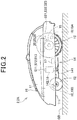
- FIG. 2 is a side view showing one example of a configuration of the robotic mower 2 according to the present embodiment.
- the robotic mower 2 may be referred to as a mower 2 in the following explanation.
- the mower 2 includes a mower main body 2A and a first controller 20.
- the first controller 20 controls an operation of the mower main body 2A.
- the mower main body 2A includes a housing 11, right and left front wheels 12 that are provided at a front portion of the housing 11, right and left rear wheels 13 that are provided at a rear portion of the housing 11, and a work unit 14 that is provided at a lower center portion of the housing 11.
- the work unit 14 includes a work unit driving motor 142 and a cutting blade disc 141 with a cutting blade being provided on a circular plate-shaped disc, and the work unit driving motor 142 rotationally drives the cutting blade disc 141, cutting grass.
- the mower main body 2A includes right and left traveling motors 15, a lifting and lowering mechanism 16, a battery 17, a vehicle speed sensor 18, the first imaging device 19, a first communicator 25, and a charger 26.
- the housing 11 stores the right and left traveling motors 15, the work unit driving motor 142, the lifting and lowering mechanism 16, the battery 17, the vehicle speed sensor 18, the first controller 20, the first communicator 25, and the charger 26.
- the housing 11 has a bottom surface 111.
- Each of the right and left traveling motors 15 drives the mower 2 to travel. Specifically, the right and left traveling motors 15 individually drive the respective right and left rear wheels 13. The traveling motor 15 drives the rear wheel 13 according to an instruction that is issued by the first controller 20, causing the mower 2 to travel. The traveling motor 15 corresponds to one example of a "second motor.”
- Each of the traveling motors 15 is equipped with a second power sensor S21, a second voltage sensor S22, and a second current sensor S23.
- the second power sensor S21 detects a power consumption of the traveling motor 15 during traveling of the mower 2.
- the second voltage sensor S22 detects a load voltage that is applied to the traveling motor 15 during traveling of the mower 2.
- the second current sensor S23 detects a load current that flows to the traveling motor 15 during traveling of the mower 2.
- a detection signal of each of the second power sensor S21, the second voltage sensor S22, and the second current sensor S23 is transmitted to the first controller 20.
- the work unit driving motor 142 drives the cutting blade disc 141 and the lifting and lowering mechanism 16. According to an instruction that is issued by the first controller 20, the traveling motor 15 drives the mower 2 to travel, and the work unit driving motor 142 rotationally drives the cutting blade disc 141, executing the mowing work.
- the mowing work corresponds to one example of a "predetermined work.”
- the work unit driving motor 142 corresponds to one example of a "first motor.” According to an instruction that is issued by the first controller 20, the work unit driving motor 142 drives the lifting and lowering mechanism 16, lifting and lowering the cutting blade disc 141.
- the work unit driving motor 142 is equipped with a first power sensor S11, a first voltage sensor S12, and a first current sensor S13.
- the first power sensor S11 detects a power consumption of the work unit driving motor 142 during rotation of the cutting blade disc 141.
- the first voltage sensor S12 detects a load voltage that is applied to the work unit driving motor 142 during rotation of the cutting blade disc 141.
- the first current sensor S13 detects a load current that flows to the work unit driving motor 142 during rotation of the cutting blade disc 141.
- a detection signal of each of the first power sensor S11, the first voltage sensor S12, and the first current sensor S13 is transmitted to the first controller 20.
- the lifting and lowering mechanism 16 lifts and lowers the cutting blade disc 141.
- the battery 17 supplies each unit of the mower 2 with operation power.
- the vehicle speed sensor 18 includes a driving wheel vehicle speed sensor 18A and a driven wheel vehicle speed sensor 18B.
- the driving wheel vehicle speed sensor 18A detects a driving wheel vehicle speed VD corresponding to a peripheral speed of the right and left rear wheels 13 that are driving wheels.
- the driven wheel vehicle speed sensor 18B detects a driven wheel vehicle speed VN corresponding to a peripheral speed of the right and left front wheels 12 that are driven wheels.
- a detection signal of each of the driving wheel vehicle speed sensor 18A and the driven wheel vehicle speed sensor 18B is transmitted to the first controller 20.
- the first imaging device 19 includes a charge coupled device (CCD) image sensor, a complementary metal-oxide-semiconductor (CMOS) image sensor, or the like and generates a forward image of the mower 2. An image signal that is generated by the first imaging device 19 is transmitted to the first controller 20.
- CCD charge coupled device
- CMOS complementary metal-oxide-semiconductor
- the first controller 20 controls an operation of each unit of the mower 2. Specifically, the first controller 20 controls an operation of the mower 2 so that the mower 2 is cleaned. A configuration of the first controller 20 will be explained later in detail with reference to FIG. 5 .
- the first communicator 25 communicates with a second communicator 312 of the cleaning station 3. Specifically, the first communicator 25 communicates with the second communicator 312 by, for example, wireless communication such as Bluetooth (registered trademark).
- the second communicator 312 will be explained later in detail with reference to FIG. 3 .
- the charger 26 charges the battery 17. Specifically, the charger 26 is supplied with AC power from a power supplier 34 and converts the AC power into DC power, charging the battery 17. It should be noted that although in the present embodiment, a case is explained in which the charger 26 converts AC power into DC power, the power supplier 34 may convert AC power into DC power. The power supplier 34 will be explained later in detail with reference to FIG. 3 .
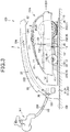
- FIG. 3 is a side view showing one example of a configuration of a cleaning system 100.
- the cleaning system 100 includes the cleaning station 3 and the mower 2.
- the cleaning system 100 cleans the mower 2.
- the cleaning station 3 includes an arch member 30, the control board 31, a water supplier 32, a placement base 33, the power supplier 34, a sliding member 35, an electric valve 36, a second imaging device 37, and an air blowing mechanism 38.
- the arch member 30 forms an arch shape so as to cover the mower 2 when the mower 2 is placed on the placement base 33.
- the arch member 30 is equipped with the control board 31, the water supplier 32, the power supplier 34, the electric valve 36, and the second imaging device 37.
- the control board 31 controls an operation of the cleaning station 3.
- the control board 31 is equipped with a second controller 311 and the second communicator 312.
- the second controller 311 controls the operation of the cleaning station 3. A configuration of the second controller 311 will be explained later in detail with reference to FIG. 5 .
- the second communicator 312 communicates with the first communicator 25 of the mower 2. Specifically, the second communicator 312 communicates with the first communicator 25 by, for example, wireless communication such as Bluetooth (registered trademark).
- the water supplier 32 supplies the mower 2 with the tap water.
- the water supplier 32 includes an inflow opening 321, a second flow path 322, and an outflow opening 323.
- the inflow opening 321 is supplied with the tap water from a faucet WT via a hose HS.
- the second flow path 322 causes the tap water that is supplied to the inflow opening 321 to flow to the outflow opening 323.
- the outflow opening 323 supplies a water receiver 21 that is disposed on an upper portion of the mower 2 with the tap water that is supplied from the second flow path 322.
- the electric valve 36 is disposed on the second flow path 322 and, according to an instruction that is issued by the second controller 311, blocks or releases the flow of the tap water that is supplied from the faucet WT via the hose HS. Specifically, when washing processing of the mower 2 is executed, the flow of the tap water is released, and when the washing processing of the mower 2 is not executed, the flow of the tap water is blocked.
- the second imaging device 37 is disposed downward at an end of the arch member 30 and includes a CCD image sensor, a CMOS image sensor, or the like, generating a dirt image indicating dirt of the mower 2.
- the cleaning station 3 is equipped with a reflection mirror, and via the reflection mirror, the second imaging device 37 generates a dirt image indicating dirt of the bottom surface 111 of the housing 11, a peripheral surface of the front wheel 12, a peripheral surface of the rear wheel 13, and the like.
- the first imaging device 19 also generates a dirt image indicating dirt of the bottom surface 111 of the housing 11, the peripheral surface of the front wheel 12, the peripheral surface of the rear wheel 13, and the like, via the reflection mirror that is equipped on the cleaning station 3.
- Each of the first imaging device 19 and the second imaging device 37 corresponds to one example of an “imaging unit.” Furthermore, each of the first imaging device 19 and the second imaging device 37 configures part of a "detector.”
- each of the first imaging device 19 and the second imaging device 37 generates a dirt image
- the first imaging device 19 or the second imaging device 37 may generate a dirt image.
- the mower 2 On the placement base 33, the mower 2 is placed.
- the outflow opening 323 and the water receiver 21 are disposed such that when the mower 2 is placed on the placement base 33, the water supplier 32 supplies the water receiver 21 with the tap water.
- One end of the placement base 33 is fixed to a base end of the arch member 30.
- the one end of the placement base 33 is a left end of the placement base 33 in FIG. 3 .
- An upper surface of the other end of the placement base 33 has irregularities so as to allow the mower 2 to easily move onto the placement base 33.
- the other end of the placement base 33 is a right end of the placement base 33 in FIG. 3 .
- the sliding member 35 is fixed and a nozzle of the air blowing mechanism 38 is disposed.
- the sliding member 35 includes, for example, a brush. Furthermore, the sliding member 35 may be a columnar-shaped brush that is configured to be rotatable.
- the sliding member 35 includes a first sliding member 351, a second sliding member 352, and a third sliding member 353.
- the first sliding member 351 slides on a front portion of the bottom surface 111 of the housing 11 and the peripheral surface of the front wheel 12.
- the second sliding member 352 slides on center and rear portions of the bottom surface 111 of the housing 11.
- the front portion of the bottom surface 111 indicates a portion on the left side of the bottom surface 111 in FIG. 3
- the rear portion of the bottom surface 111 indicates a portion on the right side of the bottom surface 111 in FIG. 3
- the third sliding member 353 slides on the peripheral surface of the rear wheel 13.
- the air blowing mechanism 38 discharges air upward from the upper surface of the placement base 33.
- the air blowing mechanism 38 is supplied with compressed air and discharges the compressed air from a plurality of nozzles that are disposed on the upper surface of the placement base 33.
- Each of the plurality of nozzles is disposed on the upper surface of the placement base 33 so as to discharge the compressed air toward the cleaning target portions such as the bottom surface 111 of the housing 11, the peripheral surface of the front wheel 12, and the peripheral surface of the rear wheel 13.
- the cleaning station 3 electrically connects to the mower 2. In other words, when the mower 2 is placed at a predetermined position of the placement base 33, power is supplied to the mower 2 from the cleaning station 3.
- the power supplier 34 supplies the mower 2 with the power. Specifically, the power supplier 34 supplies the charger 26 of the mower 2 with the power.
- the power supplier 34 is supplied with AC power from a commercial power source.
- the mower 2 includes the water receiver 21 and a first flow path 22.
- the water receiver 21 is disposed on an upper portion of the housing 11 and receives the tap water that is supplied from the water supplier 32.
- the water receiver 21 includes an upper surface opening 211.
- the water receiver 21 forms, for example, a box shape, and an upper surface thereof forms the upper surface opening 211.
- the tap water that flows out of the outflow opening 323 of the water supplier 32 flows into the water receiver 21 via the upper surface opening 211.
- the first flow path 22 causes the tap water that flows into the water receiver 21 to flow toward the work unit 14.
- the first flow path 22 is formed along an up-down direction inside the mower main body 2A.
- a spreading member 144 causes the tap water that flows in from the first flow path 22 to flow out from between the cutting blade disc 141 of the work unit 14 and the bottom surface 111 of the housing 11. The spreading member 144 will be explained later in detail with reference to FIG. 4 .
- FIG. 4 is a side cross-sectional view showing one example of a configuration of the spreading member 144.
- the work unit 14 includes a driving shaft 143 and the spreading member 144.
- the driving shaft 143 forms a columnar shape and transmits a rotational torque of the work unit driving motor 142 to the cutting blade disc 141.
- the work unit driving motor 142 rotationally drives the cutting blade disc 141 via the driving shaft 143.
- the spreading member 144 spreads the tap water on the cutting blade disc 141.
- the spreading member 144 forms a cylindrical shape, is disposed around the driving shaft 143, and has an opening QP that causes the tap water to flow out.
- the tap water flows from the first flow path 22 into a gap between the spreading member 144 and the driving shaft 143. Then, the tap water flows out of the opening QP.
- the spreading member 144 is rotationally driven by the work unit driving motor 142.
- the spreading member 144 and the driving shaft 143 are integrated, and in such an integrated manner, the spreading member 144 and the driving shaft 143 are rotationally driven by the work unit driving motor 142.
- the spreading member 144 and the driving shaft 143 are rotationally driven by the work unit driving motor 142 in the integrated manner, causing the tap water that flows into the gap between the spreading member 144 and the driving shaft 143 to flow out of the opening QP in a direction DW by centrifugal force.
- the direction DW indicates a direction in which the tap water flows out of the opening QP.
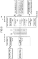
- FIG. 5 is a view showing one examples of configurations of the first controller 20 and the second controller 311.
- the first controller 20 has, for example, a first processor 20A such as a central processing unit (CPU) and a memory 20B such as a random access memory (RAM) or a read only memory (ROM).
- the memory 20B stores work target area related map data, mowing work schedule data, and data of, for example, a first control program.
- the first processor 20A executes the first control program to function as a first transceiver 201, a detector 202, an acquirer 203, a determiner 204, and a first cleaning executor 205. Furthermore, the first processor 20A executes the first control program to cause the memory 20B to function as a history storage 206.
- the history storage 206 stores information indicating a work frequency WN, information indicating a work time WH, and information indicating a travel distance WL during work. It should be noted that the information indicating the work frequency WN, the information indicating the work time WH, and the information indicating the travel distance WL during work are recorded in the history storage 206 by the first controller 20 and read out by the acquirer 203.
- the work frequency WN indicates a number of times the mower 2 executes the mowing work. Specifically, when the first cleaning executor 205 executes cleaning, the first controller 20 resets the work frequency WN. In other words, after cleaning is executed, the work frequency WN indicates the number of times the mower 2 executes the mowing work.
- the work time WH indicates an integrated value of a time during which the mower 2 executes the mowing work. Specifically, when the first cleaning executor 205 executes cleaning, the first controller 20 resets the work time WH. In other words, after cleaning is executed, the work time WH indicates the integrated value of the time during which the mower 2 executes the mowing work.
- the travel distance WL indicates an integrated value of a distance in which the mower 2 travels during execution of the mowing work. Specifically, when the first cleaning executor 205 executes cleaning, the first controller 20 resets the travel distance WL. In other words, after cleaning is executed, the travel distance WL indicates the integrated value of the distance in which the mower 2 travels during execution of the mowing work.
- the history storage 206 stores information indicating a dirt image that is generated by each of the first imaging device 19 and the second imaging device 37. It should be noted that the information indicating a dirt image that is generated by the second imaging device 37 is acquired by the first controller 20 via the second controller 311 and the second communicator 312 in this order.
- the history storage 206 stores information indicating the driving wheel vehicle speed VD that is detected by the driving wheel vehicle speed sensor 18A, and information indicating the driven wheel vehicle speed VN that is detected by the driven wheel vehicle speed sensor 18B. It should be noted that when the mower 2 moves to the cleaning station 3, the driving wheel vehicle speed VD and the driven wheel vehicle speed VN are acquired by the first controller 20 from the driving wheel vehicle speed sensor 18A and the driven wheel vehicle speed sensor 18B.
- the history storage 206 stores information indicating a power value that is detected by the first power sensor S11, information indicating a voltage value that is detected by the first voltage sensor S12, and information indicating a current value that is detected by the first current sensor S13. Furthermore, the history storage 206 stores information indicating a power value that is detected by the second power sensor S21, information indicating a voltage value that is detected by the second voltage sensor S22, and information indicating a current value that is detected by the second current sensor S23.
- the history storage 206 stores weather information, temperature information, and humidity information that relate to the mowing area AR when the mower 2 is in execution of the mowing work.
- the weather information, the temperature information, and the humidity information are, for example, acquired by the second controller 311 from a server device 400, transmitted to the first controller 20, and recorded in the history storage 206 by the first controller 20.
- the history storage 206 stores operation information of the plurality of sprinklers 4 that are disposed in the mowing area AR.
- the operation information of the plurality of sprinklers 4 is, for example, acquired by the second controller 311 from the server device 400, transmitted to the first controller 20, and recorded in the history storage 206 by the first controller 20.
- the first transceiver 201 transmits and receives a variety of information to and from the second controller 311 via the first communicator 25 and the second communicator 312.
- the first transceiver 201 receives from the second controller 311 the information indicating a dirt image that is generated by the second imaging device 37.
- the first transceiver 201 transmits to the second controller 311 instruction information for opening and closing the electric valve 36.
- the detector 202 detects dirt of the mower main body 2A. Specifically, the detector 202 generates information indicating a dirt image via the first imaging device 19 and the second imaging device 37. More specifically, the detector 202 receives a signal indicating a dirt image from each of the first imaging device 19 and the second imaging device 37 and generates the information indicating the dirt image.
- the detector 202 acquires a detection value of each of the first power sensor S11, the first voltage sensor S12, and the first current sensor S13 and records the detection value in the history storage 206.
- the detector 202 acquires a detection value of each of the second power sensor S21, the second voltage sensor S22, and the second current sensor S23 and records the detection value in the history storage 206.
- the detector 202 acquires the driving wheel vehicle speed VD and the driven wheel vehicle speed VN from the driving wheel vehicle speed sensor 18A and the driven wheel vehicle speed sensor 18B and records the driving wheel vehicle speed VD and the driven wheel vehicle speed VN in the history storage 206.
- the acquirer 203 acquires dirt information JD relating to a state of dirt of the mower main body 2A.
- the acquirer 203 reads out, as the dirt information JD, a work history of the mower 2 from the history storage 206.
- the work history includes the work frequency WN, the work time WH, and the travel distance WL.
- the acquirer 203 acquires from the history storage 206 the information indicating a dirt image that is generated by the detector 202.
- the acquirer 203 acquires, as the dirt information JD, the information indicating a power value that is detected by the first power sensor S11, the information indicating a voltage value that is detected by the first voltage sensor S12, and the information indicating a current value that is detected by the first current sensor S13, from the history storage 206.
- the acquirer 203 acquires, as the dirt information JD, the information indicating a power value that is detected by the second power sensor S21, the information indicating a voltage value that is detected by the second voltage sensor S22, and the information indicating a current value that is detected by the second current sensor S23, from the history storage 206.
- the acquirer 203 acquires, as the dirt information JD, a slip ratio ⁇ of the driving wheel.
- the acquirer 203 uses the driven wheel vehicle speed VN and the driving wheel vehicle speed VD that are stored in the history storage 206 and calculates the slip ratio ⁇ by the following formula (1).
- ⁇ VD ⁇ VN / VN
- slip ratio ⁇ VD ⁇ vehicle body speed / vehicle body speed
- the vehicle body speed indicates a travel speed of the mower 2 with respect to a road surface. Furthermore, the vehicle body speed may be obtained based on the driven wheel vehicle speed VN and also be obtained based on a detection signal of a speed sensor that detects the vehicle body speed.
- the acquirer 203 acquires, as the dirt information JD, the weather information, the temperature information, and the humidity information that relate to the mowing area AR when the mower 2 is in execution of the mowing work, from the history storage 206. Furthermore, the acquirer 203 acquires, as the dirt information JD, the operation information of the plurality of sprinklers 4 that are disposed in the mowing area AR, from the history storage 206.
- the determiner 204 determines, based on the dirt information JD, a necessity of cleaning the mower 2 and a method of cleaning the mower 2. Specifically, the determiner 204 executes "necessity determination processing” that determines the necessity of cleaning the mower 2, and “method determination processing” that determines the method of cleaning the mower 2.
- the “necessity determination processing” will be explained later in detail with reference to FIG. 8 .
- the “method determination processing” will be explained later in detail with reference to FIG. 9 .
- the determiner 204 may determine at least one of the necessity of cleaning the mower 2 and the method of cleaning the mower 2.
- the determiner 204 may determine only the necessity of cleaning the mower 2, and the determiner 204, for example, may determine only the method of cleaning.
- the first cleaning executor 205 always executes a cleaning operation every time the mower 2 moves to the cleaning station 3 after executing the mowing work.
- the first cleaning executor 205 executes the cleaning operation.
- the first cleaning executor 205 when the determiner 204 determines that cleaning is unnecessary, the first cleaning executor 205 does not execute the cleaning operation. When the determiner 204 determines that cleaning is necessary, the first cleaning executor 205 executes the cleaning operation by a method of cleaning that is determined by the determiner 204.
- the method of cleaning includes “air blowing” and “washing.”
- air blowing in a state where the electric valve 36 is closed, that is, without the water supplier 32 supplying the water receiver 21 with the tap water, the air blowing mechanism 38 discharges compressed air toward, for example, the bottom surface 111 of the housing 11.
- the tap water flows out of the opening QP of the spreading member 144, and the mower 2 travels to cause, for example, the bottom surface 111 of the housing 11 to slide on the sliding member 35.
- the cleaning operation of the first cleaning executor 205 will be explained later in detail with reference to FIG. 10 .
- the first cleaning executor 205 corresponds to one example of a "cleaning executor.”
- the second controller 311 has, for example, a second processor 311A such as a CPU and a second memory 311B such as RAM or ROM.
- the second memory 311B stores data of, for example, a second control program.
- the second processor 311A executes the second control program to function as a second transceiver 311C and a second cleaning executor 311D.
- the second controller 311 acquires from the server device 400 the weather information, the temperature information, and the humidity information when the mower 2 is in execution of the mowing work. Furthermore, the second controller 311, for example, acquires from the server device 400 the operation information of the plurality of sprinklers 4 that are disposed in the mowing area AR.
- the plurality of sprinklers 4 perform a water sprinkling operation, according to an instruction that is issued by the server device 400.
- the second transceiver 311C transmits and receives a variety of information to and from the first controller 20 via the first communicator 25 and the second communicator 312.
- the second transceiver 311C for example, transmits to the first controller 20 the information indicating a dirt image that is generated by the second imaging device 37.
- the second transceiver 311C for example, receives from the first controller 20 the instruction information for opening and closing the electric valve 36.
- the second cleaning executor 311D causes each of the electric valve 36 and the air blowing mechanism 38 to operate, according to an instruction that is issued by the first controller 20.
- the first cleaning executor 205 causes the work unit driving motor 142 to rotationally drive the cutting blade disc 141.
- the cutting blade disc 141 rotates, and thereby the tap water that flows out of the spreading member 144 is spread around the cutting blade disc 141.
- the cutting blade disc 141 rotates, and thereby the tap water that flows out of the spreading member 144 is spread on the cleaning target portions such as the bottom surface 111 of the housing 11, the peripheral surface of the front wheel 12, and the peripheral surface of the rear wheel 13.
- the first cleaning executor 205 causes the work unit driving motor 142 to rotationally drive the spreading member 144.
- the spreading member 144 rotationally drives, and thereby the tap water flows out of the spreading member 144.
- the first cleaning executor 205 when the mower main body 2A is cleaned, causes the lifting and lowering mechanism 16 to lower the cutting blade disc 141. Lowering the cutting blade disc 141 widens a gap between the bottom surface 111 of the housing 11 and the cutting blade disc 141, making it easier to remove dirt that adheres to the bottom surface 111 of the housing 11.
- the first cleaning executor 205 when the mower 2 moves to the cleaning station 3, that is, when the mower 2 moves onto the placement base 33, causes the lifting and lowering mechanism 16 to lift the cutting blade disc 141. Lifting the cutting blade disc 141 can prevent the cutting blade disc 141 from being in contact with the upper surface of the placement base 33 when the mower 2 moves onto the placement base 33. This makes it easier for the mower 2 to move to the cleaning station 3.
- the first cleaning executor 205 causes the traveling motor 15 to drive the mower 2 to travel such that the mower main body 2A is cleaned. Specifically, the first cleaning executor 205 causes the traveling motor 15 to drive the mower 2 to travel such that the cleaning target portion of the mower main body 2A slides on the sliding member 35 that is disposed on the cleaning station 3. For example, the mower 2 is driven to travel in a front direction DF and a rear direction DR, and thereby the cleaning target portion of the mower main body 2A can slide on the sliding member 35.
- FIGS. 6 and 7 is a flowchart showing one example of overall processing of the first controller 20.
- step S101 the first controller 20 determines whether the mowing work is to be started, based on the mowing work schedule data that is stored in the memory 20B.
- step S101 When the first controller 20 determines that the mowing work is not to be started (NO in step S101), the processing enters a standby state. When the first controller 20 determines that the mowing work is to be started (YES in step S101), the processing proceeds to step S103.
- step S103 the first controller 20 starts the mowing work based on the work target area related map data and the mowing work schedule data that are stored in the memory 20B and starts calculating the work time WH and the travel distance WL.
- step S105 the first controller 20 acquires from the server device 400 the weather information, the temperature information, and the humidity information that relate to the mowing area AR and records these pieces of information in the history storage 206. Specifically, the first controller 20 outputs to the second controller 311 instruction information for acquiring from the server device 400 the weather information, the temperature information, and the humidity information that relate to the mowing area AR.
- step S107 the detector 202 acquires a power value of the work unit driving motor 142 from the first power sensor S11 and records information indicating the power value of the work unit driving motor 142 in the history storage 206.
- step S109 the first controller 20 acquires from the server device 400 the operation information of the plurality of sprinklers 4 that are disposed in the mowing area AR and records the operation information of the plurality of sprinklers 4 in the history storage 206.
- the operation information includes information indicating whether water sprinkling is made by the plurality of sprinklers 4.
- step S111 the first controller 20 determines whether the mowing work is to be ended, based on the work target area related map data and the mowing work schedule data that are stored in the memory 20B.
- step S111 When the first controller 20 determines that the mowing work is not to be ended (NO in step S111), the processing returns to step S107. When the first controller 20 determines that the mowing work is to be ended (YES in step S111), the processing proceeds to step S113.
- step S113 the first controller 20 acquires from the server device 400 the weather information, the temperature information, and the humidity information that relate to the mowing area AR and records these pieces of information in the history storage 206.
- step S115 the first controller 20 calculates the work time WH and the travel distance WL and records the calculated work time WH and the calculated travel distance WL in the history storage 206.
- step S117 the first controller 20 calculates an operation time WS of the sprinkler 4 and records the calculated operation time WS in the history storage 206, and thereafter the processing ends.
- the operation time WS indicates a time during which the sprinkler 4 operates when the mower 2 is in execution of the mowing work.
- step S201 the first controller 20 determines whether the move of the mower 2 to the cleaning station 3 is started. Specifically, the first controller 20 determines whether the move of the mower 2 to the cleaning station 3 is started, based on, for example, an image that is imaged by the second imaging device 37.
- step S201 When the first controller 20 determines that the move of the mower 2 to the cleaning station 3 is not started (NO in step S201), the processing enters a standby state. When the first controller 20 determines that the move of the mower 2 to the cleaning station 3 is started (YES in step S201), the processing proceeds to step S203.
- step S203 the detector 202 acquires a detection value of a power consumption of the traveling motor 15 from the second power sensor S21 and records the detection value in the history storage 206.
- step S205 the detector 202 acquires the driving wheel vehicle speed VD and the driven wheel vehicle speed VN from the driving wheel vehicle speed sensor 18A and the driven wheel vehicle speed sensor 18B and records the driving wheel vehicle speed VD and the driven wheel vehicle speed VN in the history storage 206.
- step S207 the first controller 20 determines whether the move of the mower 2 to the cleaning station 3 is completed. Specifically, the first controller 20 determines whether the move of the mower 2 to the cleaning station 3 is completed, based on, for example, an image that is imaged by the second imaging device 37.
- step S207 When the first controller 20 determines that the move of the mower 2 to the cleaning station 3 is not completed (NO in step S207), the processing returns to step S203. When the first controller 20 determines that the move of the mower 2 to the cleaning station 3 is completed (YES in step S207), the processing proceeds to step S209.
- step S209 the detector 202 generates a dirt image via the first imaging device 19 and the second imaging device 37 and records the dirt image in the history storage 206.
- step S211 the acquirer 203 acquires the information indicating the dirt image from the history storage 206.
- step S213 the determiner 204 executes the "necessity determination processing.”
- the “necessity determination processing” indicates processing to determine the necessity of cleaning the mower 2.
- the “necessity determination processing” will be explained later in detail with reference to FIG. 8 .
- step S215 the first controller 20 determines whether cleaning is determined to be necessary in the "necessity determination processing."
- step S215 determines that cleaning is not determined to be necessary in the "necessity determination processing" (NO in step S215).
- the processing ends.
- the processing proceeds to step S217.
- step S217 the determiner 204 executes the "method determination processing.”
- the “method determination processing” indicates processing to determine the method of cleaning the mower 2.
- the “method determination processing” will be explained later in detail with reference to FIG. 9 .
- step S219 the first cleaning executor 205 executes "cleaning execution processing," and thereafter the processing ends.
- the “cleaning execution processing” indicates processing to execute cleaning of the mower 2 by the method of cleaning that is determined in step S217.
- the “cleaning execution processing” will be explained later in detail with reference to FIG. 10 .
- FIG. 8 is a flowchart showing one example of the necessity determination processing of the first controller 20.
- the acquirer 203 acquires the work frequency WN from the history storage 206, and the determiner 204 determines whether the work frequency WN is equal to or greater than a first frequency threshold NS1.
- the first frequency threshold NS1 indicates a threshold of the work frequency WN that serves as a criterion for determining the necessity of cleaning.
- the first frequency threshold NS1 is, for example, 3 times.
- step S301 When the determiner 204 determines that the work frequency WN is equal to or greater than the first frequency threshold NS1 (YES in step S301), the processing proceeds to step S319. When the determiner 204 determines that the work frequency WN is not equal to or greater than the first frequency threshold NS1 (NO in step S301), the processing proceeds to step S303.
- step S303 the acquirer 203 acquires the work time WH from the history storage 206, and the determiner 204 determines whether the work time WH is equal to or greater than a first time threshold HS1.
- the first time threshold HS1 indicates a threshold of the work time WH that serves as a criterion for determining the necessity of cleaning.
- the first time threshold HS1 is, for example, 1 hour.
- step S303 When the determiner 204 determines that the work time WH is equal to or greater than the first time threshold HS1 (YES in step S303), the processing proceeds to step S319. When the determiner 204 determines that the work time WH is not equal to or greater than the first time threshold HS1 (NO in step S303), the processing proceeds to step S305.
- step S305 the acquirer 203 acquires the travel distance WL from the history storage 206, and the determiner 204 determines whether the travel distance WL is equal to or greater than a first distance threshold LS1.
- the first distance threshold LS1 indicates a threshold of the travel distance WL that serves as a criterion for determining the necessity of cleaning.
- the first distance threshold LS1 is, for example, 500 m.
- step S305 When the determiner 204 determines that the travel distance WL is equal to or greater than the first distance threshold LS1 (YES in step S305), the processing proceeds to step S319. When the determiner 204 determines that the travel distance WL is not equal to or greater than the first distance threshold LS1 (NO in step S305), the processing proceeds to step S307.
- step S307 determines that the degree of dirt of the mower 2 is equal to or greater than the first dirt threshold (YES in step S307)
- the processing proceeds to step S309.
- the determiner 204 determines that the degree of dirt of the mower 2 is not equal to or greater than the first dirt threshold (NO in step S307)
- the processing proceeds to step S309.
- the acquirer 203 acquires a first power value from the history storage 206, and the determiner 204 determines whether the first power value is equal to or greater than a first power threshold.
- the first power value indicates, for example, a maximum value of power that is consumed by the work unit driving motor 142 when the mower 2 is in execution of the mowing work.
- the first power threshold indicates a threshold of the first power value that serves as a criterion for determining the necessity of cleaning. It should be noted that, for example, as more dirt is deposited around the cutting blade disc 141, the first power value increases, and accordingly the first power value can be used as the dirt information JD.
- step S309 When the determiner 204 determines that the first power value is equal to or greater than the first power threshold (YES in step S309), the processing proceeds to step S319. When the determiner 204 determines that the first power value is not equal to or greater than the first power threshold (NO in step S309), the processing proceeds to step S311.
- step S311 the acquirer 203 acquires a second power value from the history storage 206, and the determiner 204 determines whether the second power value is equal to or greater than a second power threshold.
- the second power value indicates, for example, a maximum value of power that is consumed by the traveling motor 15 during the period from when the mower 2 starts moving to the cleaning station 3 to when the mower 2 completes moving to the cleaning station 3.
- the second power threshold indicates a threshold of the second power value that serves as a criterion for determining the necessity of cleaning. It should be noted that, for example, as more dirt is deposited on the rear wheel 13 that is a driving wheel, the second power value increases, and accordingly the second power value can be used as the dirt information JD.
- step S311 When the determiner 204 determines that the second power value is equal to or greater than the second power threshold (YES in step S311), the processing proceeds to step S319. When the determiner 204 determines that the second power value is not equal to or greater than the second power threshold (NO in step S311), the processing proceeds to step S313.
- step S313 the acquirer 203 acquires the driving wheel vehicle speed VD and the driven wheel vehicle speed VN from the history storage 206 and calculates the slip ratio ⁇ by the above formula (1), and the determiner 204 determines whether a maximum value of the slip ratio ⁇ is equal to or greater than a first slip threshold.
- the first slip threshold indicates the maximum value of the slip ratio ⁇ that serves as a criterion for determining the necessity of cleaning. It should be noted that, for example, as more dirt is deposited on the rear wheel 13 that is a driving wheel, the slip ratio ⁇ increases, and accordingly the slip ratio ⁇ can be used as the dirt information JD.
- step S313 When the determiner 204 determines that the maximum value of the slip ratio ⁇ is equal to or greater than the first slip threshold (YES in step S313), the processing proceeds to step S319. When the determiner 204 determines that the maximum value of the slip ratio ⁇ is not equal to or greater than the first slip threshold (NO in step S313), the processing proceeds to step S315.
- step S315 the acquirer 203 acquires the weather information from the history storage 206, and the determiner 204 determines whether the weather in the mowing area AR is rainy when the mower 2 is in execution of the mowing work.
- the weather is rainy, moisture adheres to the lawn, and pieces of grass that is mowed by the cutting blade disc 141 are likely to adhere to the mower main body 2A via water. Accordingly, the weather can be used as the dirt information JD.
- step S315 When the determiner 204 determines that the weather in the mowing area AR is rainy (YES in step S315), the processing proceeds to step S319. When the determiner 204 determines that the weather in the mowing area AR is not rainy (NO in step S315), the processing proceeds to step S317.
- step S317 the acquirer 203 acquires the operation time WS of the sprinkler 4 from the history storage 206, and the determiner 204 determines whether the water sprinkling operation is executed by the sprinkler 4 for equal to or greater than a first water-sprinkling time when the mower 2 is in execution of the mowing work. In other words, the determiner 204 determines whether the operation time WS is equal to or greater than the first water-sprinkling time.
- the first time is, for example, 10 minutes.
- the operation information of the sprinkler 4 can be used as the dirt information JD.
- step S317 When the determiner 204 determines that the water sprinkling operation is executed by the sprinkler 4 for equal to or greater than the first water-sprinkling time (YES in step S317), the processing proceeds to step S319.
- step S319 the determiner 204 determines that cleaning of the mower 2 is necessary, and the processing returns to step S215 in FIG. 7 .
- step S317 When the determiner 204 determines that the water sprinkling operation is not executed by the sprinkler 4 for equal to or greater than the first water-sprinkling time (NO in step S317), the processing proceeds to step S321.
- step S321 the determiner 204 determines that cleaning of the mower 2 is unnecessary, and the processing returns to step S215 in FIG. 7 .
- the acquirer 203 acquires, as the dirt information JD, the maximum value of power that is consumed by the work unit driving motor 142 when the mower 2 is in execution of the mowing work
- the acquirer 203 may acquire, as the dirt information JD, an average value of power that is consumed by the work unit driving motor 142 during a predetermined period before the mower 2 ends the mowing work.
- the predetermined period is, for example, 1 hour.
- the acquirer 203 may acquire, as the dirt information JD, a maximum value of a load voltage that is applied to the work unit driving motor 142 when the mower 2 is in execution of the mowing work, or a maximum value of a load current that flows to the work unit driving motor 142 when the mower 2 is in execution of the mowing work.
- the acquirer 203 acquires, as the dirt information JD, the weather information when the mower 2 is in execution of the mowing work
- the acquirer 203 may acquire, as the dirt information JD, the temperature information or the humidity information when the mower 2 is in execution of the mowing work.
- the temperature in the mowing area AR becomes higher, it becomes easier for moisture of pieces of grass that is mowed by the cutting blade disc 141 to dry and more difficult for the pieces to adhere to the mower main body 2A. Accordingly, the temperature can be used as the dirt information JD.
- the humidity in the mowing area AR becomes higher, it becomes more difficult for moisture of pieces of grass that is mowed by the cutting blade disc 141 to dry and easier for the pieces to adhere to the mower main body 2A. Accordingly, the humidity can be used as the dirt information JD.
- FIG. 9 is a flowchart showing one example of the method determination processing of the first controller 20.
- step S401 the determiner 204 determines whether a degree of dirt of the mower 2 is equal to or greater than a second dirt threshold.
- the second dirt threshold indicates a threshold of the degree of dirt that serves as a criterion for determining the necessity of washing.
- the second dirt threshold is greater than the first dirt threshold, which is, for example, 4.
- step S401 determines that the degree of dirt of the mower 2 is equal to or greater than the second dirt threshold (YES in step S401)
- the processing proceeds to step S413.
- the determiner 204 determines that the degree of dirt of the mower 2 is not equal to or greater than the second dirt threshold (NO in step S401)
- the processing proceeds to step S403.
- the determiner 204 determines whether the first power value is equal to or greater than a third power threshold.
- the third power threshold indicates a threshold of the first power value that serves as a criterion for determining the necessity of washing. It should be noted that the third power threshold is greater than the first power threshold.
- step S403 When the determiner 204 determines that the first power value is equal to or greater than the third power threshold (YES in step S403), the processing proceeds to step S413. When the determiner 204 determines that the first power value is not equal to or greater than the third power threshold (NO in step S403), the processing proceeds to step S405.
- step S405 the determiner 204 determines whether the second power value is equal to or greater than a fourth power threshold.
- the fourth power threshold indicates a threshold of the second power value that serves as a criterion for determining the necessity of washing. It should be noted that the fourth power threshold is greater than the second power threshold.
- step S405 When the determiner 204 determines that the second power value is equal to or greater than the fourth power threshold (YES in step S405), the processing proceeds to step S413. When the determiner 204 determines that the second power value is not equal to or greater than the fourth power threshold (NO in step S405), the processing proceeds to step S407.
- step S407 the determiner 204 determines whether a maximum value of the slip ratio ⁇ is equal to or greater than a second slip threshold.
- the second slip threshold indicates the maximum value of the slip ratio ⁇ that serves as a criterion for determining the necessity of washing.
- the second slip threshold is greater than the first slip threshold.
- step S407 When the determiner 204 determines that the maximum value of the slip ratio ⁇ is equal to or greater than the second slip threshold (YES in step S407), the processing proceeds to step S413. When the determiner 204 determines that the maximum value of the slip ratio ⁇ is not equal to or greater than the second slip threshold (NO in step S407), the processing proceeds to step S409.
- step S409 the determiner 204 determines whether the weather in the mowing area AR is rainy when the mower 2 is in execution of the mowing work.
- step S411 the determiner 204 determines whether the water sprinkling operation is executed by the sprinkler 4 for equal to or greater than a second water-sprinkling time when the mower 2 is in execution of the mowing work. In other words, the determiner 204 determines whether the operation time WS is equal to or greater than the second water-sprinkling time.
- the second water-sprinkling time is longer than the first water-sprinkling time, which is, for example, 60 minutes.
- step S411 When the determiner 204 determines that the water sprinkling operation is executed by the sprinkler 4 for equal to or greater than the second water-sprinkling time (YES in step S411), the processing proceeds to step S413.
- step S413 the determiner 204 determines that the method of cleaning is washing, and the processing returns to step S219 in FIG. 7 .
- step S4115 When the determiner 204 determines that the water sprinkling operation is not executed by the sprinkler 4 for equal to or greater than the second time (NO in step S411), the processing proceeds to step S415.
- step S415 the determiner 204 determines that the method of cleaning is air blowing, and the processing returns to step S219 in FIG. 7 .
- the present invention is not limited to this.
- the plurality of methods of air blowing are, for example, a method of executing air blowing having a high pressure and a method of executing air blowing having a low pressure.
- the determiner 204 determines the method of cleaning, based on power that is consumed by the work unit driving motor 142 when the mower 2 is in execution of the mowing work
- embodiments of the present invention are not limited to this.
- the determiner 204 may determine the method of cleaning, based on, when the mower 2 is in execution of the mowing work, a load voltage that is applied to the work unit driving motor 142 or a load current that flows to the work unit driving motor 142.
- the determiner 204 when the mower 2 moves to the cleaning station 3, determines the method of cleaning, based on power that is consumed by the traveling motor 15, embodiments of the present invention are not limited to this.
- the determiner 204 when the mower 2 moves to the cleaning station 3, may determine the method of cleaning, based on a load voltage that is applied to the traveling motor 15 or a load current that flows to the traveling motor 15.
- the determiner 204 does not determine the method of cleaning using the work frequency WN, the work time WH, and the travel distance WL, embodiments of the present invention are not limited to this.
- the determiner 204 may determine the method of cleaning using at least one of the work frequency WN, the work time WH, and the travel distance WL during work.
- FIG. 10 is a flowchart showing one example of the cleaning execution processing of the first controller 20.
- step S501 the first cleaning executor 205 determines, according to the determination result of the determiner 204, whether washing of the mower 2 is to be executed.
- step S501 When the first cleaning executor 205 determines that washing of the mower 2 is not to be executed (NO in step S501), the processing proceeds to step S551. When the first cleaning executor 205 determines that washing of the mower 2 is to be executed (YES in step S501), the processing proceeds to step S503.
- step S503 the first cleaning executor 205 instructs, via the first communicator 25 and the second communicator 312, the second cleaning executor 311D to start water supply.
- the second cleaning executor 311D according to the instruction that is issued by the first cleaning executor 205, causes the electric valve 36 to be in an opened state and starts water supply.
- the first cleaning executor 205 determines whether a first time T1 elapses.
- the first time T1 is set to be longer than a time from when the electric valve 36 is caused to be in an opened state to when the tap water reaches the opening QP of the spreading member 144 via the water receiver 21 and the first flow path 22.
- the first time T1 is, for example, 1 minute.
- step S505 When the first cleaning executor 205 determines that the first time T1 does not elapse (NO in step S505), the processing enters a standby state. When the first cleaning executor 205 determines that the first time T1 elapses (YES in step S505), the processing proceeds to step S507.
- step S507 the first cleaning executor 205 causes the lifting and lowering mechanism 16 to lower the cutting blade disc 141.
- step S509 the first cleaning executor 205 causes the work unit driving motor 142 to start rotation of the cutting blade disc 141.
- step S511 the first cleaning executor 205 causes the traveling motor 15 to start traveling of the mower 2 such that the cleaning target portion of the mower main body 2A slides on the sliding member 35 that is disposed on the cleaning station 3.
- the first cleaning executor 205 determines whether a second time T2 elapses.
- the second time T2 indicates a time from when washing of the mower main body 2A starts to when the washing of the mower main body 2A ends.
- the second time T2 is set based on, for example, the degree of dirt that is obtained by the determiner 204 from the dirt image.
- the second time T2 is, for example, 10 minutes.
- step S513 When the first cleaning executor 205 determines that the second time T2 does not elapse (NO in step S513), the processing enters a standby state. When the first cleaning executor 205 determines that the second time T2 elapses (YES in step S513), the processing proceeds to step S515.
- step S515 the first cleaning executor 205 stops the traveling of the mower 2 that is driven by the traveling motor 15.
- step S517 the first cleaning executor 205 causes the work unit driving motor 142 to stop the rotation of the cutting blade disc 141.
- step S519 the first cleaning executor 205 causes the lifting and lowering mechanism 16 to lift the cutting blade disc 141.
- step S521 the first cleaning executor 205 instructs, via the first communicator 25 and the second communicator 312, the second cleaning executor 311D to stop the water supply.
- the second cleaning executor 311D according to the instruction that is issued by the first cleaning executor 205, causes the electric valve 36 to be in a closed state and stops the water supply. Thereafter, the processing ends.
- step S551 the first cleaning executor 205 instructs, via the first communicator 25 and the second communicator 312, the second cleaning executor 311D to cause the air blowing mechanism 38 to discharge compressed air.
- the second cleaning executor 311D according to the instruction that is issued by the first cleaning executor 205, causes the air blowing mechanism 38 to discharge compressed air.
- step S553 the first cleaning executor 205 causes the lifting and lowering mechanism 16 to lower the cutting blade disc 141.
- step S555 the first cleaning executor 205 causes the traveling motor 15 to start traveling of the mower 2 such that the cleaning target portion of the mower main body 2A slides on the sliding member 35 that is disposed on the cleaning station 3.
- the first cleaning executor 205 determines whether a third time T3 elapses.
- the third time T3 indicates a time from when air blowing starts to when the air blowing ends.
- the third time T3 is set based on, for example, the degree of dirt that is obtained by the determiner 204 from the dirt image.
- the third time T3 is, for example, 5 minutes.
- step S557 When the first cleaning executor 205 determines that the third time T3 does not elapse (NO in step S557), the processing enters a standby state. When the first cleaning executor 205 determines that the third time T3 elapses (YES in step S557), the processing proceeds to step S559.
- step S559 the first cleaning executor 205 stops the traveling of the mower 2 that is driven by the traveling motor 15.
- step S561 the first cleaning executor 205 causes the lifting and lowering mechanism 16 to lift the cutting blade disc 141.
- step S563 the first cleaning executor 205 instructs, via the first communicator 25 and the second communicator 312, the second cleaning executor 311D to cause the air blowing mechanism 38 to stop discharging compressed air.
- the second cleaning executor 311D according to the instruction that is issued by the first cleaning executor 205, causes the air blowing mechanism 38 to stop discharging compressed air. Thereafter, the processing ends.
- the cleaning system 100 including: the mower 2 that executes the mowing work while traveling autonomously; and the cleaning station 3 that cleans the mower 2, and the cleaning system 100 includes: the acquirer 203 that acquires the dirt information JD relating to a state of dirt of the mower 2; the determiner 204 that determines at least one of the necessity of cleaning the mower 2 and the method of cleaning the mower 2, based on the dirt information JD; and the first cleaning executor 205 that executes the cleaning operation, according to the determination result of the determiner 204.
- At least one of the necessity of cleaning the mower 2 and the method of cleaning the mower 2 is determined based on the dirt information JD relating to a state of dirt of the mower 2, and thus it is possible to determine at least one of the necessity of cleaning and the method of cleaning, according to a state of dirt of the mower 2.
- the acquirer 203 acquires, as the dirt information JD, the work history of the mower 2, and the work history includes the work frequency WN, the work time WH, and the travel distance WL during work.
- the acquirer 203 acquires, as the dirt information JD, the work history including at least one of the work frequency WN, the work time WH, and the travel distance WL during work and thus can acquire the dirt information JD that is appropriate.
- the degree of dirt of the mower 2 becomes worse.
- the degree of dirt of the mower 2 can be estimated from each of the work frequency WN, the work time WH, and the travel distance WL. Accordingly, at least one of the necessity of cleaning and the method of cleaning can be determined appropriately.
- the cleaning system 100 includes the detector 202 that detects dirt of the mower 2, and the acquirer 203 acquires, as the dirt information JD, information indicating the dirt that is detected by the detector 202.
- the acquirer 203 acquires, as the dirt information JD, the information indicating the dirt that is detected by the detector 202 and thus can acquire the dirt information JD that is appropriate. Accordingly, at least one of the necessity of cleaning and the method of cleaning can be determined appropriately.
- the detector 202 generates a dirt image indicating dirt of the mower 2, and the acquirer 203 acquires the dirt image as the dirt information.
- the mower 2 includes the first imaging device 19 as part of the detector 202
- the cleaning station 3 includes the second imaging device 37 as part of the detector 202
- each of the first imaging device 19 and the second imaging device 37 generates a dirt image.
- the first imaging device 19 and the second imaging device 37 that each generate the dirt image, it is possible to easily acquire the dirt information JD that is appropriate. Accordingly, at least one of the necessity of cleaning and the method of cleaning can be determined appropriately.
- the work unit 14 that executes the mowing work is driven by the work unit driving motor 142, and the acquirer 203 acquires, as the dirt information JD, a value of at least one of the power consumption, the load voltage, and the load current of the work unit driving motor 142.
- the value of at least one of the power consumption, the load voltage, and the load current of the work unit driving motor 142 is acquired as the dirt information JD, and thus it is possible to acquire the dirt information JD that is appropriate.
- the degree of dirt around the work unit 14 of the mower 2 can be estimated from each of the power consumption, the load voltage, and the load current of the work unit driving motor 142. Accordingly, at least one of the necessity of cleaning and the method of cleaning can be determined appropriately.
- traveling of the mower 2 is driven by the rear wheel 13, the rear wheel 13 is driven by the traveling motor 15, and the acquirer 203 acquires, as the dirt information JD, a value of at least one of the power consumption, the load voltage, and the load current of the traveling motor 15.
- the value of at least one of the power consumption, the load voltage, and the load current of the traveling motor 15 is acquired as the dirt information JD, and thus it is possible to acquire the dirt information JD that is appropriate.
- the degree of dirt of the rear wheel 13 of the mower 2 can be estimated from each of the power consumption, the load voltage, and the load current of the traveling motor 15. Accordingly, at least one of the necessity of cleaning and the method of cleaning can be determined appropriately.
- the acquirer 203 acquires, as the dirt information JD, a value of at least one of the power consumption, the load voltage, and the load current of the traveling motor 15 when the mower 2 moves to the cleaning station 3.
- the mower 2 acquires, as the dirt information JD, the value of at least one of the power consumption, the load voltage, and the load current of the traveling motor 15 when the mower 2 moves to the cleaning station 3, and thus it is possible to acquire the dirt information JD that is appropriate.
- it can be estimated that as the degree of dirt of the rear wheel 13 of the mower 2 becomes worse, each of the power consumption, the load voltage, and the load current of the traveling motor 15 when the mower 2 moves to the cleaning station 3 increases.
- the degree of dirt of the rear wheel 13 of the mower 2 can be estimated from each of the power consumption, the load voltage, and the load current of the traveling motor 15 when the mower 2 moves to the cleaning station 3. Accordingly, at least one of the necessity of cleaning and the method of cleaning can be determined appropriately.
- traveling of the mower 2 is driven by the rear wheel 13, and the acquirer 203 acquires, as the dirt information JD, the slip ratio ⁇ of the rear wheel 13.
- the acquirer 203 acquires, as the dirt information JD, the slip ratio ⁇ of the rear wheel 13 that is a driving wheel, and thus it is possible to acquire the dirt information JD that is appropriate.
- the degree of dirt of the rear wheel 13 of the mower 2 becomes worse, the slip ratio ⁇ of the rear wheel 13 increases.
- the degree of dirt of the rear wheel 13 of the mower 2 can be estimated from the slip ratio ⁇ of the rear wheel 13. Accordingly, at least one of the necessity of cleaning and the method of cleaning can be determined appropriately.
- the acquirer 203 acquires, as the dirt information JD, the slip ratio ⁇ when the mower 2 moves to the cleaning station 3.
- the acquirer 203 acquires, as the dirt information JD, the slip ratio ⁇ when the mower 2 moves to the cleaning station 3, and thus it is possible to acquire the dirt information JD that is appropriate.
- it can be estimated that as the degree of dirt of the rear wheel 13 of the mower 2 becomes worse, the slip ratio ⁇ of the rear wheel 13 when the mower 2 moves to the cleaning station 3 increases.
- the degree of dirt of the rear wheel 13 of the mower 2 can be estimated from the slip ratio ⁇ of the rear wheel 13 when the mower 2 moves to the cleaning station 3. Accordingly, at least one of the necessity of cleaning and the method of cleaning can be determined appropriately.
- the acquirer 203 acquires, as the dirt information JD, at least one of the weather, the temperature, and the humidity when the mower 2 executes the mowing work.
- the degree of dirt of the mower 2 can be estimated from the weather, the temperature, and the humidity when the mower 2 executes the mowing work. Accordingly, at least one of the necessity of cleaning and the method of cleaning can be determined appropriately.
- the acquirer 203 acquires, as the dirt information JD, work information of the work device that affects dirt of the mower 2, such as the sprinkler 4.
- the acquirer 203 acquires, as the dirt information JD, the work information of the work device that affects dirt of the mower 2, such as the sprinkler 4.
- the degree of dirt of the mower 2 can be estimated from the work information of a work machine such as the sprinkler 4. Accordingly, at least one of the necessity of cleaning and the method of cleaning can be determined appropriately.
- the autonomous traveling work machine is the mower 2 that executes the mowing work for mowing the lawn growing in the mowing area AR
- the work device is the sprinkler 4 that is disposed in the mowing area AR and spreads water on the lawn.
- the acquirer 203 acquires, as the dirt information JD, the work information of the work device that affects dirt of the mower 2, such as the sprinkler 4.
- the sprinkler 4 spreads water on the lawn in the mowing area AR
- pieces of grass that is mowed by the cutting blade disc 141 are more likely to adhere to the mower main body 2A via water than in a case where the sprinkler 4 does not spread water on the lawn in the mowing area AR.
- the degree of dirt of the mower 2 can be estimated from the work information of the sprinkler 4. Accordingly, at least one of the necessity of cleaning and the method of cleaning can be determined appropriately.
- a method of controlling the cleaning system 100 including: the mower 2 that executes the mowing work while traveling autonomously; and the cleaning station 3 that cleans the mower 2, and the method of controlling the cleaning system 100 acquires the dirt information JD relating a state of dirt of the mower 2; determines at least one of the necessity of cleaning the mower 2 and the method of cleaning the mower 2, based on the dirt information JD; and executes the cleaning operation, according to a result of the determination.
- At least one of the necessity of cleaning the mower 2 and the method of cleaning the mower 2 is determined based on the dirt information JD relating to a state of dirt of the mower 2, and thus it is possible to determine at least one of the necessity of cleaning and the method of cleaning, according to the state of dirt of the mower 2.
- the present invention is not limited to the configuration of the above embodiment and may be implemented in various aspects without departing from the gist of the present invention.
- the "autonomous traveling work machine” is the robotic mower 2, embodiments of the present invention are not limited to this.
- the “autonomous traveling work machine” may execute the predetermined work while traveling autonomously.
- the “autonomous traveling work machine” may be a robotic snow removal machine that performs a snow removal work while traveling autonomously.
- the detector 202, the acquirer 203, the determiner 204, and the first cleaning executor 205 are disposed on the mower 2, embodiments of the present invention are not limited to this. At least one of the detector 202, the acquirer 203, the determiner 204, and the first cleaning executor 205 may be disposed on the cleaning station 3.
- the detector 202 may detect dirt of the mower main body 2A.
- the mower 2 may include a light projector and a light receiver, and the detector 202 may detect dirt of the mower main body 2A, based on a light amount that is detected by the light receiver.
- the light projector and the light receiver when detecting dirt, project downward from the bottom surface 111 of the housing 11 of the mower main body 2A.
- the light projector is disposed on a front end portion of the mower main body 2A
- the light receiver is disposed on a rear end portion of the mower main body 2A.
- the mower 2 includes the first imaging device 19, and the cleaning station 3 includes the second imaging device 37, embodiments of the present invention are not limited to this. At least one of the mower 2 and the cleaning station 3 may include an imaging device.
- the first imaging device 19 generates a dirt image indicating dirt of the mower 2 via the reflection mirror that is disposed on the cleaning station 3
- the cleaning system 100 may include a plurality of mowers 2, and the first imaging device 19 that is disposed on one mower 2 may generate a dirt image indicating dirt of the other mower 2.
- the acquirer 203 of the other mower 2 may acquire the dirt image from one mower 2 via wireless communication.
- the acquirer 203 of the other mower 2 may acquire the dirt image from one mower 2 via the server device 400.
- a “washing liquid” is the tap water
- the “washing liquid” may be water, such as tap water, to which detergent is added.
- the water receiver 21 receives the tap water that flows down from the outflow opening 323 of the water supplier 32
- embodiments of the present invention are not limited to this.
- the water supplier 32 and the water receiver 21 may be engaged with each other so that the water supplier 32 supplies the water receiver 21 with the tap water.
- the water supplier 32 includes a recessed member
- the water receiver 21 includes a raised member that engages with the recessed member. The raised member engages with the recessed member, and thereby the water supplier 32 supplies the water receiver 21 with the tap water.
- the placement base 33 of the cleaning station 3 may include a nozzle that jets high-pressure water, and the first controller 20, such that the high-pressure water is jetted toward the cleaning target portion of the mower main body 2A, may cause the traveling motor 15 to drive the mower main body 2A to travel.
- the cleaning station 3 and the mower 2 communicate with each other in a wireless manner
- the present invention is not limited to this. It is sufficient that the cleaning station 3 and the mower 2 can communicate with each other.
- the cleaning station 3 and the mower 2 may communicate with each other in a wired manner.
- a communication line may be disposed which communicably connects the control board 31 and the first controller 20, and via the communication line, the control board 31 and the first controller 20 may communicate with each other.
- the control board 31 and the first controller 20 may execute so-called power line communication via a power line.
- FIGS. 2 , 3 , and 5 may be implemented by hardware or may be implemented by cooperation of hardware and software, which is not limited to a configuration in which hardware resources are disposed independently as shown in the drawings.
- control program that is executed by the first controller 20 may be stored in the other storage in the memory. Furthermore, a configuration may be provided in which a control program that is stored in an external device is acquired via a communicator or the like and is executed.
- the processing of the first controller 20, for facilitation of the understanding is divided into the processing units in the respective flowcharts shown in FIGS. 6 to 10 , according to the main processing contents.
- the embodiment is not limited by a way of the division into the processing units in the respective flowcharts shown in FIGS. 6 to 10 , and names of the processing units.
- the processing of the first controller 20 may be divided into still more processing units, according to the processing contents, and one processing unit may be divided so as to include still more processing.
- processing procedures of the above flowcharts are also not limited to the illustrated examples.
- At least one of a necessity of cleaning and a method of cleaning is determined according to a state of dirt of an autonomous traveling work machine.
- a cleaning system 100 includes a mower 2 that executes a mowing work while traveling autonomously, and a cleaning station 3 that cleans the mower 2.
- the cleaning system 100 includes: an acquirer 203 that acquires dirt information JD relating to a state of dirt of the mower 2; a determiner 204 that determines at least one of a necessity of cleaning the mower 2 and a method of cleaning the mower 2, based on the dirt information JD; and a first cleaning executor 205 that executes a cleaning operation, according to a determination result of the determiner 204.
Landscapes
- Life Sciences & Earth Sciences (AREA)
- Environmental Sciences (AREA)
- Harvester Elements (AREA)
- Vehicle Cleaning, Maintenance, Repair, Refitting, And Outriggers (AREA)
Applications Claiming Priority (1)
| Application Number | Priority Date | Filing Date | Title |
|---|---|---|---|
| JP2019130524A JP2021013337A (ja) | 2019-07-12 | 2019-07-12 | 清掃システム、及び清掃システムの制御方法 |
Publications (2)
| Publication Number | Publication Date |
|---|---|
| EP3763190A1 true EP3763190A1 (de) | 2021-01-13 |
| EP3763190B1 EP3763190B1 (de) | 2022-03-30 |
Family
ID=71143541
Family Applications (1)
| Application Number | Title | Priority Date | Filing Date |
|---|---|---|---|
| EP20181991.9A Active EP3763190B1 (de) | 2019-07-12 | 2020-06-24 | Reinigungssystem und verfahren zur steuerung des reinigungssystems |
Country Status (3)
| Country | Link |
|---|---|
| US (1) | US11612914B2 (de) |
| EP (1) | EP3763190B1 (de) |
| JP (1) | JP2021013337A (de) |
Cited By (2)
| Publication number | Priority date | Publication date | Assignee | Title |
|---|---|---|---|---|
| WO2023195885A1 (en) * | 2022-04-04 | 2023-10-12 | Husqvarna Ab | A robotic lawn mower |
| WO2024129504A3 (en) * | 2022-12-13 | 2024-08-08 | The Toro Company | Autonomous ground working vehicle system and vehicle cleaning system for use with same |
Families Citing this family (9)
| Publication number | Priority date | Publication date | Assignee | Title |
|---|---|---|---|---|
| JP2021047724A (ja) * | 2019-09-19 | 2021-03-25 | 本田技研工業株式会社 | 作業システム、自律作業機、自律作業機の制御方法及びプログラム |
| EP4015152B1 (de) * | 2020-12-17 | 2023-10-18 | Andreas Stihl AG & Co. KG | Verfahren zum automatisierten ermitteln einer reinigungs-, wartungs- und/oder reparaturinformation für ein motorangetriebenes bearbeitungswerkzeug und system zum automatisierten ermitteln einer reinigungs-, wartungs- und/oder reparaturinformation für ein motorangetriebenes bearbeitungswerkzeug |
| WO2023071520A1 (zh) * | 2021-10-29 | 2023-05-04 | 南京泉峰科技有限公司 | 电动工具、割草机、数据通信方法、电池包及工具系统 |
| KR102389379B1 (ko) * | 2021-12-21 | 2022-04-22 | 주식회사 한국쓰리축 | 제초 로봇의 자율 주행 시스템 |
| CN114931016B (zh) * | 2022-05-16 | 2023-12-22 | 锐驰智慧科技(安吉)有限公司 | 割草机自动清洗装置、车库、控制方法、系统及存储介质 |
| CN116727325A (zh) * | 2023-06-25 | 2023-09-12 | 长曜创新科技(深圳)有限公司 | 充电清洗装置、智能割草机自动清洗系统及方法 |
| CN119793966A (zh) * | 2024-12-17 | 2025-04-11 | 深圳库犸科技有限公司 | 自移动式机器人底盘的清洁方法和清洁系统 |
| CN119582408B (zh) * | 2025-02-06 | 2025-08-26 | 深圳库犸科技有限公司 | 充电基站及自移动式机器人 |
| CN119547631B (zh) * | 2025-02-06 | 2025-06-20 | 深圳库犸科技有限公司 | 机器人的自清洁方法、机器人及存储介质 |
Citations (2)
| Publication number | Priority date | Publication date | Assignee | Title |
|---|---|---|---|---|
| EP2158802A2 (de) * | 2008-09-01 | 2010-03-03 | Erich Dipl.-Ing. Thallner | Roboterfahrzeug-Reinigungsvorrichtungs-System |
| US20160339879A1 (en) * | 2015-05-20 | 2016-11-24 | Sharp Kabushiki Kaisha | Wheel cleaning system for autonomous driving apparatus, control method for autonomous driving apparatus and autonomous driving apparatus |
-
2019
- 2019-07-12 JP JP2019130524A patent/JP2021013337A/ja active Pending
-
2020
- 2020-06-24 EP EP20181991.9A patent/EP3763190B1/de active Active
- 2020-07-07 US US16/922,677 patent/US11612914B2/en active Active
Patent Citations (3)
| Publication number | Priority date | Publication date | Assignee | Title |
|---|---|---|---|---|
| EP2158802A2 (de) * | 2008-09-01 | 2010-03-03 | Erich Dipl.-Ing. Thallner | Roboterfahrzeug-Reinigungsvorrichtungs-System |
| US20160339879A1 (en) * | 2015-05-20 | 2016-11-24 | Sharp Kabushiki Kaisha | Wheel cleaning system for autonomous driving apparatus, control method for autonomous driving apparatus and autonomous driving apparatus |
| JP2016218733A (ja) | 2015-05-20 | 2016-12-22 | シャープ株式会社 | 自律走行装置の車輪清掃システム、自律走行装置の制御方法及び制御プログラム |
Cited By (2)
| Publication number | Priority date | Publication date | Assignee | Title |
|---|---|---|---|---|
| WO2023195885A1 (en) * | 2022-04-04 | 2023-10-12 | Husqvarna Ab | A robotic lawn mower |
| WO2024129504A3 (en) * | 2022-12-13 | 2024-08-08 | The Toro Company | Autonomous ground working vehicle system and vehicle cleaning system for use with same |
Also Published As
| Publication number | Publication date |
|---|---|
| US20210008603A1 (en) | 2021-01-14 |
| EP3763190B1 (de) | 2022-03-30 |
| JP2021013337A (ja) | 2021-02-12 |
| US11612914B2 (en) | 2023-03-28 |
Similar Documents
| Publication | Publication Date | Title |
|---|---|---|
| EP3763190B1 (de) | Reinigungssystem und verfahren zur steuerung des reinigungssystems | |
| EP3763189B1 (de) | Waschanlage und verfahren zur steuerung der waschanlage | |
| CN117501958B (zh) | 自移动设备及其自动工作系统 | |
| JP2024534190A (ja) | 洗浄方法、装置、ベースステーションおよび記憶媒体 | |
| US20220079406A1 (en) | Cleaning robot and control method therefor, and ground treatment system | |
| WO2021139685A1 (zh) | 一种自动工作系统 | |
| EP3097755A1 (de) | Automatischer rasenmäher | |
| EP3549430B1 (de) | Gefühlsverbesserungsvorrichtung und gefühlsverbesserungsverfahren | |
| WO2019144916A1 (zh) | 自移动设备及其控制方法 | |
| EP2583605A2 (de) | Reinigungsroboter und Steuerverfahren dafür | |
| CN112486157B (zh) | 自动工作系统及其转向方法、自移动设备 | |
| KR101448248B1 (ko) | 잔디 깎기용 이동로봇 및 이의 제어방법 | |
| KR101970582B1 (ko) | 로봇 청소기 및 그 제어 방법 | |
| CN114365055A (zh) | 自动行走设备回归停靠站的控制方法及自动行走设备 | |
| EP3549422B1 (de) | Arbeitssystem und arbeitsverfahren | |
| US20210007570A1 (en) | Autonomous traveling type vacuum cleaner and control method thereof | |
| CN112799390A (zh) | 自移动设备及其工作方法 | |
| EP4633354A2 (de) | Autonomes bodenarbeitsfahrzeugsystem und fahrzeugreinigungssystem zur verwendung damit | |
| JP2023127590A (ja) | 自律走行作業装置 | |
| CN111123909A (zh) | 自行走设备的行走控制方法、系统及自行走设备 | |
| CN112294192A (zh) | 一种机器人的控制方法与机器人 | |
| KR102345564B1 (ko) | 로봇 청소기 및 로봇 청소기 제어 방법 | |
| CN118370490B (zh) | 清洁机器人的清洁方法和清洁系统 | |
| JP7476035B2 (ja) | 作業ロボットの制御装置及び制御方法 | |
| EP4295660A1 (de) | Steuerung der bewegung eines robotischen gartenwerkzeugs für andockzwecke |
Legal Events
| Date | Code | Title | Description |
|---|---|---|---|
| PUAI | Public reference made under article 153(3) epc to a published international application that has entered the european phase |
Free format text: ORIGINAL CODE: 0009012 |
|
| STAA | Information on the status of an ep patent application or granted ep patent |
Free format text: STATUS: REQUEST FOR EXAMINATION WAS MADE |
|
| 17P | Request for examination filed |
Effective date: 20200624 |
|
| AK | Designated contracting states |
Kind code of ref document: A1 Designated state(s): AL AT BE BG CH CY CZ DE DK EE ES FI FR GB GR HR HU IE IS IT LI LT LU LV MC MK MT NL NO PL PT RO RS SE SI SK SM TR |
|
| AX | Request for extension of the european patent |
Extension state: BA ME |
|
| GRAP | Despatch of communication of intention to grant a patent |
Free format text: ORIGINAL CODE: EPIDOSNIGR1 |
|
| STAA | Information on the status of an ep patent application or granted ep patent |
Free format text: STATUS: GRANT OF PATENT IS INTENDED |
|
| INTG | Intention to grant announced |
Effective date: 20211105 |
|
| GRAS | Grant fee paid |
Free format text: ORIGINAL CODE: EPIDOSNIGR3 |
|
| GRAA | (expected) grant |
Free format text: ORIGINAL CODE: 0009210 |
|
| STAA | Information on the status of an ep patent application or granted ep patent |
Free format text: STATUS: THE PATENT HAS BEEN GRANTED |
|
| AK | Designated contracting states |
Kind code of ref document: B1 Designated state(s): AL AT BE BG CH CY CZ DE DK EE ES FI FR GB GR HR HU IE IS IT LI LT LU LV MC MK MT NL NO PL PT RO RS SE SI SK SM TR |
|
| REG | Reference to a national code |
Ref country code: GB Ref legal event code: FG4D |
|
| REG | Reference to a national code |
Ref country code: CH Ref legal event code: EP |
|
| REG | Reference to a national code |
Ref country code: AT Ref legal event code: REF Ref document number: 1478358 Country of ref document: AT Kind code of ref document: T Effective date: 20220415 |
|
| REG | Reference to a national code |
Ref country code: DE Ref legal event code: R096 Ref document number: 602020002418 Country of ref document: DE |
|
| REG | Reference to a national code |
Ref country code: IE Ref legal event code: FG4D |
|
| REG | Reference to a national code |
Ref country code: LT Ref legal event code: MG9D |
|
| PG25 | Lapsed in a contracting state [announced via postgrant information from national office to epo] |
Ref country code: SE Free format text: LAPSE BECAUSE OF FAILURE TO SUBMIT A TRANSLATION OF THE DESCRIPTION OR TO PAY THE FEE WITHIN THE PRESCRIBED TIME-LIMIT Effective date: 20220330 Ref country code: RS Free format text: LAPSE BECAUSE OF FAILURE TO SUBMIT A TRANSLATION OF THE DESCRIPTION OR TO PAY THE FEE WITHIN THE PRESCRIBED TIME-LIMIT Effective date: 20220330 Ref country code: NO Free format text: LAPSE BECAUSE OF FAILURE TO SUBMIT A TRANSLATION OF THE DESCRIPTION OR TO PAY THE FEE WITHIN THE PRESCRIBED TIME-LIMIT Effective date: 20220630 Ref country code: LT Free format text: LAPSE BECAUSE OF FAILURE TO SUBMIT A TRANSLATION OF THE DESCRIPTION OR TO PAY THE FEE WITHIN THE PRESCRIBED TIME-LIMIT Effective date: 20220330 Ref country code: HR Free format text: LAPSE BECAUSE OF FAILURE TO SUBMIT A TRANSLATION OF THE DESCRIPTION OR TO PAY THE FEE WITHIN THE PRESCRIBED TIME-LIMIT Effective date: 20220330 Ref country code: BG Free format text: LAPSE BECAUSE OF FAILURE TO SUBMIT A TRANSLATION OF THE DESCRIPTION OR TO PAY THE FEE WITHIN THE PRESCRIBED TIME-LIMIT Effective date: 20220630 |
|
| REG | Reference to a national code |
Ref country code: NL Ref legal event code: MP Effective date: 20220330 |
|
| REG | Reference to a national code |
Ref country code: AT Ref legal event code: MK05 Ref document number: 1478358 Country of ref document: AT Kind code of ref document: T Effective date: 20220330 |
|
| PG25 | Lapsed in a contracting state [announced via postgrant information from national office to epo] |
Ref country code: LV Free format text: LAPSE BECAUSE OF FAILURE TO SUBMIT A TRANSLATION OF THE DESCRIPTION OR TO PAY THE FEE WITHIN THE PRESCRIBED TIME-LIMIT Effective date: 20220330 Ref country code: GR Free format text: LAPSE BECAUSE OF FAILURE TO SUBMIT A TRANSLATION OF THE DESCRIPTION OR TO PAY THE FEE WITHIN THE PRESCRIBED TIME-LIMIT Effective date: 20220701 Ref country code: FI Free format text: LAPSE BECAUSE OF FAILURE TO SUBMIT A TRANSLATION OF THE DESCRIPTION OR TO PAY THE FEE WITHIN THE PRESCRIBED TIME-LIMIT Effective date: 20220330 |
|
| PG25 | Lapsed in a contracting state [announced via postgrant information from national office to epo] |
Ref country code: NL Free format text: LAPSE BECAUSE OF FAILURE TO SUBMIT A TRANSLATION OF THE DESCRIPTION OR TO PAY THE FEE WITHIN THE PRESCRIBED TIME-LIMIT Effective date: 20220330 |
|
| REG | Reference to a national code |
Ref country code: DE Ref legal event code: R084 Ref document number: 602020002418 Country of ref document: DE |
|
| PG25 | Lapsed in a contracting state [announced via postgrant information from national office to epo] |
Ref country code: SM Free format text: LAPSE BECAUSE OF FAILURE TO SUBMIT A TRANSLATION OF THE DESCRIPTION OR TO PAY THE FEE WITHIN THE PRESCRIBED TIME-LIMIT Effective date: 20220330 Ref country code: SK Free format text: LAPSE BECAUSE OF FAILURE TO SUBMIT A TRANSLATION OF THE DESCRIPTION OR TO PAY THE FEE WITHIN THE PRESCRIBED TIME-LIMIT Effective date: 20220330 Ref country code: RO Free format text: LAPSE BECAUSE OF FAILURE TO SUBMIT A TRANSLATION OF THE DESCRIPTION OR TO PAY THE FEE WITHIN THE PRESCRIBED TIME-LIMIT Effective date: 20220330 Ref country code: PT Free format text: LAPSE BECAUSE OF FAILURE TO SUBMIT A TRANSLATION OF THE DESCRIPTION OR TO PAY THE FEE WITHIN THE PRESCRIBED TIME-LIMIT Effective date: 20220801 Ref country code: ES Free format text: LAPSE BECAUSE OF FAILURE TO SUBMIT A TRANSLATION OF THE DESCRIPTION OR TO PAY THE FEE WITHIN THE PRESCRIBED TIME-LIMIT Effective date: 20220330 Ref country code: EE Free format text: LAPSE BECAUSE OF FAILURE TO SUBMIT A TRANSLATION OF THE DESCRIPTION OR TO PAY THE FEE WITHIN THE PRESCRIBED TIME-LIMIT Effective date: 20220330 Ref country code: CZ Free format text: LAPSE BECAUSE OF FAILURE TO SUBMIT A TRANSLATION OF THE DESCRIPTION OR TO PAY THE FEE WITHIN THE PRESCRIBED TIME-LIMIT Effective date: 20220330 Ref country code: AT Free format text: LAPSE BECAUSE OF FAILURE TO SUBMIT A TRANSLATION OF THE DESCRIPTION OR TO PAY THE FEE WITHIN THE PRESCRIBED TIME-LIMIT Effective date: 20220330 |
|
| PG25 | Lapsed in a contracting state [announced via postgrant information from national office to epo] |
Ref country code: PL Free format text: LAPSE BECAUSE OF FAILURE TO SUBMIT A TRANSLATION OF THE DESCRIPTION OR TO PAY THE FEE WITHIN THE PRESCRIBED TIME-LIMIT Effective date: 20220330 Ref country code: IS Free format text: LAPSE BECAUSE OF FAILURE TO SUBMIT A TRANSLATION OF THE DESCRIPTION OR TO PAY THE FEE WITHIN THE PRESCRIBED TIME-LIMIT Effective date: 20220730 Ref country code: AL Free format text: LAPSE BECAUSE OF FAILURE TO SUBMIT A TRANSLATION OF THE DESCRIPTION OR TO PAY THE FEE WITHIN THE PRESCRIBED TIME-LIMIT Effective date: 20220330 |
|
| REG | Reference to a national code |
Ref country code: DE Ref legal event code: R097 Ref document number: 602020002418 Country of ref document: DE |
|
| PG25 | Lapsed in a contracting state [announced via postgrant information from national office to epo] |
Ref country code: MC Free format text: LAPSE BECAUSE OF FAILURE TO SUBMIT A TRANSLATION OF THE DESCRIPTION OR TO PAY THE FEE WITHIN THE PRESCRIBED TIME-LIMIT Effective date: 20220330 Ref country code: DK Free format text: LAPSE BECAUSE OF FAILURE TO SUBMIT A TRANSLATION OF THE DESCRIPTION OR TO PAY THE FEE WITHIN THE PRESCRIBED TIME-LIMIT Effective date: 20220330 |
|
| PLBE | No opposition filed within time limit |
Free format text: ORIGINAL CODE: 0009261 |
|
| STAA | Information on the status of an ep patent application or granted ep patent |
Free format text: STATUS: NO OPPOSITION FILED WITHIN TIME LIMIT |
|
| REG | Reference to a national code |
Ref country code: BE Ref legal event code: MM Effective date: 20220630 |
|
| 26N | No opposition filed |
Effective date: 20230103 |
|
| PG25 | Lapsed in a contracting state [announced via postgrant information from national office to epo] |
Ref country code: LU Free format text: LAPSE BECAUSE OF NON-PAYMENT OF DUE FEES Effective date: 20220624 Ref country code: IE Free format text: LAPSE BECAUSE OF NON-PAYMENT OF DUE FEES Effective date: 20220624 Ref country code: FR Free format text: LAPSE BECAUSE OF NON-PAYMENT OF DUE FEES Effective date: 20220630 |
|
| PG25 | Lapsed in a contracting state [announced via postgrant information from national office to epo] |
Ref country code: SI Free format text: LAPSE BECAUSE OF FAILURE TO SUBMIT A TRANSLATION OF THE DESCRIPTION OR TO PAY THE FEE WITHIN THE PRESCRIBED TIME-LIMIT Effective date: 20220330 Ref country code: BE Free format text: LAPSE BECAUSE OF NON-PAYMENT OF DUE FEES Effective date: 20220630 |
|
| PG25 | Lapsed in a contracting state [announced via postgrant information from national office to epo] |
Ref country code: IT Free format text: LAPSE BECAUSE OF FAILURE TO SUBMIT A TRANSLATION OF THE DESCRIPTION OR TO PAY THE FEE WITHIN THE PRESCRIBED TIME-LIMIT Effective date: 20220330 |
|
| REG | Reference to a national code |
Ref country code: CH Ref legal event code: PL |
|
| PG25 | Lapsed in a contracting state [announced via postgrant information from national office to epo] |
Ref country code: MK Free format text: LAPSE BECAUSE OF FAILURE TO SUBMIT A TRANSLATION OF THE DESCRIPTION OR TO PAY THE FEE WITHIN THE PRESCRIBED TIME-LIMIT Effective date: 20220330 Ref country code: CY Free format text: LAPSE BECAUSE OF FAILURE TO SUBMIT A TRANSLATION OF THE DESCRIPTION OR TO PAY THE FEE WITHIN THE PRESCRIBED TIME-LIMIT Effective date: 20220330 Ref country code: CH Free format text: LAPSE BECAUSE OF NON-PAYMENT OF DUE FEES Effective date: 20230630 |
|
| PG25 | Lapsed in a contracting state [announced via postgrant information from national office to epo] |
Ref country code: HU Free format text: LAPSE BECAUSE OF FAILURE TO SUBMIT A TRANSLATION OF THE DESCRIPTION OR TO PAY THE FEE WITHIN THE PRESCRIBED TIME-LIMIT; INVALID AB INITIO Effective date: 20200624 |
|
| PG25 | Lapsed in a contracting state [announced via postgrant information from national office to epo] |
Ref country code: TR Free format text: LAPSE BECAUSE OF FAILURE TO SUBMIT A TRANSLATION OF THE DESCRIPTION OR TO PAY THE FEE WITHIN THE PRESCRIBED TIME-LIMIT Effective date: 20220330 |
|
| PG25 | Lapsed in a contracting state [announced via postgrant information from national office to epo] |
Ref country code: MT Free format text: LAPSE BECAUSE OF FAILURE TO SUBMIT A TRANSLATION OF THE DESCRIPTION OR TO PAY THE FEE WITHIN THE PRESCRIBED TIME-LIMIT Effective date: 20220330 |
|
| GBPC | Gb: european patent ceased through non-payment of renewal fee |
Effective date: 20240624 |
|
| PG25 | Lapsed in a contracting state [announced via postgrant information from national office to epo] |
Ref country code: GB Free format text: LAPSE BECAUSE OF NON-PAYMENT OF DUE FEES Effective date: 20240624 |
|
| PGFP | Annual fee paid to national office [announced via postgrant information from national office to epo] |
Ref country code: DE Payment date: 20250520 Year of fee payment: 6 |