EP3763286A1 - Anneau de doigt de surveillance de paramètre physiologique multiplexé par électrode - Google Patents
Anneau de doigt de surveillance de paramètre physiologique multiplexé par électrode Download PDFInfo
- Publication number
- EP3763286A1 EP3763286A1 EP18912518.0A EP18912518A EP3763286A1 EP 3763286 A1 EP3763286 A1 EP 3763286A1 EP 18912518 A EP18912518 A EP 18912518A EP 3763286 A1 EP3763286 A1 EP 3763286A1
- Authority
- EP
- European Patent Office
- Prior art keywords
- electrode
- monitoring
- module
- electrocardiogram
- resistor
- Prior art date
- Legal status (The legal status is an assumption and is not a legal conclusion. Google has not performed a legal analysis and makes no representation as to the accuracy of the status listed.)
- Withdrawn
Links
Images


Classifications
-
- A—HUMAN NECESSITIES
- A61—MEDICAL OR VETERINARY SCIENCE; HYGIENE
- A61B—DIAGNOSIS; SURGERY; IDENTIFICATION
- A61B5/00—Measuring for diagnostic purposes; Identification of persons
- A61B5/02—Detecting, measuring or recording for evaluating the cardiovascular system, e.g. pulse, heart rate, blood pressure or blood flow
- A61B5/024—Measuring pulse rate or heart rate
- A61B5/02438—Measuring pulse rate or heart rate with portable devices, e.g. worn by the patient
-
- A—HUMAN NECESSITIES
- A61—MEDICAL OR VETERINARY SCIENCE; HYGIENE
- A61B—DIAGNOSIS; SURGERY; IDENTIFICATION
- A61B5/00—Measuring for diagnostic purposes; Identification of persons
- A61B5/02—Detecting, measuring or recording for evaluating the cardiovascular system, e.g. pulse, heart rate, blood pressure or blood flow
- A61B5/024—Measuring pulse rate or heart rate
- A61B5/02444—Details of sensor
-
- A—HUMAN NECESSITIES
- A61—MEDICAL OR VETERINARY SCIENCE; HYGIENE
- A61B—DIAGNOSIS; SURGERY; IDENTIFICATION
- A61B5/00—Measuring for diagnostic purposes; Identification of persons
- A61B5/05—Detecting, measuring or recording for diagnosis by means of electric currents or magnetic fields; Measuring using microwaves or radio waves
- A61B5/053—Measuring electrical impedance or conductance of a portion of the body
- A61B5/0531—Measuring skin impedance
-
- A—HUMAN NECESSITIES
- A61—MEDICAL OR VETERINARY SCIENCE; HYGIENE
- A61B—DIAGNOSIS; SURGERY; IDENTIFICATION
- A61B5/00—Measuring for diagnostic purposes; Identification of persons
- A61B5/24—Detecting, measuring or recording bioelectric or biomagnetic signals of the body or parts thereof
- A61B5/25—Bioelectric electrodes therefor
- A61B5/279—Bioelectric electrodes therefor specially adapted for particular uses
- A61B5/28—Bioelectric electrodes therefor specially adapted for particular uses for electrocardiography [ECG]
- A61B5/282—Holders for multiple electrodes
-
- A—HUMAN NECESSITIES
- A61—MEDICAL OR VETERINARY SCIENCE; HYGIENE
- A61B—DIAGNOSIS; SURGERY; IDENTIFICATION
- A61B5/00—Measuring for diagnostic purposes; Identification of persons
- A61B5/24—Detecting, measuring or recording bioelectric or biomagnetic signals of the body or parts thereof
- A61B5/30—Input circuits therefor
- A61B5/304—Switching circuits
-
- A—HUMAN NECESSITIES
- A61—MEDICAL OR VETERINARY SCIENCE; HYGIENE
- A61B—DIAGNOSIS; SURGERY; IDENTIFICATION
- A61B5/00—Measuring for diagnostic purposes; Identification of persons
- A61B5/24—Detecting, measuring or recording bioelectric or biomagnetic signals of the body or parts thereof
- A61B5/30—Input circuits therefor
- A61B5/307—Input circuits therefor specially adapted for particular uses
- A61B5/308—Input circuits therefor specially adapted for particular uses for electrocardiography [ECG]
-
- A—HUMAN NECESSITIES
- A61—MEDICAL OR VETERINARY SCIENCE; HYGIENE
- A61B—DIAGNOSIS; SURGERY; IDENTIFICATION
- A61B5/00—Measuring for diagnostic purposes; Identification of persons
- A61B5/24—Detecting, measuring or recording bioelectric or biomagnetic signals of the body or parts thereof
- A61B5/316—Modalities, i.e. specific diagnostic methods
- A61B5/318—Heart-related electrical modalities, e.g. electrocardiography [ECG]
-
- A—HUMAN NECESSITIES
- A61—MEDICAL OR VETERINARY SCIENCE; HYGIENE
- A61B—DIAGNOSIS; SURGERY; IDENTIFICATION
- A61B5/00—Measuring for diagnostic purposes; Identification of persons
- A61B5/68—Arrangements of detecting, measuring or recording means, e.g. sensors, in relation to patient
- A61B5/6801—Arrangements of detecting, measuring or recording means, e.g. sensors, in relation to patient specially adapted to be attached to or worn on the body surface
- A61B5/6813—Specially adapted to be attached to a specific body part
- A61B5/6825—Hand
- A61B5/6826—Finger
-
- A—HUMAN NECESSITIES
- A61—MEDICAL OR VETERINARY SCIENCE; HYGIENE
- A61B—DIAGNOSIS; SURGERY; IDENTIFICATION
- A61B5/00—Measuring for diagnostic purposes; Identification of persons
- A61B5/72—Signal processing specially adapted for physiological signals or for diagnostic purposes
- A61B5/7225—Details of analogue processing, e.g. isolation amplifier, gain or sensitivity adjustment, filtering, baseline or drift compensation
-
- A—HUMAN NECESSITIES
- A61—MEDICAL OR VETERINARY SCIENCE; HYGIENE
- A61B—DIAGNOSIS; SURGERY; IDENTIFICATION
- A61B2560/00—Constructional details of operational features of apparatus; Accessories for medical measuring apparatus
- A61B2560/02—Operational features
- A61B2560/0204—Operational features of power management
- A61B2560/0214—Operational features of power management of power generation or supply
Definitions
- the present invention relates to the field of health medical device, and specifically, to an electrode multiplexing physiological parameter monitoring ring.
- wearable devices have become more and more widely used.
- existing wearable devices require at least two electrodes to collect electrocardiogram signals for electrocardiogram monitoring and heart rate monitoring.
- four additional electrodes which are different from the electrodes for collecting the electrocardiogram signals are employed in the existing wearable devices to collect skin impedance signals, wherein a pair of electrodes is used as an excitation source to generate a signal, and another pair of electrodes is used as a collection end to collect a corresponding voltage signal. It can be seen that the existing wearable device has a large number of electrodes, high redundancy, complicated system design, and cannot implement device miniaturization.
- the present invention provides an electrode multiplexing physiological parameter monitoring ring.
- Embodiments of the present invention disclose an electrode multiplexing physiological parameter monitoring ring, including a built-in power supply, a microprocessor module, an electrocardiogram monitoring analog front end, a skin conductance monitoring module, a first electrode, and a second electrode.
- the microprocessor module is connected to the electrocardiogram monitoring analog front end and the skin conductance monitoring module.
- the first electrode and the second electrode are separately connected to the electrocardiogram monitoring analog front end, and the electrocardiogram monitoring analog front end processes electrocardiogram signals collected by the first electrode and the second electrode.
- the first electrode and the second electrode are further separately connected to the skin conductance monitoring module, and the skin conductance monitoring module processes skin impendence signals collected by the first electrode and the second electrode.
- a coupling manner in which the first electrode and the second electrode are coupled to the electrocardiogram monitoring analog front end is direct current coupling or alternating current coupling, and is opposite to a coupling manner in which the first electrode and the second electrode are coupled to the skin conductance monitoring module.
- the ring further includes a power supply management module connected to the microprocessor module.
- the first electrode and the second electrode are separately connected to the built-in power supply through the power supply management module.
- the power supply management module is configured to: when the first electrode and the second electrode are in contact with skin, form an open circuit between the first electrode and the built-in power supply, and when the first electrode and the second electrode are connected to an external charger, form a closed-circuit between the first electrode and the built-in power supply.
- the microprocessor module is configured to: when the closed-circuit is formed between the first electrode and the built-in power supply, make the electrocardiogram monitoring analog front end and the skin conductance monitoring module stop working.
- the ring further includes a third electrode connected to the electrocardiogram monitoring analog front end.
- the electrocardiogram monitoring analog front end processes electrocardiogram signals collected by the first electrode, the second electrode, and the third electrode.
- the third electrode is coupled to the electrocardiogram monitoring analog front end in a manner of direct current coupling.
- the skin conductance monitoring module includes a signal excitation module and a signal processing module.
- the signal excitation module includes a current source, a first resistor, a second resistor, a first capacitor, and a second capacitor.
- One end of the first resistor is connected to the current source, the other end of the first resistor is connected to the first capacitor, and the other end of the first capacitor is connected to the first electrode.
- One end of the second capacitor is connected to the current source, the other end of the second capacitor is connected to the second capacitor, and the other end of the second capacitor is connected to the second electrode.
- the signal excitation module generates an alternating current with a frequency higher than 32 kHz and amplitude lower than 100 ⁇ A.
- the signal processing module includes a third capacitor, a fourth capacitor, a band-pass filter, and a low-pass filter.
- One end of the third capacitor is connected to the first electrode, the other end of the third capacitor is connected to the band-pass filter, and the other end of the band-pass filter is connected to the low-pass filter.
- One end of the fourth capacitor is connected to the second electrode, and the other end of the fourth capacitor is connected to the band-pass filter.
- the power supply management module includes a third resistor, a fourth resistor, a bias voltage, and a voltage control switch.
- One end of the third resistor is connected to the first electrode and the voltage control switch, the other end of the third resistor is connected to the fourth resistor, and the other end of the fourth resistor is connected to the bias voltage.
- the other end of the voltage control switch is connected to a connection point of the third resistor and the fourth resistor.
- the other end of the voltage control switch is connected to the built-in power supply.
- the bias voltage is greater than 2 V and less than 3.3 V.
- a first electrode and a second electrode are multiplexed, so that electrocardiogram monitoring, heart rate monitoring, and skin conductance monitoring can be implemented by using only two electrodes; and the electrocardiogram monitoring, the heart rate monitoring, and the skin conductance monitoring do not interfere with each other, because the first electrode and the second electrode are separately coupled to the electrocardiogram monitoring analog front end and the skin conductance monitoring module in different coupling manners.
- the physiological parameter monitoring ring in the embodiments of the present invention can reduce the number of electrodes, simplify system design, and implement device miniaturization.
- a charging function can be implemented by the first electrode and the second electrode, and the physiological parameter monitoring function and the charging function can be automatically switched, so that system complexity is further reduced, and lower power consumption is implemented.
- three electrodes are used to collect the electrocardiogram signal, so that effects of electrocardiogram monitoring and heart rate monitoring can be improved.
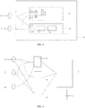
- FIG. 1 is a schematic diagram of function modules of an electrode multiplexing physiological parameter monitoring ring according to an embodiment of the present invention.
- the electrode multiplexing physiological parameter monitoring ring includes a microprocessor module 1, a built-in power supply 2, an electrocardiogram monitoring analog front end 3, a skin conductance monitoring module 4, a first electrode 6, and a second electrode 2.
- the microprocessor module 1 is connected to the electrocardiogram monitoring analog front end 3 and the skin conductance monitoring module 4.
- the first electrode 6 and the second electrode 7 are separately connected to the electrocardiogram monitoring analog front end 3.
- the electrocardiogram monitoring analog front end 3 processes electrocardiogram signals collected by the first electrode 6 and the second electrode 7.
- the first electrode 6 and the second electrode 7 are further separately connected to the skin conductance monitoring module 4.
- the skin conductance monitoring module 4 processes skin impendence signals collected by the first electrode 6 and the second electrode 7.
- a coupling manner in which the first electrode 6 and the second electrode 7 are coupled to the electrocardiogram monitoring analog front end 3 is direct current coupling or alternating current coupling, and is opposite to a coupling manner in which the first electrode 6 and the electrode 7 are coupled to the skin conductance monitoring module 4.
- the first electrode 6, the second electrode 7, and the electrocardiogram monitoring analog front end 3 constitute a single-lead electrocardiogram monitoring structure, to implement single-lead electrocardiogram monitoring and heart rate monitoring.
- the first electrode 6, the second electrode 7, and the skin conductance monitoring module 4 constitute a skin conductance monitoring structure to implement skin conductance monitoring.
- the first electrode 6 and the second electrode 7 are multiplexed, so that the physiological parameter monitoring ring of this embodiment of the present invention can implement electrocardiogram monitoring, heart rate monitoring, and skin conductance monitoring simultaneously with only two electrodes; and because the first electrode 6 and the second electrode 7 are separately coupled to the electrocardiogram monitoring front end 3 and the skin conductance monitoring module 4 in different coupling manners, the electrocardiogram monitoring, the heart rate monitoring, and the skin conductance monitoring will not interfere with each other.
- the physiological parameter monitoring ring in this embodiment of the present invention can reduce the number of electrodes, simplify system design, and implement device miniaturization.
- the microprocessor module 1 controls electrocardiogram monitoring and skin conductance monitoring, and receives and processes the signals from the electrocardiogram monitoring analog front end 3 and the skin conductance monitoring module 4.
- the microprocessor module 1 is connected to the electrocardiogram monitoring analog front end 3 through an SPI interface, an I2C interface, or an ADC interface.
- the microprocessor module 1 is connected to the skin conductance monitoring module 4 through an IO interface or the ADC interface.
- the built-in power supply 2 supplies power to constituent modules inside the ring according to the needs of the system design.
- the electrocardiogram monitoring analog front end 3 may be connected to the first electrode 6 and the second electrode 7 by direct current coupling, and processes (for example, amplifies or filters) the electrocardiogram signals collected by the first electrode 6 and the second electrode 7.
- the electrocardiogram monitoring analog front end 3 may be an AFE of ADS series of TI Company, or may be a product of ADI Company with similar functions.
- FIG. 2 is a schematic diagram of electrode distribution of an electrode multiplexing physiological parameter monitoring ring according to an embodiment of the present invention.
- the first electrode 6 and the second electrode 7 may be located on the same side of the ring.
- the first electrode 6 and the second electrode 7 are located on the inner side that is in contact with the skin.
- the first electrode 6 and the second electrode 7 can also be located in different sides of the ring.
- the first electrode 6 is located on the outer side of the ring
- the second electrode 7 is located on the inner side of the ring.
- the electrode multiplexing physiological parameter monitoring ring preferably includes a third electrode 8 which is connected to the electrocardiographic monitoring analog front end 3 by direct current coupling.
- the electrocardiogram monitoring analog front end 3 processes electrocardiographic signals collected by the electrode 6, the second electrode 7, and the third electrode 8, that is, the first electrode 6, the second electrode 7, and the third electrode 8, and the electrocardiographic monitoring analog front end 3 constitute a single-lead electrocardiogram monitoring structure to implement single-lead electrocardiogram monitoring and heart rate monitoring.
- the third electrode 8 may be located on the outer side of the ring.
- FIG. 3 is a schematic circuit diagram of a skin conductance monitoring module 4 of an electrode multiplexing physiological parameter monitoring ring according to an embodiment of the present invention.
- the skin conductance monitoring module 4 includes a signal excitation module 9 and a signal processing module 10.
- the signal excitation module 9 is used for generating a constant current source, and the signal processing module 10 is used for collecting and demodulating a received signal.
- the signal excitation module 9 generates an alternating current with a frequency greater than 32 kilohertz and amplitude lower than 100 microamperes.
- the alternating current generated by the signal excitation module 9 is square wave.
- the signal excitation module 9 includes a current source U1 for generating an alternating current, and the current source U1 is connected to the multiplexed electrode through a resistor-capacitor network.
- the current source U1 is connected to the first electrode 6 through a resistor R1 and a capacitor C1, and is connected to the second electrode 7 through a resistor R2 and a capacitor C2.
- the signal excitation module 9 is coupled to the body tissue through the first electrode 6 and the second electrode 7, so that alternating voltage signals with the same frequency are generated.
- the alternating voltage signals are collected and demodulated by the signal processing module 10 by alternating current coupling.
- the signals collected by the first electrode 6 and the second electrode 7 are inputted to a band-pass filter module 11 through two sampling capacitors C3 and C4 respectively, low-pass filtering is performed on the band-pass filtered signals by a low-pass filter 12, and the filtered signals are transmitted to the microprocessor module 1.
- the first electrode 6 and the first electrode 7 are used to generate an excitation signal as well as collect a signal, which reduces the number of electrodes for skin conductance monitoring to two.
- the electrocardiographic monitoring analog front end 3 is connected to the first electrode 6 and the second electrode 7 by direct current coupling
- the skin conductance monitoring module 4 is connected to the first electrode 6 and the second electrode 7 by alternating current coupling
- the electrocardiographic signal and the skin impedance signal collected by the first electrode 6 and the second electrode 7 will not interfere with each other.
- the electrocardiographic monitoring analog front end 3 may be connected to the first electrode 6 and the second electrode 7 by alternating current coupling
- the skin conductance monitoring module 4 may be connected to the first electrode 6 and the second electrode 7 by direct current coupling.
- FIG. 4 is a schematic diagram of another function module of an electrode multiplexing physiological parameter monitoring ring according to an embodiment of the present invention.
- the electrode multiplexing physiological parameter monitoring ring may further include a power supply management module 5 connected to the microprocessor module 1.
- the first electrode 6 and the second electrode 7 are separately connected to a built-in power supply 2 through the power supply management module 5.
- the power supply management module 5 is configured to: when the first electrode 6 and the second electrode 7 are in contact with the skin, from an open circuit between the first electrode 6 and the built-in power supply 2; and when the first electrode 6 and the second electrode 7 are connected to an external charger, form a closed-circuit between the first electrode 6 and the built-in power supply 2.
- the microprocessor module is configured to: when the closed-circuit is formed between the first electrode 6 and the built-in power supply 2, make the electrocardiogram monitoring analog front end 3 and the skin conductance monitoring module 4 stop working.
- the first electrode 6, the second electrode 7, the power supply management module 5, and the built-in power supply 2 constitute a charging structure, and the first electrode 6 and the second electrode 7 are used as charging interfaces to charge the built-in power supply 2.
- the physiological parameter monitoring ring can implement the electrocardiogram monitoring, the heart rate monitoring, the skin conductance monitoring, and a charging function by multiplexing the first electrode 6 and the second electrode 7, so that the number of electrodes can be further reduced, system design can be simplified, and the device can be further miniaturized.
- the physiological parameter monitoring function and the charging function of the physiological parameter monitoring ring can be automatically switched, so that system complexity is further reduced, and lower power consumption is implemented.
- the microprocessor module 1 may be connected to the power supply management module 5 through an IO interface.
- the power supply management module 5 includes resistors R3 and R4, a bias voltage Vbias of the system, and a voltage control switch K1.
- the bias voltage Vbias is connected to the first electrode 6 through the resistors R3 and R4.
- the Vbias voltage is greater than 2V and less than 3.3V
- the voltage control switch K1 is used for controlling the first electrode 6 to connect to a connection point of the resistors R3 and R4, or connect to one pole of the built-in power supply 2.
- the voltage difference between the body surface electrodes is at an mV level.
- the voltage on the first electrode 6 is smaller than the Vbias voltage
- the voltage control switch K1 connects the first electrode 6 and the connection point of the resistors R3 and R4, there is an open circuit between the first electrode 6 and the built-in power supply 2, and the built-in power supply 2 is not charged.
- the voltage control switch K1 connects the first electrode 6 to one pole of the built-in power supply 2, there is a closed-circuit between the first electrode 6 and the built-in power supply 2, and the built-in power supply 2 is charged.
- the microprocessor module 1 controls, by an analog switch, the power supply of the electrocardiogram monitoring analog front end 3 and the skin conductance monitoring module 4 to be turned off, so as to make the physiological parameter monitoring module stop working.
- the switching between the physiological parameter monitoring function and the charging function is automatically controlled by the voltage control switch K1, so that the built-in power supply is not charged when the physiological parameter detection is performed, and the physiological parameter monitoring is not performed when the built-in power supply is charged, and the two functions do not affect each other.
Landscapes
- Health & Medical Sciences (AREA)
- Life Sciences & Earth Sciences (AREA)
- Engineering & Computer Science (AREA)
- Animal Behavior & Ethology (AREA)
- Public Health (AREA)
- Pathology (AREA)
- Physics & Mathematics (AREA)
- Biomedical Technology (AREA)
- Heart & Thoracic Surgery (AREA)
- Medical Informatics (AREA)
- Molecular Biology (AREA)
- Surgery (AREA)
- Veterinary Medicine (AREA)
- General Health & Medical Sciences (AREA)
- Biophysics (AREA)
- Cardiology (AREA)
- Physiology (AREA)
- Signal Processing (AREA)
- Dermatology (AREA)
- Nuclear Medicine, Radiotherapy & Molecular Imaging (AREA)
- Radiology & Medical Imaging (AREA)
- Power Engineering (AREA)
- Artificial Intelligence (AREA)
- Computer Vision & Pattern Recognition (AREA)
- Psychiatry (AREA)
- Measurement And Recording Of Electrical Phenomena And Electrical Characteristics Of The Living Body (AREA)
Applications Claiming Priority (2)
| Application Number | Priority Date | Filing Date | Title |
|---|---|---|---|
| CN201810269936.2A CN110313906B (zh) | 2018-03-29 | 2018-03-29 | 一种电极复用生理参数监测指环 |
| PCT/CN2018/119855 WO2019184440A1 (fr) | 2018-03-29 | 2018-12-07 | Anneau de doigt de surveillance de paramètre physiologique multiplexé par électrode |
Publications (2)
| Publication Number | Publication Date |
|---|---|
| EP3763286A1 true EP3763286A1 (fr) | 2021-01-13 |
| EP3763286A4 EP3763286A4 (fr) | 2021-08-04 |
Family
ID=68062158
Family Applications (1)
| Application Number | Title | Priority Date | Filing Date |
|---|---|---|---|
| EP18912518.0A Withdrawn EP3763286A4 (fr) | 2018-03-29 | 2018-12-07 | Anneau de doigt de surveillance de paramètre physiologique multiplexé par électrode |
Country Status (5)
| Country | Link |
|---|---|
| US (1) | US11504018B2 (fr) |
| EP (1) | EP3763286A4 (fr) |
| CN (1) | CN110313906B (fr) |
| SG (1) | SG11201906112YA (fr) |
| WO (1) | WO2019184440A1 (fr) |
Families Citing this family (9)
| Publication number | Priority date | Publication date | Assignee | Title |
|---|---|---|---|---|
| CN112994694B (zh) * | 2021-02-08 | 2023-08-01 | 邹伦开 | 一种低功耗电子设备信号采集系统及方法 |
| CN113855035A (zh) * | 2021-09-29 | 2021-12-31 | 深圳芯森微电子有限公司 | 应用于穿戴健康电子的低功耗高精度生物电监测电路 |
| TWI797901B (zh) * | 2021-12-21 | 2023-04-01 | 財團法人工業技術研究院 | 電生理訊號量測系統、電生理訊號調節方法與電極組件 |
| CN116671924A (zh) * | 2022-02-22 | 2023-09-01 | 广州视源电子科技股份有限公司 | 一种多功能电路以及心电检测设备 |
| CN114305357A (zh) * | 2022-03-07 | 2022-04-12 | 广东玖智科技有限公司 | 健康监护系统及多功能智能戒指 |
| EP4470458A1 (fr) * | 2023-05-30 | 2024-12-04 | Withings | Décharge d'électrode sur un dispositif de mesure |
| CN116844392B (zh) * | 2023-06-09 | 2026-01-30 | 华能山东发电有限公司烟台发电厂 | 一种教学用和巡检用的巡检设备 |
| CN117281478B (zh) * | 2023-10-17 | 2024-05-28 | 天津大学 | 一种皮肤病辅助诊断装置及系统 |
| USD1097835S1 (en) * | 2024-04-18 | 2025-10-14 | Senbiosys | Personal monitoring device |
Family Cites Families (13)
| Publication number | Priority date | Publication date | Assignee | Title |
|---|---|---|---|---|
| CN100518630C (zh) * | 2004-05-08 | 2009-07-29 | 香港中文大学 | 指环式生理信息监测装置 |
| KR101042827B1 (ko) * | 2008-10-16 | 2011-06-20 | 연세대학교 산학협력단 | 마우스형 다중 생체신호 측정장치 |
| WO2013038285A1 (fr) | 2011-09-15 | 2013-03-21 | Koninklijke Philips Electronics N.V. | Système d'eeg et système de régulation de pression d'électrode |
| CN102499636B (zh) | 2011-09-23 | 2013-07-31 | 东莞广州中医药大学中医药数理工程研究院 | 一种掌上型医用多道生物信息采集移动终端系统 |
| EP2591720B1 (fr) * | 2011-11-08 | 2016-04-06 | Imec | Système d'acquisition biomédicale avec réduction d'artéfacts de mouvement |
| CN103908241B (zh) | 2012-12-31 | 2016-03-02 | 中国移动通信集团公司 | 睡眠及呼吸检测方法、装置 |
| CN105232034A (zh) * | 2014-06-04 | 2016-01-13 | 中国科学院半导体研究所 | 用于心电信号及人体阻抗检测的电极与电路复用结构 |
| WO2015196298A1 (fr) * | 2014-06-26 | 2015-12-30 | Biopeak Corporation | Système de capteur à paramètres multiples pour mesurer des signaux physiologiques |
| CN113331813B (zh) | 2015-01-08 | 2024-06-11 | 美达森斯生物测定有限公司 | 用于生理监测的电极阵列和包括或利用电极阵列的设备 |
| WO2016123206A1 (fr) * | 2015-01-27 | 2016-08-04 | Medicomp, Inc. | Systèmes et procédés pour traitement de signal amélioré à l'aide de dispositifs de surveillance d'électrocardiogramme d'anneau porté au doigt |
| US9685802B1 (en) * | 2015-04-29 | 2017-06-20 | Verily Life Sciences, LLC | Detection of accessory presence and orientation |
| CN207150557U (zh) | 2017-07-18 | 2018-03-27 | 潍坊歌尔电子有限公司 | 一种电极复用电路及设有该电路的智能腕戴设备 |
| CN208573734U (zh) * | 2018-03-29 | 2019-03-05 | 杭州兆观传感科技有限公司 | 一种电极复用生理参数监测指环 |
-
2018
- 2018-03-29 CN CN201810269936.2A patent/CN110313906B/zh active Active
- 2018-12-07 SG SG11201906112Y patent/SG11201906112YA/en unknown
- 2018-12-07 WO PCT/CN2018/119855 patent/WO2019184440A1/fr not_active Ceased
- 2018-12-07 EP EP18912518.0A patent/EP3763286A4/fr not_active Withdrawn
- 2018-12-07 US US16/613,581 patent/US11504018B2/en active Active
Also Published As
| Publication number | Publication date |
|---|---|
| EP3763286A4 (fr) | 2021-08-04 |
| CN110313906B (zh) | 2024-09-27 |
| US20210321893A1 (en) | 2021-10-21 |
| WO2019184440A1 (fr) | 2019-10-03 |
| US11504018B2 (en) | 2022-11-22 |
| CN110313906A (zh) | 2019-10-11 |
| SG11201906112YA (en) | 2019-11-28 |
Similar Documents
| Publication | Publication Date | Title |
|---|---|---|
| US11504018B2 (en) | Electrode multiplexed physiological parameter monitoring finger ring | |
| CN208573734U (zh) | 一种电极复用生理参数监测指环 | |
| CN104490387B (zh) | 能够抑制运动干扰的无线便携与穿戴式心电检测器 | |
| CN104622460B (zh) | 一种ecg信号采集装置 | |
| CN103405228B (zh) | 一种便携式心电及表面肌电测量装置 | |
| CN101159086B (zh) | 基于脑电信息检波的呼叫装置 | |
| CN104665825B (zh) | 一种便携式低功耗三导联心电智能监护系统 | |
| CN106214147A (zh) | 一种可穿戴监护装置 | |
| CN105496400A (zh) | 便捷式多导联无线心电监测设备及方法 | |
| CN102894973B (zh) | 脑电信号放大器 | |
| CN106361326A (zh) | 脑电波采集及传输的终端 | |
| CN105852839A (zh) | 一种基于生物电阻抗技术的心率测量方法及装置 | |
| CN105266795A (zh) | 动态心电信号采集装置 | |
| CN105997066A (zh) | 一种便携式人体表面肌电信号采集系统 | |
| CN104287728A (zh) | 采用光纤传输的有源表面肌电检测探头 | |
| Ai et al. | Low-power wireless wearable ECG monitoring chestbelt based on ferroelectric microprocessor | |
| CN105287067A (zh) | 一种针对渐冻症患者的智能家居系统 | |
| CN207545070U (zh) | 一种动态心电信号快速恢复电路 | |
| CN205386149U (zh) | 一种集成的便携式心电与皮电监测仪 | |
| CN204542121U (zh) | 一种便携式手指双电极心电信号采集装置 | |
| CN209733988U (zh) | 一种集成心电监测和自动除颤功能的胸骨固定带 | |
| KR102236976B1 (ko) | 탁상형 심전도 측정 시스템 | |
| CN208048720U (zh) | 一种高海拔地区人体生理参数监测预警可穿戴设备 | |
| Liu et al. | A wearable ECG apperatus for ubiquitous health care | |
| CN218165273U (zh) | 信号采集装置及肌电采集仪 |
Legal Events
| Date | Code | Title | Description |
|---|---|---|---|
| STAA | Information on the status of an ep patent application or granted ep patent |
Free format text: STATUS: THE INTERNATIONAL PUBLICATION HAS BEEN MADE |
|
| PUAI | Public reference made under article 153(3) epc to a published international application that has entered the european phase |
Free format text: ORIGINAL CODE: 0009012 |
|
| STAA | Information on the status of an ep patent application or granted ep patent |
Free format text: STATUS: REQUEST FOR EXAMINATION WAS MADE |
|
| 17P | Request for examination filed |
Effective date: 20201008 |
|
| AK | Designated contracting states |
Kind code of ref document: A1 Designated state(s): AL AT BE BG CH CY CZ DE DK EE ES FI FR GB GR HR HU IE IS IT LI LT LU LV MC MK MT NL NO PL PT RO RS SE SI SK SM TR |
|
| AX | Request for extension of the european patent |
Extension state: BA ME |
|
| REG | Reference to a national code |
Ref country code: DE Ref legal event code: R079 Free format text: PREVIOUS MAIN CLASS: A61B0005040200 Ipc: A61B0005053000 |
|
| DAV | Request for validation of the european patent (deleted) | ||
| DAX | Request for extension of the european patent (deleted) | ||
| A4 | Supplementary search report drawn up and despatched |
Effective date: 20210706 |
|
| RIC1 | Information provided on ipc code assigned before grant |
Ipc: A61B 5/053 20210101AFI20210630BHEP Ipc: A61B 5/024 20060101ALI20210630BHEP Ipc: A61B 5/271 20210101ALI20210630BHEP Ipc: A61B 5/00 20060101ALI20210630BHEP |
|
| 19U | Interruption of proceedings before grant |
Effective date: 20220225 |
|
| 19X | Information on stay/interruption of proceedings deleted |
Effective date: 20220520 |
|
| STAA | Information on the status of an ep patent application or granted ep patent |
Free format text: STATUS: THE APPLICATION IS DEEMED TO BE WITHDRAWN |
|
| 18D | Application deemed to be withdrawn |
Effective date: 20240702 |