EP3763337B1 - Dorn mit positionierungsmarkierung - Google Patents
Dorn mit positionierungsmarkierung Download PDFInfo
- Publication number
- EP3763337B1 EP3763337B1 EP19184899.3A EP19184899A EP3763337B1 EP 3763337 B1 EP3763337 B1 EP 3763337B1 EP 19184899 A EP19184899 A EP 19184899A EP 3763337 B1 EP3763337 B1 EP 3763337B1
- Authority
- EP
- European Patent Office
- Prior art keywords
- mandrel
- implant
- positioning mark
- cartilage
- recess
- Prior art date
- Legal status (The legal status is an assumption and is not a legal conclusion. Google has not performed a legal analysis and makes no representation as to the accuracy of the status listed.)
- Active
Links
Images


Classifications
-
- A—HUMAN NECESSITIES
- A61—MEDICAL OR VETERINARY SCIENCE; HYGIENE
- A61F—FILTERS IMPLANTABLE INTO BLOOD VESSELS; PROSTHESES; DEVICES PROVIDING PATENCY TO, OR PREVENTING COLLAPSING OF, TUBULAR STRUCTURES OF THE BODY, e.g. STENTS; ORTHOPAEDIC, NURSING OR CONTRACEPTIVE DEVICES; FOMENTATION; TREATMENT OR PROTECTION OF EYES OR EARS; BANDAGES, DRESSINGS OR ABSORBENT PADS; FIRST-AID KITS
- A61F2/00—Filters implantable into blood vessels; Prostheses, i.e. artificial substitutes or replacements for parts of the body; Appliances for connecting them with the body; Devices providing patency to, or preventing collapsing of, tubular structures of the body, e.g. stents
- A61F2/02—Prostheses implantable into the body
- A61F2/30—Joints
- A61F2/46—Special tools for implanting artificial joints
- A61F2/4603—Special tools for implanting artificial joints for insertion or extraction of endoprosthetic joints or of accessories thereof
- A61F2/4618—Special tools for implanting artificial joints for insertion or extraction of endoprosthetic joints or of accessories thereof of cartilage
-
- A—HUMAN NECESSITIES
- A61—MEDICAL OR VETERINARY SCIENCE; HYGIENE
- A61B—DIAGNOSIS; SURGERY; IDENTIFICATION
- A61B17/00—Surgical instruments, devices or methods
- A61B17/16—Instruments for performing osteoclasis; Drills or chisels for bones; Trepans
- A61B17/17—Guides or aligning means for drills, mills, pins or wires
- A61B17/1739—Guides or aligning means for drills, mills, pins or wires specially adapted for particular parts of the body
- A61B17/1764—Guides or aligning means for drills, mills, pins or wires specially adapted for particular parts of the body for the knee
-
- A—HUMAN NECESSITIES
- A61—MEDICAL OR VETERINARY SCIENCE; HYGIENE
- A61F—FILTERS IMPLANTABLE INTO BLOOD VESSELS; PROSTHESES; DEVICES PROVIDING PATENCY TO, OR PREVENTING COLLAPSING OF, TUBULAR STRUCTURES OF THE BODY, e.g. STENTS; ORTHOPAEDIC, NURSING OR CONTRACEPTIVE DEVICES; FOMENTATION; TREATMENT OR PROTECTION OF EYES OR EARS; BANDAGES, DRESSINGS OR ABSORBENT PADS; FIRST-AID KITS
- A61F2/00—Filters implantable into blood vessels; Prostheses, i.e. artificial substitutes or replacements for parts of the body; Appliances for connecting them with the body; Devices providing patency to, or preventing collapsing of, tubular structures of the body, e.g. stents
- A61F2/02—Prostheses implantable into the body
- A61F2/30—Joints
- A61F2/30756—Cartilage endoprostheses
-
- A—HUMAN NECESSITIES
- A61—MEDICAL OR VETERINARY SCIENCE; HYGIENE
- A61F—FILTERS IMPLANTABLE INTO BLOOD VESSELS; PROSTHESES; DEVICES PROVIDING PATENCY TO, OR PREVENTING COLLAPSING OF, TUBULAR STRUCTURES OF THE BODY, e.g. STENTS; ORTHOPAEDIC, NURSING OR CONTRACEPTIVE DEVICES; FOMENTATION; TREATMENT OR PROTECTION OF EYES OR EARS; BANDAGES, DRESSINGS OR ABSORBENT PADS; FIRST-AID KITS
- A61F2/00—Filters implantable into blood vessels; Prostheses, i.e. artificial substitutes or replacements for parts of the body; Appliances for connecting them with the body; Devices providing patency to, or preventing collapsing of, tubular structures of the body, e.g. stents
- A61F2/02—Prostheses implantable into the body
- A61F2/30—Joints
- A61F2/46—Special tools for implanting artificial joints
- A61F2/4684—Trial or dummy prostheses
-
- A—HUMAN NECESSITIES
- A61—MEDICAL OR VETERINARY SCIENCE; HYGIENE
- A61B—DIAGNOSIS; SURGERY; IDENTIFICATION
- A61B17/00—Surgical instruments, devices or methods
- A61B17/56—Surgical instruments or methods for treatment of bones or joints; Devices specially adapted therefor
- A61B2017/568—Surgical instruments or methods for treatment of bones or joints; Devices specially adapted therefor produced with shape and dimensions specific for an individual patient
-
- A—HUMAN NECESSITIES
- A61—MEDICAL OR VETERINARY SCIENCE; HYGIENE
- A61F—FILTERS IMPLANTABLE INTO BLOOD VESSELS; PROSTHESES; DEVICES PROVIDING PATENCY TO, OR PREVENTING COLLAPSING OF, TUBULAR STRUCTURES OF THE BODY, e.g. STENTS; ORTHOPAEDIC, NURSING OR CONTRACEPTIVE DEVICES; FOMENTATION; TREATMENT OR PROTECTION OF EYES OR EARS; BANDAGES, DRESSINGS OR ABSORBENT PADS; FIRST-AID KITS
- A61F2/00—Filters implantable into blood vessels; Prostheses, i.e. artificial substitutes or replacements for parts of the body; Appliances for connecting them with the body; Devices providing patency to, or preventing collapsing of, tubular structures of the body, e.g. stents
- A61F2/02—Prostheses implantable into the body
- A61F2/30—Joints
- A61F2/30756—Cartilage endoprostheses
- A61F2002/30759—Mosaicplasty, i.e. using a plurality of individual cartilage plugs for filling a substantial cartilage defect
-
- A—HUMAN NECESSITIES
- A61—MEDICAL OR VETERINARY SCIENCE; HYGIENE
- A61F—FILTERS IMPLANTABLE INTO BLOOD VESSELS; PROSTHESES; DEVICES PROVIDING PATENCY TO, OR PREVENTING COLLAPSING OF, TUBULAR STRUCTURES OF THE BODY, e.g. STENTS; ORTHOPAEDIC, NURSING OR CONTRACEPTIVE DEVICES; FOMENTATION; TREATMENT OR PROTECTION OF EYES OR EARS; BANDAGES, DRESSINGS OR ABSORBENT PADS; FIRST-AID KITS
- A61F2/00—Filters implantable into blood vessels; Prostheses, i.e. artificial substitutes or replacements for parts of the body; Appliances for connecting them with the body; Devices providing patency to, or preventing collapsing of, tubular structures of the body, e.g. stents
- A61F2/02—Prostheses implantable into the body
- A61F2/30—Joints
- A61F2/3094—Designing or manufacturing processes
- A61F2/30942—Designing or manufacturing processes for designing or making customized prostheses, e.g. using templates, CT or NMR scans, finite-element analysis or CAD-CAM techniques
- A61F2002/30948—Designing or manufacturing processes for designing or making customized prostheses, e.g. using templates, CT or NMR scans, finite-element analysis or CAD-CAM techniques using computerized tomography, i.e. CT scans
-
- A—HUMAN NECESSITIES
- A61—MEDICAL OR VETERINARY SCIENCE; HYGIENE
- A61F—FILTERS IMPLANTABLE INTO BLOOD VESSELS; PROSTHESES; DEVICES PROVIDING PATENCY TO, OR PREVENTING COLLAPSING OF, TUBULAR STRUCTURES OF THE BODY, e.g. STENTS; ORTHOPAEDIC, NURSING OR CONTRACEPTIVE DEVICES; FOMENTATION; TREATMENT OR PROTECTION OF EYES OR EARS; BANDAGES, DRESSINGS OR ABSORBENT PADS; FIRST-AID KITS
- A61F2/00—Filters implantable into blood vessels; Prostheses, i.e. artificial substitutes or replacements for parts of the body; Appliances for connecting them with the body; Devices providing patency to, or preventing collapsing of, tubular structures of the body, e.g. stents
- A61F2/02—Prostheses implantable into the body
- A61F2/30—Joints
- A61F2/46—Special tools for implanting artificial joints
- A61F2002/4687—Mechanical guides for implantation instruments
Definitions
- This present invention relates generally to the field of designing tools for use during replacement of damaged cartilage in an articulate surface in a joint.
- the present invention also relates to tools such as mandrels for rotationally positioning and inserting a medical implant in a recess made in a joint using a mandrel for hammering, pressing and/or pushing the implant into the recess.
- the closest prior art is document US 2016/199198 A1 , which defines the preamble of claim 1.
- Pain and overuse disorders of the joints in the body is a common problem.
- the weight-bearing and articulate surfaces of the knees and other joints are covered with a layer of soft tissue that typically comprises a significant amount of hyaline cartilage.
- the friction between the cartilage and the surrounding parts of the joint is very low, which facilitates movement of the joints under high pressure.
- the cartilage is however prone to damage due to disease, injury or chronic wear.
- it does not readily heal after damages, as opposed to other connective tissue, and if healed the durable hyaline cartilage is often replaced by less durable fibrocartilage. This means that damages of the cartilage gradually become worse.
- injury/disease comes a problem with pain which results in handicap and loss of function. It is therefore important to have efficient means and methods for repairing damaged cartilage in knee joints.
- Another example is the case that the implant is placed in a too shallow position, which may result in a too high top of the implant that causes the joint to articulate in an uneven manner and increase the load on an opposing point of the joint.
- the implant is placed in a too shallow position, which may result in a too high top of the implant that causes the joint to articulate in an uneven manner and increase the load on an opposing point of the joint.
- small misplacements or deviations from an ideal position may result in pain, longer time for convalescence or even a surgical operation being done in vain and making it more difficult to repair the damage in the joint.
- a large burden is therefore placed on the surgeon not to misplace or misfit the implant. There is therefore a need for tools that are designed to relieve and support the surgeon in the implant surgery.
- the design of the implant and the surgical tools is crucial for the outcome of the implant's life-time in a joint.
- the parameters for designing are of uttermost importance for the result in these operations. Small differences in the design can make a huge difference in fit and life-time of an implant in the body, convalescence time for the patient, economic values due or surgery time, and success of operations. Also, the number of successful operations will increase, and the working conditions for the surgeon will be improved, if the designing parameters are selected right.
- EP2389905 A1 shows a design method for designing an individually designed surgical kit.
- the general object of the invention is to solve the problem of designing an improved surgical kit for use during cartilage repair for replacing damaged cartilage and also an improved design method for designing a mandrel for hammering, pressing and/or pushing an implant into a recess made in a joint.
- the object of the invention is to design a mandrel which makes the surgical operation more accurate and safer, and which provides for less surgeon dependent operation procedures and faster recovery of the patients after surgery.
- the object of the invention is to design a mandrel for an implant which make the surgical operation safer and results in better fitting implants, less surgeon dependent operation procedures and faster recovery of the patients after surgery. It is a further object of the invention to provide a solution for making the surgical operation of rotationally positioning and inserting an implant in a recess safer and more accurate by providing a mandrel with at least one element and/or positioning mark which is adapted for rotationally positioning the mandrel in relation to at least one of an anatomic dependent direction, at least one element and/or positioning mark of the implant, and a mark to be made on side of a recess to be made at the determined implant position.
- a method for designing a mandrel according to the invention is defined in claim 1.
- the method further comprises determining the position of the at least one element and/or positioning mark of the mandrel so that said at least one element and/or positioning mark is adapted for rotational positioning of the mandrel in relation to an element and/or a positioning mark of the implant. This enables a very exact positioning of the mandrel onto the implant to be implanted.
- the method further comprises determining the position of the at least one element and/or positioning mark of the mandrel so that said at least one element and/or positioning mark is adapted for rotational positioning of the mandrel in relation to a mark on the side of the recess where the implant is to be inserted.
- the method further comprises determining the position of the at least one element and/or positioning mark of the mandrel so that said at least one element and/or positioning mark is adapted for rotational positioning of the mandrel in relation to an anatomic dependent direction.
- the method further comprises forming the contacting surface of the mandrel into a substantially circular shape, and designing the at least one element and/or positioning mark as a marking, such as e.g. a dot, or a groove in the circumference of the substantially circular shape.
- the method further comprises forming the contacting surface of the mandrel from at least two substantially circular shapes, such that each of said substantially circular shapes is partly overlapping at least one other substantially circular shape, and designing the at least one element and/or positioning mark as a marking, such as e.g. a dot, or a groove in the circumference of at least one of said at least two substantially circular shapes.
- the method further comprises designing at least a portion of the contacting surface of the mandrel to have an inverted surface, or essentially inverted surface, to the articulate surface of the implant to be inserted in the recess using the mandrel.
- the method further comprises receiving image data representing a three-dimensional image of a joint; identifying cartilage damage in the image data; determining the position for the implant to be used for cartilage repair; simulating a healthy surface of the area of damaged cartilage; and designing the articulate surface of the implant to match the simulated healthy surface.
- the method further comprises simulating said healthy surface based on image data representing a three-dimensional image of a joint and the curvature of the cartilage immediately surrounding the area of damaged cartilage.
- the method further comprises designing the mandrel with a grip portion that has a smaller diameter close to the contacting surface than at the middle of the grip portion. It is an advantage to design the mandrel so that the point of gravity lies in the hand of the surgeon using the mandrel rather than close to the contacting surface. Further, if the grip portion has a larger diameter towards the middle, it may lie better in the hand of the surgeon.
- a mandrel according to the invention is defined in claim 11.
- the at least one element and/or positioning mark of the mandrel is adapted for rotational positioning of the mandrel in relation to at least one of at least one element and/or positioning mark on the surface of the implant, a mark on the side of the recess where the implant is to be inserted, and an anatomic dependent direction.
- the contacting surface of the mandrel has a substantially circular shape
- the at least one element and/or positioning mark is a marking, such as e.g. a dot, or a groove in the circumference of the substantially circular shape.
- the contacting surface of the mandrel is formed from at least two substantially circular shapes, such that each of said substantially circular shapes is partly overlapping at least one other substantially circular shape, and the at least one element and/or positioning mark is a marking, such as e.g. a dot, or a groove in the circumference of at least one of said at least two substantially circular shapes.
- At least a portion of the contacting surface of the mandrel has an inverted surface, or essentially inverted surface, to the articulate surface of the implant to be inserted into the recess using the mandrel.
- the contacting surface of the mandrel has a cross-sectional profile that is designed to correspond to the cross-sectional profile of the implant to be inserted into the recess using the mandrel, with a tolerance preventing the mandrel from coming into contact with the surrounding cartilage during insertion of the implant into the recess.
- the mandrel further comprises a grip portion that has a smaller diameter close to the contacting surface than at the middle of the grip portion. It is an advantage to design the mandrel so that the point of gravity lies in the hand of the surgeon using the mandrel rather than close to the contacting surface. Further, if the grip portion has a larger diameter towards the middle, it may lie better in the hand of the surgeon.
- the technology disclosed relates to a design method for designing a mandrel for hammering, pressing and/or pushing an implant into position in a recess made in a joint and firmly attach the implant to the bone of a patient, comprising determining a contacting surface of the mandrel to be in contact with the articulate surface of the implant during the insertion of the implant to fit the articulate surface of the implant in that the contacting surface of the mandrel has a corresponding cross-sectional profile.
- the implant which is hammered/pressed into a recess using the mandrel is an individually customized implant designed with an articulate surface having a shape and curvature which is simulating a healthy surface of the area of damaged cartilage at the determined implant position where the implant is to be inserted.
- the contacting surface of the mandrel to be in contact with the articulate surface of the implant (which is to be inserted into a joint using the mandrel) is then designed to have an inverted surface curvature to the surface curvature of the articulate surface of the implant.
- a mandrel may according to the invention be any type of tool that may be used for tapping, hammering, pressing and/or pushing an implant into position into a recess made in a joint of a patient.
- the technology disclosed relates to a design method for designing a mandrel for hammering, pressing and/or pushing an implant into position in a recess made in a joint and firmly attaching the implant to the bone of a patient, comprising determining a surface of the mandrel to be in contact with the articulate surface of the implant during the insertion of the implant to fit the articulate surface of the implant in that the contacting surface of the mandrel has a corresponding cross-sectional profile.
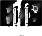
- Figure 1 shows an example of a surgical kit.
- This particular example of a surgical kit is especially adapted for cartilage replacement at the femur of a knee joint.
- the invention may however be applied for cartilage replacement in an articulate surface in any other joint in the body, e.g. elbow, ankle, finger, hip, toe and shoulder.
- the surgical kit may e.g. comprise a height adjustment device 16, a hammer tool/mandrel 35, a drill-bit or reamer-bit 8, an implant dummy 36, a guide tool 12, and an implant 10.
- a surgical kit may additionally comprise e.g. a cartilage cutting tool or cartilage cutter, a cartilage cut drill, a punch, a reamer guide, and/or a drill guide.
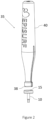
- Figures 2-4 show different embodiments of a mandrel 35 according to the invention having a grip portion 40 and a contacting surface 38 designed to be in contact with an articulate surface 15 of an implant 10 during insertion of the implant 10 by hammering, pressing and/or pushing the implant 10 into position in a recess made in a joint.
- the contacting surface 38 of the mandrel 35 is designed to have an inverted surface to the articulate surface 15 of the implant 10 to be implanted.
- the mandrel 35 preferably comprises an element and/or a positioning mark 37 for rotational positioning of the mandrel 35 in the recess.
- the element and/or positioning mark 37 is preferably arranged to allow the simultaneous rotational positioning of the implant 10 in the recess.
- the contacting surface 38 of the mandrel 35 is preferably the same size, or slightly smaller than, the surface 15 of the implant 10 to be implanted. If the contacting surface 38 of the mandrel 35 has a cross-sectional profile that has a tolerance with respect to the cross-sectional profile of the implant 10 to be inserted into the recess using the mandrel 35, this may prevent the mandrel 35 from coming into contact with the surrounding cartilage during insertion of the implant 10 into the recess.
- the diameter of the surface 38 may be larger or smaller than the diameter of the grip portion 40 of the mandrel 35.
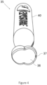
- the mandrel 35 shown in figure 4 is intended for use with an implant 10 formed from two substantially circular shapes such that each of said substantially circular shapes is partly overlapping the other substantially circular shape.
- the mandrel 35 shown in figures 2-4 further comprises a grip portion 40, which is intended to provide a good grip for the surgeon using the mandrel 35.
- the grip portion 40 is preferably shaped to be thicker in the middle, and have a smaller diameter close to the contacting surface 38 than at the middle of the grip portion 40. It is an advantage to design the mandrel so that the point of gravity lies in the hand of the surgeon using the mandrel 35 rather than close to the contacting surface 38. Further, if the grip portion 40 has a larger diameter towards the middle, it may lie better in the hand of the surgeon.
- Figure 5a shows an example of a medical implant 10 provided with a positioning mark 11.
- the plate shaped implant body has an articulate surface (first surface) 15 configured to face the articulating part of the joint and a bone contact surface (second surface) configured to face bone structure in the joint.
- the plate shaped implant body has a cross-section that substantially corresponds to the area of the damaged cartilage and the articulate surface 15 has a curvature that substantially corresponds to the curvature of a healthy articulate surface at the site of diseased cartilage.
- the extending post extends from the bone contact surface. Since the implant 10 of the inventive concept is custom made for a specific patient, figure 5a is an exemplifying schematic picture displaying an embodiment of the implant 10. Between the articulate surface 15 and the bone contact surface there is a cartilage contacting surface.
- the implant is specially designed, depending on the knees appearance and the shape of the damage and in order to resemble the body's own parts, having a surface which preferably corresponds to a three dimensional (3D) image of a simulated healthy cartilage surface.
- the implant will be tailor-made to fit each patient's damaged part of the joint.
- the implant body is substantially plate shaped, meaning that the shortest distance crossing the surface 15 of the implant body is substantially larger, e.g. at least 1.5 times larger than the thickness of the implant body.
- substantially plate shaped is meant that the implant body may be substantially flat or may have some curvature, preferably a 3D curvature of the articulate surface 15.
- the articulate surface 15 may for example have a curvature that corresponds to a simulated healthy cartilage reconstructed from an image taken e.g. with MRI or CT-scanning of the damaged cartilage surface of the joint.
- the area and the shape of the implant surface 15 are individual depending on the size of cartilage damage and location of the cartilage damage.
- the area and shape of the implant can be decided by the surgeon himself or be chosen from predetermined shapes.
- the cross-section of the implant body may have a circular or roughly circular, oval, triangular, square or irregular shape, preferably a shape without sharp edges.
- small implants are preferred since they have a smaller impact on the joint at the site of incision and are also more easily implanted using arthroscopy or smaller open surgical procedures.
- the primary factor for determining the size of the implant is however the nature of the lesion to be repaired.
- the implant replaces an area of damaged cartilage in an articulate surface of a joint.
- the damaged cartilage is removed and also a part of the bone beneath, i.e. a recess fitting the implant is made in the bone.
- the recess can e.g. be drilled in the bone to fit the implant structure.
- the extending post or rod-part of the implant 10 is used for securing the implant 10 in the drilled hole of the bone.
- the length of the extending post, extending from the implant head, is adjusted to a length needed to secure the implant 10 in the bone.
- the extending post is intended to give a primary fixation of the implant 10. It provides mechanical attachment of the implant 10 to the bone in immediate connection with the surgical operation.
- Figure 5b shows another example of a medical implant 10, where the implant 10 comprises two substantially circular shapes 18, where one of the circular shapes 18 is provided with a positioning mark 11 on its articulate surface 15.
- the positioning mark 11 on the articulate surface 15, i.e. the top surface 15 facing the articulating part of the joint, of the medical implant 10 illustrated in figures 5a-b is designed to be used for determining the orientation in which the implant 10 is to be placed in a recess made in a damaged articulate surface of a joint.
- the positioning mark 11 may be designed so that the direction of the positioning mark 11 is determining the placement orientation of the implant 10 in a recess, in that the placement orientation of the positioning mark 11 is also to be indicated by a mark made on the side of a recess made in the articulate surface of a joint in which the implant 10 is to be inserted, thereby providing for a correct or more accurate orientation of the implant when inserted in the recess made in a damaged articulate surface of a joint.
- the positioning mark 11 on the articulate surface 15, i.e. the top surface 15 facing the articulating part of the joint, of the implant 10 may be designed so that the direction of the positioning mark 11 is designed to be pointing in an anatomic dependent direction in relation to a recess made in the articulate surface of a joint in which the implant 10 is to be inserted, thereby providing for a correct or more accurate orientation of the implant 10 when inserted in the recess made in a damaged articulate surface of a joint.
- FIG. 6 shows a guide tool 12 which may be used with embodiments of the invention.
- the guide tool 12 preferably has a cartilage contact surface that has a shape and contour that is designed to correspond to and to fit the contour of the cartilage or the subchondral bone in the joint in a predetermined area surrounding the site of diseased cartilage.
- the guide tool 12 aids with exact precision removal of a volume of cartilage and subchondral bone, and preferably has a guide channel 54.
- the guide tool 12 preferably comprises a positioning mark 50, comprised in the structure of the guide tool 12, wherein the positioning mark 50 is aligned with the centre of the guide channel 54 in a joint axis direction.
- the guide tool 12 may also comprise an indentation 51 that enables marking of the cartilage surface in the position of the positioning mark 50.
- Figure 7 shows a guide tool 12 comprising an implant dummy 36 placed inside the guide channel 54 of the guide tool 12.
- the guide tool 12 may be placed in the joint using pins 41 for stabilization and fastening.
- the guide channel 54 is used for stabilizing tools that are to be inserted into the guide channel 54, such as e.g. a drill bit 8 and/or an implant dummy 36.
- the guide channel 54 therefore preferably has an inner cross-sectional profile that is designed to correspond to the cross-section of the drill bit 8 and/or the implant dummy 36.
- the drill bit 8 and/or the implant dummy 36 fits the guide channel 54, with a slight tolerance to allow a sliding movement of the drill bit 8 and/or the implant dummy 36 in the guide channel 54.
- the guide channel 54 has an opening on the cartilage contact surface, arranged to be placed in a position corresponding to the site of the diseased cartilage in a joint.
- the height of the guide channel 54 must be sufficiently long to give support to the tools used inside the guide channel 54.
- the height of the guide channel 54 may e.g. be between 1 and 10 cm, preferably 3-10 cm, and always sufficiently high to ensure stabilization of the tools that are to be inserted into the guide channel 54.
- the top of the guide channel 54 is designed to project above the tissue surrounding the surgery cut when the guide tool is placed on the cartilage in a joint during surgery.
- the guide tool 12 is easy to place due to the precise fit of the cartilage contact surface on the cartilage surface.
- the size and shape of cartilage contact surface of the guide tool 12 is determined depending on the size and shape of the damaged cartilage and thus on the cross section of the implant body 10, and also depending on the position of the cartilage area in a joint.
- the size, shape or spread of the cartilage contact surface of the guide tool 12 is a consideration between the following aspects; minimize surgery lesion, maximize stability for guide tool 12, anatomic limitations on the site of the injury. Not all cartilage surfaces in a joint can be used for placement of the guide tool 12. A large spread of the cartilage contact surface is preferable to get good stability of the guide tool 12, however, a large surface area of the surface may also lead to a large surgical intervention which is undesired.
- the size of the guide tool 12 is determined by a balance between the desire to achieve good positioning stability and small surgical operations.
- the cartilage contact surface need not have a continuous, regular shape, but may have an irregular shape, as long as it gives adequate support and stable positioning of the guide tool 12.
- the cartilage contact surface may also consist of three separated points.
- Figure 8 shows the use of a mandrel 35 for for hammering, pressing and/or pushing an implant 10 into position in a recess made in a joint, according to one or more embodiments of the invention.
- Figure 8 also shows a positioning mark indicated on the cartilage surface.
- the positioning mark is preferably added to the cartilage surface when the guide tool 12 is placed in the joint, e.g. by inserting a marking pen into the indentation 51 in the guide tool 12.
- the implant 10 is placed in the recess, rotated so that the positioning mark 11 of the implant 10 corresponds to the positioning mark indicated on the cartilage surface.
- the element and/or positioning mark 37 on the mandrel 35 is then preferably aligned with the positioning mark 11 on the implant 10 and the positioning mark indicated on the cartilage surface.
- the element and/or a positioning mark 37 on the mandrel 35 is preferably designed to allow the surgeon to view the the positioning mark 11 of the implant 10 when the mandrel 35 is used for hammering, pressing and/or pushing the implant 10 into position in a recess.
- the method for inserting an implant 10 into a recess by use of a mandrel 35 further comprises: providing a guide tool 12 comprising a positioning feature/mark 50; and making, by one of a surgeon and a mechanical arm such as a robot arm, a mark on the side of a recess made in an articulate surface of the joint in the direction of the positioning mark of said guide tool 12, thereby determining the future placement orientation of the implant 10.
- the surgical kit may also comprise a height adjustment device 16, e.g. comprising a male part 47 and a female receiving part 48 which when used together allows for stepwise adjustment of drill depth.
- the male part 47 is in the outermost position in a zero-mode and may from there be adjusted inwards allowing the surgeon to for example make stepwise deeper drill holes.
- the height adjustment device 16 is in starting mode or outermost zero-mode, the position marking of the guide tool 12 and the positioning marking of the height adjustment device 16 are aligned.
- the surgeon is also able to adjust the depth of drilling and cutting into the bone.
- the length of the guide channel 54 may be varied since the guide tool 12 and the height adjustment device 16 are able to move in relation to one another.
- the male part 47 and the female receiving part 48 of the height adjustment device 16 may be arranged such that the length of the guide channel 54 may be varied at certain stepwise intervals, e.g. at 200 ⁇ m or at 100-300 ⁇ m intervals or steps, or any other desired interval.
- the height might be adjusted between for example 0.2-3 mm, in one or several steps.
- the insert tool may e.g. be placed in a starting position where both the positioning mark of the insert tool is aligned with the positioning mark 50 of the guide tool 12.
- the mandrel 35 has a contacting surface 38 that is designed to fit the articulate surface 15 of an implant 10.
- the contacting surface 38 of the mandrel 35 may have a cross-sectional profile that is designed to correspond to the cross-sectional profile of the implant 10, with a tolerance preventing the mandrel 35 from coming into contact with the surrounding cartilage during insertion of the implant 10 into the recess.
- the contacting surface 38 of the mandrel 35 is thus preferably slightly smaller than the articulate surface 15 of the implant 10 all around the circumference.
- the mandrel 35 has a contacting surface 38 that is designed to fit the articulate surface 15 of the implant 10, i.e. it has a corresponding cross-sectional profile and preferably also a corresponding, although inverted, curvature.
- the mandrel 35 is preferably used to hammer and/or press the implant 10 in place.
- the mandrel or hammer tool 35 may also be accompanied by a hammer tool adapter, for facilitating the use of the mandrel 35 and minimizing the absorption of the shock caused by the mandrel 35 and/or minimizing the risk of scratching the surface of the implant while hammering/pressing/pushing.
- a hammer tool adapter may be made from a soft material that is gentle to the implant surface, e.g. a rubber or plastic material.
- the implant 10 is an individually customized implant designed with an articulate surface 15 having a shape and curvature which is simulating a healthy surface of the area of damaged cartilage at the determined implant position where the implant 10 is to be inserted, and at least a portion of the contacting surface 38 of the mandrel 35 to be in contact with the articulate surface 15 of the implant 10 is designed to have a corresponding cross-sectional profile.
Landscapes
- Health & Medical Sciences (AREA)
- Orthopedic Medicine & Surgery (AREA)
- Life Sciences & Earth Sciences (AREA)
- Transplantation (AREA)
- Oral & Maxillofacial Surgery (AREA)
- Public Health (AREA)
- Engineering & Computer Science (AREA)
- Biomedical Technology (AREA)
- Heart & Thoracic Surgery (AREA)
- Veterinary Medicine (AREA)
- Animal Behavior & Ethology (AREA)
- General Health & Medical Sciences (AREA)
- Vascular Medicine (AREA)
- Cardiology (AREA)
- Surgery (AREA)
- Physical Education & Sports Medicine (AREA)
- Molecular Biology (AREA)
- Rheumatology (AREA)
- Medical Informatics (AREA)
- Nuclear Medicine, Radiotherapy & Molecular Imaging (AREA)
- Dentistry (AREA)
- Prostheses (AREA)
Claims (17)
- Verfahren zum Entwerfen eines Dorns (35) zum Hämmern, Pressen und/oder Schieben eines Implantats (10) in eine in einem Gelenk ausgebildete Aussparung, wobei der Dorn (35) eine Kontaktoberfläche (38) umfasst, die dazu angepasst ist, mit einer Gelenkoberfläche (15) des einzusetzenden Implantats (10) in Kontakt zu stehen, wobei das Verfahren ein Bereitstellen des Dorns (35) mit mindestens einem Element und/oder einer Positionierungsmarkierung (37) umfasst, das/die dazu angepasst ist, zum Bestimmen der Drehausrichtung des Dorns (35) in Bezug auf das Implantat (10) verwendet zu werden, um zu ermöglichen, dass der Dorn (35) drehbar positioniert wird, so dass das mindestens eine Element und/oder die mindestens eine Positionierungsmarkierung (37) auf dem Dorn (35) mit einer Positionierungsmarkierung (11) des Implantats (10) und/oder einer Markierung auf der Seite der Aussparung, wo das Implantat (10) eingesetzt werden soll, ausgerichtet ist, dadurch gekennzeichnet, dass das Verfahren weiter ein Entwerfen der Kontaktoberfläche (38) des Dorns (35) umfasst, die eine invertierte Oberfläche zu einer gesunden Oberfläche eines Bereichs eines beschädigten Knorpels sein soll, in den das Implantat (10) eingesetzt werden soll, wobei die gesunde Oberfläche auf der Grundlage von Bilddaten simuliert wird, die ein dreidimensionales Bild des Gelenks und der Krümmung des Knorpels darstellen, der den Bereich unmittelbar umgibt, in den das Implantat (10) eingesetzt werden soll.
- Entwurfsverfahren nach Anspruch 1, weiter umfassend ein Bestimmen der Position des mindestens einen Elements und/oder der mindestens einen Positionierungsmarkierung (37) des Dorns (35), so dass das mindestens eine Element und/oder die mindestens eine Positionierungsmarkierung (37) für eine Drehpositionierung des Dorns (35) in Bezug auf ein Element und/oder eine Positionierungsmarkierung (11) des Implantats (10) angepasst ist.
- Entwurfsverfahren nach Anspruch 1 oder 2, weiter umfassend ein Bestimmen der Position des mindestens einen Elements und/oder der mindestens einen Positionierungsmarkierung (37) des Dorns (35), so dass das mindestens eine Element und/oder die mindestens eine Positionierungsmarkierung (37) für eine Drehpositionierung des Dorns (35) in Bezug auf eine Markierung auf der Seite der Aussparung angepasst ist, in die das Implantat (10) eingesetzt werden soll.
- Entwurfsverfahren nach einem der Ansprüche 1-3, weiter umfassend ein Bestimmen der Position des mindestens einen Elements und/oder der mindestens einen Positionierungsmarkierung (37) des Dorns (35), so dass das mindestens eine Element und/oder die mindestens eine Positionierungsmarkierung (37) für eine Drehpositionierung des Dorns (35) in Bezug auf eine anatomisch abhängige Richtung angepasst ist.
- Entwurfsverfahren nach einem der Ansprüche 1-4, weiter umfassend ein Formen der Kontaktoberfläche (38) des Dorns (35) in eine im Wesentlichen kreisförmige Form, und ein Entwerfen des mindestens einen Elements und/oder der mindestens einen Positionierungsmarkierung (37) als eine Markierung, wie beispielsweise ein Punkt, oder eine Rille im Umfang der im Wesentlichen kreisförmigen Form.
- Entwurfsverfahren nach einem der Ansprüche 1-4, weiter umfassend Formen der Kontaktoberfläche (38) des Dorns (35) aus mindestens zwei im Wesentlichen kreisförmigen Formen, so dass jede der im Wesentlichen kreisförmigen Formen zumindest eine andere im Wesentlichen kreisförmige Form teilweise überlappt, und Entwerfen des mindestens einen Elements und/oder der mindestens einen Positionierungsmarkierung (37) als eine Markierung, wie beispielsweise ein Punkt, oder eine Rille im Umfang mindestens einer der mindestens zwei im Wesentlichen kreisförmigen Formen.
- Entwurfsverfahren nach einem der Ansprüche 1-6, weiter umfassend ein Entwerfen mindestens eines Abschnitts der Kontaktoberfläche (38) des Dorns (35), um eine invertierte Oberfläche, oder eine im Wesentlichen invertierte Oberfläche zur Gelenkoberfläche (15) des Implantats (10) aufweist, das unter Verwendung des Dorns (35) in die Aussparung eingesetzt werden soll.
- Entwurfsverfahren nach Anspruch 7, weiter umfassend:Empfangen von Bilddaten, die ein dreidimensionales Bild eines Gelenks darstellen;Identifizieren von Knorpelschäden in den Bilddaten;Bestimmen der Position für das zur Knorpelreparatur zu verwendende Implantat (10);Simulieren einer gesunden Oberfläche des Bereichs eines beschädigten Knorpels; undEntwerfen der Gelenkoberfläche (15) des Implantats (10), um der simulierten gesunden Oberfläche zu entsprechen.
- Entwurfsverfahren nach Anspruch 8, weiter umfassend ein Simulieren der gesunden Oberfläche auf der Grundlage von Bilddaten, die ein dreidimensionales Bild eines Gelenks und der Krümmung des Knorpels darstellen, der den Bereich eines beschädigten Knorpels unmittelbar umgibt.
- Entwurfsverfahren nach einem der Ansprüche 1-9, weiter umfassend ein Entwerfen des Dorns (35) mit einem Griffabschnitt (40), der in der Nähe der Kontaktoberfläche (38) einen kleineren Durchmesser aufweist als in der Mitte des Griffabschnitts (40).
- Dorn (35), der zum Hämmern, Pressen und/oder Schieben eines individuell angepassten Implantats (10) konfiguriert ist, das mit einer Gelenkoberfläche (15) entworfen ist, die eine Form und eine Krümmung aufweist, die eine gesunde Oberfläche eines Bereichs eines beschädigten Knorpels eines Gelenks in eine Position in einer Aussparung in dem Bereich eines beschädigten Knorpels eines Gelenks simuliert, wobei der Dorn (35) eine Kontaktoberfläche (38) umfasst, die an die Gelenkoberfläche (15) des einzusetzenden Implantats (10) angepasst ist, und mit mindestens einem Element und/oder einer Positionierungsmarkierung (37) bereitgestellt ist, die dazu angepasst ist, zum Bestimmen der Drehausrichtung des Dorns (35) in Bezug auf das Implantat (10) verwendet zu werden, um zu ermöglichen, dass der Dorn (35) drehbar positioniert wird, so dass das mindestens eine Element und/oder die mindestens eine Positionierungsmarkierung (37) auf dem Dorn (35) mit einer Positionierungsmarkierung (11) des Implantats (10) und/oder einer Markierung auf der Seite der Aussparung, wo das Implantat (10) eingesetzt werden soll, ausgerichtet ist.
- Dorn (35) nach Anspruch 11, wobei das mindestens eine Element und/oder die mindestens eine Positionierungsmarkierung (37) des Dorns (35) für eine Drehpositionierung des Dorns (35) in Bezug auf mindestens ein Element und/oder eine Positionierungsmarkierung (11) auf der Oberfläche des Implantats (10), eine Markierung auf der Seite der Aussparung, wo das Implantat (10) eingesetzt werden soll, und eine anatomisch abhängige Richtung angepasst ist.
- Dorn (35) nach Anspruch 11 oder 12, wobei die Kontaktoberfläche (38) des Dorns (35) eine im Wesentlichen kreisförmige Form aufweist, und das mindestens eine Element und/oder die mindestens eine Positionierungsmarkierung (37) eine Markierung ist, wie beispielsweise ein Punkt, oder eine Rille im Umfang der im Wesentlichen kreisförmigen Form.
- Dorn (35) nach Anspruch 11 oder 12, wobei die Kontaktoberfläche (38) des Dorns (35) aus mindestens zwei im Wesentlichen kreisförmigen Formen ausgebildet ist, so dass jede der im Wesentlichen kreisförmigen Formen zumindest eine andere im Wesentlichen kreisförmige Form teilweise überlappt, und das mindestens eine Element und/oder die mindestens eine Positionierungsmarkierung (37) eine Markierung ist, wie beispielsweise ein Punkt, oder eine Rille im Umfang zumindest einer der zumindest zwei im Wesentlichen kreisförmigen Formen.
- Dorn (35) nach einem der Ansprüche 11-14, wobei zumindest ein Abschnitt der Kontaktoberfläche (38) des Dorns (35) eine invertierte Oberfläche oder eine im Wesentlichen invertierte Oberfläche zur Gelenkoberfläche (15) des Implantats (10) aufweist, das unter Verwendung des Dorns (35) in die Aussparung eingesetzt werden soll.
- Dorn (35) nach einem der Ansprüche 11-15, wobei die Kontaktoberfläche (38) des Dorns (35) ein Querschnittsprofil aufweist, das so entworfen ist, dass es dem Querschnittsprofil des Implantats (10) entspricht, das unter Verwendung des Dorns (35) in die Aussparung eingesetzt werden soll, wobei eine Toleranz verhindert, dass der Dorn (35) beim Einsetzen des Implantats (10) in die Aussparung mit dem umgebenden Knorpel in Kontakt kommt.
- Dorn (35) nach einem der Ansprüche 11-16, weiter umfassend einen Griffabschnitt (40), der in der Nähe der Kontaktfoberläche (38) einen kleineren Durchmesser aufweist als in der Mitte des Griffabschnitts (40).
Priority Applications (1)
| Application Number | Priority Date | Filing Date | Title |
|---|---|---|---|
| EP19184899.3A EP3763337B1 (de) | 2019-07-08 | 2019-07-08 | Dorn mit positionierungsmarkierung |
Applications Claiming Priority (1)
| Application Number | Priority Date | Filing Date | Title |
|---|---|---|---|
| EP19184899.3A EP3763337B1 (de) | 2019-07-08 | 2019-07-08 | Dorn mit positionierungsmarkierung |
Publications (2)
| Publication Number | Publication Date |
|---|---|
| EP3763337A1 EP3763337A1 (de) | 2021-01-13 |
| EP3763337B1 true EP3763337B1 (de) | 2025-05-07 |
Family
ID=67220651
Family Applications (1)
| Application Number | Title | Priority Date | Filing Date |
|---|---|---|---|
| EP19184899.3A Active EP3763337B1 (de) | 2019-07-08 | 2019-07-08 | Dorn mit positionierungsmarkierung |
Country Status (1)
| Country | Link |
|---|---|
| EP (1) | EP3763337B1 (de) |
Citations (1)
| Publication number | Priority date | Publication date | Assignee | Title |
|---|---|---|---|---|
| WO2016161026A1 (en) * | 2015-03-31 | 2016-10-06 | Cartiva, Inc. | Carpometacarpal (cmc) implants and methods |
Family Cites Families (5)
| Publication number | Priority date | Publication date | Assignee | Title |
|---|---|---|---|---|
| EP2389905B1 (de) | 2010-05-24 | 2012-05-23 | Episurf Medical AB | Methode zur Gestaltung eines OP-Kits zur Knorpelreparatur in einem Gelenk |
| EP2564792A1 (de) * | 2011-09-02 | 2013-03-06 | Episurf Medical AB | Modularer Chirurgensatz zur Knorpelreparatur |
| WO2013078284A1 (en) * | 2011-11-21 | 2013-05-30 | Biomimedica, Inc. | Systems, devices, and methods for anchoring orthopaedic implants to bone |
| WO2014008444A1 (en) * | 2012-07-03 | 2014-01-09 | Conformis, Inc. | Devices, systems, and methods for impacting joint implant components |
| US10092421B2 (en) * | 2012-09-28 | 2018-10-09 | Depuy Ireland Unlimited Company | Surgical instrument and method of use |
-
2019
- 2019-07-08 EP EP19184899.3A patent/EP3763337B1/de active Active
Patent Citations (1)
| Publication number | Priority date | Publication date | Assignee | Title |
|---|---|---|---|---|
| WO2016161026A1 (en) * | 2015-03-31 | 2016-10-06 | Cartiva, Inc. | Carpometacarpal (cmc) implants and methods |
Also Published As
| Publication number | Publication date |
|---|---|
| EP3763337A1 (de) | 2021-01-13 |
Similar Documents
| Publication | Publication Date | Title |
|---|---|---|
| EP2389905B1 (de) | Methode zur Gestaltung eines OP-Kits zur Knorpelreparatur in einem Gelenk | |
| US8655468B2 (en) | System of manufacturing a surgical kit for cartilage repair in a joint | |
| EP2514373B1 (de) | Führungsinstrument zur Knorpelreparatur | |
| CN104023655B (zh) | 用于软骨修复的外科手术器械包 | |
| US12102540B2 (en) | System of designing a guide tool and/or surgical kit tools and/or an implant comprising a positioning mark | |
| US20150190151A1 (en) | Surgical guide with intraoperative depth feedback | |
| EP3316798B1 (de) | Entwurfsverfahren für ein system zur durchführung von osteochondraler transplantationschirurgie in einem gelenk | |
| US9125702B2 (en) | Acetabular drill pin | |
| WO2012138996A1 (en) | Glenoid component installation procedure and tooling for shoulder arthroplasty | |
| US20220117743A1 (en) | Method of designing and positioning a medical implant and an implant comprising a positioning mark | |
| EP3763337B1 (de) | Dorn mit positionierungsmarkierung |
Legal Events
| Date | Code | Title | Description |
|---|---|---|---|
| PUAI | Public reference made under article 153(3) epc to a published international application that has entered the european phase |
Free format text: ORIGINAL CODE: 0009012 |
|
| STAA | Information on the status of an ep patent application or granted ep patent |
Free format text: STATUS: THE APPLICATION HAS BEEN PUBLISHED |
|
| AK | Designated contracting states |
Kind code of ref document: A1 Designated state(s): AL AT BE BG CH CY CZ DE DK EE ES FI FR GB GR HR HU IE IS IT LI LT LU LV MC MK MT NL NO PL PT RO RS SE SI SK SM TR |
|
| AX | Request for extension of the european patent |
Extension state: BA ME |
|
| STAA | Information on the status of an ep patent application or granted ep patent |
Free format text: STATUS: REQUEST FOR EXAMINATION WAS MADE |
|
| 17P | Request for examination filed |
Effective date: 20210122 |
|
| RBV | Designated contracting states (corrected) |
Designated state(s): AL AT BE BG CH CY CZ DE DK EE ES FI FR GB GR HR HU IE IS IT LI LT LU LV MC MK MT NL NO PL PT RO RS SE SI SK SM TR |
|
| STAA | Information on the status of an ep patent application or granted ep patent |
Free format text: STATUS: EXAMINATION IS IN PROGRESS |
|
| 17Q | First examination report despatched |
Effective date: 20221216 |
|
| GRAP | Despatch of communication of intention to grant a patent |
Free format text: ORIGINAL CODE: EPIDOSNIGR1 |
|
| STAA | Information on the status of an ep patent application or granted ep patent |
Free format text: STATUS: GRANT OF PATENT IS INTENDED |
|
| INTG | Intention to grant announced |
Effective date: 20241223 |
|
| GRAS | Grant fee paid |
Free format text: ORIGINAL CODE: EPIDOSNIGR3 |
|
| GRAA | (expected) grant |
Free format text: ORIGINAL CODE: 0009210 |
|
| STAA | Information on the status of an ep patent application or granted ep patent |
Free format text: STATUS: THE PATENT HAS BEEN GRANTED |
|
| AK | Designated contracting states |
Kind code of ref document: B1 Designated state(s): AL AT BE BG CH CY CZ DE DK EE ES FI FR GB GR HR HU IE IS IT LI LT LU LV MC MK MT NL NO PL PT RO RS SE SI SK SM TR |
|
| REG | Reference to a national code |
Ref country code: GB Ref legal event code: FG4D |
|
| RIN1 | Information on inventor provided before grant (corrected) |
Inventor name: JULIN, JOHAN Inventor name: SPANGBERG, JEANETTE |
|
| REG | Reference to a national code |
Ref country code: CH Ref legal event code: EP |
|
| REG | Reference to a national code |
Ref country code: DE Ref legal event code: R096 Ref document number: 602019069554 Country of ref document: DE |
|
| REG | Reference to a national code |
Ref country code: IE Ref legal event code: FG4D |
|
| PGFP | Annual fee paid to national office [announced via postgrant information from national office to epo] |
Ref country code: BE Payment date: 20250605 Year of fee payment: 7 |
|
| REG | Reference to a national code |
Ref country code: NL Ref legal event code: MP Effective date: 20250507 |
|
| PG25 | Lapsed in a contracting state [announced via postgrant information from national office to epo] |
Ref country code: PT Free format text: LAPSE BECAUSE OF FAILURE TO SUBMIT A TRANSLATION OF THE DESCRIPTION OR TO PAY THE FEE WITHIN THE PRESCRIBED TIME-LIMIT Effective date: 20250908 Ref country code: ES Free format text: LAPSE BECAUSE OF FAILURE TO SUBMIT A TRANSLATION OF THE DESCRIPTION OR TO PAY THE FEE WITHIN THE PRESCRIBED TIME-LIMIT Effective date: 20250507 Ref country code: FI Free format text: LAPSE BECAUSE OF FAILURE TO SUBMIT A TRANSLATION OF THE DESCRIPTION OR TO PAY THE FEE WITHIN THE PRESCRIBED TIME-LIMIT Effective date: 20250507 |
|
| PGFP | Annual fee paid to national office [announced via postgrant information from national office to epo] |
Ref country code: DE Payment date: 20250516 Year of fee payment: 7 |
|
| REG | Reference to a national code |
Ref country code: LT Ref legal event code: MG9D |
|
| PG25 | Lapsed in a contracting state [announced via postgrant information from national office to epo] |
Ref country code: NO Free format text: LAPSE BECAUSE OF FAILURE TO SUBMIT A TRANSLATION OF THE DESCRIPTION OR TO PAY THE FEE WITHIN THE PRESCRIBED TIME-LIMIT Effective date: 20250807 Ref country code: GR Free format text: LAPSE BECAUSE OF FAILURE TO SUBMIT A TRANSLATION OF THE DESCRIPTION OR TO PAY THE FEE WITHIN THE PRESCRIBED TIME-LIMIT Effective date: 20250808 |
|
| PG25 | Lapsed in a contracting state [announced via postgrant information from national office to epo] |
Ref country code: NL Free format text: LAPSE BECAUSE OF FAILURE TO SUBMIT A TRANSLATION OF THE DESCRIPTION OR TO PAY THE FEE WITHIN THE PRESCRIBED TIME-LIMIT Effective date: 20250507 Ref country code: PL Free format text: LAPSE BECAUSE OF FAILURE TO SUBMIT A TRANSLATION OF THE DESCRIPTION OR TO PAY THE FEE WITHIN THE PRESCRIBED TIME-LIMIT Effective date: 20250507 |
|
| REG | Reference to a national code |
Ref country code: AT Ref legal event code: MK05 Ref document number: 1791648 Country of ref document: AT Kind code of ref document: T Effective date: 20250507 |
|
| PG25 | Lapsed in a contracting state [announced via postgrant information from national office to epo] |
Ref country code: BG Free format text: LAPSE BECAUSE OF FAILURE TO SUBMIT A TRANSLATION OF THE DESCRIPTION OR TO PAY THE FEE WITHIN THE PRESCRIBED TIME-LIMIT Effective date: 20250507 |
|
| PGFP | Annual fee paid to national office [announced via postgrant information from national office to epo] |
Ref country code: GB Payment date: 20250716 Year of fee payment: 7 |
|
| PG25 | Lapsed in a contracting state [announced via postgrant information from national office to epo] |
Ref country code: HR Free format text: LAPSE BECAUSE OF FAILURE TO SUBMIT A TRANSLATION OF THE DESCRIPTION OR TO PAY THE FEE WITHIN THE PRESCRIBED TIME-LIMIT Effective date: 20250507 |
|
| PG25 | Lapsed in a contracting state [announced via postgrant information from national office to epo] |
Ref country code: AT Free format text: LAPSE BECAUSE OF FAILURE TO SUBMIT A TRANSLATION OF THE DESCRIPTION OR TO PAY THE FEE WITHIN THE PRESCRIBED TIME-LIMIT Effective date: 20250507 |
|
| PG25 | Lapsed in a contracting state [announced via postgrant information from national office to epo] |
Ref country code: RS Free format text: LAPSE BECAUSE OF FAILURE TO SUBMIT A TRANSLATION OF THE DESCRIPTION OR TO PAY THE FEE WITHIN THE PRESCRIBED TIME-LIMIT Effective date: 20250807 |
|
| PG25 | Lapsed in a contracting state [announced via postgrant information from national office to epo] |
Ref country code: IS Free format text: LAPSE BECAUSE OF FAILURE TO SUBMIT A TRANSLATION OF THE DESCRIPTION OR TO PAY THE FEE WITHIN THE PRESCRIBED TIME-LIMIT Effective date: 20250907 |
|
| PG25 | Lapsed in a contracting state [announced via postgrant information from national office to epo] |
Ref country code: LV Free format text: LAPSE BECAUSE OF FAILURE TO SUBMIT A TRANSLATION OF THE DESCRIPTION OR TO PAY THE FEE WITHIN THE PRESCRIBED TIME-LIMIT Effective date: 20250507 |
|
| PG25 | Lapsed in a contracting state [announced via postgrant information from national office to epo] |
Ref country code: SM Free format text: LAPSE BECAUSE OF FAILURE TO SUBMIT A TRANSLATION OF THE DESCRIPTION OR TO PAY THE FEE WITHIN THE PRESCRIBED TIME-LIMIT Effective date: 20250507 Ref country code: DK Free format text: LAPSE BECAUSE OF FAILURE TO SUBMIT A TRANSLATION OF THE DESCRIPTION OR TO PAY THE FEE WITHIN THE PRESCRIBED TIME-LIMIT Effective date: 20250507 |
|
| PG25 | Lapsed in a contracting state [announced via postgrant information from national office to epo] |
Ref country code: CZ Free format text: LAPSE BECAUSE OF FAILURE TO SUBMIT A TRANSLATION OF THE DESCRIPTION OR TO PAY THE FEE WITHIN THE PRESCRIBED TIME-LIMIT Effective date: 20250507 |
|
| PG25 | Lapsed in a contracting state [announced via postgrant information from national office to epo] |
Ref country code: EE Free format text: LAPSE BECAUSE OF FAILURE TO SUBMIT A TRANSLATION OF THE DESCRIPTION OR TO PAY THE FEE WITHIN THE PRESCRIBED TIME-LIMIT Effective date: 20250507 |
|
| PG25 | Lapsed in a contracting state [announced via postgrant information from national office to epo] |
Ref country code: SK Free format text: LAPSE BECAUSE OF FAILURE TO SUBMIT A TRANSLATION OF THE DESCRIPTION OR TO PAY THE FEE WITHIN THE PRESCRIBED TIME-LIMIT Effective date: 20250507 Ref country code: RO Free format text: LAPSE BECAUSE OF FAILURE TO SUBMIT A TRANSLATION OF THE DESCRIPTION OR TO PAY THE FEE WITHIN THE PRESCRIBED TIME-LIMIT Effective date: 20250507 |
|
| PG25 | Lapsed in a contracting state [announced via postgrant information from national office to epo] |
Ref country code: IT Free format text: LAPSE BECAUSE OF FAILURE TO SUBMIT A TRANSLATION OF THE DESCRIPTION OR TO PAY THE FEE WITHIN THE PRESCRIBED TIME-LIMIT Effective date: 20250507 |
|
| REG | Reference to a national code |
Ref country code: DE Ref legal event code: R097 Ref document number: 602019069554 Country of ref document: DE |
|
| REG | Reference to a national code |
Ref country code: CH Ref legal event code: H13 Free format text: ST27 STATUS EVENT CODE: U-0-0-H10-H13 (AS PROVIDED BY THE NATIONAL OFFICE) Effective date: 20260224 |
|
| PLBE | No opposition filed within time limit |
Free format text: ORIGINAL CODE: 0009261 |
|
| STAA | Information on the status of an ep patent application or granted ep patent |
Free format text: STATUS: NO OPPOSITION FILED WITHIN TIME LIMIT |
|
| PG25 | Lapsed in a contracting state [announced via postgrant information from national office to epo] |
Ref country code: LU Free format text: LAPSE BECAUSE OF NON-PAYMENT OF DUE FEES Effective date: 20250708 |
|
| REG | Reference to a national code |
Ref country code: CH Ref legal event code: L10 Free format text: ST27 STATUS EVENT CODE: U-0-0-L10-L00 (AS PROVIDED BY THE NATIONAL OFFICE) Effective date: 20260318 |
|
| 26N | No opposition filed |
Effective date: 20260210 |
|
| PG25 | Lapsed in a contracting state [announced via postgrant information from national office to epo] |
Ref country code: FR Free format text: LAPSE BECAUSE OF NON-PAYMENT OF DUE FEES Effective date: 20250731 |
|
| PG25 | Lapsed in a contracting state [announced via postgrant information from national office to epo] |
Ref country code: CH Free format text: LAPSE BECAUSE OF NON-PAYMENT OF DUE FEES Effective date: 20250731 |