EP3763423A1 - Kabelspannsystemband - Google Patents
Kabelspannsystemband Download PDFInfo
- Publication number
- EP3763423A1 EP3763423A1 EP20194024.4A EP20194024A EP3763423A1 EP 3763423 A1 EP3763423 A1 EP 3763423A1 EP 20194024 A EP20194024 A EP 20194024A EP 3763423 A1 EP3763423 A1 EP 3763423A1
- Authority
- EP
- European Patent Office
- Prior art keywords
- tension element
- strap
- gaps
- main body
- core
- Prior art date
- Legal status (The legal status is an assumption and is not a legal conclusion. Google has not performed a legal analysis and makes no representation as to the accuracy of the status listed.)
- Granted
Links
Images






Classifications
-
- A—HUMAN NECESSITIES
- A45—HAND OR TRAVELLING ARTICLES
- A45F—TRAVELLING OR CAMP EQUIPMENT: SACKS OR PACKS CARRIED ON THE BODY
- A45F3/00—Travelling or camp articles; Sacks or packs carried on the body
- A45F3/14—Carrying-straps; Pack-carrying harnesses
-
- A—HUMAN NECESSITIES
- A45—HAND OR TRAVELLING ARTICLES
- A45F—TRAVELLING OR CAMP EQUIPMENT: SACKS OR PACKS CARRIED ON THE BODY
- A45F3/00—Travelling or camp articles; Sacks or packs carried on the body
- A45F3/04—Sacks or packs carried on the body by means of two straps passing over the two shoulders
-
- A—HUMAN NECESSITIES
- A63—SPORTS; GAMES; AMUSEMENTS
- A63B—APPARATUS FOR PHYSICAL TRAINING, GYMNASTICS, SWIMMING, CLIMBING, OR FENCING; BALL GAMES; TRAINING EQUIPMENT
- A63B55/00—Bags for golf clubs; Stands for golf clubs for use on the course; Wheeled carriers specially adapted for golf bags
-
- A—HUMAN NECESSITIES
- A63—SPORTS; GAMES; AMUSEMENTS
- A63B—APPARATUS FOR PHYSICAL TRAINING, GYMNASTICS, SWIMMING, CLIMBING, OR FENCING; BALL GAMES; TRAINING EQUIPMENT
- A63B55/00—Bags for golf clubs; Stands for golf clubs for use on the course; Wheeled carriers specially adapted for golf bags
- A63B55/20—Bags for golf clubs; Stands for golf clubs for use on the course; Wheeled carriers specially adapted for golf bags with special receptacles for the balls
-
- A—HUMAN NECESSITIES
- A63—SPORTS; GAMES; AMUSEMENTS
- A63B—APPARATUS FOR PHYSICAL TRAINING, GYMNASTICS, SWIMMING, CLIMBING, OR FENCING; BALL GAMES; TRAINING EQUIPMENT
- A63B55/00—Bags for golf clubs; Stands for golf clubs for use on the course; Wheeled carriers specially adapted for golf bags
- A63B55/408—Releasably mounted accessories fitted outside the bag, e.g. straps or holders
-
- A—HUMAN NECESSITIES
- A45—HAND OR TRAVELLING ARTICLES
- A45F—TRAVELLING OR CAMP EQUIPMENT: SACKS OR PACKS CARRIED ON THE BODY
- A45F3/00—Travelling or camp articles; Sacks or packs carried on the body
- A45F3/14—Carrying-straps; Pack-carrying harnesses
- A45F2003/142—Carrying-straps
-
- A—HUMAN NECESSITIES
- A63—SPORTS; GAMES; AMUSEMENTS
- A63B—APPARATUS FOR PHYSICAL TRAINING, GYMNASTICS, SWIMMING, CLIMBING, OR FENCING; BALL GAMES; TRAINING EQUIPMENT
- A63B2102/00—Application of clubs, bats, rackets or the like to the sporting activity ; particular sports involving the use of balls and clubs, bats, rackets, or the like
- A63B2102/32—Golf
Definitions
- the present disclosure relates to a bag and more particularly to a bag having one or more releasably tensioned shoulder straps.
- Bags such as equipment bags, backpacks, and duffel bags typically include a strap or other carry mechanism that facilitates carrying of the particular bag.
- Such straps are typically anchored at two locations and span at least a portion of the bag to provide an opening between the strap and a body of the bag. The opening allows a user to insert a portion of the user's body within the opening and between the strap and the bag body.
- backpacks typically include a pair of straps that respectively form openings between a body of the backpack and the respective strap to allow shoulders of the user to engage inner surfaces of the straps in an effort to support the backpack adjacent to the user's back.
- a length of each strap is typically adjustable to control the size of each opening, thereby adjusting a position of the backpack on the user's back. For example, a shorter strap length results in a smaller opening as compared to a longer strap length which, in turn, results in the backpack residing at a higher position on the user's back.
- golf bags may incorporate a pair of shoulder straps that allow the weight of the golf bag to be somewhat evenly distributed on each shoulder of a user in an effort to facilitate carrying of the golf bag.
- the golf bag In order to minimize undue shoulder fatigue and soreness when transporting the golf bag, the golf bag must be properly positioned while supported on the user's shoulders. A proper position of the golf bag allows for the weight of the golf bag to be evenly distributed on the shoulders of the user while also restricting the golf bag from interfering with the legs of the user during walking movements.
- the length of the straps of a conventional golf bag are typically adjustable to provide a user with the ability to adjust a position of the golf bag relative to the user's body.
- conventional bags allow for adjustment of a carry mechanism (i.e., a strap) relative to a body of the bag.
- a carry mechanism i.e., a strap
- Such adjustments are typically limited to a length adjustment.
- the shape and/or tension of the strap itself are not adjustable and, therefore, do not allow a user to tailor the shape or tension of the strap to fit the body of the particular user.
- Example configurations will now be described more fully with reference to the accompanying drawings.
- Example configurations are provided so that this disclosure will be thorough, and will fully convey the scope of the disclosure to those of ordinary skill in the art. Specific details are set forth such as examples of specific components, devices, and methods, to provide a thorough understanding of configurations of the present disclosure. It will be apparent to those of ordinary skill in the art that specific details need not be employed, that example configurations may be embodied in many different forms, and that the specific details and the example configurations should not be construed to limit the scope of the disclosure.
- first, second, third, etc. may be used herein to describe various elements, components, regions, layers and/or sections. These elements, components, regions, layers and/or sections should not be limited by these terms. These terms may be only used to distinguish one element, component, region, layer or section from another region, layer or section. Terms such as “first,” “second,” and other numerical terms do not imply a sequence or order unless clearly indicated by the context. Thus, a first element, component, region, layer or section discussed below could be termed a second element, component, region, layer or section without departing from the teachings of the example configurations.
- a strap for a bag includes a main body having a first end attached to a first attachment location of the bag, a second end attached to a second attachment location of the bag, and a tension element that extends between the first end and the second end.
- the tension element is movable between a tightened state and a relaxed state. The tension element applies a force on the first end and the second end in the tightened state to change the relative position of the first end and the second end.
- the main body includes at least one area of increased flexibility to allow the main body to take a different shape when the tension element is moved between the tightened state and the relaxed state.
- the first end and the second end of the main body are simultaneously moved when the tension element is moved between the tightened state and the relaxed state.
- the strap may also include an actuation mechanism that is supported by the main body and moves the tension element between the tightened state and the relaxed state.
- the actuation mechanism may be rotatably supported by the main body and may include a locking mechanism that maintains the tension element in the tightened state in a first mode of operation and maintains the tension element in the relaxed state in a second mode of operation.
- the main body includes a first series of gaps and a second series of gaps disposed along a length of the main body.
- the first series of gaps and the second series of gaps permit the main body to flex when the tension element is moved from the relaxed state to the tightened state.
- the first series of gaps are disposed on an opposite side of the main body than the second series of gaps to allow the main body to be moved into the different shape when placed under tension.
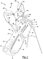
- a golf bag 10 is provided and includes a first support member 12, a second support member 14, and a substantially tubular body 16.
- the golf bag 10 may define a length extending between the first support member 12 and the second support member 14 and may further include a front 20, a rear 22, and opposite sides 24 extending between the front 20 and the rear 22 to define corresponding panels of the golf bag 10 that extend through the length of the golf bag 10.
- the lip may be formed from an abrasion-resistant material to prevent damaging the head portions of the golf clubs in contact therewith.
- the first support member 12 may define one or more dividers (none shown) extending across the club opening 28 to define at least two compartments to suitably arrange and organize the golf clubs received within the interior void 18.
- the second support member 14 is disposed on an opposite end of the golf bag 10 than the first support member 12 and may include an inner surface and a ground-engaging surface disposed on an opposite side of the second support member 14.
- the inner surface may support handles (e.g., grips) of each golf club received by the interior void 18 through the club opening 28 defined by the first support member 12.
- the second support member 14 may be generally oriented to contact a ground surface when the golf bag 10 is not being carried and, therefore, may provide abrasion-resistance and frictional engagement with the ground surface 2.
- the second support member 14 may be formed from one or more materials that impart durability and wear-resistance, as well as enhance grip with the ground surface 2. For example, rubber may form at least a portion of the second support member 14.
- the golf bag 10 may include one or more shoulder straps 100, 200 attached to one or more anchor points 36 disposed on the body 16 via one or more fastening straps 38.
- the fastening straps 38 may provide the shoulder straps 100, 200 with a degree of movement relative to the body 16 to help facilitate placement of the shoulder straps 100, 200 over the shoulders of a golfer.
- the lengths of the fastening straps 38 may be selectively increased or decreased to adjust an amount of separation between the shoulder straps 100, 200 and the body 16 of the golf bag 10.
- the golf bag 10 may also include a back pad 42 that attaches to at least one of the shoulder straps 100, 200 to enhance comfort for the golfer when transporting the golf bag 10. Further, the back pad 42 transmits loads from the second ends 112, 212 of the respective straps 100, 200 to the anchor points 36 via the straps 38.
- the main bodies 102, 202 of the shoulder straps 100, 200 may include a substantially straight configuration between each first end 110, 210 and each second end 112, 212.
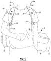
- FIG. 3 shows each of the tension elements 120, 220 in their tightened state.
- the tension element 120 applies a force on the first end 110 and on the second end 112 of the first strap 100 and the tension element 220 applies a force on the first end 210 and on the second end 220 of the second strap 200.
- the applied forces change the relative position of the first ends 110, 210 and the second ends 112, 212 and, as a result, change the position of the main bodies 102, 202 from the straight configuration ( FIG. 2 ) to a curved configuration ( FIG. 3 ). That is, the shape of the main body 102 changes as the tension element 120 of the first shoulder strap 100 changes the relative position of the first end 110 and the second end 112.
- the shape of the main body 202 changes as the tension element 220 of the second shoulder strap 200 changes the relative position of the first end 210 and the second end 212.
- the shape of the main body 202 of the second shoulder strap 200 changes from the straight configuration to a curved configuration when the tension element 220 is in the tightened state.
- the tension elements 210, 220 place the corresponding shoulder straps 100, 200 under tension while being supported by the shoulders of the golfer and the golf bag 10 is being transported.
- the curved configurations allow the shoulder straps 100, 200 to tighten and grip around the shoulders of the golfer to thereby place the golf bag 10 under tension so that movement of the golf bag 10 relative to the body of the golfer is restricted while the golf bag 10 is being transported.
- the curved configurations of the main bodies 102, 202 may include an S-shaped configuration, a C-shaped configuration, or other curved configurations having a desirable shape that suitably places the shoulder straps 100, 200 under tension for transporting the golf bag 10.
- such shapes may increase the comfort of the golfer when carrying the bag, as the golfer has the ability to independently adjust a shape of each strap 100, 200 such that a shape of each strap 100, 200 can be tailored to the specific shape of the golfer's body.
- the first strap 100 may be adjusted to a partially curved configuration between the straight configuration shown in FIG. 2 and the fully curved configuration shown in FIG. 3 while the second strap 200 may be adjusted to the fully curved configuration shown in FIG. 3 . Any adjustment between the straight configuration of FIG. 2 and the fully curved configuration of FIG. 3 is possible depending on the tension of the tension elements 210, 220.
- An actuation mechanism 130 may be associated with each strap 100, 200 to adjust a tension in each tension element 210, 220 and, thus, a shape of each strap 100, 200.
- the actuation mechanism 130 is supported by the main body 102 of the first shoulder strap 100 and provides a locking mechanism 144 ( FIG. 12 ) that maintains the tension element 120 in the tightened state in a first mode of operation and maintains the tension element 120 in the relaxed state in a second mode of operation.
- the second shoulder strap 200 may also include an actuation mechanism 230 and locking mechanism 144 supported by its main body 202 that maintains the tension element 220 in the tightened state in a first mode of operation and maintains the tension element 220 in the relaxed state in a second mode of operation.
- the actuation mechanisms 130, 230 are independently adjustable to allow a user to adjust a configuration of each strap 100, 200 independently from one another.
- the main body 102 defines a length extending between the first end 110 and the second end 112 and includes an inner edge 104 and an outer edge 106 extending between the first end 110 and the second end 112 to define a perimeter of the main body 102.
- the inner edge 104 may be disposed closer to the center of the golfer's body than the outer edge 106 when the shoulder strap 100 is placed on the shoulder (e.g., right shoulder) of the golfer.
- the actuation mechanism 130 is disposed at a midpoint along the length of the main body 102, as shown in FIGS. 4 and 5 .
- the main body 102 may define an upper portion 2 disposed between the second end 112 and the actuation mechanism 130 and a lower portion 4 disposed between the first end 110 and the actuation mechanisms 130.
- the tension element 120 may include a first portion 121 associated with the lower portion 4 of the main body 102 and a second portion 122 associated with the upper portion 2 of the main body 102.
- the first portion 121 corresponds to a first tensioning cable and the second portion 122 corresponds to a second tensioning cable separate from the first cable 121.
- the upper portion 2 may include an upper flexion region 420 and the lower portion 2 may include a lower flexion region 440.
- the upper flexion region 420 and the lower flexion region 440 may cooperate to enhance the ability of the main body 102 to flex, bend, or otherwise change its shape, when the tension element 120 is in the tightened state.
- FIG. 5 shows the upper flexion region 420 allowing the inner edge 104 at the upper portion 2 to flex away from the center of the main body 102 as the second end 112 is pulled by the second portion 122 of the tension element 120 toward the actuation mechanism 130.
- the lower flexion region 440 allows the inner edge 104 at the lower portion 4 to flex toward the center of the main body 102 as the first end 110 is pulled by the first portion 121 of the tension element 120 toward the actuation mechanism 130.
- the first portion 121 and the second portion 122 are configured to pull their associated ends 110, 112 toward the actuation mechanism 130 when the tension element 120 is in the tightened state such that the first end 110 and the second end 112 converge toward one another.
- the main body 102 may be defined by a core 602 extending along the length of the main body 102 and having a front surface and a shoulder-engaging surface disposed on an opposite side of the core 602 than the front surface.
- a core cover 603 is disposed on the front surface of the core 602 and includes substantially the same shape as the core 602.
- the core 602 may be formed from one or more polymer foam materials or other materials suitable to provide a degree of cushioning for the shoulder while transporting the golf bag 10. As described in greater detail below and with reference to FIGS. 6-11 , the core 602 may include a series of gaps 1010, 1020 disposed along the length of the main body 102.
- the fastening straps 38 associated with the first attachment location 160 ( FIGS. 1-3 ) and the second attachment location 162 ( FIGS. 1-3 ) may be secured to the main body 102 via stitching 6 at locations proximate to the ends 110, 112 of the main body 102.
- the fastening straps 38 may be secured to either or both of the core 602 and the cover 402.
- the stitching 6 may be additionally or alternatively used to secure at least a portion of the tension element 120 to the core 602 and/or the cover 402, as will be described below.
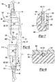
- FIGS. 6 and 9 provide a front view of the first shoulder strap 100 having the cover 402 removed from the main body 102 to expose the core 602, the core cover 603, and the tension element 120.
- FIG. 6 shows the first shoulder strap 100 having the straight configuration when the tension element 120 is in the relaxed state
- FIG. 9 shows the first shoulder strap 100 having the curved or S-shaped configuration when the tension element 120 is in the tightened state.
- the core cover 603 includes substantially the same shape as the core 602 and extends along the length of the main body 102 between the first end 110 and the second end 112.
- the views of FIGS. 6 and 9 show a portion of the core cover 603 removed to expose features that are disposed between the core 602 and the cover layer 603.
- changing the relative position of the first end 110 and the second end 112 likewise changes the shape of the main body 102 (i.e., between the straight configuration and the curved or S-shaped configuration). While the gaps 1010, 1020 are described and shown as being disposed on opposite sides of the core 602, the gaps 1010, 1020 could alternatively be disposed on the same side of the core 602.
- the recesses 625 and the retaining balls 825 may facilitate attachment of the proximal ends 123, 124 of the respective portions 121, 122 to the core 602, thereby fixing the ends 123, 124 for movement with the core 602. Fixing the ends 123, 124 for movement with the core 602 causes the ends 110, 112 to be pulled toward the actuation mechanism 130 when a force F ( FIG. 9 ) is applied on each end 110, 112 of the main body 102 by the actuation mechanism 130.
- the core 602 is shown as including a channel 620 disposed along the length of the core 602 that receives the length of the first guide member 127 and the first portion 121 of the tension element 120. While not shown in the view of FIG. 7 , the channel 620 also receives the length of the second guide member 128 and the second portion 122 of the tension element 120 in an identical fashion.
- the channel 620 may correspond to a groove formed into the front surface of the core 602 that includes a depth occupied by at least a portion of the thicknesses of the portions 121, 122 of the tension element 120 as well as the thicknesses of the guide members 127, 128 enclosing the portions 121, 122.
- FIG. 8 provides a cross-sectional view taken along line 8-8 of FIG. 6 showing the channel 620 formed in the core 602 and receiving the first guide member 127 enclosing the first portion 121 of the tension element 120 in a substantially coaxial relationship.
- the guide members 127, 128 are lined or coated with a low-friction material, such as a lubricous polymer, that facilitates movement of the portions 121, 122 of the tension element 120 relative to and within the guide members 127, 128.
- FIGS. 6 and 9 show the actuation mechanism 130 as being supported by the main body 102 between the first end 110 and the second end 112.
- the actuation mechanism 130 selectively applies the first force F 1 and the second force F 2 on the first end 110 and the second end 112, respectively, to move the tension element 120 between the relaxed state ( FIG. 6 ) and the tightened state ( FIG. 9 ).
- the portions 121, 122 of the tension element 120 apply a force on the respective ends 110, 112 of the main body 102 to move the ends 110, 112 toward the actuation mechanism 130. Movement of the ends 110, 112 toward the actuation mechanism 130 causes the core 602 and, thus, the main body 102 to take the S-shaped configuration.
- the actuation mechanism 130 may allow the portions 121, 122 to be tightened in increments, thereby resulting in the ends 110, 112 of the main body 102 to be increasingly pulled toward the actuation mechanism 130.
- the actuation mechanism 130 may include a control mechanism such as a knob 134 that can be manipulated (e.g., rotated in the clockwise direction 132) to simultaneously retract the portions 121, 122 of the tension element 120 into the actuation member 130.
- retracting the first portion 121 and the second portion 122 decreases the effective length of each portion 121, 122 and, as a result, applies a force F 1 , F 2 on each end 110, 112 of the main body 102, thereby drawings to ends 110, 112 toward one another.
- the applied forces F 1 , F 2 pull each end 110, 112 of the main body 102 toward the actuation mechanism 130 and, as a result, causes the main body 102 to move from the straight configuration ( FIG.
- the ends 110, 112 of the main body 102 converge toward one another when the actuation mechanism 130 applies the forces F 1 , F 2 via the portions 121, 122 of the tension member 120.
- the gaps 1010, 1020 enhance the ability of the main body 102 to flex, bend, or otherwise change its shape at the flexion regions 440, 420, as the first end 110 and the second end 112 of the main body 102 are pulled in the foregoing manner.
- the first series of gaps 1010 includes a first portion 1011 associated with gaps extending from the inner edge 104 of the core 602 toward the center of the core 602.
- the channel 620 may traverse the first portion 1011 of the first series of gaps 1010 to allow the first portion 121 of the tension element 120, when received by the channel 620, to be placed in a position that traverses the first portion 1011 of the first series of gaps 1010.
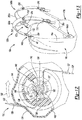
- FIG. 10 shows each gap of the first portion 1011 having a respective width W 11 that separates segments of the core 602 located between adjacent gaps 1010.
- the second series of gaps 1020 associated with the upper portion 2 may include a first portion 1021 associated with gaps extending from the outer edge 106 of the core 602 toward the center of the core 602.
- the channel 620 may traverse the first portion 1021 of the second series of gaps 1020 to allow the second portion 122 of the tension element 120, when received by the channel 620, to be placed in a position that traverses the first portion 1021 of the second series of gaps 1020.
- FIG. 10 shows each gap of the first portion 1021 having a respective width W 21 that separates segments of the core 602 located between adjacent gaps 1020.
- the gaps 1020 of the first portion 1021 may facilitate bending and flexing of the outer edge 106 in the opposite direction toward the center of the core 602 when the foregoing second force F 2 ( FIG. 9 ) is applied on the second end 112 of the core 602.
- FIG. 11 shows the width W 21 of the gaps of the first portion 1021 reducing and closing as the outer edge 104 flexes and bends toward the center of the core 602 to attain the curve at the upper portion 2 that contributes to the curved or S-shaped configuration.
- the distal ends 125, 126 of the portions 121, 122 may be attached to a spool 137 or reel having a common axis of rotation with the shaft 138.
- ends of the corresponding guide members 127, 128 may be attached to the housing 135 and/or may be secured to at least one of the core 602 and the core cover 603.
- the spool 137 or reel may wind the portions 121, 122 of the tension element 120 when the knob 134 is rotated in the clockwise direction 132 relative to the view shown in FIG. 9 to retract the portions 121, 122 and reduce slack in the tension element 120.
- the spool 137 includes a single-groove spool.
- the actuation mechanism 130 may also include a ratchet mechanism 140 having a common axis of rotation with the shaft 138.
- the ratchet mechanism 140 may include a plurality of sloped teeth 142 positioned circumferentially around the axis of the ratchet mechanism 140 that mate with a locking mechanism 144 to retain a predetermined length of the portions 121, 122, of the tension element 120 as the knob 134 is rotated relative to the core 602.
- the locking mechanism 144 may be disposed within an aperture of the housing 136 and a biasing member 146 may bias the locking mechanism 144 into locked engagement with the sloped teeth 142 of the ratchet mechanism 140.
- the locking mechanism 144 inhibits counterclockwise rotation of the knob 134 and loosening of the first and second portions 121, 122, respectively, of the tension element 120.
- the sloped teeth 142 do not inhibit rotation of the knob 134 in the clockwise direction 132 because the locking mechanism 144 is allowed to slide over the teeth 142.
- the locking mechanism 144 automatically engages the teeth 142 to allow the user to incrementally adjust the amount of the portions 121, 122 that are drawn into the actuation mechanism 130.
- the second shoulder strap 200a may include a main body 202a having a first end 210 attached to a third attachment location 170a of the carry bag 10a and a second end 212 attached to a fourth attachment location 172a of the carry bag 10a.
- FIGS. 14 and 16 provide a front view of the first shoulder strap 100a (e.g., right shoulder strap) of FIG. 13 illustrating the straight configuration ( FIG. 14 ) when the tension element 120 is in the relaxed state and having the curved or S-shaped configuration ( FIG. 16 ) when the tension element 120 is in the tightened state.
- the straps 100a, 200a are mirror images of one another but are otherwise identical. Accordingly, a detailed description of the second shoulder strap 200a and associated actuation mechanism 230 is foregone.
- the main body 102a defines a length extending between the ends 110, 112 and includes the inner edge 104 and the outer edge 106 extending between ends 110, 112 to define the perimeter of the main body 102a.
- the main body 102a may include a core 602a extending along the length of the main body to provide a degree of cushioning for the corresponding shoulder under the load applied by the carry bag 10a.
- the main body 102a of the strap 100a associated with the carry bag 10a may change its shape when the tension element 120 moves between the relaxed state and the tightened state. For instance, FIG.
- FIG. 16 shows the main body 102a changing its shape from the straight configuration to the curved or S-shaped configuration when the first portion 121 of the tension element 120 pulls the first end 110 of the main body 102a toward the actuation mechanism 130 and when the second portion 122 of the tension element 120 simultaneously pulls the second end 112 of the main body 102a toward the actuation mechanism 130.
- the main body 102a may also include a cover 402a that covers and is secured to the front surface of the core 602a.
- the cover 402a includes a flexible portion 406a disposed within each of the flexion regions 420, 440 and a durable/rigid portion 404 disposed adjacent to each of the ends 110, 112 of the main body 102a and also between the flexion regions 420a, 440 proximate to the actuation mechanism 130.
- the shoulder strap 100 for the golf bag 10 of FIGS. 1-11 provides the channel 620 disposed along the length of its main body 102 to facilitate slidability of the portions 121, 122 and to prevent the portions 121, 122 from laterally moving out of position relative to the core 602a
- the shoulder strap 100a of the carry bag 10a instead provides at least one series of holes 1402, 1404 formed through the flexible portion 406a of the cover 402 and disposed along a portion of the length of the main body 102a.
- the at least one series of holes 1402, 1404 may include eyelets and/or other engagement features such as fabric or mesh loops that receive corresponding ones of the portions 121, 122 of the tension element 120, thereby preventing the portions 121, 122 from laterally moving out of position.
- a lower series of holes 1404 associated with the lower portion 4 of the main body 102a may retain the first portion 121 of the tension element in a position that traverses the first series of gaps 1010 that extend along the inner edge 104 and an upper series of holes 1402 associated with the upper portion 2 of the main body 102a may retain the second portion 122 of the tension element 120 in a position that traverses the second series of gaps 1020 that extend along the outer edge 106.
- the upper series of holes 1402 may be formed through the flexible portions 406a of cover 402a at the upper flexion region 420 while the lower series of holes 1404 may be formed through the flexible portion 406a at the lower flexion region 440.
- the lower series of holes 1402 may extend along the inner edge 104 while the upper series of holes 1402 may extend along the outer edge 106.
- the holes 1402, 1404 allow the tension element 120 to be threaded through the cover 402 to maintain a relative position of the first portion 121 of the tension element 120 and the inner edge 104 and a relative position of the second portion 122 of the tension element 120 and the outer edge 106. Threading the tension element 120 through the cover 402 results in a portion of the tension element 120 being exposed at an outer surface of the cover 402 and a portion of the tension element 120 being disposed between the cover 402 and the core 602a, as shown in FIG. 15 .
- FIG. 15 provides a cross-sectional view taken along line 15-15 of FIG. 14 showing the series of holes 1402 formed through the flexible portion 406a of the cover 402a and receiving the first portion 121 of the tension element 120.
- the first portion 121 of the tension element 120 may weave through the series of holes 1404 so that the tension element 120 includes segments extending along its length that alternate between extending outside of the cover 402a and extending between the cover 402a and the core 602a.
- the first portion 121 may maintain its position relative to and traversing the first series of gaps 1010.
- the second portion 122 of the tension element 120 may similarly weave through the upper series of holes 1402 formed through the flexible portion 406a of the cover 402a at the upper flexion region 420. Additionally, the cover 402a and the portions 121, 122 of the tension element 120 may be secured to the core 602a via stitching 6 at the segments of the core 602a between adjacent gaps of the first series of gaps 1010 and the second series of gaps 1020.
- the holes of at least one of the series of holes 1402, 1404 are lined or coated with a low-friction material, such as a lubricous polymer, that facilitates movement of the portions 121, 122 of the tension element 120 relative to each hole 1402, 1404.
- the holes 1402, 1404 may include a suitable substantially rigid material that is coated with a lubricous coating to further facilitate movement of the portions 121, 122 relative to the holes 1402, 1404, as the tension element 120 is moved relative to the core 602a by the actuation mechanism 130.
- the substantially rigid material may impart rigidity to the holes 1402, 1404 to prevent bending and kinking of the holes 1402, 1404 and/or the portions 121, 122 of the tension element 120 extending therethrough when the portions 121, 122 are tightened by the actuation mechanism 130.
- straps 100, 200 are described and shown in conjunction with a golf bag 10 and the straps 100a, 200a are described and shown in conjunction with a carry bag 10a, the straps 100, 200 could be used in conjunction with the carry bag 10a and the straps 100a, 200a could be used in conjunction with the golf bag 10a.
- Changing the relative position between said first end and said second may include changing a shape of said main body.
- Said actuation mechanism may be rotatably supported by said main body and may include a locking mechanism operable to maintain said tension element in said tightened state in a first mode of operation and may be operable to maintain said tension element in said relaxed state in a second mode of operation.
- Said main body may include a series of gaps disposed along a length of said main body, said gaps permitting said main body to flex when said tension element is moved from said relaxed state to said tightened state.
- Said gaps may include a decreasing width in a direction extending from an edge of said main body toward a center of said main body.
- Said gaps may be reduced when said tension element is moved from said relaxed state to said tightened state.
- the strap may further comprise an actuation mechanism supported by said main body and operable to move said tension element between said tightened state and said relaxed state.
- Said main body may include a first series of gaps and a second series of gaps disposed along a length of said main body, said first series of gaps and said second series of gaps permitting said main body to flex when said tension element is moved from said relaxed state to said tightened state.
- Said tension element may traverse said first series of gaps and said second series of gaps between said first end and said second end.
- Said first series of gaps and said second series of gaps may be reduced when said tension element is moved from said relaxed state to said tightened state.
Landscapes
- Health & Medical Sciences (AREA)
- General Health & Medical Sciences (AREA)
- Physical Education & Sports Medicine (AREA)
- Purses, Travelling Bags, Baskets, Or Suitcases (AREA)
Applications Claiming Priority (3)
| Application Number | Priority Date | Filing Date | Title |
|---|---|---|---|
| US14/805,964 US9901163B2 (en) | 2015-07-22 | 2015-07-22 | Cable-tensioning system strap |
| EP16745357.0A EP3325111B1 (de) | 2015-07-22 | 2016-07-21 | Kabelspannsystemband |
| PCT/US2016/043327 WO2017015453A1 (en) | 2015-07-22 | 2016-07-21 | Cable-tensioning system strap |
Related Parent Applications (1)
| Application Number | Title | Priority Date | Filing Date |
|---|---|---|---|
| EP16745357.0A Division EP3325111B1 (de) | 2015-07-22 | 2016-07-21 | Kabelspannsystemband |
Publications (2)
| Publication Number | Publication Date |
|---|---|
| EP3763423A1 true EP3763423A1 (de) | 2021-01-13 |
| EP3763423B1 EP3763423B1 (de) | 2024-01-24 |
Family
ID=56555843
Family Applications (2)
| Application Number | Title | Priority Date | Filing Date |
|---|---|---|---|
| EP20194024.4A Active EP3763423B1 (de) | 2015-07-22 | 2016-07-21 | Kabelspannsystemband |
| EP16745357.0A Not-in-force EP3325111B1 (de) | 2015-07-22 | 2016-07-21 | Kabelspannsystemband |
Family Applications After (1)
| Application Number | Title | Priority Date | Filing Date |
|---|---|---|---|
| EP16745357.0A Not-in-force EP3325111B1 (de) | 2015-07-22 | 2016-07-21 | Kabelspannsystemband |
Country Status (4)
| Country | Link |
|---|---|
| US (3) | US9901163B2 (de) |
| EP (2) | EP3763423B1 (de) |
| CN (2) | CN111109827B (de) |
| WO (1) | WO2017015453A1 (de) |
Families Citing this family (10)
| Publication number | Priority date | Publication date | Assignee | Title |
|---|---|---|---|---|
| US20160058127A1 (en) * | 2014-08-28 | 2016-03-03 | Boa Technology Inc. | Devices and methods for enhancing the fit of boots and other footwear |
| US10954055B2 (en) | 2017-03-08 | 2021-03-23 | Yeti Coolers, Llc | Container with magnetic closure |
| CA3054439A1 (en) | 2017-03-08 | 2018-09-13 | Yeti Coolers, Llc | Container with magnetic closure |
| CO2018004107A1 (es) * | 2018-04-17 | 2019-10-21 | The Frenchie Group S A S | Mecanismo trasero de protección antirrobo con apertura magnética y sistema de tirantes autoajustables para objetos destinados a guardar elementos como por ejemplo maletines, mochilas o maletas. |
| US10772410B2 (en) * | 2019-01-04 | 2020-09-15 | The North Face Apparel Corp. | Cinch pack |
| USD889842S1 (en) * | 2019-06-05 | 2020-07-14 | Callaway Golf Company | Pair of bag straps |
| US11950685B2 (en) * | 2020-10-05 | 2024-04-09 | Stumpworx Llc | Pressure-relieving flexural load bearing strap and method for manufacturing same |
| US12440356B2 (en) * | 2020-10-05 | 2025-10-14 | Stumpworx Llc | Pressure-relieving flexural load-bearing strap and related systems and methods |
| US11992104B2 (en) * | 2022-02-16 | 2024-05-28 | Yeti Coolers, Llc | Container with resealable closure |
| CN118161109B (zh) * | 2024-05-13 | 2024-07-19 | 湖南省华芯医疗器械有限公司 | 一种牵引机构和内窥镜 |
Citations (10)
| Publication number | Priority date | Publication date | Assignee | Title |
|---|---|---|---|---|
| US5143266A (en) * | 1986-01-10 | 1992-09-01 | Butler Creek Corporation | Harness |
| GB2378936A (en) * | 2001-08-21 | 2003-02-26 | Styles Alan | Adjustable strap |
| EP1380227A2 (de) * | 2002-07-12 | 2004-01-14 | K-2 Corporation | Rucksack mit einer am Schulterriemen befestigten Hebeschnalle |
| US20090014485A1 (en) * | 2007-07-09 | 2009-01-15 | Tony Yeung | Carrier device having adjustable strap and the usage thereof |
| US7600660B2 (en) * | 2004-03-11 | 2009-10-13 | Raymond Nevin Kasper | Harness tightening system |
| US20100072091A1 (en) * | 2008-09-22 | 2010-03-25 | Quartarone Frank A | Shoulder Strap With Reinforcing Strip |
| US20110284608A1 (en) * | 2010-05-21 | 2011-11-24 | Iris Staudecker | Rucksack with rear ventilation zone |
| US20120012628A1 (en) * | 2010-03-30 | 2012-01-19 | Adidas Ag | Insert For A Carrying Strap |
| US20120037674A1 (en) * | 2009-02-26 | 2012-02-16 | Daymen Canada Acquisition Ulc | Self adjusting contoured strap device and method |
| US20120241341A1 (en) * | 2011-03-23 | 2012-09-27 | Sri Sports Limited | Shock-absorbing golf bag and strap system |
Family Cites Families (9)
| Publication number | Priority date | Publication date | Assignee | Title |
|---|---|---|---|---|
| US6640344B2 (en) * | 2001-09-07 | 2003-11-04 | J. D'addario & Co., Inc. | Shoulder pad |
| CN1262221C (zh) * | 2002-04-17 | 2006-07-05 | 伊利诺斯器械工程公司 | 有弹性的侧面解扣 |
| US7367522B2 (en) * | 2005-10-14 | 2008-05-06 | Chin Chu Chen | String fastening device |
| US7992749B2 (en) * | 2006-03-30 | 2011-08-09 | Nike, Inc. | Support element for a carry strap |
| CN200938919Y (zh) * | 2006-08-17 | 2007-08-29 | 橡果国际电子科技(上海)有限公司 | 一种背包 |
| US8936962B2 (en) * | 2009-03-13 | 2015-01-20 | Nec Corporation | Optical modulator and method for manufacturing same |
| US8673783B2 (en) * | 2010-07-02 | 2014-03-18 | Taiwan Semiconductor Manufacturing Company, Ltd. | Metal conductor chemical mechanical polish |
| US9736606B2 (en) * | 2014-08-01 | 2017-08-15 | Qualcomm Incorporated | Editing of higher-order ambisonic audio data |
| US9730507B2 (en) * | 2015-06-08 | 2017-08-15 | Eric Wendler | Retractable shoulder strap for portable objects |
-
2015
- 2015-07-22 US US14/805,964 patent/US9901163B2/en not_active Expired - Fee Related
-
2016
- 2016-07-21 CN CN201911317289.9A patent/CN111109827B/zh active Active
- 2016-07-21 EP EP20194024.4A patent/EP3763423B1/de active Active
- 2016-07-21 CN CN201680052192.8A patent/CN108348808B/zh active Active
- 2016-07-21 WO PCT/US2016/043327 patent/WO2017015453A1/en not_active Ceased
- 2016-07-21 EP EP16745357.0A patent/EP3325111B1/de not_active Not-in-force
-
2018
- 2018-01-23 US US15/877,905 patent/US10349727B2/en active Active
-
2019
- 2019-06-04 US US16/431,138 patent/US11006735B2/en active Active
Patent Citations (10)
| Publication number | Priority date | Publication date | Assignee | Title |
|---|---|---|---|---|
| US5143266A (en) * | 1986-01-10 | 1992-09-01 | Butler Creek Corporation | Harness |
| GB2378936A (en) * | 2001-08-21 | 2003-02-26 | Styles Alan | Adjustable strap |
| EP1380227A2 (de) * | 2002-07-12 | 2004-01-14 | K-2 Corporation | Rucksack mit einer am Schulterriemen befestigten Hebeschnalle |
| US7600660B2 (en) * | 2004-03-11 | 2009-10-13 | Raymond Nevin Kasper | Harness tightening system |
| US20090014485A1 (en) * | 2007-07-09 | 2009-01-15 | Tony Yeung | Carrier device having adjustable strap and the usage thereof |
| US20100072091A1 (en) * | 2008-09-22 | 2010-03-25 | Quartarone Frank A | Shoulder Strap With Reinforcing Strip |
| US20120037674A1 (en) * | 2009-02-26 | 2012-02-16 | Daymen Canada Acquisition Ulc | Self adjusting contoured strap device and method |
| US20120012628A1 (en) * | 2010-03-30 | 2012-01-19 | Adidas Ag | Insert For A Carrying Strap |
| US20110284608A1 (en) * | 2010-05-21 | 2011-11-24 | Iris Staudecker | Rucksack with rear ventilation zone |
| US20120241341A1 (en) * | 2011-03-23 | 2012-09-27 | Sri Sports Limited | Shock-absorbing golf bag and strap system |
Also Published As
| Publication number | Publication date |
|---|---|
| US9901163B2 (en) | 2018-02-27 |
| US10349727B2 (en) | 2019-07-16 |
| CN111109827A (zh) | 2020-05-08 |
| EP3325111B1 (de) | 2020-09-09 |
| EP3763423B1 (de) | 2024-01-24 |
| CN108348808B (zh) | 2020-01-21 |
| CN108348808A (zh) | 2018-07-31 |
| US20190281958A1 (en) | 2019-09-19 |
| US20180146768A1 (en) | 2018-05-31 |
| US11006735B2 (en) | 2021-05-18 |
| US20170020270A1 (en) | 2017-01-26 |
| WO2017015453A1 (en) | 2017-01-26 |
| EP3325111A1 (de) | 2018-05-30 |
| CN111109827B (zh) | 2022-02-18 |
Similar Documents
| Publication | Publication Date | Title |
|---|---|---|
| US11006735B2 (en) | Cable-tensioning system strap | |
| EP2371232B1 (de) | Einsatz für einen Tragegurt | |
| US10058163B2 (en) | Adjustable backpack | |
| US5615811A (en) | Retractable carrying device | |
| CN113226105B (zh) | 分区动态系带系统 | |
| JP6275168B2 (ja) | バックパック | |
| EP2672937B1 (de) | Spannsystem für einen orthopädischen artikel | |
| WO2010117749A2 (en) | Wrist brace | |
| WO2012154978A1 (en) | Articulating multi-adjustable divider system | |
| US20130254987A1 (en) | Waist transfer belt | |
| US20090014485A1 (en) | Carrier device having adjustable strap and the usage thereof | |
| US12138497B2 (en) | Belt having a retracting lanyard | |
| WO2022256523A1 (en) | Pedal with adjustment dial system | |
| WO2013104709A1 (en) | A hand strap for a skiing pole or similar | |
| WO2014145379A1 (en) | Adjustable strap for bags or instruments | |
| DK201870045A1 (en) | A shoulder strap | |
| CA2733818A1 (en) | Hockey training apparatus |
Legal Events
| Date | Code | Title | Description |
|---|---|---|---|
| PUAI | Public reference made under article 153(3) epc to a published international application that has entered the european phase |
Free format text: ORIGINAL CODE: 0009012 |
|
| STAA | Information on the status of an ep patent application or granted ep patent |
Free format text: STATUS: THE APPLICATION HAS BEEN PUBLISHED |
|
| AC | Divisional application: reference to earlier application |
Ref document number: 3325111 Country of ref document: EP Kind code of ref document: P |
|
| AK | Designated contracting states |
Kind code of ref document: A1 Designated state(s): AL AT BE BG CH CY CZ DE DK EE ES FI FR GB GR HR HU IE IS IT LI LT LU LV MC MK MT NL NO PL PT RO RS SE SI SK SM TR |
|
| STAA | Information on the status of an ep patent application or granted ep patent |
Free format text: STATUS: REQUEST FOR EXAMINATION WAS MADE |
|
| 17P | Request for examination filed |
Effective date: 20210713 |
|
| RBV | Designated contracting states (corrected) |
Designated state(s): AL AT BE BG CH CY CZ DE DK EE ES FI FR GB GR HR HU IE IS IT LI LT LU LV MC MK MT NL NO PL PT RO RS SE SI SK SM TR |
|
| STAA | Information on the status of an ep patent application or granted ep patent |
Free format text: STATUS: EXAMINATION IS IN PROGRESS |
|
| 17Q | First examination report despatched |
Effective date: 20211221 |
|
| P01 | Opt-out of the competence of the unified patent court (upc) registered |
Effective date: 20230515 |
|
| GRAP | Despatch of communication of intention to grant a patent |
Free format text: ORIGINAL CODE: EPIDOSNIGR1 |
|
| STAA | Information on the status of an ep patent application or granted ep patent |
Free format text: STATUS: GRANT OF PATENT IS INTENDED |
|
| RIC1 | Information provided on ipc code assigned before grant |
Ipc: A45F 3/14 20060101ALN20230830BHEP Ipc: A45F 3/04 20060101ALI20230830BHEP Ipc: A63B 55/00 20150101AFI20230830BHEP |
|
| RIC1 | Information provided on ipc code assigned before grant |
Ipc: A45F 3/14 20060101ALN20230906BHEP Ipc: A45F 3/04 20060101ALI20230906BHEP Ipc: A63B 55/00 20150101AFI20230906BHEP |
|
| INTG | Intention to grant announced |
Effective date: 20230922 |
|
| RIC1 | Information provided on ipc code assigned before grant |
Ipc: A45F 3/14 20060101ALN20230914BHEP Ipc: A45F 3/04 20060101ALI20230914BHEP Ipc: A63B 55/00 20150101AFI20230914BHEP |
|
| GRAS | Grant fee paid |
Free format text: ORIGINAL CODE: EPIDOSNIGR3 |
|
| GRAA | (expected) grant |
Free format text: ORIGINAL CODE: 0009210 |
|
| STAA | Information on the status of an ep patent application or granted ep patent |
Free format text: STATUS: THE PATENT HAS BEEN GRANTED |
|
| AC | Divisional application: reference to earlier application |
Ref document number: 3325111 Country of ref document: EP Kind code of ref document: P |
|
| AK | Designated contracting states |
Kind code of ref document: B1 Designated state(s): AL AT BE BG CH CY CZ DE DK EE ES FI FR GB GR HR HU IE IS IT LI LT LU LV MC MK MT NL NO PL PT RO RS SE SI SK SM TR |
|
| REG | Reference to a national code |
Ref country code: GB Ref legal event code: FG4D |
|
| REG | Reference to a national code |
Ref country code: CH Ref legal event code: EP |
|
| REG | Reference to a national code |
Ref country code: DE Ref legal event code: R096 Ref document number: 602016085554 Country of ref document: DE |
|
| REG | Reference to a national code |
Ref country code: IE Ref legal event code: FG4D |
|
| REG | Reference to a national code |
Ref country code: LT Ref legal event code: MG9D |
|
| REG | Reference to a national code |
Ref country code: NL Ref legal event code: MP Effective date: 20240124 |
|
| PG25 | Lapsed in a contracting state [announced via postgrant information from national office to epo] |
Ref country code: NL Free format text: LAPSE BECAUSE OF FAILURE TO SUBMIT A TRANSLATION OF THE DESCRIPTION OR TO PAY THE FEE WITHIN THE PRESCRIBED TIME-LIMIT Effective date: 20240124 |
|
| PG25 | Lapsed in a contracting state [announced via postgrant information from national office to epo] |
Ref country code: NL Free format text: LAPSE BECAUSE OF FAILURE TO SUBMIT A TRANSLATION OF THE DESCRIPTION OR TO PAY THE FEE WITHIN THE PRESCRIBED TIME-LIMIT Effective date: 20240124 |
|
| PG25 | Lapsed in a contracting state [announced via postgrant information from national office to epo] |
Ref country code: IS Free format text: LAPSE BECAUSE OF FAILURE TO SUBMIT A TRANSLATION OF THE DESCRIPTION OR TO PAY THE FEE WITHIN THE PRESCRIBED TIME-LIMIT Effective date: 20240524 |
|
| PGFP | Annual fee paid to national office [announced via postgrant information from national office to epo] |
Ref country code: GB Payment date: 20240530 Year of fee payment: 9 |
|
| PG25 | Lapsed in a contracting state [announced via postgrant information from national office to epo] |
Ref country code: LT Free format text: LAPSE BECAUSE OF FAILURE TO SUBMIT A TRANSLATION OF THE DESCRIPTION OR TO PAY THE FEE WITHIN THE PRESCRIBED TIME-LIMIT Effective date: 20240124 |
|
| PG25 | Lapsed in a contracting state [announced via postgrant information from national office to epo] |
Ref country code: GR Free format text: LAPSE BECAUSE OF FAILURE TO SUBMIT A TRANSLATION OF THE DESCRIPTION OR TO PAY THE FEE WITHIN THE PRESCRIBED TIME-LIMIT Effective date: 20240425 |
|
| REG | Reference to a national code |
Ref country code: AT Ref legal event code: MK05 Ref document number: 1651727 Country of ref document: AT Kind code of ref document: T Effective date: 20240124 |
|
| PG25 | Lapsed in a contracting state [announced via postgrant information from national office to epo] |
Ref country code: RS Free format text: LAPSE BECAUSE OF FAILURE TO SUBMIT A TRANSLATION OF THE DESCRIPTION OR TO PAY THE FEE WITHIN THE PRESCRIBED TIME-LIMIT Effective date: 20240424 Ref country code: HR Free format text: LAPSE BECAUSE OF FAILURE TO SUBMIT A TRANSLATION OF THE DESCRIPTION OR TO PAY THE FEE WITHIN THE PRESCRIBED TIME-LIMIT Effective date: 20240124 |
|
| PG25 | Lapsed in a contracting state [announced via postgrant information from national office to epo] |
Ref country code: ES Free format text: LAPSE BECAUSE OF FAILURE TO SUBMIT A TRANSLATION OF THE DESCRIPTION OR TO PAY THE FEE WITHIN THE PRESCRIBED TIME-LIMIT Effective date: 20240124 |
|
| PG25 | Lapsed in a contracting state [announced via postgrant information from national office to epo] |
Ref country code: AT Free format text: LAPSE BECAUSE OF FAILURE TO SUBMIT A TRANSLATION OF THE DESCRIPTION OR TO PAY THE FEE WITHIN THE PRESCRIBED TIME-LIMIT Effective date: 20240124 |
|
| PG25 | Lapsed in a contracting state [announced via postgrant information from national office to epo] |
Ref country code: RS Free format text: LAPSE BECAUSE OF FAILURE TO SUBMIT A TRANSLATION OF THE DESCRIPTION OR TO PAY THE FEE WITHIN THE PRESCRIBED TIME-LIMIT Effective date: 20240424 Ref country code: NO Free format text: LAPSE BECAUSE OF FAILURE TO SUBMIT A TRANSLATION OF THE DESCRIPTION OR TO PAY THE FEE WITHIN THE PRESCRIBED TIME-LIMIT Effective date: 20240424 Ref country code: LT Free format text: LAPSE BECAUSE OF FAILURE TO SUBMIT A TRANSLATION OF THE DESCRIPTION OR TO PAY THE FEE WITHIN THE PRESCRIBED TIME-LIMIT Effective date: 20240124 Ref country code: IS Free format text: LAPSE BECAUSE OF FAILURE TO SUBMIT A TRANSLATION OF THE DESCRIPTION OR TO PAY THE FEE WITHIN THE PRESCRIBED TIME-LIMIT Effective date: 20240524 Ref country code: HR Free format text: LAPSE BECAUSE OF FAILURE TO SUBMIT A TRANSLATION OF THE DESCRIPTION OR TO PAY THE FEE WITHIN THE PRESCRIBED TIME-LIMIT Effective date: 20240124 Ref country code: GR Free format text: LAPSE BECAUSE OF FAILURE TO SUBMIT A TRANSLATION OF THE DESCRIPTION OR TO PAY THE FEE WITHIN THE PRESCRIBED TIME-LIMIT Effective date: 20240425 Ref country code: FI Free format text: LAPSE BECAUSE OF FAILURE TO SUBMIT A TRANSLATION OF THE DESCRIPTION OR TO PAY THE FEE WITHIN THE PRESCRIBED TIME-LIMIT Effective date: 20240124 Ref country code: ES Free format text: LAPSE BECAUSE OF FAILURE TO SUBMIT A TRANSLATION OF THE DESCRIPTION OR TO PAY THE FEE WITHIN THE PRESCRIBED TIME-LIMIT Effective date: 20240124 Ref country code: BG Free format text: LAPSE BECAUSE OF FAILURE TO SUBMIT A TRANSLATION OF THE DESCRIPTION OR TO PAY THE FEE WITHIN THE PRESCRIBED TIME-LIMIT Effective date: 20240124 Ref country code: AT Free format text: LAPSE BECAUSE OF FAILURE TO SUBMIT A TRANSLATION OF THE DESCRIPTION OR TO PAY THE FEE WITHIN THE PRESCRIBED TIME-LIMIT Effective date: 20240124 |
|
| PGFP | Annual fee paid to national office [announced via postgrant information from national office to epo] |
Ref country code: FR Payment date: 20240509 Year of fee payment: 9 |
|
| PG25 | Lapsed in a contracting state [announced via postgrant information from national office to epo] |
Ref country code: PT Free format text: LAPSE BECAUSE OF FAILURE TO SUBMIT A TRANSLATION OF THE DESCRIPTION OR TO PAY THE FEE WITHIN THE PRESCRIBED TIME-LIMIT Effective date: 20240524 Ref country code: PL Free format text: LAPSE BECAUSE OF FAILURE TO SUBMIT A TRANSLATION OF THE DESCRIPTION OR TO PAY THE FEE WITHIN THE PRESCRIBED TIME-LIMIT Effective date: 20240124 |
|
| PG25 | Lapsed in a contracting state [announced via postgrant information from national office to epo] |
Ref country code: SE Free format text: LAPSE BECAUSE OF FAILURE TO SUBMIT A TRANSLATION OF THE DESCRIPTION OR TO PAY THE FEE WITHIN THE PRESCRIBED TIME-LIMIT Effective date: 20240124 Ref country code: PT Free format text: LAPSE BECAUSE OF FAILURE TO SUBMIT A TRANSLATION OF THE DESCRIPTION OR TO PAY THE FEE WITHIN THE PRESCRIBED TIME-LIMIT Effective date: 20240524 Ref country code: PL Free format text: LAPSE BECAUSE OF FAILURE TO SUBMIT A TRANSLATION OF THE DESCRIPTION OR TO PAY THE FEE WITHIN THE PRESCRIBED TIME-LIMIT Effective date: 20240124 Ref country code: LV Free format text: LAPSE BECAUSE OF FAILURE TO SUBMIT A TRANSLATION OF THE DESCRIPTION OR TO PAY THE FEE WITHIN THE PRESCRIBED TIME-LIMIT Effective date: 20240124 |
|
| PGFP | Annual fee paid to national office [announced via postgrant information from national office to epo] |
Ref country code: DE Payment date: 20240529 Year of fee payment: 9 |
|
| PG25 | Lapsed in a contracting state [announced via postgrant information from national office to epo] |
Ref country code: DK Free format text: LAPSE BECAUSE OF FAILURE TO SUBMIT A TRANSLATION OF THE DESCRIPTION OR TO PAY THE FEE WITHIN THE PRESCRIBED TIME-LIMIT Effective date: 20240124 |
|
| PG25 | Lapsed in a contracting state [announced via postgrant information from national office to epo] |
Ref country code: SM Free format text: LAPSE BECAUSE OF FAILURE TO SUBMIT A TRANSLATION OF THE DESCRIPTION OR TO PAY THE FEE WITHIN THE PRESCRIBED TIME-LIMIT Effective date: 20240124 |
|
| PG25 | Lapsed in a contracting state [announced via postgrant information from national office to epo] |
Ref country code: CZ Free format text: LAPSE BECAUSE OF FAILURE TO SUBMIT A TRANSLATION OF THE DESCRIPTION OR TO PAY THE FEE WITHIN THE PRESCRIBED TIME-LIMIT Effective date: 20240124 Ref country code: EE Free format text: LAPSE BECAUSE OF FAILURE TO SUBMIT A TRANSLATION OF THE DESCRIPTION OR TO PAY THE FEE WITHIN THE PRESCRIBED TIME-LIMIT Effective date: 20240124 |
|
| REG | Reference to a national code |
Ref country code: DE Ref legal event code: R097 Ref document number: 602016085554 Country of ref document: DE |
|
| PG25 | Lapsed in a contracting state [announced via postgrant information from national office to epo] |
Ref country code: SK Free format text: LAPSE BECAUSE OF FAILURE TO SUBMIT A TRANSLATION OF THE DESCRIPTION OR TO PAY THE FEE WITHIN THE PRESCRIBED TIME-LIMIT Effective date: 20240124 |
|
| PG25 | Lapsed in a contracting state [announced via postgrant information from national office to epo] |
Ref country code: SM Free format text: LAPSE BECAUSE OF FAILURE TO SUBMIT A TRANSLATION OF THE DESCRIPTION OR TO PAY THE FEE WITHIN THE PRESCRIBED TIME-LIMIT Effective date: 20240124 Ref country code: SK Free format text: LAPSE BECAUSE OF FAILURE TO SUBMIT A TRANSLATION OF THE DESCRIPTION OR TO PAY THE FEE WITHIN THE PRESCRIBED TIME-LIMIT Effective date: 20240124 Ref country code: EE Free format text: LAPSE BECAUSE OF FAILURE TO SUBMIT A TRANSLATION OF THE DESCRIPTION OR TO PAY THE FEE WITHIN THE PRESCRIBED TIME-LIMIT Effective date: 20240124 Ref country code: DK Free format text: LAPSE BECAUSE OF FAILURE TO SUBMIT A TRANSLATION OF THE DESCRIPTION OR TO PAY THE FEE WITHIN THE PRESCRIBED TIME-LIMIT Effective date: 20240124 Ref country code: CZ Free format text: LAPSE BECAUSE OF FAILURE TO SUBMIT A TRANSLATION OF THE DESCRIPTION OR TO PAY THE FEE WITHIN THE PRESCRIBED TIME-LIMIT Effective date: 20240124 |
|
| PLBE | No opposition filed within time limit |
Free format text: ORIGINAL CODE: 0009261 |
|
| STAA | Information on the status of an ep patent application or granted ep patent |
Free format text: STATUS: NO OPPOSITION FILED WITHIN TIME LIMIT |
|
| PG25 | Lapsed in a contracting state [announced via postgrant information from national office to epo] |
Ref country code: IT Free format text: LAPSE BECAUSE OF FAILURE TO SUBMIT A TRANSLATION OF THE DESCRIPTION OR TO PAY THE FEE WITHIN THE PRESCRIBED TIME-LIMIT Effective date: 20240124 |
|
| PG25 | Lapsed in a contracting state [announced via postgrant information from national office to epo] |
Ref country code: IT Free format text: LAPSE BECAUSE OF FAILURE TO SUBMIT A TRANSLATION OF THE DESCRIPTION OR TO PAY THE FEE WITHIN THE PRESCRIBED TIME-LIMIT Effective date: 20240124 |
|
| 26N | No opposition filed |
Effective date: 20241025 |
|
| PG25 | Lapsed in a contracting state [announced via postgrant information from national office to epo] |
Ref country code: MC Free format text: LAPSE BECAUSE OF FAILURE TO SUBMIT A TRANSLATION OF THE DESCRIPTION OR TO PAY THE FEE WITHIN THE PRESCRIBED TIME-LIMIT Effective date: 20240124 |
|
| REG | Reference to a national code |
Ref country code: CH Ref legal event code: PL |
|
| PG25 | Lapsed in a contracting state [announced via postgrant information from national office to epo] |
Ref country code: LU Free format text: LAPSE BECAUSE OF NON-PAYMENT OF DUE FEES Effective date: 20240721 |
|
| PG25 | Lapsed in a contracting state [announced via postgrant information from national office to epo] |
Ref country code: LU Free format text: LAPSE BECAUSE OF NON-PAYMENT OF DUE FEES Effective date: 20240721 |
|
| PG25 | Lapsed in a contracting state [announced via postgrant information from national office to epo] |
Ref country code: SI Free format text: LAPSE BECAUSE OF FAILURE TO SUBMIT A TRANSLATION OF THE DESCRIPTION OR TO PAY THE FEE WITHIN THE PRESCRIBED TIME-LIMIT Effective date: 20240124 Ref country code: CH Free format text: LAPSE BECAUSE OF NON-PAYMENT OF DUE FEES Effective date: 20240731 Ref country code: BE Free format text: LAPSE BECAUSE OF NON-PAYMENT OF DUE FEES Effective date: 20240731 |
|
| REG | Reference to a national code |
Ref country code: BE Ref legal event code: MM Effective date: 20240731 |
|
| PG25 | Lapsed in a contracting state [announced via postgrant information from national office to epo] |
Ref country code: IE Free format text: LAPSE BECAUSE OF NON-PAYMENT OF DUE FEES Effective date: 20240721 |
|
| PG25 | Lapsed in a contracting state [announced via postgrant information from national office to epo] |
Ref country code: RO Free format text: LAPSE BECAUSE OF FAILURE TO SUBMIT A TRANSLATION OF THE DESCRIPTION OR TO PAY THE FEE WITHIN THE PRESCRIBED TIME-LIMIT Effective date: 20240124 |
|
| PG25 | Lapsed in a contracting state [announced via postgrant information from national office to epo] |
Ref country code: CY Free format text: LAPSE BECAUSE OF FAILURE TO SUBMIT A TRANSLATION OF THE DESCRIPTION OR TO PAY THE FEE WITHIN THE PRESCRIBED TIME-LIMIT; INVALID AB INITIO Effective date: 20160721 |
|
| REG | Reference to a national code |
Ref country code: DE Ref legal event code: R119 Ref document number: 602016085554 Country of ref document: DE |
|
| PG25 | Lapsed in a contracting state [announced via postgrant information from national office to epo] |
Ref country code: HU Free format text: LAPSE BECAUSE OF FAILURE TO SUBMIT A TRANSLATION OF THE DESCRIPTION OR TO PAY THE FEE WITHIN THE PRESCRIBED TIME-LIMIT; INVALID AB INITIO Effective date: 20160721 |
|
| GBPC | Gb: european patent ceased through non-payment of renewal fee |
Effective date: 20250721 |
|
| PG25 | Lapsed in a contracting state [announced via postgrant information from national office to epo] |
Ref country code: GB Free format text: LAPSE BECAUSE OF NON-PAYMENT OF DUE FEES Effective date: 20250721 |
|
| PG25 | Lapsed in a contracting state [announced via postgrant information from national office to epo] |
Ref country code: DE Free format text: LAPSE BECAUSE OF NON-PAYMENT OF DUE FEES Effective date: 20260203 |
|
| PG25 | Lapsed in a contracting state [announced via postgrant information from national office to epo] |
Ref country code: FR Free format text: LAPSE BECAUSE OF NON-PAYMENT OF DUE FEES Effective date: 20250731 |