EP3763465B1 - Oberflächenbeschichtetes schneidwerkzeug und verfahren zur herstellung davon - Google Patents
Oberflächenbeschichtetes schneidwerkzeug und verfahren zur herstellung davon Download PDFInfo
- Publication number
- EP3763465B1 EP3763465B1 EP18908401.5A EP18908401A EP3763465B1 EP 3763465 B1 EP3763465 B1 EP 3763465B1 EP 18908401 A EP18908401 A EP 18908401A EP 3763465 B1 EP3763465 B1 EP 3763465B1
- Authority
- EP
- European Patent Office
- Prior art keywords
- layer
- unit layer
- unit
- cutting tool
- coated cutting
- Prior art date
- Legal status (The legal status is an assumption and is not a legal conclusion. Google has not performed a legal analysis and makes no representation as to the accuracy of the status listed.)
- Active
Links
Images


Classifications
-
- B—PERFORMING OPERATIONS; TRANSPORTING
- B23—MACHINE TOOLS; METAL-WORKING NOT OTHERWISE PROVIDED FOR
- B23B—TURNING; BORING
- B23B27/00—Tools for turning or boring machines; Tools of a similar kind in general; Accessories therefor
- B23B27/14—Cutting tools of which the bits or tips or cutting inserts are of special material
-
- C—CHEMISTRY; METALLURGY
- C23—COATING METALLIC MATERIAL; COATING MATERIAL WITH METALLIC MATERIAL; CHEMICAL SURFACE TREATMENT; DIFFUSION TREATMENT OF METALLIC MATERIAL; COATING BY VACUUM EVAPORATION, BY SPUTTERING, BY ION IMPLANTATION OR BY CHEMICAL VAPOUR DEPOSITION, IN GENERAL; INHIBITING CORROSION OF METALLIC MATERIAL OR INCRUSTATION IN GENERAL
- C23C—COATING METALLIC MATERIAL; COATING MATERIAL WITH METALLIC MATERIAL; SURFACE TREATMENT OF METALLIC MATERIAL BY DIFFUSION INTO THE SURFACE, BY CHEMICAL CONVERSION OR SUBSTITUTION; COATING BY VACUUM EVAPORATION, BY SPUTTERING, BY ION IMPLANTATION OR BY CHEMICAL VAPOUR DEPOSITION, IN GENERAL
- C23C28/00—Coating for obtaining at least two superposed coatings either by methods not provided for in a single one of groups C23C2/00 - C23C26/00 or by combinations of methods provided for in subclasses C23C and C25C or C25D
- C23C28/04—Coating for obtaining at least two superposed coatings either by methods not provided for in a single one of groups C23C2/00 - C23C26/00 or by combinations of methods provided for in subclasses C23C and C25C or C25D only coatings of inorganic non-metallic material
- C23C28/044—Coating for obtaining at least two superposed coatings either by methods not provided for in a single one of groups C23C2/00 - C23C26/00 or by combinations of methods provided for in subclasses C23C and C25C or C25D only coatings of inorganic non-metallic material coatings specially adapted for cutting tools or wear applications
-
- C—CHEMISTRY; METALLURGY
- C23—COATING METALLIC MATERIAL; COATING MATERIAL WITH METALLIC MATERIAL; CHEMICAL SURFACE TREATMENT; DIFFUSION TREATMENT OF METALLIC MATERIAL; COATING BY VACUUM EVAPORATION, BY SPUTTERING, BY ION IMPLANTATION OR BY CHEMICAL VAPOUR DEPOSITION, IN GENERAL; INHIBITING CORROSION OF METALLIC MATERIAL OR INCRUSTATION IN GENERAL
- C23C—COATING METALLIC MATERIAL; COATING MATERIAL WITH METALLIC MATERIAL; SURFACE TREATMENT OF METALLIC MATERIAL BY DIFFUSION INTO THE SURFACE, BY CHEMICAL CONVERSION OR SUBSTITUTION; COATING BY VACUUM EVAPORATION, BY SPUTTERING, BY ION IMPLANTATION OR BY CHEMICAL VAPOUR DEPOSITION, IN GENERAL
- C23C14/00—Coating by vacuum evaporation, by sputtering or by ion implantation of the coating forming material
- C23C14/02—Pretreatment of the material to be coated
- C23C14/024—Deposition of sublayers, e.g. to promote adhesion of the coating
-
- C—CHEMISTRY; METALLURGY
- C23—COATING METALLIC MATERIAL; COATING MATERIAL WITH METALLIC MATERIAL; CHEMICAL SURFACE TREATMENT; DIFFUSION TREATMENT OF METALLIC MATERIAL; COATING BY VACUUM EVAPORATION, BY SPUTTERING, BY ION IMPLANTATION OR BY CHEMICAL VAPOUR DEPOSITION, IN GENERAL; INHIBITING CORROSION OF METALLIC MATERIAL OR INCRUSTATION IN GENERAL
- C23C—COATING METALLIC MATERIAL; COATING MATERIAL WITH METALLIC MATERIAL; SURFACE TREATMENT OF METALLIC MATERIAL BY DIFFUSION INTO THE SURFACE, BY CHEMICAL CONVERSION OR SUBSTITUTION; COATING BY VACUUM EVAPORATION, BY SPUTTERING, BY ION IMPLANTATION OR BY CHEMICAL VAPOUR DEPOSITION, IN GENERAL
- C23C14/00—Coating by vacuum evaporation, by sputtering or by ion implantation of the coating forming material
- C23C14/06—Coating by vacuum evaporation, by sputtering or by ion implantation of the coating forming material characterised by the coating material
- C23C14/0641—Nitrides
-
- C—CHEMISTRY; METALLURGY
- C23—COATING METALLIC MATERIAL; COATING MATERIAL WITH METALLIC MATERIAL; CHEMICAL SURFACE TREATMENT; DIFFUSION TREATMENT OF METALLIC MATERIAL; COATING BY VACUUM EVAPORATION, BY SPUTTERING, BY ION IMPLANTATION OR BY CHEMICAL VAPOUR DEPOSITION, IN GENERAL; INHIBITING CORROSION OF METALLIC MATERIAL OR INCRUSTATION IN GENERAL
- C23C—COATING METALLIC MATERIAL; COATING MATERIAL WITH METALLIC MATERIAL; SURFACE TREATMENT OF METALLIC MATERIAL BY DIFFUSION INTO THE SURFACE, BY CHEMICAL CONVERSION OR SUBSTITUTION; COATING BY VACUUM EVAPORATION, BY SPUTTERING, BY ION IMPLANTATION OR BY CHEMICAL VAPOUR DEPOSITION, IN GENERAL
- C23C14/00—Coating by vacuum evaporation, by sputtering or by ion implantation of the coating forming material
- C23C14/06—Coating by vacuum evaporation, by sputtering or by ion implantation of the coating forming material characterised by the coating material
- C23C14/0664—Carbonitrides
-
- C—CHEMISTRY; METALLURGY
- C23—COATING METALLIC MATERIAL; COATING MATERIAL WITH METALLIC MATERIAL; CHEMICAL SURFACE TREATMENT; DIFFUSION TREATMENT OF METALLIC MATERIAL; COATING BY VACUUM EVAPORATION, BY SPUTTERING, BY ION IMPLANTATION OR BY CHEMICAL VAPOUR DEPOSITION, IN GENERAL; INHIBITING CORROSION OF METALLIC MATERIAL OR INCRUSTATION IN GENERAL
- C23C—COATING METALLIC MATERIAL; COATING MATERIAL WITH METALLIC MATERIAL; SURFACE TREATMENT OF METALLIC MATERIAL BY DIFFUSION INTO THE SURFACE, BY CHEMICAL CONVERSION OR SUBSTITUTION; COATING BY VACUUM EVAPORATION, BY SPUTTERING, BY ION IMPLANTATION OR BY CHEMICAL VAPOUR DEPOSITION, IN GENERAL
- C23C14/00—Coating by vacuum evaporation, by sputtering or by ion implantation of the coating forming material
- C23C14/06—Coating by vacuum evaporation, by sputtering or by ion implantation of the coating forming material characterised by the coating material
- C23C14/14—Metallic material, boron or silicon
- C23C14/16—Metallic material, boron or silicon on metallic substrates or on substrates of boron or silicon
-
- C—CHEMISTRY; METALLURGY
- C23—COATING METALLIC MATERIAL; COATING MATERIAL WITH METALLIC MATERIAL; CHEMICAL SURFACE TREATMENT; DIFFUSION TREATMENT OF METALLIC MATERIAL; COATING BY VACUUM EVAPORATION, BY SPUTTERING, BY ION IMPLANTATION OR BY CHEMICAL VAPOUR DEPOSITION, IN GENERAL; INHIBITING CORROSION OF METALLIC MATERIAL OR INCRUSTATION IN GENERAL
- C23C—COATING METALLIC MATERIAL; COATING MATERIAL WITH METALLIC MATERIAL; SURFACE TREATMENT OF METALLIC MATERIAL BY DIFFUSION INTO THE SURFACE, BY CHEMICAL CONVERSION OR SUBSTITUTION; COATING BY VACUUM EVAPORATION, BY SPUTTERING, BY ION IMPLANTATION OR BY CHEMICAL VAPOUR DEPOSITION, IN GENERAL
- C23C14/00—Coating by vacuum evaporation, by sputtering or by ion implantation of the coating forming material
- C23C14/22—Coating by vacuum evaporation, by sputtering or by ion implantation of the coating forming material characterised by the process of coating
- C23C14/24—Vacuum evaporation
- C23C14/32—Vacuum evaporation by explosion; by evaporation and subsequent ionisation of the vapours, e.g. ion-plating
- C23C14/325—Electric arc evaporation
-
- C—CHEMISTRY; METALLURGY
- C23—COATING METALLIC MATERIAL; COATING MATERIAL WITH METALLIC MATERIAL; CHEMICAL SURFACE TREATMENT; DIFFUSION TREATMENT OF METALLIC MATERIAL; COATING BY VACUUM EVAPORATION, BY SPUTTERING, BY ION IMPLANTATION OR BY CHEMICAL VAPOUR DEPOSITION, IN GENERAL; INHIBITING CORROSION OF METALLIC MATERIAL OR INCRUSTATION IN GENERAL
- C23C—COATING METALLIC MATERIAL; COATING MATERIAL WITH METALLIC MATERIAL; SURFACE TREATMENT OF METALLIC MATERIAL BY DIFFUSION INTO THE SURFACE, BY CHEMICAL CONVERSION OR SUBSTITUTION; COATING BY VACUUM EVAPORATION, BY SPUTTERING, BY ION IMPLANTATION OR BY CHEMICAL VAPOUR DEPOSITION, IN GENERAL
- C23C28/00—Coating for obtaining at least two superposed coatings either by methods not provided for in a single one of groups C23C2/00 - C23C26/00 or by combinations of methods provided for in subclasses C23C and C25C or C25D
- C23C28/40—Coatings including alternating layers following a pattern, a periodic or defined repetition
- C23C28/42—Coatings including alternating layers following a pattern, a periodic or defined repetition characterized by the composition of the alternating layers
-
- C—CHEMISTRY; METALLURGY
- C23—COATING METALLIC MATERIAL; COATING MATERIAL WITH METALLIC MATERIAL; CHEMICAL SURFACE TREATMENT; DIFFUSION TREATMENT OF METALLIC MATERIAL; COATING BY VACUUM EVAPORATION, BY SPUTTERING, BY ION IMPLANTATION OR BY CHEMICAL VAPOUR DEPOSITION, IN GENERAL; INHIBITING CORROSION OF METALLIC MATERIAL OR INCRUSTATION IN GENERAL
- C23C—COATING METALLIC MATERIAL; COATING MATERIAL WITH METALLIC MATERIAL; SURFACE TREATMENT OF METALLIC MATERIAL BY DIFFUSION INTO THE SURFACE, BY CHEMICAL CONVERSION OR SUBSTITUTION; COATING BY VACUUM EVAPORATION, BY SPUTTERING, BY ION IMPLANTATION OR BY CHEMICAL VAPOUR DEPOSITION, IN GENERAL
- C23C28/00—Coating for obtaining at least two superposed coatings either by methods not provided for in a single one of groups C23C2/00 - C23C26/00 or by combinations of methods provided for in subclasses C23C and C25C or C25D
- C23C28/40—Coatings including alternating layers following a pattern, a periodic or defined repetition
- C23C28/44—Coatings including alternating layers following a pattern, a periodic or defined repetition characterized by a measurable physical property of the alternating layer or system, e.g. thickness, density, hardness
-
- C—CHEMISTRY; METALLURGY
- C23—COATING METALLIC MATERIAL; COATING MATERIAL WITH METALLIC MATERIAL; CHEMICAL SURFACE TREATMENT; DIFFUSION TREATMENT OF METALLIC MATERIAL; COATING BY VACUUM EVAPORATION, BY SPUTTERING, BY ION IMPLANTATION OR BY CHEMICAL VAPOUR DEPOSITION, IN GENERAL; INHIBITING CORROSION OF METALLIC MATERIAL OR INCRUSTATION IN GENERAL
- C23C—COATING METALLIC MATERIAL; COATING MATERIAL WITH METALLIC MATERIAL; SURFACE TREATMENT OF METALLIC MATERIAL BY DIFFUSION INTO THE SURFACE, BY CHEMICAL CONVERSION OR SUBSTITUTION; COATING BY VACUUM EVAPORATION, BY SPUTTERING, BY ION IMPLANTATION OR BY CHEMICAL VAPOUR DEPOSITION, IN GENERAL
- C23C30/00—Coating with metallic material characterised only by the composition of the metallic material, i.e. not characterised by the coating process
- C23C30/005—Coating with metallic material characterised only by the composition of the metallic material, i.e. not characterised by the coating process on hard metal substrates
-
- B—PERFORMING OPERATIONS; TRANSPORTING
- B23—MACHINE TOOLS; METAL-WORKING NOT OTHERWISE PROVIDED FOR
- B23B—TURNING; BORING
- B23B2224/00—Materials of tools or workpieces composed of a compound including a metal
- B23B2224/24—Titanium aluminium nitride
-
- B—PERFORMING OPERATIONS; TRANSPORTING
- B23—MACHINE TOOLS; METAL-WORKING NOT OTHERWISE PROVIDED FOR
- B23B—TURNING; BORING
- B23B2228/00—Properties of materials of tools or workpieces, materials of tools or workpieces applied in a specific manner
- B23B2228/08—Properties of materials of tools or workpieces, materials of tools or workpieces applied in a specific manner applied by physical vapour deposition [PVD]
-
- B—PERFORMING OPERATIONS; TRANSPORTING
- B23—MACHINE TOOLS; METAL-WORKING NOT OTHERWISE PROVIDED FOR
- B23B—TURNING; BORING
- B23B2228/00—Properties of materials of tools or workpieces, materials of tools or workpieces applied in a specific manner
- B23B2228/10—Coatings
- B23B2228/105—Coatings with specified thickness
-
- B—PERFORMING OPERATIONS; TRANSPORTING
- B23—MACHINE TOOLS; METAL-WORKING NOT OTHERWISE PROVIDED FOR
- B23C—MILLING
- B23C5/00—Milling-cutters
- B23C5/16—Milling-cutters characterised by physical features other than shape
Definitions
- the present disclosure relates to a surface coated cutting tool and a method for manufacturing the same.
- WO 2006/070730 discloses a coating layer including alternate layers formed of an A layer, which is composed of a nitride of Al and Cr, and a B layer, which is composed of a nitride of Ti and Al, alternately stacked for the purpose of highly efficient dry processing.
- a surface coated cutting tool in one aspect of the present invention is a surface coated cutting tool according to claim 1.
- a method for manufacturing a surface coated cutting tool in another aspect of the present invention is a method for manufacturing the surface coated cutting tool according to claim 1, comprising:
- Heat-resistant alloys represented by Inconel ® or the like used for aircraft engines and the like often contain Cr.
- the coating layers of PTLs 1 and 2 described above contain Cr. Therefore, when these cutting tools are used to cut a heat-resistant alloy, there is a technical problem as Cr in the coating layer and Cr in the workpiece interdiffuse and accelerate damage to the coating layer.
- An object is to provide a surface coated cutting tool achieving a long life even when it is used to process difficult-to-cut materials, in particular, and a method for manufacturing the same.
- a surface coated cutting tool achieving a long life even when it is used to process difficult-to-cut materials, in particular, and a method for manufacturing the same.
- Such a surface coated cutting tool can achieve a long life while processing a difficult-to-cut material.
- a ratio ⁇ 2/ ⁇ 1 is preferably not less than 1 and not more than 5. This allows the surface coated cutting tool to as a whole provide increased heat dissipation, and hence enhances the surface coated cutting tool in wear resistance when it is used for continuous cutting, in particular.
- the first unit layer contains silicon, and in the first unit layer, when the total number of metal atoms constituting the first unit layer is represented as 1, a ratio thereto of the number of atoms of the silicon is preferably larger than 0 and not more than 0.20. This allows the coating layer to have high hardness.
- the second unit layer contains silicon, and in the second unit layer, when the total number of metal atoms constituting the second unit layer is represented as 1, a ratio thereto of the number of atoms of the silicon is preferably larger than 0 and not more than 0.20. This allows the coating layer to have high hardness.
- the first unit layer contains boron, and in the first unit layer, when the total number of metal atoms constituting the first unit layer is represented as 1, a ratio thereto of the number of atoms of the boron is preferably larger than 0 and not more than 0.10. This allows the coating layer to have high hardness.
- the second unit layer contains boron, and in the second unit layer, when the total number of metal atoms constituting the second unit layer is represented as 1, a ratio thereto of the number of atoms of the boron is preferably larger than 0 and not more than 0.10. This allows the coating layer to have high hardness.
- the first unit layer contains vanadium, and in the first unit layer, when the total number of metal atoms constituting the first unit layer is represented as 1, a ratio thereto of the number of atoms of the vanadium is preferably larger than 0 and not more than 0.30. This allows the coating layer to have high hardness.
- the second unit layer contains vanadium, and in the second unit layer, when the total number of metal atoms constituting the second unit layer is represented as 1, a ratio thereto of the number of atoms of the vanadium is preferably larger than 0 and not more than 0.30. This allows the coating layer to have high hardness.
- the first unit layer and the second unit layer each have a thickness of not less than 0.002 ⁇ m and not more than 0.2 ⁇ m. This can suppress extension of cracking.
- the coating layer includes an underlying layer disposed between the base material and the alternate layer and the underlying layer has a composition identical to that of the first unit layer or the second unit layer.
- the underlying layer has the same composition as the first unit layer, and the base material is exposed in an early stage of a cutting process, oxidation from an interface between the base material and the coating layer can be suppressed.
- the coating layer can have increased resistance against peeling when the cutting tool is used for interrupted processing such as milling and end milling.
- the coating layer includes a front surface layer disposed on the side of a front surface of the alternate layer, and the front surface layer is composed of a carbonitride containing titanium and aluminum, and when the total number of metal atoms constituting the front surface layer is represented as 1, a ratio thereto of the number of atoms of the aluminum is preferably larger than 0.40 and not more than 0.60. This allows the surface coated cutting tool to achieve a longer life.
- a method for manufacturing a surface coated cutting tool is a method for manufacturing a surface coated cutting tool according to claim 13.
- the coating layer formed through physical vapor deposition can have high crystallinity and excellent wear resistance.
- the obtained surface coated cutting tool can thus achieve a long life.
- a compound when represented by a chemical formula without specifying any specific atomic ratio, it includes any conventionally known atomic ratio and is not necessarily limited to an atomic ratio falling within the stoichiometric range.
- ZrAlN Zero-Zr (zirconium),” “Al (aluminum)” and “N (nitrogen)” have an atomic ratio which is not limited to 25:25:50 and instead includes any conventionally known atomic ratio
- AlTiN “Al,” “Ti (titanium)” and “N” have an atomic ratio which is not limited to 25:25:50 and instead includes any conventionally known atomic ratio.
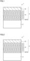
- FIG. 1 is a schematic enlarged cross section of a surface coated cutting tool according to an embodiment of the present invention.
- Fig. 2 is a schematic enlarged cross section of a surface coated cutting tool according to another embodiment of the present invention.
- Fig. 3 is a diagram for illustrating an example of a ratio in thickness of a first unit layer and a second unit layer.
- a surface coated cutting tool 1 includes a base material 2 and a coating layer 3 that coats base material 2.
- coating layer 3 coats the entire surface of base material 2.
- base material 2 is partially uncoated with coating layer 3 or coating layer 3 is partially different in configuration, such does not depart from the scope of the present invention.
- a surface coated cutting tool according to the present invention can suitably be used as a cutting tool such as drills, end mills, indexable cutting inserts for drills, indexable cutting inserts for end mills, indexable cutting inserts for milling, indexable cutting inserts for turning, metal saws, gear cutting tools, reamers, taps, and the like.
- Base material 2 used for surface coated cutting tool 1 of the present invention can be any base material conventionally known as a base material of this type.
- a cemented carbide for example, a WC-base cemented carbide or a material containing WC and in addition, Co, or a carbonitride of Ti, Ta, Nb, or the like added
- a cermet mainly composed of TiC, TiN, TiCN, or the like
- a high-speed steel a ceramic material (titanium carbide, silicon carbide, silicon nitride, aluminum nitride, aluminum oxide, and the like), a cubic crystal boron nitride sintered material, or a diamond sintered material, for example.
- a WC-base cemented carbide or a cermet a TiCN-base cermet, in particular.
- These base materials are particularly excellent in balance between hardness and strength at high temperature, and when they are used as a base material of a surface coated cutting tool, it can contribute to providing the surface coated cutting tool with a long lifetime.
- Coating layer 3 included in surface coated cutting tool 1 of the present invention includes an alternate layer 13 composed of first unit layer 12 and second unit layer 15 alternately stacked. Coating layer 3 can include another layer in addition to alternate layer 13.
- the other layer can for example be an underlying layer 16 (ZrAlN, ZrAlSiN, ZrAlBN, ZrAlVN, AlTiSiN, etc.), a front surface layer 14 (AlTiCN, AlTiSiCN, AlTiBCN, AlTiVCN, etc.) and the like.
- Coating layer 3 coats base material 2 to provide an effect to improve the surface coated cutting tool's various properties such as wear resistance and chipping resistance and increase its lifetime.
- the coating layer has an overall thickness of not less than 0.8 ⁇ m and not more than 15 ⁇ m. If the coating layer has an overall thickness of less than 0.8 ⁇ m, the coating layer is excessively small in thickness, and the surface coated cutting tool tends to have a short life. If it is thicker than 15 ⁇ m, the coating layer tends to chip in an initial stage cutting, and the surface coated cutting tool tends to have a short life.
- the coating layer's overall thickness can be determined by observing a cross section of the coating layer with a scanning electron microscope (SEM).
- a sample in cross section is observed with a magnification of 5,000 to 10,000 times in an area of 100 to 500 ⁇ m 2 , and in one field of view, three locations are subject to measurement in thickness in width and their average is determined as "thickness.” The same applies to the thickness of each layer described later unless otherwise specified.
- the coating layer preferably has compressive residual stress of not more than 6 GPa in absolute value.
- the coating layer's compressive residual stress is a type of internal stress (inherent strain) present throughout the coating layer, and refers to stress represented by a negative numerical value (in "GPa" in the present embodiment). Accordingly, the concept that compressive residual stress is large indicates that a numerical value is increased in absolute value, and the concept that compressive residual stress is small indicates that a numerical value is decreased in absolute value. That is, compressive residual stress having an absolute value of not more than 6 GPa means that a preferable residual stress for the coating layer is not less than - 6 GPa and not more than 0 GPa.
- the coating layer's residual stress exceeds 0 GPa, it will be a tensile stress, and the coating layer tends to be unable to suppress extension of a crack caused at an outermost surface of the coating layer. If the compressive residual stress has an absolute value exceeding 6 GPa, the stress is excessively large, and before cutting starts, the coating layer may be peeled off an edge of the surface coated cutting tool, in particular, and the surface coated cutting tool may have a reduced lifetime.
- the compressive residual stress can be measured in the sin 2 ⁇ method using an X-ray residual stress measuring apparatus (see “ X-Ray Stress Measurement,” The Society of Materials Science, Japan, 1981, Published by Yokendo Co., Ltd., pp. 54-66 ).
- the coating layer preferably has a cubic crystal structure.
- the coating layer is enhanced in hardness.
- each layer in the coating layer preferably has the cubic crystal structure.
- the crystal structure of the coating layer and each layer in the coating layer can be analyzed using an X-ray diffractometer known in the art.
- the coating layer preferably has a hardness of not less than 29 GPa and not more than 60 GPa, more preferably not less than 40 GPa and not more than 60 GPa. This allows the coating layer to have sufficient hardness.
- the coating layer's overall hardness can be measured in a nano indenter method (Nano Indenter XP manufactured by MTS). Specifically, the coating layer has a surface measured at three locations in hardness and an average value thereof is defined as "hardness.”
- the coating layer 3 includes alternate layer 13 composed of first unit layer 12 and second unit layer 15 alternately stacked.
- the first unit layer is composed of a nitride containing Al (aluminum) and Zr (zirconium), and when the total number of metal atoms constituting the first unit layer is represented as 1, a ratio thereto of the number of atoms of the Zr is not less than 0.65 and not more than 0.95.
- the second unit layer is composed of a nitride containing Ti (titanium) and Al, and when the total number of metal atoms constituting the second unit layer is represented as 1, a ratio thereto of the number of atoms of the Al is larger than 0.40 and not more than 0.70.
- a "metal atom” refers to an atom of an element other than hydrogen, helium, neon, argon, krypton, xenon, radon, fluorine, chlorine, bromine, iodine, astatine, oxygen, sulfur, selenium, tellurium, nitrogen, phosphorus, arsenic, antimony, and carbon.
- the composition of each layer including the first unit layer, the second unit layer, the underlying layer, an intermediate layer and the front surface layer, and a ratio of the number of atoms of each element (Zr, Al, Si, B, V) with respect to the total number of metal atoms in each layer can be measured with an X-ray photoelectron spectrometer (XPS).
- XPS X-ray photoelectron spectrometer
- a sample has a surface exposed to x-rays, and from the surface emits photoelectrons, and the photoelectrons' kinetic energy is measured to analyze the composition of an element constituting the surface of the sample and how the element is chemically bonded.
- the surface coated cutting tool according to the present invention exhibits an excellent effect, that is, can achieve a long life while processing a difficult-to-cut material. It is inferred that this is achieved for the following grounds (i) to (vi):
- the first unit layer is composed of a nitride containing Al and Zr.
- Zr's high melting point makes it difficult to maintain electric discharge and hence stably deposit the layer.
- the first unit layer contains Zr and, together therewith, Al having a low melting point, and accordingly, the first unit layer as a whole has a lowered melting point. As such, when the first unit layer is formed through physical vapor deposition, electric discharge is easily maintained and the layer can be stably deposited.
- the surface coated cutting tool of the present embodiment includes the coating layer composed of the first unit layer that contains Zr and the second unit layer that does not contain Zr, with the first and second unit layers alternately stacked, and the surface coated cutting tool can thus have a coating layer having a smaller Zr content than when the cutting tool has a coating layer formed of a single layer containing Zr. Therefore, it is also advantageous in terms of cost. Further, Zr is not contained in difficult-to-cut materials such as Inconel ® , and Zr in the first unit layer does not interdiffuse with a component in a workpiece during a process to accelerate damage to the coating layer.
- a ratio thereto of the number of atoms of the Zr is not less than 0.65 and not more than 0.95.
- the first unit layer will have a cubic crystal structure, and be increased in hardness and enhanced in wear resistance. If the ratio of the number of atoms of the Zr is less than 0.65, a part of the crystal structure becomes hexagonal, so that the first unit layer may be reduced in hardness and hence wear resistance. If the ratio of the number of atoms of the Zr is larger than 0.95, an effect by adding Al, that is, enhanced hardness, cannot be obtained, and the first unit layer would be reduced in hardness. From the viewpoint of further increasing the first unit layer in hardness, the ratio of the number of atoms of the Zr is preferably not less than 0.7 and not more than 0.85, and more preferably not less than 0.7 and not more than 0.8.
- the second unit layer is composed of a nitride containing Ti and Al.
- a layer containing Ti, Al and N has an excellent balance between wear resistance, oxidation resistance and toughness. The second unit layer can thus contribute to providing the surface coated cutting tool with a long life.
- the second unit layer When the total number of metal atoms constituting the second unit layer is represented as 1, a ratio thereto of the number of atoms of the Al is larger than 0.40 and not more than 0.70. In that case, the second unit layer will have a cubic crystal structure, and be increased in hardness and enhanced in wear resistance. If the ratio of the number of atoms of the Al exceeds 0.7, a part of the crystal structure becomes hexagonal, so that the second unit layer may be reduced in hardness and hence wear resistance. If the ratio of the number of atoms of the Al is less than 0.40, an effect by adding Al, that is, enhanced hardness, cannot be obtained, and the second unit layer would be reduced in hardness. From the viewpoint of further increasing the second unit layer in hardness, the ratio of the number of atoms of the Al is preferably not less than 0.55 and not more than 0.65, and more preferably not less than 0.6 and not more than 0.65.
- At least one of the first unit layer and the second unit layer can contain Si (silicon).
- Si silicon
- the first unit layer contains Si
- the total number of metal atoms constituting the first unit layer is represented as 1
- a ratio thereto of the number of atoms of the Si is preferably larger than 0 and not more than 0.20.
- the second unit layer contains Si
- a ratio thereto of the number of atoms of the Si is preferably larger than 0 and not more than 0.20.
- the layer containing Si is further increased in hardness and the coating layer as a whole is increased in hardness and also enhanced in oxidation resistance.
- the layer containing Si tends to become brittle, which accelerates wear. Furthermore, when a target made of an alloy serving as a source of metal for the layer containing Si is to be formed through a hot isostatic process, the target made of the alloy would be broken during baking, and it tends to be difficult to obtain material strength adequate for formation of the first or second unit layer.
- a ratio thereto of the number of atoms of the Si is preferably not less than 0.05 and not more than 0.15.
- At least one of the first unit layer and the second unit layer can contain B (boron).
- B boron
- the first unit layer contains B
- the total number of metal atoms constituting the first unit layer is represented as 1
- a ratio thereto of the number of atoms of the B is preferably larger than 0 and not more than 0.10.
- the second unit layer contains B
- the total number of metal atoms constituting the second unit layer is represented as 1
- a ratio thereto of the number of atoms of the B is preferably larger than 0 and not more than 0.10.
- the layer containing B is further increased in hardness and the coating layer as a whole is increased in hardness.
- an oxide of B formed by oxidation of a surface during cutting densifies an oxide of Al in the layer and hence enhances oxidation resistance.
- the oxide of B has a low melting point, it can act as a lubricant in cutting a workpiece and thus suppress adhesion of the workpiece.
- a ratio thereto of the number of atoms of the B is preferably not less than 0.05 and not more than 0.10.
- At least one of the first unit layer and the second unit layer can contain V (vanadium).
- V vanadium
- the first unit layer contains vanadium
- the total number of metal atoms constituting the first unit layer is represented as 1
- a ratio thereto of the number of atoms of the vanadium is preferably larger than 0 and not more than 0.30.
- the second unit layer contains vanadium
- the total number of metal atoms constituting the second unit layer is represented as 1
- a ratio thereto of the number of atoms of the vanadium is preferably larger than 0 and not more than 0.30.
- an oxide of V having a low melting point acts as a lubricant in the process, and can thus suppress adhesion of the workpiece.
- the layer containing V tends to be decreased in hardness. From the viewpoint of suppressing the adhesion of the workpiece and increasing in hardness the layer containing V, in the first and/or second unit layer, when the total number of metal atoms constituting the first or second unit layer is represented as 1, a ratio thereto of the number of atoms of the V is preferably larger than 0 and less than 0.15.
- the first unit layer and the second unit layer can include an inevitable impurity other than Al, Zr and N.
- the inevitable impurity includes oxygen, carbon or the like, for example.
- the first unit layer and the second unit layer preferably each contain inevitable impurity larger than 0 atomic% and less than 1 atomic% in total.
- "atomic %" refers to the percentage (%) of the number of atoms with respect to the total number of atoms constituting a layer. The percentage (%) of the number of atoms with respect to the total number of atoms constituting a layer can be measured using the above-described XPS analysis.
- the first unit layer and the second unit layer each have a thickness of not less than 0.002 ⁇ m and not more than 0.2 ⁇ m. This enables suppression of extension of cracking caused in a surface of the coating layer. If the first unit layer and the second unit layer each have a thickness of less than 0.002 ⁇ m, the layers will be mixed with each other, which tends to prevent achieving an effect by alternately stacking the first and second unit layers. If the first and second unit layers each have a thickness exceeding 0.2 ⁇ m, an effect to suppress extension of cracking tends to be obtained less likely. Preferably the first unit layer and the second unit layer each have a thickness of not less than 0.005 ⁇ m and not more than 0.15 ⁇ m.
- the first unit layer and the second unit layer when in the alternate layer the first unit layer and the second unit layer have a thickness ⁇ 1 and a thickness ⁇ 2, respectively, then, in the alternate layer the first unit layer and the second unit layer which are adjacent to each other have a ratio ⁇ 2/ ⁇ 1 of not less than 1 and not more than 5.
- the second unit layer has a high thermal conductivity and has a property to easily transfer heat generated during cutting to the base material. Accordingly, when the proportion of the second unit layer in the coating layer is relatively increased, the surface coated cutting tool as a whole provides improved heat dissipation and is thus enhanced in wear resistance during continuous cutting, in particular. If ⁇ 2/ ⁇ 1 is less than 1, the coating layer tends to be decreased in toughness. If ⁇ 2/ ⁇ 1 exceeds 5, an effect by stacking the first and second unit layers to suppress extension of cracking tends to be obtained less likely. From the viewpoint of balancing these characteristics, ⁇ 2/ ⁇ 1 is more preferably not less than 1 and less than 3.
- first unit layers and 10-500 second unit layers are stacked.
- first and second unit layers allow hardness and compressive residual stress to be improved in a good balance sufficiently effectively.
- the alternate layer preferably has an overall thickness of not less than 0.8 ⁇ m and not more than 15 ⁇ m, more preferably not less than 2 ⁇ m and not more than 7 ⁇ m.
- the thickness is less than 0.8 ⁇ m, there is a tendency to be unable to exhibit sufficient wear resistance in continuous processing, and when it exceeds 15 ⁇ m, chipping resistance tends to be unstable in interrupted cutting.
- the fact that in the alternate layer the first unit layer and the second unit layer are alternately stacked to form a multilayer structure can be confirmed as follows: a cross section of the coating layer is observed with a TEM (a transmission electron microscope) and when a difference in contrast is observed, it can be confirmed as indicating the multilayer structure.
- TEM transmission electron microscope
- the first unit layer's thickness, the second unit layer's thickness, how many first and second unit layers are stacked, and the alternate layer's thickness can be determined by observing a cross section of the coating layer with a TEM (a transmission electron microscope). Specifically, they can be determined as follows: a sliced sample is exposed to an electron beam and electrons transmitted through the sample or scattered by the sample are imaged and observed at high magnification.
- TEM transmission electron microscope
- coating layer 3 included in surface coated cutting tool 1 can include another layer in addition to alternate layer 13.
- the other layer can for example include underlying layer 16, front surface layer 14, and the like.
- coating layer 3 may further include an intermediate layer, an alumina layer or the like between alternate layer 13 and front surface layer 14.
- Coating layer 3 can include underlying layer 16 between base material 2 and coating layer 3 in order to increase adhesion between base material 2 and coating layer 3.
- Underlying layer 16 preferably has the same composition as first unit layer 12 or second unit layer 15.
- the underlying layer having the same composition as the first unit layer means that the underlying layer has the same composition as the first unit layer included in the alternate layer.
- the underlying layer is composed of a nitride containing Al and Zr, and when the total number of metal atoms constituting the underlying layer is represented as 1, a ratio thereto of the number of atoms of the Zr is not less than 0.65 and not more than 0.95.
- the underlying layer has the same composition as the first unit layer, and the base material is exposed in an initial stage of cutting, oxidation from the interface between the base material and the coating layer can be suppressed.
- the underlying layer having the same composition as the first unit layer can contain Si, B or V, and their contents can be equal to those of the first unit layer.
- a ratio thereto of the number of atoms of the Si is preferably larger than 0 and not more than 0.10. This allows the underlying layer to be increased in hardness and also have a fine crystal structure, and hence be increased in wear resistance.
- the underlying layer When the underlying layer has the same composition as the first unit layer, the underlying layer preferably has a thickness of not less than 0.1 ⁇ m. If the underlying layer has a thickness of less than 0.1 ⁇ m, there is a tendency to fail to obtain an effect by making the underlying layer have the same composition as the first unit layer to suppress oxidation caused from the interface between the base material and the coating layer. While the underlying layer has no particular upper limit value set for thickness, the underlying layer with a thickness exceeding 2 ⁇ m tends to be unable to further enhance the above oxidation suppressing effect. Therefore, when cost is considered the underlying layer preferably has a thickness of not more than 2 ⁇ m.
- the alternate layer may have the first unit layer stacked directly on the underlying layer having the same composition as the first unit layer (see Fig. 1 ), or may have the second unit layer stacked directly thereon.
- the underlying layer and the first unit layer of the alternate layer have a continuous crystal structure, and accordingly, will exist substantially as a layer composed of a single layer containing a nitride containing Al and Zr.
- the layer composed of a single layer of a nitride containing Al and Zr immediately above the base material is larger in thickness than another first unit layer in the alternate layer, it is understood that the underlying layer having the same composition as the first unit layer and the first unit layer of the alternate layer closest to the base material exist continuously. Furthermore, in that case, the thickness ⁇ 1 of the first unit layer described above is the thickness of a first unit layer other than the first unit layer immediately adjacent to the underlying layer.
- the underlying layer having the same composition as the second unit layer means that the underlying layer has the same composition as the second unit layer included in the alternate layer.
- the underlying layer is composed of a nitride containing Ti and Al, and when the total number of metal atoms constituting the underlying layer is represented as 1, a ratio thereto of the number of atoms of the Al is larger than 0.40 and not more than 0.70.
- the second unit layer tends to have a small stress, and the coating layer is significantly improved in resistance against peeling in interrupted processing, such as milling and end milling, in which the cutting edge repeatedly receives a load.
- a ratio thereto of the number of atoms of the Al is preferably larger than 0.50 and not more than 0.65.
- the underlying layer having the same composition as the second unit layer can contain Si, B or V, and their contents can be equal to those of the second unit layer.
- the underlying layer When the underlying layer has the same composition as the second unit layer, the underlying layer preferably has a thickness of not less than 0.1 ⁇ m. If the underlying layer has a thickness of less than 0.1 ⁇ m, there is a tendency to be unable to obtain an effect by making the underlying layer have the same composition as the second unit layer to enhance peeling resistance. While the underlying layer has no particular upper limit value set for thickness, the underlying layer with a thickness exceeding 2 ⁇ m tends not to be recognized to further enhance the above peeling resistance. Therefore, when cost is considered the underlying layer preferably has a thickness of not more than 2 ⁇ m.
- the alternate layer may have the first unit layer stacked directly on the underlying layer having the same composition as the second unit layer (see Fig. 2 ), or may have the second unit layer stacked directly thereon.
- the underlying layer and the second unit layer of the alternate layer have a continuous crystal structure, and accordingly, will exist substantially as a layer composed of a single layer containing a nitride containing Ti and Al.
- the layer composed of a single layer of a nitride containing Ti and Al immediately on the base material is larger in thickness than another second unit layer in the alternate layer, it is understood that the underlying layer having the same composition as the second unit layer and the second unit layer of the alternate layer closest to the base material exist continuously. Furthermore, in that case, the thickness ⁇ 2 of the second unit layer described above is the thickness of a second unit layer other than the second unit layer immediately adjacent to the underlying layer.
- Coating layer 3 can include front surface layer 14 on the side of the front surface of alternate layer 13 in order to reduce the coefficient of friction of coating layer 3 and extend the lifetime of the surface coated cutting tool.
- the front surface layer is composed of a carbonitride (a compound containing carbon and nitrogen) containing Ti and Al, and when the total number of metal atoms constituting the front surface layer is represented as 1, the ratio thereto of the number of atoms of the Al is preferably larger than 0.40 and not more than 0.60.
- a carbonitride tends to have a lower coefficient of friction with a workpiece than a nitride does. Such a smaller coefficient of friction is considered to be attributed to contribution of carbon atoms.
- the coating layer includes the front surface layer, the coating layer has a reduced coefficient of friction with a workpiece and the surface coated cutting tool has an extended lifetime.
- a carbonitride containing Ti and Al has excellent oxidation resistance.
- the front surface layer has a surface heated to a higher temperature than any other layer in a cutting process, the front surface layer that has excellent oxidation resistance allows the surface coated cutting tool to have an extended lifetime.
- the ratio thereto of the number of atoms of the Al is preferably not less than 0.50 and not more than 0.60.
- composition ratio of N and C in the front surface layer By adjusting the composition ratio of N and C in the front surface layer, a prescribed color can be imparted thereto. This allows the surface coated cutting tool to have an appearance with designability and distinctiveness commercially usefully.
- the front surface layer can contain Si, and when the total number of metal atoms constituting the front surface layer is represented as 1, a ratio thereto of the number of atoms of the Si is preferably larger than 0 and not more than 0.20, more preferably not less than 0.05 and not more than 0.15. This allows the front surface layer to be increased in hardness and also enhanced in oxidation resistance.
- the front surface layer can contain B and when the total number of metal atoms constituting the front surface layer is represented as 1, a ratio thereto of the number of atoms of the B is preferably larger than 0 and less than 0.10, more preferably larger than 0 and not more than 0.05. This allows the front surface layer to be increased in hardness. Further, an oxide of B formed by oxidation of a surface during cutting tends to densify an oxide of Al in the layer, which enhances oxidation resistance.
- the front surface layer can contain V and when the total number of metal atoms constituting the front surface layer is represented as 1, a ratio thereto of the number of atoms of the V is preferably larger than 0 and not more than 0.30, more preferably larger than 0 and less than 0.15. This can enhance the front surface layer in adhesion resistance.
- the front surface layer preferably has a thickness of not less than 0.1 ⁇ m. If the front surface layer has a thickness of less than 0.1 ⁇ m, an effect of the front surface layer to impart lubricity may not be easily obtained. While the front surface layer has no particular upper limit value set for thickness, the front surface layer with a thickness exceeding 2 ⁇ m tends to be unable to further enhance the above lubricity imparting effect. Therefore, when cost is considered the front surface layer preferably has a thickness of not more than 2 ⁇ m.
- a method for manufacturing a surface coated cutting tool according to one embodiment of the present invention described above includes: preparing a base material; and alternately stacking a first unit layer and a second unit layer on the base material through physical vapor deposition to form an alternate layer to obtain the surface coated cutting tool.
- the base material described above is prepared.
- PVD physical vapor deposition
- an underlying layer can be formed to enhance adhesion between the base material and the coating layer.
- cathodic arc ion plating As physical vapor deposition, at least one selected from the group consisting of cathodic arc ion plating, balanced magnetron sputtering and unbalanced magnetron sputtering, and HiPIMS can be used.
- cathodic arc ion plating is preferably used as it allows an element serving as a source material to be ionized at a high ratio.
- the base material can have a surface subjected to metal ion bombardment to achieve significantly enhanced adhesion of the base material and the coating layer including the alternate layer.
- Cathodic arc ion plating can be performed for example as follows: the base material is set in an apparatus and a target is also set as a cathode, and subsequently, a high voltage is applied to the target to cause arc discharge to ionize and evaporate the target's constituent atoms to deposit material on the base material.
- balanced magnetron sputtering can be performed for example as follows: a base material is set in an apparatus and a target is also set on a magnetron electrode provided with a magnet that forms a balanced magnetic field, and high-frequency power is applied between the magnetron electrode and the base material to generate a gas plasma, which generates a gas, and the gas's ions are caused to impinge on the target to release atoms therefrom to deposit the released atoms on the base material.
- Unbalanced magnetron sputtering can be performed for example by making unbalanced the magnetic field generated by the magnetron electrode in the balanced magnetron sputtering described above. Further, HiPIMS allowing high voltage to be applied and a dense film to be obtained can also be used.
- another layer such as an intermediate layer, an alumina layer, and a front surface layer, can be formed on the alternate layer.
- the other layer can be formed by chemical vapor deposition or physical vapor deposition as conventionally known.
- the other layer is preferably formed through physical vapor deposition from the viewpoint that the other layer can be formed with the first unit layer and the second unit layer in a single physical vapor deposition apparatus sequentially.
- Fig. 4 is a schematic cross section of a cathodic arc ion plating apparatus used in the present example
- Fig. 5 is a schematic top view of the apparatus shown in Fig. 4 .
- a cathode 106 for the first unit layer, a cathode 107 for the second unit layer, and a cathode 120 for the front surface layer, which are targets made of alloys serving as sources for metals for the coating layer, and a rotary-type base material holder 104 for placing base material 2 are set in a chamber 101.
- An arc power supply 108 is attached to cathode 106, and an arc power supply 109 is attached to cathode 107.
- a bias power supply 110 is attached to base material holder 104.
- chamber 101 Further provided to chamber 101 are a gas inlet through which gas 105 is introduced therein, and a gas outlet 103 for adjusting the pressure within chamber 101, and the gas in chamber 101 can be sucked by a vacuum pump via gas outlet 103.
- Base material 2 of a cemented carbide having a grade of JIS P30 and shaped according to JIS CNMG120408, and an insert of SEMT13T3AGSN manufactured by Sumitomo Electric Hardmetal Corp. were attached to base material holder 104.
- a vacuum pump was used to internally vacuum chamber 101, and while base material 2 was also rotated, a heater set in the apparatus was operated to raise temperature to 500°C, and chamber 101 was thus internally vacuumed to attain a pressure of 1.0 ⁇ 10 -4 Pa.
- gaseous argon was introduced via the gas inlet, and the pressure within chamber 101 was held at 3.0 Pa.
- the voltage of bias power supply 110 was gradually increased to - 1000 V, and base material 2 had a surface cleaned for 15 minutes.
- the gaseous argon was exhausted from chamber 101 to wash the base material (i.e., an argon bombardment treatment).
- cathodes 106 and 107 were each supplied with an arc current of 100 A and thus caused to generate metal ions to form an underlying layer and an alternate layer having the compositions shown in Table 1.
- cathode 106 had a composition adjusted to have Zr, Al, Si, B, and V at a ratio equal to that of a composition of the first unit layer indicated in Table 1.
- cathode 107 had a composition adjusted to have Al, Ti, Si, B, and V at a ratio equal to that of a composition of the second unit layer indicated in Table 1.
- the alternate layer was formed by stacking on the underlying layer the first unit layer and the second unit layer, one on the other alternately by the numbers of stacked layers indicated in Table 1. Further, the thickness of the underlying layer, that of each of the first and second unit layers in the alternate layer, and how many first and second unit layers were stacked were adjusted by the speed of rotation of the base material. A current supplied to an evaporation source was stopped when the underlying layer and the alternate layer each achieved a value in thickness indicated in Table 1.
- cathode 120 was supplied with an arc current of 100 A and thus caused to generate metal ions to form the front surface layer on the alternate layer.
- a current supplied to the evaporation source was stopped when the front surface layer achieved a value in thickness indicated in Table 1.
- cathode 120 had a composition adjusted to have Al, Ti, Si, B, and V at a ratio equal to that of a composition of the front surface layer indicated in Table 1.
- the ratio of nitrogen to carbon in the composition of the front surface layer was adjusted by the ratio of the amount of nitrogen introduced and the amount of methane gas introduced. Indexable cutting inserts of samples 1 to 3, 6 to 15, 17, 18, 21, 22, and 24 were thus produced.
- indexable cutting inserts of samples 4 and 5 were each fabricated as follows: on the same base material as sample 1, first and second unit layers each having a composition shown in Table 1 were alternately formed and furthermore, the front surface layer was formed, and the underlying layer was not formed.
- the indexable cutting insert of sample 16 was fabricated as follows: on the same base material as sample 1, first and second unit layers each having a composition shown in Table 1 were alternately formed and the underlying layer and the front surface layer were not formed.
- the indexable cutting insert of sample 19 was fabricated as follows: on the same base material as sample 1, a second unit layer having a composition shown in Table 1 was alone formed and the underlying layer, the first unit layer, and the front surface layer were not formed.
- indexable cutting inserts of samples 20 and 23 were each fabricated as follows: on the same base material as sample 1, an underlying layer having a composition shown in Table 1 was formed and first and second unit layers each having a composition shown in Table 1 were alternately formed, and the front surface layer was not formed.
- Table 1 underlying layer alternate layer ⁇ 2/ ⁇ 1 front surface layer coating layer as a whole 1st unit layer 2nd unit layer composition thickness composition thickness per layer no. of layers stacked thickness composition thickness per layer no. of layers stacked thickness composition thickness thickness hardness compressive residual stress crystallinity ( ⁇ m) ( ⁇ m) (no.) ( ⁇ m) ( ⁇ m) (no.) ( ⁇ m) ( ⁇ m) ( ⁇ m) (GPa) (GPa) sample 1 Zr 0.7 Al 0.3 N 0.5 Zr 0.7 Al 0.3 N 0.15 10 1.5 Al 0.6 Ti 0.4 N 0.15 10 1.5 1 Al 0.6 Ti 0.4 CN 0.5 4.0 49 2.1 cubic sample 2 Zr 0.7 Al 0.3 N 0.5 Zr 0.7 Al 0.3 N 0.05 30 1.5 Al 0.6 Ti 0.4 N 0.05 30 1.5 1 Al 0.6 Ti 0.4 N 0.05 30 1.5 1 Al 0.6 Ti 0.4 N 0.05 30 1.5 1 Al 0.6 Ti 0.4 N 0.05 30 1.5 1 Al 0.6 Ti 0.4 N 0.05 30 1.5 1 Al 0.6 Ti
- compositions of the underlying layer, the first unit layer, the second unit layer, and the front surface layer shown in Table 1 were measured using an XPS (X-ray photoelectron spectrometer).
- thickness per layer means the thickness of each one layer of the first and second unit layers configuring the alternate layer.
- thickness means a total thickness of each of the underlying layer, the first unit layer, the second unit layer, the front surface layer, and the coating layer.
- Thiickness per layer and thickness were values measured with a TEM and a SEM, respectively.
- no. of layers stacked refers to how many first unit layers are stacked in the alternate layer and how many second unit layers were stacked in the alternate layer.
- indexable cutting inserts of samples 1 to 24 having the CNMG120408 shape were each subjected to a wet continuous turning test and interrupted turning test to process alloy and difficult-to-cut material under the conditions shown in Table 2 to measure a period of time elapsing before the insert had a cutting edge with a flank worn by an amount of 0.2 mm.
- Table 3 A result is shown in Table 3.
- a longer cutting time indicates a longer lifetime.
- the indexable cutting inserts of samples 1 to 16 correspond to examples according to the present invention, and the indexable cutting inserts of samples 17 to 24 correspond to comparative examples.
- samples 1 to 16, 23 and 24 were compared with samples 17 to 22, the former had a cutting edge with a flank worn in a significantly reduced amount in both the continuous turning test and the interrupted turning test, and it has been confirmed that the former allows a difficult-to-cut material to be also processed fast and significantly efficiently while the indexable cutting insert has a significantly extended lifetime.
- the SEMT13T3AGSN-shaped indexable cutting inserts of samples 1 to 24 were each used, with a 150 mm-wide plate as a workpiece having a center line aligned with the center of a cutter of ⁇ 160 mm wider than the plate, to mill a surface under conditions for a dry milling test, as shown in Table 4, to measure a cut length achieved before the cutting edge had a flank worn by an amount of 0.2 mm.
- Table 5 A result is shown in Table 5.
- Table 5 a longer cut length indicates a longer lifetime.
- the indexable cutting inserts of samples 1 to 16 correspond to examples according to the present invention, and the indexable cutting inserts of samples 17 to 24 correspond to comparative examples.
- samples 1 to 16, 23, and 24 are compared with samples 17 to 22, the former allows a cutting edge to provide a significantly increased cut length, and it has been confirmed that the former also allows fast and highly efficient, dry milling to be performed while the indexable cutting insert has a significantly extended lifetime.
- 1 surface coated cutting tool 1 base material, 3 coating layer, 12 first unit layer, 13 alternate layer, 14 front surface layer, 15 second unit layer, 16 underlying layer, 101 chamber, 103 gas outlet, 104 base material holder, 105 gas, 106, 107, 120 cathode, 108, 109 arc power supply, 110 bias power supply.
Landscapes
- Chemical & Material Sciences (AREA)
- Engineering & Computer Science (AREA)
- Mechanical Engineering (AREA)
- Chemical Kinetics & Catalysis (AREA)
- Materials Engineering (AREA)
- Metallurgy (AREA)
- Organic Chemistry (AREA)
- Inorganic Chemistry (AREA)
- Cutting Tools, Boring Holders, And Turrets (AREA)
- Drilling Tools (AREA)
- Physical Vapour Deposition (AREA)
Claims (13)
- Oberflächenbeschichtetes Schneidwerkzeug (1), das ein Basismaterial (2) und eine auf dem Basismaterial (2) angeordnete Beschichtung( 3) umfasst,wobei die Beschichtung (3) eine abwechselnde Schicht (13) enthält, die aus einer ersten Einheitsschicht (12) und einer zweiten Einheitsschicht (15) besteht, die abwechselnd gestapelt sind, wobei die erste Einheitsschicht (12) und die zweite Einheitsschicht (15) in der abwechselnden Schicht (13) zueinander benachbart sind,wobei die erste Einheitsschicht (12) aus einem Nitrid besteht, das Aluminium und Zirkonium enthält,wobei in der ersten Einheitsschicht (12), wenn die Gesamtzahl der Metallatome, die die erste Einheitsschicht (12) bilden, als 1 dargestellt wird, ein Verhältnis der Anzahl der Zirkoniumatome zu dieser nicht weniger als 0,65 und nicht mehr als 0,95 beträgt,die Beschichtung (3) eine Gesamtdicke von nicht weniger als 0,8 µm und nicht mehr als 15 µm aufweist,die erste Einheitsschicht (12) und die zweite Einheitsschicht (15) jeweils eine Dicke von nicht weniger als 0,002 µm und nicht mehr als 0,2 µm aufweisen,wenn in der abwechselnden Schicht (13) die erste Einheitsschicht (12) und die zweite Einheitsschicht (15), die zueinander benachbart sind, eine Dicke λ1 bzw. eine Dicke λ2 aufweisen, wobei das Verhältnis λ2/λ1 nicht weniger als 1 und nicht mehr als 5 beträgt,10 bis 500 erste Einheitsschichten (12) und 10 bis 500 zweite Einheitsschichten (15) gestapelt sind,wobei die zweiten Einheitsschichten (15) aus einem Nitrid besteht, das Titan und Aluminium enthält, undwobei in der zweiten Einheitsschicht (15), wenn die Gesamtzahl der Metallatome, die die zweite Einheitsschicht (15) bilden, als 1 dargestellt wird, ein Verhältnis der Anzahl der Aluminiumatome zu dieser größer als 0,40 und nicht mehr als 0,70 ist.
- Oberflächenbeschichtetes Schneidwerkzeug (1) nach Anspruch 1, wobei
das Verhältnis λ2/λ1 nicht kleiner als 1 und kleiner als 3 ist. - Oberflächenbeschichtetes Schneidwerkzeug (1) nach Anspruch 1 oder 2, wobeidie erste Einheitsschicht (12) Silizium enthält, undin der ersten Einheitsschicht (12), wenn die Gesamtzahl der Metallatome, die die erste Einheitsschicht (12) bilden, als 1 dargestellt wird, ein Verhältnis der Anzahl der Siliziumatome zu dieser größer als 0 und nicht mehr als 0,20 ist.
- Oberflächenbeschichtetes Schneidwerkzeug (1) nach einem der Ansprüche 1 bis 3, wobeidie zweite Einheitsschicht (15) Silizium enthält, undin der zweiten Einheitsschicht (15), wenn die Gesamtzahl der Metallatome, die die zweite Einheitsschicht (15) bilden, als 1 dargestellt wird, ein Verhältnis der Anzahl der Siliziumatome zu dieser größer als 0 und nicht mehr als 0,20 ist.
- Oberflächenbeschichtetes Schneidwerkzeug (1) nach einem der Ansprüche 1 bis 4, wobeidie erste Einheitsschicht (12) Bor enthält, undin der ersten Einheitsschicht (12), wenn die Gesamtzahl der Metallatome, die die erste Einheitsschicht (12) bilden, als 1 dargestellt wird, ein Verhältnis der Anzahl der Boratome zu dieser größer als 0 und nicht mehr als 0,10 ist.
- Oberflächenbeschichtetes Schneidwerkzeug (1) nach einem der Ansprüche 1 bis 5, wobeidie zweite Einheitsschicht (15) Bor enthält, undin der zweiten Einheitsschicht (15), wenn die Gesamtzahl der Metallatome, die die zweite Einheitsschicht (15) bilden, als 1 dargestellt wird, ein Verhältnis der Anzahl der Boratome zu dieser größer als 0 und nicht mehr als 0,10 ist,
- Oberflächenbeschichtetes Schneidwerkzeug (1) nach einem der Ansprüche 1 bis 6, wobeidie erste Einheitsschicht (12) Vanadium enthält, undin der ersten Einheitsschicht (12), wenn die Gesamtzahl der Metallatome, die die erste Einheitsschicht bilden, als 1 dargestellt wird, ein Verhältnis der Anzahl der Vanadiumatome zu dieser größer als 0 und nicht mehr als 0,30 ist.
- Oberflächenbeschichtetes Schneidwerkzeug (1) nach einem der Ansprüche 1 bis 7, wobeidie zweite Einheitsschicht (15) Vanadium enthält, undin der zweiten Einheitsschicht (15), wenn die Gesamtzahl der Metallatome, die die zweite Einheitsschicht (15) bilden, als 1 dargestellt wird, ein Verhältnis der Anzahl der Vanadiumatome zu dieser größer als 0 und nicht mehr als 0,30 ist.
- Oberflächenbeschichtetes Schneidwerkzeug (1) nach einem der Ansprüche 1 bis 8, wobeidie Beschichtung (3) eine darunter liegende Schicht (16) beinhaltet, die zwischen dem Basismaterial (2) und der abwechselnden Schicht (13) angeordnet ist, unddie darunter liegende Schicht (16) eine Zusammensetzung aufweist, die mit derjenigen der ersten Einheitsschicht (12) oder der zweiten Einheitsschicht (15) identisch ist.
- Oberflächenbeschichtetes Schneidwerkzeug (1) nach einem der Ansprüche 1 bis 9, wobeidie Beschichtung (3) eine vordere Oberflächenschicht (14) aufweist, die auf einer Seite einer vorderen Oberfläche der abwechselnden Schicht (13) angeordnet ist,wobei die vordere Oberflächenschicht (14) aus einem Carbonitrid besteht, das Titan und Aluminium enthält, undwobei in der vorderen Oberflächenschicht (14), wenn die Gesamtzahl der Metallatome, die die vordere Oberflächenschicht (14) bilden, als 1 dargestellt wird, ein Verhältnis der Anzahl der Aluminiumatome zu dieser größer als 0,40 und nicht mehr als 0,60 ist.
- Oberflächenbeschichtetes Schneidwerkzeug (1) nach einem der Ansprüche 1 bis 10, wobei
die Beschichtung (3) eine Druckeigenspannung von nicht mehr als 6 GPa in absoluten Werten aufweist. - Oberflächenbeschichtetes Schneidwerkzeug (1) nach einem der Ansprüche 1 bis 11, wobei
die Beschichtung (3) eine kubische Kristallstruktur aufweist. - Verfahren zur Herstellung eines oberflächenbeschichteten Schneidwerkzeugs (1) nach einem der Ansprüche 1 bis 12, umfassend:Herstellen des Basismaterials (2); undabwechselndes Stapeln der ersten Einheitsschicht (12) und der zweiten Einheitsschicht (15) auf dem Basismaterial (2) durch Vakuumaufdampfen, um die abwechselnde Schicht (13) auf dem Basismaterial (2) zu bilden und das oberflächenbeschichtete Schneidwerkzeug (1) zu erhalten.
Applications Claiming Priority (2)
| Application Number | Priority Date | Filing Date | Title |
|---|---|---|---|
| JP2018040874 | 2018-03-07 | ||
| PCT/JP2018/038491 WO2019171648A1 (ja) | 2018-03-07 | 2018-10-16 | 表面被覆切削工具及びその製造方法 |
Publications (3)
| Publication Number | Publication Date |
|---|---|
| EP3763465A1 EP3763465A1 (de) | 2021-01-13 |
| EP3763465A4 EP3763465A4 (de) | 2021-08-04 |
| EP3763465B1 true EP3763465B1 (de) | 2024-11-06 |
Family
ID=67847004
Family Applications (1)
| Application Number | Title | Priority Date | Filing Date |
|---|---|---|---|
| EP18908401.5A Active EP3763465B1 (de) | 2018-03-07 | 2018-10-16 | Oberflächenbeschichtetes schneidwerkzeug und verfahren zur herstellung davon |
Country Status (5)
| Country | Link |
|---|---|
| US (1) | US11298748B2 (de) |
| EP (1) | EP3763465B1 (de) |
| JP (1) | JP7067689B2 (de) |
| CN (1) | CN111587157B (de) |
| WO (1) | WO2019171648A1 (de) |
Families Citing this family (6)
| Publication number | Priority date | Publication date | Assignee | Title |
|---|---|---|---|---|
| JP7055961B2 (ja) * | 2018-10-03 | 2022-04-19 | 住友電工ハードメタル株式会社 | 表面被覆切削工具及びその製造方法 |
| WO2020075698A1 (ja) * | 2018-10-11 | 2020-04-16 | 株式会社不二越 | 硬質皮膜被覆ドリル |
| JP7570599B2 (ja) * | 2021-03-17 | 2024-10-22 | 三菱マテリアル株式会社 | 表面被覆切削工具 |
| EP4386110A1 (de) * | 2022-12-16 | 2024-06-19 | AB Sandvik Coromant | Beschichtetes schneidwerkzeug |
| CN116288184B (zh) * | 2023-02-24 | 2025-08-15 | 厦门钨业股份有限公司 | 纳米多层复合涂层及其制备方法和切削工具 |
| CN116180023B (zh) * | 2023-02-24 | 2025-06-13 | 厦门钨业股份有限公司 | 纳米多层结构涂层及其制备方法和应用 |
Citations (5)
| Publication number | Priority date | Publication date | Assignee | Title |
|---|---|---|---|---|
| WO2006070730A1 (ja) * | 2004-12-28 | 2006-07-06 | Sumitomo Electric Hardmetal Corp. | 表面被覆切削工具および表面被覆切削工具の製造方法 |
| US20090060669A1 (en) * | 2007-09-05 | 2009-03-05 | Sandvik Intellectual Property Ab | Coated drill and a method of making the same |
| US20100044969A1 (en) * | 2006-10-04 | 2010-02-25 | Manfred Fischer | Piston ring for internal combustion engines |
| US20120282049A1 (en) * | 2010-11-10 | 2012-11-08 | Sumitomo Electric Hardmetal Corp. | Surface-coated cutting tool |
| EP3017896A1 (de) * | 2013-07-03 | 2016-05-11 | Sumitomo Electric Hardmetal Corp. | Oberflächenbeschichtetes bornitrid-sinterwerkzeug |
Family Cites Families (22)
| Publication number | Priority date | Publication date | Assignee | Title |
|---|---|---|---|---|
| JP4062583B2 (ja) | 2001-07-23 | 2008-03-19 | 株式会社神戸製鋼所 | 切削工具用硬質皮膜およびその製造方法並びに硬質皮膜形成用ターゲット |
| JP4062582B2 (ja) * | 2001-07-23 | 2008-03-19 | 株式会社神戸製鋼所 | 切削工具用硬質皮膜およびその製造方法並びに硬質皮膜形成用ターゲット |
| DE10233222B4 (de) | 2001-07-23 | 2007-03-01 | Kabushiki Kaisha Kobe Seiko Sho (Kobe Steel, Ltd.), Kobe | Harte verschleissfeste Schicht, Verfahren zum Bilden derselben und Verwendung |
| SE526336C2 (sv) * | 2002-07-01 | 2005-08-23 | Seco Tools Ab | Skär med slitstark refraktär beläggning av MAX-fas |
| JP4367032B2 (ja) * | 2003-07-09 | 2009-11-18 | 三菱マテリアル株式会社 | 高速切削加工で硬質被覆層がすぐれた耐摩耗性を発揮する表面被覆超硬合金製切削工具 |
| JP3934136B2 (ja) * | 2004-11-11 | 2007-06-20 | 日立ツール株式会社 | 硬質皮膜被覆部材及びその被覆方法 |
| WO2006070509A1 (ja) * | 2004-12-28 | 2006-07-06 | Sumitomo Electric Hardmetal Corp. | 表面被覆切削工具および表面被覆切削工具の製造方法 |
| JP4939032B2 (ja) | 2005-02-08 | 2012-05-23 | 株式会社神戸製鋼所 | 硬質皮膜、および硬質皮膜の製造方法 |
| CN100529157C (zh) | 2005-02-08 | 2009-08-19 | 株式会社神户制钢所 | 硬涂层,形成硬涂层用的靶和形成硬涂层的方法 |
| JP4645819B2 (ja) | 2005-04-04 | 2011-03-09 | 三菱マテリアル株式会社 | 高硬度鋼の高速切削加工で硬質被覆層がすぐれた耐摩耗性を発揮する表面被覆超硬合金製切削工具 |
| JP4697660B2 (ja) | 2005-06-28 | 2011-06-08 | 三菱マテリアル株式会社 | 高硬度鋼の高速切削加工で硬質被覆層がすぐれた耐摩耗性を発揮する表面被覆切削工具 |
| JP5138892B2 (ja) * | 2006-01-20 | 2013-02-06 | 株式会社神戸製鋼所 | 硬質皮膜 |
| JP5446412B2 (ja) | 2009-04-15 | 2014-03-19 | 株式会社タンガロイ | 被覆cBN焼結体 |
| JP5093530B2 (ja) | 2010-03-31 | 2012-12-12 | 住友電工ハードメタル株式会社 | 表面被覆切削工具 |
| EP2628826A1 (de) | 2012-02-14 | 2013-08-21 | Sandvik Intellectual Property AB | Beschichtetes Schneidwerkzeug und Herstellungsverfahren dafür |
| EP2636764B1 (de) * | 2012-03-07 | 2014-07-09 | Seco Tools Ab | Nanolaminiertes und beschichtetes Schneidewerkzeug |
| DE102012017731A1 (de) * | 2012-09-08 | 2014-03-13 | Oerlikon Trading Ag, Trübbach | Ti-Al-Ta-basierte Beschichtung mit einer verbesserten Temperaturbeständigkeit |
| US10583493B2 (en) | 2015-04-27 | 2020-03-10 | Tungaloy Corporation | Coated cutting tool |
| JP2016211052A (ja) | 2015-05-12 | 2016-12-15 | 株式会社神戸製鋼所 | 硬質皮膜および硬質皮膜被覆部材 |
| KR101753104B1 (ko) | 2015-09-18 | 2017-07-05 | 한국야금 주식회사 | 절삭공구용 경질피막 |
| US10737332B2 (en) * | 2016-04-07 | 2020-08-11 | Tungaloy Corporation | Coated cutting tool |
| JP6887771B2 (ja) | 2016-09-06 | 2021-06-16 | キヤノン株式会社 | 画像形成装置 |
-
2018
- 2018-10-16 JP JP2020504768A patent/JP7067689B2/ja active Active
- 2018-10-16 CN CN201880084647.3A patent/CN111587157B/zh active Active
- 2018-10-16 US US16/958,183 patent/US11298748B2/en active Active
- 2018-10-16 WO PCT/JP2018/038491 patent/WO2019171648A1/ja not_active Ceased
- 2018-10-16 EP EP18908401.5A patent/EP3763465B1/de active Active
Patent Citations (5)
| Publication number | Priority date | Publication date | Assignee | Title |
|---|---|---|---|---|
| WO2006070730A1 (ja) * | 2004-12-28 | 2006-07-06 | Sumitomo Electric Hardmetal Corp. | 表面被覆切削工具および表面被覆切削工具の製造方法 |
| US20100044969A1 (en) * | 2006-10-04 | 2010-02-25 | Manfred Fischer | Piston ring for internal combustion engines |
| US20090060669A1 (en) * | 2007-09-05 | 2009-03-05 | Sandvik Intellectual Property Ab | Coated drill and a method of making the same |
| US20120282049A1 (en) * | 2010-11-10 | 2012-11-08 | Sumitomo Electric Hardmetal Corp. | Surface-coated cutting tool |
| EP3017896A1 (de) * | 2013-07-03 | 2016-05-11 | Sumitomo Electric Hardmetal Corp. | Oberflächenbeschichtetes bornitrid-sinterwerkzeug |
Also Published As
| Publication number | Publication date |
|---|---|
| JPWO2019171648A1 (ja) | 2020-12-17 |
| JP7067689B2 (ja) | 2022-05-16 |
| WO2019171648A1 (ja) | 2019-09-12 |
| EP3763465A4 (de) | 2021-08-04 |
| CN111587157B (zh) | 2023-06-20 |
| US11298748B2 (en) | 2022-04-12 |
| CN111587157A (zh) | 2020-08-25 |
| EP3763465A1 (de) | 2021-01-13 |
| US20210069794A1 (en) | 2021-03-11 |
Similar Documents
| Publication | Publication Date | Title |
|---|---|---|
| EP3153259B1 (de) | Oberflächenbeschichtetes werkzeug und verfahren zur herstellung davon | |
| EP3763465B1 (de) | Oberflächenbeschichtetes schneidwerkzeug und verfahren zur herstellung davon | |
| EP3269479A1 (de) | Oberflächenbeschichtetes schneidwerkzeug und herstellungsverfahren dafür | |
| EP3763466B1 (de) | Oberflächenbeschichtetes schneidwerkzeug und verfahren zur herstellung davon | |
| JP7055961B2 (ja) | 表面被覆切削工具及びその製造方法 | |
| EP4501504A1 (de) | Schneidwerkzeug | |
| EP4501503A1 (de) | Schneidwerkzeug | |
| EP4434656B1 (de) | Schneidwerkzeug | |
| US12186812B2 (en) | Cutting tool | |
| EP4582200A1 (de) | Schneidwerkzeug | |
| EP4588596A1 (de) | Schneidwerkzeug | |
| EP4703071A1 (de) | Schneidwerkzeug | |
| EP4506089A1 (de) | Schneidwerkzeug | |
| EP4450195A1 (de) | Schneidwerkzeug | |
| EP4434657A1 (de) | Schneidwerkzeug | |
| EP4527526A1 (de) | Schneidwerkzeug | |
| EP4400236A1 (de) | Schneidwerkzeug |
Legal Events
| Date | Code | Title | Description |
|---|---|---|---|
| STAA | Information on the status of an ep patent application or granted ep patent |
Free format text: STATUS: THE INTERNATIONAL PUBLICATION HAS BEEN MADE |
|
| PUAI | Public reference made under article 153(3) epc to a published international application that has entered the european phase |
Free format text: ORIGINAL CODE: 0009012 |
|
| STAA | Information on the status of an ep patent application or granted ep patent |
Free format text: STATUS: REQUEST FOR EXAMINATION WAS MADE |
|
| 17P | Request for examination filed |
Effective date: 20200625 |
|
| AK | Designated contracting states |
Kind code of ref document: A1 Designated state(s): AL AT BE BG CH CY CZ DE DK EE ES FI FR GB GR HR HU IE IS IT LI LT LU LV MC MK MT NL NO PL PT RO RS SE SI SK SM TR |
|
| AX | Request for extension of the european patent |
Extension state: BA ME |
|
| DAV | Request for validation of the european patent (deleted) | ||
| DAX | Request for extension of the european patent (deleted) | ||
| A4 | Supplementary search report drawn up and despatched |
Effective date: 20210707 |
|
| RIC1 | Information provided on ipc code assigned before grant |
Ipc: B23B 27/14 20060101AFI20210701BHEP Ipc: B23B 51/00 20060101ALI20210701BHEP Ipc: B23C 5/16 20060101ALI20210701BHEP Ipc: B23D 77/00 20060101ALI20210701BHEP Ipc: B23F 21/00 20060101ALI20210701BHEP Ipc: B23G 5/06 20060101ALI20210701BHEP Ipc: C23C 14/06 20060101ALI20210701BHEP Ipc: C23C 28/04 20060101ALI20210701BHEP Ipc: C23C 14/16 20060101ALI20210701BHEP Ipc: C23C 28/00 20060101ALI20210701BHEP Ipc: C23C 30/00 20060101ALI20210701BHEP Ipc: C23C 14/00 20060101ALI20210701BHEP Ipc: C23C 14/32 20060101ALI20210701BHEP Ipc: C23C 14/02 20060101ALI20210701BHEP |
|
| GRAP | Despatch of communication of intention to grant a patent |
Free format text: ORIGINAL CODE: EPIDOSNIGR1 |
|
| STAA | Information on the status of an ep patent application or granted ep patent |
Free format text: STATUS: GRANT OF PATENT IS INTENDED |
|
| INTG | Intention to grant announced |
Effective date: 20240325 |
|
| GRAJ | Information related to disapproval of communication of intention to grant by the applicant or resumption of examination proceedings by the epo deleted |
Free format text: ORIGINAL CODE: EPIDOSDIGR1 |
|
| STAA | Information on the status of an ep patent application or granted ep patent |
Free format text: STATUS: REQUEST FOR EXAMINATION WAS MADE |
|
| GRAP | Despatch of communication of intention to grant a patent |
Free format text: ORIGINAL CODE: EPIDOSNIGR1 |
|
| STAA | Information on the status of an ep patent application or granted ep patent |
Free format text: STATUS: GRANT OF PATENT IS INTENDED |
|
| INTC | Intention to grant announced (deleted) | ||
| INTG | Intention to grant announced |
Effective date: 20240606 |
|
| GRAS | Grant fee paid |
Free format text: ORIGINAL CODE: EPIDOSNIGR3 |
|
| GRAA | (expected) grant |
Free format text: ORIGINAL CODE: 0009210 |
|
| STAA | Information on the status of an ep patent application or granted ep patent |
Free format text: STATUS: THE PATENT HAS BEEN GRANTED |
|
| AK | Designated contracting states |
Kind code of ref document: B1 Designated state(s): AL AT BE BG CH CY CZ DE DK EE ES FI FR GB GR HR HU IE IS IT LI LT LU LV MC MK MT NL NO PL PT RO RS SE SI SK SM TR |
|
| REG | Reference to a national code |
Ref country code: GB Ref legal event code: FG4D |
|
| P01 | Opt-out of the competence of the unified patent court (upc) registered |
Free format text: CASE NUMBER: APP_54246/2024 Effective date: 20241004 |
|
| REG | Reference to a national code |
Ref country code: CH Ref legal event code: EP |
|
| REG | Reference to a national code |
Ref country code: DE Ref legal event code: R096 Ref document number: 602018076423 Country of ref document: DE |
|
| REG | Reference to a national code |
Ref country code: IE Ref legal event code: FG4D |
|
| REG | Reference to a national code |
Ref country code: SE Ref legal event code: TRGR |
|
| REG | Reference to a national code |
Ref country code: LT Ref legal event code: MG9D |
|
| REG | Reference to a national code |
Ref country code: NL Ref legal event code: MP Effective date: 20241106 |
|
| PG25 | Lapsed in a contracting state [announced via postgrant information from national office to epo] |
Ref country code: HR Free format text: LAPSE BECAUSE OF FAILURE TO SUBMIT A TRANSLATION OF THE DESCRIPTION OR TO PAY THE FEE WITHIN THE PRESCRIBED TIME-LIMIT Effective date: 20241106 Ref country code: PT Free format text: LAPSE BECAUSE OF FAILURE TO SUBMIT A TRANSLATION OF THE DESCRIPTION OR TO PAY THE FEE WITHIN THE PRESCRIBED TIME-LIMIT Effective date: 20250306 Ref country code: IS Free format text: LAPSE BECAUSE OF FAILURE TO SUBMIT A TRANSLATION OF THE DESCRIPTION OR TO PAY THE FEE WITHIN THE PRESCRIBED TIME-LIMIT Effective date: 20250306 |
|
| PG25 | Lapsed in a contracting state [announced via postgrant information from national office to epo] |
Ref country code: NL Free format text: LAPSE BECAUSE OF FAILURE TO SUBMIT A TRANSLATION OF THE DESCRIPTION OR TO PAY THE FEE WITHIN THE PRESCRIBED TIME-LIMIT Effective date: 20241106 Ref country code: FI Free format text: LAPSE BECAUSE OF FAILURE TO SUBMIT A TRANSLATION OF THE DESCRIPTION OR TO PAY THE FEE WITHIN THE PRESCRIBED TIME-LIMIT Effective date: 20241106 |
|
| REG | Reference to a national code |
Ref country code: AT Ref legal event code: MK05 Ref document number: 1738830 Country of ref document: AT Kind code of ref document: T Effective date: 20241106 |
|
| PG25 | Lapsed in a contracting state [announced via postgrant information from national office to epo] |
Ref country code: BG Free format text: LAPSE BECAUSE OF FAILURE TO SUBMIT A TRANSLATION OF THE DESCRIPTION OR TO PAY THE FEE WITHIN THE PRESCRIBED TIME-LIMIT Effective date: 20241106 |
|
| PG25 | Lapsed in a contracting state [announced via postgrant information from national office to epo] |
Ref country code: ES Free format text: LAPSE BECAUSE OF FAILURE TO SUBMIT A TRANSLATION OF THE DESCRIPTION OR TO PAY THE FEE WITHIN THE PRESCRIBED TIME-LIMIT Effective date: 20241106 |
|
| PG25 | Lapsed in a contracting state [announced via postgrant information from national office to epo] |
Ref country code: NO Free format text: LAPSE BECAUSE OF FAILURE TO SUBMIT A TRANSLATION OF THE DESCRIPTION OR TO PAY THE FEE WITHIN THE PRESCRIBED TIME-LIMIT Effective date: 20250206 |
|
| PG25 | Lapsed in a contracting state [announced via postgrant information from national office to epo] |
Ref country code: GR Free format text: LAPSE BECAUSE OF FAILURE TO SUBMIT A TRANSLATION OF THE DESCRIPTION OR TO PAY THE FEE WITHIN THE PRESCRIBED TIME-LIMIT Effective date: 20250207 Ref country code: LV Free format text: LAPSE BECAUSE OF FAILURE TO SUBMIT A TRANSLATION OF THE DESCRIPTION OR TO PAY THE FEE WITHIN THE PRESCRIBED TIME-LIMIT Effective date: 20241106 Ref country code: AT Free format text: LAPSE BECAUSE OF FAILURE TO SUBMIT A TRANSLATION OF THE DESCRIPTION OR TO PAY THE FEE WITHIN THE PRESCRIBED TIME-LIMIT Effective date: 20241106 |
|
| PG25 | Lapsed in a contracting state [announced via postgrant information from national office to epo] |
Ref country code: PL Free format text: LAPSE BECAUSE OF FAILURE TO SUBMIT A TRANSLATION OF THE DESCRIPTION OR TO PAY THE FEE WITHIN THE PRESCRIBED TIME-LIMIT Effective date: 20241106 |
|
| PG25 | Lapsed in a contracting state [announced via postgrant information from national office to epo] |
Ref country code: RS Free format text: LAPSE BECAUSE OF FAILURE TO SUBMIT A TRANSLATION OF THE DESCRIPTION OR TO PAY THE FEE WITHIN THE PRESCRIBED TIME-LIMIT Effective date: 20250206 |
|
| PG25 | Lapsed in a contracting state [announced via postgrant information from national office to epo] |
Ref country code: SM Free format text: LAPSE BECAUSE OF FAILURE TO SUBMIT A TRANSLATION OF THE DESCRIPTION OR TO PAY THE FEE WITHIN THE PRESCRIBED TIME-LIMIT Effective date: 20241106 |
|
| PG25 | Lapsed in a contracting state [announced via postgrant information from national office to epo] |
Ref country code: DK Free format text: LAPSE BECAUSE OF FAILURE TO SUBMIT A TRANSLATION OF THE DESCRIPTION OR TO PAY THE FEE WITHIN THE PRESCRIBED TIME-LIMIT Effective date: 20241106 |
|
| PG25 | Lapsed in a contracting state [announced via postgrant information from national office to epo] |
Ref country code: EE Free format text: LAPSE BECAUSE OF FAILURE TO SUBMIT A TRANSLATION OF THE DESCRIPTION OR TO PAY THE FEE WITHIN THE PRESCRIBED TIME-LIMIT Effective date: 20241106 |
|
| PG25 | Lapsed in a contracting state [announced via postgrant information from national office to epo] |
Ref country code: RO Free format text: LAPSE BECAUSE OF FAILURE TO SUBMIT A TRANSLATION OF THE DESCRIPTION OR TO PAY THE FEE WITHIN THE PRESCRIBED TIME-LIMIT Effective date: 20241106 |
|
| PG25 | Lapsed in a contracting state [announced via postgrant information from national office to epo] |
Ref country code: SK Free format text: LAPSE BECAUSE OF FAILURE TO SUBMIT A TRANSLATION OF THE DESCRIPTION OR TO PAY THE FEE WITHIN THE PRESCRIBED TIME-LIMIT Effective date: 20241106 |
|
| PG25 | Lapsed in a contracting state [announced via postgrant information from national office to epo] |
Ref country code: CZ Free format text: LAPSE BECAUSE OF FAILURE TO SUBMIT A TRANSLATION OF THE DESCRIPTION OR TO PAY THE FEE WITHIN THE PRESCRIBED TIME-LIMIT Effective date: 20241106 |
|
| PG25 | Lapsed in a contracting state [announced via postgrant information from national office to epo] |
Ref country code: IT Free format text: LAPSE BECAUSE OF FAILURE TO SUBMIT A TRANSLATION OF THE DESCRIPTION OR TO PAY THE FEE WITHIN THE PRESCRIBED TIME-LIMIT Effective date: 20241106 |
|
| REG | Reference to a national code |
Ref country code: DE Ref legal event code: R097 Ref document number: 602018076423 Country of ref document: DE |
|
| PLBE | No opposition filed within time limit |
Free format text: ORIGINAL CODE: 0009261 |
|
| STAA | Information on the status of an ep patent application or granted ep patent |
Free format text: STATUS: NO OPPOSITION FILED WITHIN TIME LIMIT |
|
| 26N | No opposition filed |
Effective date: 20250807 |
|
| PGFP | Annual fee paid to national office [announced via postgrant information from national office to epo] |
Ref country code: SE Payment date: 20250910 Year of fee payment: 8 |
|
| PGFP | Annual fee paid to national office [announced via postgrant information from national office to epo] |
Ref country code: DE Payment date: 20250902 Year of fee payment: 8 |