EP3763468B1 - Fräswerkzeug - Google Patents
Fräswerkzeug Download PDFInfo
- Publication number
- EP3763468B1 EP3763468B1 EP20181009.0A EP20181009A EP3763468B1 EP 3763468 B1 EP3763468 B1 EP 3763468B1 EP 20181009 A EP20181009 A EP 20181009A EP 3763468 B1 EP3763468 B1 EP 3763468B1
- Authority
- EP
- European Patent Office
- Prior art keywords
- insert
- socket
- cutting
- milling cutter
- abutment
- Prior art date
- Legal status (The legal status is an assumption and is not a legal conclusion. Google has not performed a legal analysis and makes no representation as to the accuracy of the status listed.)
- Active
Links
Images



Classifications
-
- B—PERFORMING OPERATIONS; TRANSPORTING
- B23—MACHINE TOOLS; METAL-WORKING NOT OTHERWISE PROVIDED FOR
- B23C—MILLING
- B23C5/00—Milling-cutters
- B23C5/02—Milling-cutters characterised by the shape of the cutter
- B23C5/10—Shank-type cutters, i.e. with an integral shaft
- B23C5/1009—Ball nose end mills
- B23C5/1027—Ball nose end mills with one or more removable cutting inserts
- B23C5/1045—Ball nose end mills with one or more removable cutting inserts having a cutting insert, the cutting edge of which subtends substantially 90 degrees
-
- B—PERFORMING OPERATIONS; TRANSPORTING
- B23—MACHINE TOOLS; METAL-WORKING NOT OTHERWISE PROVIDED FOR
- B23C—MILLING
- B23C5/00—Milling-cutters
- B23C5/16—Milling-cutters characterised by physical features other than shape
- B23C5/20—Milling-cutters characterised by physical features other than shape with removable cutter bits or teeth or cutting inserts
- B23C5/22—Securing arrangements for bits or teeth or cutting inserts
- B23C5/2204—Securing arrangements for bits or teeth or cutting inserts with cutting inserts clamped against the walls of the recess in the cutter body by a clamping member acting upon the wall of a hole in the insert
- B23C5/2208—Securing arrangements for bits or teeth or cutting inserts with cutting inserts clamped against the walls of the recess in the cutter body by a clamping member acting upon the wall of a hole in the insert for plate-like cutting inserts
- B23C5/2213—Securing arrangements for bits or teeth or cutting inserts with cutting inserts clamped against the walls of the recess in the cutter body by a clamping member acting upon the wall of a hole in the insert for plate-like cutting inserts having a special shape
-
- B—PERFORMING OPERATIONS; TRANSPORTING
- B23—MACHINE TOOLS; METAL-WORKING NOT OTHERWISE PROVIDED FOR
- B23C—MILLING
- B23C2200/00—Details of milling cutting inserts
- B23C2200/04—Overall shape
- B23C2200/0416—Irregular
-
- B—PERFORMING OPERATIONS; TRANSPORTING
- B23—MACHINE TOOLS; METAL-WORKING NOT OTHERWISE PROVIDED FOR
- B23C—MILLING
- B23C2210/00—Details of milling cutters
- B23C2210/16—Fixation of inserts or cutting bits in the tool
- B23C2210/168—Seats for cutting inserts, supports for replacable cutting bits
-
- Y—GENERAL TAGGING OF NEW TECHNOLOGICAL DEVELOPMENTS; GENERAL TAGGING OF CROSS-SECTIONAL TECHNOLOGIES SPANNING OVER SEVERAL SECTIONS OF THE IPC; TECHNICAL SUBJECTS COVERED BY FORMER USPC CROSS-REFERENCE ART COLLECTIONS [XRACs] AND DIGESTS
- Y10—TECHNICAL SUBJECTS COVERED BY FORMER USPC
- Y10T—TECHNICAL SUBJECTS COVERED BY FORMER US CLASSIFICATION
- Y10T407/00—Cutters, for shaping
- Y10T407/19—Rotary cutting tool
- Y10T407/1906—Rotary cutting tool including holder [i.e., head] having seat for inserted tool
- Y10T407/1908—Face or end mill
- Y10T407/191—Plural simultaneously usable separable tools in common seat or common clamp actuator for plural simultaneously usable tools
-
- Y—GENERAL TAGGING OF NEW TECHNOLOGICAL DEVELOPMENTS; GENERAL TAGGING OF CROSS-SECTIONAL TECHNOLOGIES SPANNING OVER SEVERAL SECTIONS OF THE IPC; TECHNICAL SUBJECTS COVERED BY FORMER USPC CROSS-REFERENCE ART COLLECTIONS [XRACs] AND DIGESTS
- Y10—TECHNICAL SUBJECTS COVERED BY FORMER USPC
- Y10T—TECHNICAL SUBJECTS COVERED BY FORMER US CLASSIFICATION
- Y10T407/00—Cutters, for shaping
- Y10T407/19—Rotary cutting tool
- Y10T407/1906—Rotary cutting tool including holder [i.e., head] having seat for inserted tool
- Y10T407/1908—Face or end mill
- Y10T407/1924—Specified tool shape
-
- Y—GENERAL TAGGING OF NEW TECHNOLOGICAL DEVELOPMENTS; GENERAL TAGGING OF CROSS-SECTIONAL TECHNOLOGIES SPANNING OVER SEVERAL SECTIONS OF THE IPC; TECHNICAL SUBJECTS COVERED BY FORMER USPC CROSS-REFERENCE ART COLLECTIONS [XRACs] AND DIGESTS
- Y10—TECHNICAL SUBJECTS COVERED BY FORMER USPC
- Y10T—TECHNICAL SUBJECTS COVERED BY FORMER US CLASSIFICATION
- Y10T407/00—Cutters, for shaping
- Y10T407/19—Rotary cutting tool
- Y10T407/1906—Rotary cutting tool including holder [i.e., head] having seat for inserted tool
- Y10T407/1934—Rotary cutting tool including holder [i.e., head] having seat for inserted tool with separate means to fasten tool to holder
-
- Y—GENERAL TAGGING OF NEW TECHNOLOGICAL DEVELOPMENTS; GENERAL TAGGING OF CROSS-SECTIONAL TECHNOLOGIES SPANNING OVER SEVERAL SECTIONS OF THE IPC; TECHNICAL SUBJECTS COVERED BY FORMER USPC CROSS-REFERENCE ART COLLECTIONS [XRACs] AND DIGESTS
- Y10—TECHNICAL SUBJECTS COVERED BY FORMER USPC
- Y10T—TECHNICAL SUBJECTS COVERED BY FORMER US CLASSIFICATION
- Y10T407/00—Cutters, for shaping
- Y10T407/22—Cutters, for shaping including holder having seat for inserted tool
- Y10T407/2272—Cutters, for shaping including holder having seat for inserted tool with separate means to fasten tool to holder
- Y10T407/2274—Apertured tool
-
- Y—GENERAL TAGGING OF NEW TECHNOLOGICAL DEVELOPMENTS; GENERAL TAGGING OF CROSS-SECTIONAL TECHNOLOGIES SPANNING OVER SEVERAL SECTIONS OF THE IPC; TECHNICAL SUBJECTS COVERED BY FORMER USPC CROSS-REFERENCE ART COLLECTIONS [XRACs] AND DIGESTS
- Y10—TECHNICAL SUBJECTS COVERED BY FORMER USPC
- Y10T—TECHNICAL SUBJECTS COVERED BY FORMER US CLASSIFICATION
- Y10T407/00—Cutters, for shaping
- Y10T407/23—Cutters, for shaping including tool having plural alternatively usable cutting edges
-
- Y—GENERAL TAGGING OF NEW TECHNOLOGICAL DEVELOPMENTS; GENERAL TAGGING OF CROSS-SECTIONAL TECHNOLOGIES SPANNING OVER SEVERAL SECTIONS OF THE IPC; TECHNICAL SUBJECTS COVERED BY FORMER USPC CROSS-REFERENCE ART COLLECTIONS [XRACs] AND DIGESTS
- Y10—TECHNICAL SUBJECTS COVERED BY FORMER USPC
- Y10T—TECHNICAL SUBJECTS COVERED BY FORMER US CLASSIFICATION
- Y10T407/00—Cutters, for shaping
- Y10T407/28—Miscellaneous
Definitions
- the subject matter of the present application relates to milling cutters of the type in which a cutting insert, having a protuberance, is retained in an insert pocket by means of a retaining screw.
- Milling cutters for example, ball end milling cutters, very often have to withstand high axial cutting forces whilst remaining securely fastened to the tool holder. It is important in such cases that the retaining screw be protected from the cutting forces; otherwise it may plastically bend or even break.
- WO 2010/100953 A1 discloses a milling cutter according to the preamble of claim 1.
- US Patent 5,951,213 discloses a milling cutter which has a shaft and a rounded end head that has two plate seats at the head, which are diametrically opposite each other.
- the plate seats are adapted to receive asymmetrical cutting inserts each having a central through hole.
- the cutting inserts are identical, and are plate-like elements of generally pointed, elongated leaf or prune-pit shape, defining two end points or tips, and having, each, two dissimilar cutting edges. When one cutting edge is worn, an insert can be indexed (rotated) about its through hole and repositioned in a different plate seat to present the other cutting edge for cutting operations.
- the maximum number of inserts that can be attached to the cutting tool is limited to two.
- the geometry of the insert is such that the contour of the cutting edge of the insert consists of a quarter-circle (that is, where the angle subtended at the centre of the circle is 90°) and an extending straight line. This limits the maneuverability of the cutting tool.
- the cutting tool is drilling in a substantially downward or upward motion, none of the abutment surfaces are perpendicular to the direction of the drilling, thus avoiding optimal absorption of the axial forces.
- US Patent 3,466,720 discloses a reversible throw-away cutting insert for mounting on an appropriate tool holder, having symmetrically disposed equal upper and lower faces forwardly diverging from each other.
- V-shaped notches are used for insert locating and ease of mounting and do not serve the purpose of absorbing any axial forces.
- the cutting edge is suitable for machine lathe turning of a cylindrical work piece, and is not appropriate for any type of drilling.
- US Patent 6,270,292 discloses a cutting insert for mounting on a tool holder of a cutting tool, comprising a front cutting portion having an operative front surface associated with at least one cutting edge, and a trailing mounting portion.
- the trailing mounting portion has upper, lower and side walls extending from the front cutting portion to a rear abutment wall of the trailing mounting portion oriented generally co-directionally with said operative front surface.
- the cutting tool can not be used for making ball-end shaped holes.
- at least six cutting inserts must be installed in the tool holder, which is time consuming when inserts need to be replaced.
- US Published Patent Application 2010/0124465 discloses a cutting insert that is capable of being mounted within an insert-receiving pocket of a ball end mill.
- the cutting insert includes a first substantially planar surface, a second substantially planar surface, a first curvilinear side surface, a second curvilinear side surface, a first pair of cutting edges formed at an intersection between the first substantially planar surface and the first and second curvilinear side surfaces, and a second pair of cutting edges formed at an intersection between the second substantially planar surface and the first and second curvilinear side surfaces.
- the first substantially planar surface is substantially parallel to the second substantially planar surface.
- the cutting insert is mirror symmetric about all three axes. Thus, for example, when one member of a given pair of cutting edges is worn, the insert can be indexed (rotated) about its central through hole, i.e., about its z-axis to present the other member of that pair for cutting operations.
- the maximum number of inserts that can be attached to the cutting tool is limited to two.
- the geometry of the insert is such that the contour of the cutting edge of the insert consists of a quarter-circle (that is, where the angle subtended at the centre of the circle is 90°). This limits the maneuverability of the cutting tool.
- the cutting tool is drilling in a substantially downward or upward motion, none of the abutment surfaces are perpendicular to the direction of the drilling, thus avoiding optimal absorption of the axial forces.
- the milling cutter 20 is in the form of an insert holder 2 2 having a plurality of identical milling cutting inserts 24 removably retained in a corresponding plurality of identical insert pockets 26.
- the milling cutter 20 has a longitudinal axis of rotation R defining a forward to rear direction, with the insert pockets 26 and the cutting inserts 24 located at the forward end of the milling cutter 20.
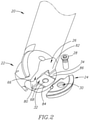
- Each cutting insert 24 is secured to a respective insert pocket 26 by means of a retaining screw 28 passing through an insert through hole 30 in the cutting insert 24 and threadingly received in a pocket hole 32 in a base surface 34 of the insert pocket 26.
- the insert holder 22 may be manufactured from a first material and the cutting insert 24 from a second harder material.
- the milling cutter 20 may have two to four cutting inserts 24 retained in corresponding insert pockets 26.
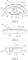
- the cutting insert 24 includes a top surface 36 and an opposing bottom surface 38 with the insert through hole 30 having a central axis C and passing through the top and bottom surfaces 36, 38.
- a peripheral surface 40 extends between the top surface 36 and the bottom surface 38. The peripheral surface 40 encircles the entire cutting insert 24.
- the peripheral surface 40 contains a front arcuate surface 42 and a rear surface 44.
- the rear surface 44 is multifaceted and comprises a central back surface 46, two side abutment surfaces 48, 50 , a first side abutment surface 48 and a second side abutment surface 50 and two rear abutment surfaces 52, 54 , a first rear abutment surface 52 and a second rear abutment surface 54.
- the two side abutment surfaces 48, 50 may be parallel to each other and perpendicular to the central back surface 46.
- the two rear abutment surfaces 52, 54 may be flat and coplanar.
- the central back surface 46 is located between the two side abutment surfaces 48, 50.
- the two side abutment surfaces 48, 50 extend forwardly from the central back surface 46, which is oriented transversely thereto. Each side abutment surface 48, 50 is adjacent to a respective rear abutment surface 52, 54.
- the central back surface 46 and the two side abutment surfaces 48, 50 are located on a protuberance 56 of the cutting insert 24.
- the central back surface 46 is located on a rearwardly facing wall of the protuberance 56 while the two side abutment surfaces 48, 50 are located on laterally outwardly facing walls of protuberance 56.
- the protuberance 56 protrudes beyond the rear abutment surfaces 52, 54 in a direction away from a central region of the front arcuate surface 42.
- a cutting edge 58 is formed where the front arcuate surface 42 meets the top surface 36. Further, an edge 60, which is not a cutting edge, is formed where the front arcuate surface 42 meets the bottom surface 38, that is, the cutting insert 24 is "one-sided".
- the cutting edge 58 may lie on a circular arc where the angle ⁇ subtended at the centre of the circle may be 120°.
- the milling cutter 20 is able to perform milling operations with cutting forces acting in the axial forward direction, and thus operate with an increased range of maneuverability.
- the width of the front arcuate surface 42, between the top and bottom surfaces 36, 38 may be smaller at the sides than in the middle. Furthermore, as seen in Fig. 5 , the front arcuate surface 42 may be inclined inwardly in a direction away from the top surface 36.
- top and bottom surfaces 36, 38 may be substantially planar.
- a stress relief groove 62, 64 on each side of the protuberance 56, running between the protuberance 56 and the rear abutment surfaces 52, 54.
- FIGs. 6, 7 and 8 showing a cutting insert 24.
- a further cutting edge 60 is formed where the front arcuate surface 42 meets the bottom surface 38.
- the cutting edges 58, 60 formed at the top and bottom surfaces 36, 38 are identical so that the insert is double-sided, and can be reversed.
- the cutting insert 24 exhibits 180° rotational symmetry about an axis of symmetry B .
- the axis of symmetry B passes through the central back surface 46, the central axis C of the through hole 30 and also passes through the front arcuate surface 42. It is noted, however, that the cutting insert 24 is non-indexable about its through hole 30, unlike the inserts disclosed in aforementioned U.S. Patent No. 5,951,213 and U.S. Published Application No. 2010/0124465 .
- the axis of symmetry B is perpendicular to and bisects the central back surface 46 .
- each insert pocket 26 has a side wall 66 extending generally upright from the base surface 34 .
- the base surface 34 and the side wall 66 may be perpendicular to each other.
- a socket 68 is formed in the side wall 66 adjacent the base surface 34 .
- the socket 68 has a bottom socket surface 70, an opposing top socket surface 72, a back socket surface 74 and two socket side abutment surfaces 76, 78 , a first socket side abutment surface 76 and a second socket side abutment surface 78.
- the two socket side abutment surfaces 76, 78 may be generally parallel to one another and transverse to the longitudinal axis of rotation (R).
- the back socket surface 74 and socket side abutment surfaces 76, 78 are situated between the top and bottom socket surfaces 72, 70 .
- Each socket side abutment surface 76, 78 extends from the adjacent back socket surface 74 to the side wall 66 .
- the first socket side abutment surface 76 provides primarily axial support for the cutting insert 24 against cutting forces acting in the axial rearward direction.
- Extending along the pocket side wall 66 from adjacent the first and second socket side abutment surfaces 76, 78 and adjacent the insert pocket base surface 34 are first and second side contact surfaces 82, 80, respectively.
- the first and second side contact surfaces 82, 80 are flat and coplanar, not unlike the two rear abutment surfaces 52, 54 formed on the cutting insert 24.
- the first and second side contact surfaces 82, 80 provide primarily radial support for the cutting insert 24.
- the socket 68 may not include the top socket surface 72.
- each insert pocket 26 has two grooves 84, 86 on the base surface 34 running in a direction perpendicular to the side wall 66. These grooves 84, 86 are an outcome of the production method for creating the socket 68.
- the seating and support of the cutting insert 24 in the insert pocket 26 will be described with reference to Figs. 1 , 2 and 10 .
- the protuberance 56 of the cutting insert 24 is located in the socket 68 of the insert holder 22.
- the first abutment region is formed between the bottom surface 38 of the cutting insert 24 and the base surface 34 of the insert holder 22.
- the second abutment region is formed between the first rear abutment surface 52 of the cutting insert 24 and the first side contact surface 82 of the insert holder 22.
- the third abutment region is formed between the second rear abutment surface 54 of the cutting insert 24 and the second side contact surface 80 of the insert holder 22.
- the fourth abutment region arises when the protuberance 56 engages the socket 68 and is formed between the first side abutment surface 48 and the first socket side abutment surface 76.
- the fourth abutment region provides primarily axial support for the cutting insert 24 against cutting forces acting on the cutting insert 24 in the axial rearward direction during a milling operation.
- the second and third abutment regions provide primarily radial support for the cutting insert 24 against cutting forces acting on the cutting insert 24 during a milling operation.
- socket 68 is configured and dimensioned to receive a portion of a cutting insert retained in the associated insert pocket with only one of the two socket side abutment surfaces 76, 78 abutting a side of that portion.
- the second, third and fourth abutment regions are generated by designing the insert through hole 30 to be suitably eccentric in relation to the pocket hole 32. Due to the eccentricity, when the retaining screw 28 is tightened, a biasing force is applied to the cutting insert 24 forcing the cutting insert 24 against the insert pocket 26 at the second, third and fourth abutment regions.
- This arrangement is used for most milling operations in which the axial cutting forces are directed in the forward to rear direction. In such milling operations, there is no contact between the second side abutment surface 50 and the second socket side abutment surface 78.
Landscapes
- Engineering & Computer Science (AREA)
- Mechanical Engineering (AREA)
- Milling Processes (AREA)
- Cutting Tools, Boring Holders, And Turrets (AREA)
- Shovels (AREA)
Claims (8)
- Fräswerkzeug (20), aufweisend:einen Einsatzhalter (22) mit einer Längsdrehachse (R), die eine Vorne-nach-Hinten-Richtung definiert, wobei ein vorderes Ende des Einsatzhalters eine Vielzahl von identischen Einsatztaschen (26) aufweist, wobei jede Einsatztasche (26) aufweist:eine Grundfläche (34);eine Seitenwand (66), aufweisend Seitenkontaktflächen (82, 80);ein Taschenloch (32) in der Grundfläche (34); undeine Aufnahme (68) in der Seitenwand (66), benachbart der Grundfläche (34), wobei die Aufnahme (68) eine untere Aufnahmenfläche (70), eine Aufnahmenrückfläche (74) und zwei seitliche Aufnahmenanlageflächen (76, 78) aufweist, wobei sich jede seitliche Aufnahmenanlagefläche (76, 78) von einer benachbarten Seitenkontaktfläche (82, 80) erstreckt; undeinen Schneideinsatz (24), aufweisend:gegenüberliegende obere und untere Flächen (36, 38) und eine sich dazwischen erstreckende Umfangsfläche (40), wobei die Umfangsfläche (40) eine vordere bogenförmige Fläche (42) undeine hintere Fläche (44) aufweist, wobei die vordere bogenförmige Fläche (42) an zwei Kanten (58, 60) auf die oberen und unteren Flächen (36, 38) trifft, wobei mindestens eine der Kanten (58) eine Schneidkante aufweist;wobei die hintere Fläche (44) eine mittige Rückfläche (46), zwei Seitenanlageflächen (48, 50) und zwei hintere Anlageflächen (52, 54) aufweist, wobei sich die mittige Rückfläche (46) zwischen den beiden Seitenanlageflächen (48, 50) befindet, die sich von dieser nach vorne erstrecken, wobei jede Seitenanlagefläche (48, 50) an eine jeweilige hintere Anlagefläche (52, 54) angrenzt, wobei sich die mittige Rückfläche (46) und die beiden Seitenanlageflächen (48, 50) an einem Vorsprung (56) des Schneideinsatzes (24) befinden, wobei der Vorsprung (56) über die hinteren Anlageflächen (52, 54) in einer Richtung weg von einem mittigen Bereich der vorderen bogenförmigen Fläche (42) hinausragt; undein Einsatzdurchgangsloch (30), das zwischen der oberen und unteren Fläche (36, 38) verläuft, wobei:der Schneideinsatz (24) in jeder Einsatztasche des Einsatzhalters (22) durch eine Halteschraube (28) gehalten wird;sich die Halteschraube (28) in dem Einsatzdurchgangsloch (30) befindet und mittels Gewinde in dem Taschenloch (32) aufgenommen ist;die Grundfläche (34) des Einsatzhalters (22) an der unteren Fläche (38) des Schneideinsatzes (24) anliegt; undsich der Vorsprung (56) in der Aufnahme (68) befindet, wobei die erste Seitenanlagefläche (48) mit der ersten seitlichen Aufnahmenanlagefläche (76) in Anlage steht; dadurch gekennzeichnet, dass die ersten und zweiten Seitenkontaktflächen (82, 80) des Einsatzhalters (22) jeweils an den ersten und zweiten hinteren Anlageflächen (52, 54) des Schneideinsatzes (24) anliegen und dass kein Kontakt zwischen der zweiten Seitenanlagefläche (50) und der zweiten seitlichen Aufnahmenanlagefläche (78) besteht.
- Fräswerkzeug (20) nach Anspruch 1, wobei die beiden Seitenanlageflächen (48, 50) parallel zueinander und senkrecht zu der mittigen Rückfläche (46) sind und vorzugsweise die beiden hinteren Anlageflächen (52, 54) flach und komplanar sind.
- Fräswerkzeug (20) nach Anspruch 1 oder 2, wobei die Grundfläche (34) und die Seitenwand (66) senkrecht zueinander sind.
- Fräswerkzeug (20) nach einem der Ansprüche 1-3, wobei die beiden seitlichen Aufnahmenanlageflächen (76, 78) parallel zueinander und quer zu der Längsdrehachse (R) sind.
- Fräswerkzeug (20) nach einem der Ansprüche 1-4, wobei die Aufnahme (68) ferner eine obere Aufnahmenfläche (72) aufweist, die der unteren Aufnahmenfläche (70) gegenüberliegt.
- Fräswerkzeug (20) nach einem der Ansprüche 1-5, wobei der Schneideinsatz (24) um das Einsatzdurchgangsloch (30) nicht indexierbar ist.
- Fräswerkzeug (20) nach einem der Ansprüche 1-6, wobei:der Schneideinsatz (24) doppelseitig ist;jede der Kanten (58, 60) eine Schneidkante aufweist; undder Schneideinsatz (24) eine 180°-Rotationssymmetrie um eine Symmetrieachse (B) besitzt, die durch die mittige Rückfläche (46), das Durchgangsloch (30) und die vordere bogenförmige Fläche (42) verläuft.
- Fräswerkzeug (20) nach Anspruch 7, wobei:
die Symmetrieachse (B) senkrecht zu der mittigen Rückfläche (46) ist und die mittige Rückfläche (46) halbiert.
Priority Applications (1)
| Application Number | Priority Date | Filing Date | Title |
|---|---|---|---|
| PL20181009T PL3763468T3 (pl) | 2010-09-19 | 2011-07-24 | Frez |
Applications Claiming Priority (3)
| Application Number | Priority Date | Filing Date | Title |
|---|---|---|---|
| IL208253A IL208253A (en) | 2010-09-19 | 2010-09-19 | Milling tools and cutting tool for it |
| PCT/IL2011/000594 WO2012035529A1 (en) | 2010-09-19 | 2011-07-24 | Milling cutter and cutting insert having rear protuberance therefor |
| EP11755151.5A EP2616205B1 (de) | 2010-09-19 | 2011-07-24 | Schneideinsatz mit rückseitiger protuberanz |
Related Parent Applications (2)
| Application Number | Title | Priority Date | Filing Date |
|---|---|---|---|
| EP11755151.5A Division-Into EP2616205B1 (de) | 2010-09-19 | 2011-07-24 | Schneideinsatz mit rückseitiger protuberanz |
| EP11755151.5A Division EP2616205B1 (de) | 2010-09-19 | 2011-07-24 | Schneideinsatz mit rückseitiger protuberanz |
Publications (2)
| Publication Number | Publication Date |
|---|---|
| EP3763468A1 EP3763468A1 (de) | 2021-01-13 |
| EP3763468B1 true EP3763468B1 (de) | 2022-03-16 |
Family
ID=43570207
Family Applications (2)
| Application Number | Title | Priority Date | Filing Date |
|---|---|---|---|
| EP11755151.5A Active EP2616205B1 (de) | 2010-09-19 | 2011-07-24 | Schneideinsatz mit rückseitiger protuberanz |
| EP20181009.0A Active EP3763468B1 (de) | 2010-09-19 | 2011-07-24 | Fräswerkzeug |
Family Applications Before (1)
| Application Number | Title | Priority Date | Filing Date |
|---|---|---|---|
| EP11755151.5A Active EP2616205B1 (de) | 2010-09-19 | 2011-07-24 | Schneideinsatz mit rückseitiger protuberanz |
Country Status (13)
| Country | Link |
|---|---|
| US (1) | US8647027B2 (de) |
| EP (2) | EP2616205B1 (de) |
| JP (1) | JP5857052B2 (de) |
| KR (1) | KR101556832B1 (de) |
| CN (1) | CN103097065B (de) |
| BR (2) | BR122020026357B1 (de) |
| CA (1) | CA2810293C (de) |
| ES (2) | ES2864546T3 (de) |
| IL (1) | IL208253A (de) |
| PL (2) | PL3763468T3 (de) |
| PT (1) | PT2616205T (de) |
| RU (1) | RU2560466C2 (de) |
| WO (1) | WO2012035529A1 (de) |
Families Citing this family (11)
| Publication number | Priority date | Publication date | Assignee | Title |
|---|---|---|---|---|
| US9511426B2 (en) | 2012-06-21 | 2016-12-06 | Tungaloy Corporation | Cutting insert, tool body on which said cutting insert may be mounted, and replaceable-blade-type ball-end mill provided therewith |
| US9162296B2 (en) | 2012-08-21 | 2015-10-20 | Iscar, Ltd. | Chamfering cutter and chamfering insert therefor |
| WO2014181811A1 (ja) * | 2013-05-10 | 2014-11-13 | 株式会社タンガロイ | 切削インサート、該切削インサートを装着可能な工具ボデー並びにこれらを備えた刃先交換式切削工具及びボールエンドミル |
| US9475131B2 (en) * | 2013-06-13 | 2016-10-25 | Kennametal Inc. | Milling cutter with stress reliefs |
| RU2018130486A (ru) | 2013-07-31 | 2019-03-20 | Дайдо Диэ энд Моулд Стил Солюшенз Ко., Лтд. | Способ изготовления колена, режущий инструмент и колено |
| US9700947B2 (en) | 2014-06-27 | 2017-07-11 | Kennametal Inc. | Ballnose cutting tool and ballnose cutting insert |
| DE102015102044B4 (de) * | 2015-02-12 | 2024-12-24 | Kennametal Inc. | Fräswerkzeug und Schneideinsatz |
| JP6562983B2 (ja) * | 2017-08-10 | 2019-08-21 | 株式会社タンガロイ | 切削インサート及び切削工具 |
| DE102019123968A1 (de) * | 2019-09-06 | 2021-03-11 | Gühring KG | Kugelbahnfräser mit einem Trägerkörper und ein Verfahren zum Wiederherstellen eines Kugelbahnfräsers |
| JP7012949B1 (ja) * | 2021-07-15 | 2022-01-31 | 株式会社タンガロイ | 切削インサートおよび刃先交換式回転切削工具とそのボデー |
| US11433460B1 (en) * | 2021-10-26 | 2022-09-06 | Prince Mohammad Bin Fahd University | Cutting insert |
Family Cites Families (64)
| Publication number | Priority date | Publication date | Assignee | Title |
|---|---|---|---|---|
| SU97109A1 (ru) * | 1952-11-25 | 1953-11-30 | Г.М. Богельман | Концева фреза дл обработки пространственно-сложных поверхностей штампов, прессформ, кулачков и тому подобных изделий |
| US3158922A (en) * | 1962-04-16 | 1964-12-01 | Ray H Reese | Indexable blade pocket mill |
| US3466720A (en) | 1967-11-08 | 1969-09-16 | Carmet Co | Reversible throw-away cutting inserts |
| US3621549A (en) * | 1970-03-06 | 1971-11-23 | James O Billups | Cutting tool insert assembly |
| SU835667A1 (ru) * | 1977-03-28 | 1981-06-07 | Всесоюзный Научно-Исследовательскийинструментальный Институт | Концева фреза |
| SE452271B (sv) * | 1982-04-01 | 1987-11-23 | Sandvik Ab | Sker och verktyg for spanskerande bearbetning |
| SE450351B (sv) * | 1983-01-18 | 1987-06-22 | Sandvik Ab | Skerverktyg och sker for spanavskiljande bearbetning |
| US4536037A (en) * | 1983-07-18 | 1985-08-20 | Huron Manufacturing Corporation | Cutting tooth for strip mining apparatus |
| US4593734A (en) * | 1983-09-26 | 1986-06-10 | M. Bosley Wright | Frame routing apparatus |
| DE3618574C2 (de) * | 1985-06-06 | 1989-11-02 | Mitsubishi Kinzoku K.K., Tokio/Tokyo, Jp | Positiv-wendeschneidplatte |
| SU1683901A1 (ru) * | 1988-04-29 | 1991-10-15 | Предприятие П/Я Г-4149 | Концева фреза |
| JPH088015Y2 (ja) * | 1990-03-30 | 1996-03-06 | 三菱マテリアル株式会社 | 転削工具におけるチップのクランプ機構 |
| US5222841A (en) * | 1991-02-15 | 1993-06-29 | Graco Inc. | Form tool system |
| DE4312401A1 (de) * | 1993-04-16 | 1994-10-20 | Widia Heinlein Gmbh | Schneidplatte |
| IL105758A (en) * | 1993-05-20 | 1996-01-31 | Iscar Ltd | Indexable-insert drill |
| IL106999A (en) * | 1993-09-13 | 1997-02-18 | Iscar Ltd | Cutting tool |
| IL108115A (en) * | 1993-12-21 | 1997-02-18 | Iscar Ltd | Chip cutting tool |
| AUPN268395A0 (en) * | 1995-04-27 | 1995-05-25 | Ziegler, Karl | Improvements in machine tools |
| US5782589A (en) * | 1996-06-17 | 1998-07-21 | Cole; John M. | Milling cutter |
| US6158927A (en) * | 1996-06-17 | 2000-12-12 | Cole Carbide Industries, Inc. | Milling cutter |
| DE19624342C1 (de) | 1996-06-19 | 1997-12-11 | Walter Ag | Schneidplatte und Fräser, insbesondere Kugelstirnfräser oder Kopierfräser |
| IL119113A (en) * | 1996-08-22 | 2000-10-31 | Iscar Ltd | Cutting insert |
| AUPO304396A0 (en) * | 1996-10-17 | 1996-11-14 | Ziegler, Karl | Cutting assembly |
| IT1288262B1 (it) * | 1996-12-13 | 1998-09-11 | Livio Mina | Fresa bitagliente monoinserto ad elevata robustezza e precisione |
| US5893683A (en) * | 1997-04-29 | 1999-04-13 | Ingersoll Cutting Tool Company | Indexable insert router |
| TW431922B (en) * | 1998-04-29 | 2001-05-01 | Iscar Ltd | A cutting insert and a cutting tool assembly |
| US6071045A (en) * | 1998-05-06 | 2000-06-06 | Janness; Daniel | Cutting insert and tool |
| IL125143A (en) | 1998-06-30 | 2007-02-11 | Amir Satran | Cutting insert |
| IL125298A (en) * | 1998-07-10 | 2001-10-31 | Iscar Ltd | Rotary cutting tool |
| JP3330085B2 (ja) * | 1998-08-31 | 2002-09-30 | 京セラ株式会社 | 内径加工用工具 |
| JP3279292B2 (ja) * | 1999-08-02 | 2002-04-30 | 住友電気工業株式会社 | 刃先交換式回転切削工具 |
| IL132261A (en) * | 1999-10-07 | 2003-09-17 | Iscar Ltd | Cutting tool assembly and cutting insert therefor |
| IL134226A (en) * | 2000-01-26 | 2003-12-10 | Iscar Ltd | Cutting tool assembly |
| IL139957A0 (en) * | 2000-11-28 | 2002-02-10 | Iscar Ltd | Cutting tool |
| DE10017645A1 (de) * | 2000-04-08 | 2001-10-11 | Sandvik Ab | Schneideinsatz für Nockenwellenfräser |
| SE520629C2 (sv) * | 2000-09-05 | 2003-08-05 | Sandvik Ab | Skär för grovsvarvningsändamål med avsmalnande bakre ände |
| US6527485B1 (en) * | 2000-11-22 | 2003-03-04 | Tooling Specialties, Inc. | Threading apparatus |
| IL150783A0 (en) * | 2001-10-16 | 2003-02-12 | Iscar Ltd | Cutting tool and cutting insert therefor |
| JP2003159611A (ja) * | 2001-11-22 | 2003-06-03 | Kyocera Corp | ボールエンドミルおよびその製造方法 |
| AT6618U1 (de) * | 2002-08-16 | 2004-01-26 | Plansee Tizit Ag | Schneidwerkzeug zum drehen und bohren ins volle |
| US7001115B2 (en) * | 2003-07-21 | 2006-02-21 | Kennametal Inc. | Cutting insert and toolholder for holding the same |
| US7044695B2 (en) * | 2004-07-02 | 2006-05-16 | Stojan Stojanovski | Milling tool |
| SE529067C2 (sv) * | 2004-08-25 | 2007-04-24 | Seco Tools Ab | Vändskär med skärhålsarrangemang med två axlar |
| US7226249B2 (en) * | 2004-10-29 | 2007-06-05 | Mitsubishi Materials Corporation | Ball nose cutting insert and ball end mill thereof |
| IL165621A (en) * | 2004-12-07 | 2008-06-05 | Iscar Ltd | Cutting tool and cutting insert therefor |
| SE528710C2 (sv) * | 2005-06-01 | 2007-01-30 | Sandvik Intellectual Property | Indexerbart frässkär med kopplingsmedlet anordnat på en släppningsyta |
| IL174670A (en) * | 2006-03-30 | 2011-12-29 | Gil Hecht | Cutting Tools |
| JP2007268695A (ja) * | 2006-03-31 | 2007-10-18 | Kyocera Corp | 切削工具およびホルダ |
| SE530236C2 (sv) * | 2006-07-04 | 2008-04-08 | Seco Tools Ab | Frässkär och fräsverktyg där en utskjutande del av skäret bildar ett mönster i arbetsstycket |
| DE102006035182A1 (de) * | 2006-07-29 | 2008-01-31 | Hartmetall-Werkzeugfabrik Paul Horn Gmbh | Werkzeugsystem |
| US7677282B2 (en) * | 2006-11-22 | 2010-03-16 | Key Knife, Inc. | Knife assembly and chipping knife therefor |
| IL185048A (en) * | 2007-08-05 | 2011-07-31 | Iscar Ltd | Cutting tool and cutting tool for it |
| IL185047A (en) * | 2007-08-05 | 2011-09-27 | Iscar Ltd | Cutting Tools |
| US20090052999A1 (en) * | 2007-08-24 | 2009-02-26 | Aggressive Equipment, Inc. | Cutting insert and method |
| IL191415A (en) * | 2008-05-13 | 2013-01-31 | Iscar Ltd | Cutting tool and cutting tool for it |
| IL194030A (en) * | 2008-09-11 | 2012-03-29 | Iscar Ltd | Cutting tool and cutting tool for it |
| US9623493B2 (en) | 2008-11-19 | 2017-04-18 | Kennametal Inc. | Double-sided ball end mill cutting insert and tool therefor |
| US8177459B2 (en) * | 2008-11-26 | 2012-05-15 | Greenleaf Technology Corporation | Ball nose end mill and insert |
| US8192114B2 (en) * | 2009-02-09 | 2012-06-05 | Hsin-Tien Chang | Combination of center drill and drill holding tool |
| WO2010092574A1 (en) | 2009-02-11 | 2010-08-19 | Simatate Ltd. | Multi-edge cutting head and an insert used therein |
| WO2010100953A1 (ja) * | 2009-03-06 | 2010-09-10 | 三菱マテリアル株式会社 | 切削インサートおよびインサート着脱式切削工具 |
| IL198053A (en) * | 2009-04-07 | 2012-03-29 | Iscar Ltd | Cutting and applying tools for him |
| IL202026A (en) * | 2009-11-10 | 2013-06-27 | Iscar Ltd | Cutting tools and a tool for him |
| EP2420340B1 (de) * | 2010-08-20 | 2014-04-16 | VARGUS Ltd. | Gewindefrässchneideinsatz und Gewindefräser |
-
2010
- 2010-09-19 IL IL208253A patent/IL208253A/en active IP Right Grant
-
2011
- 2011-07-24 CN CN201180044795.0A patent/CN103097065B/zh active Active
- 2011-07-24 WO PCT/IL2011/000594 patent/WO2012035529A1/en not_active Ceased
- 2011-07-24 EP EP11755151.5A patent/EP2616205B1/de active Active
- 2011-07-24 RU RU2013118000/02A patent/RU2560466C2/ru active
- 2011-07-24 JP JP2013528830A patent/JP5857052B2/ja active Active
- 2011-07-24 EP EP20181009.0A patent/EP3763468B1/de active Active
- 2011-07-24 BR BR122020026357-1A patent/BR122020026357B1/pt active IP Right Grant
- 2011-07-24 PL PL20181009T patent/PL3763468T3/pl unknown
- 2011-07-24 CA CA2810293A patent/CA2810293C/en active Active
- 2011-07-24 ES ES11755151T patent/ES2864546T3/es active Active
- 2011-07-24 PT PT117551515T patent/PT2616205T/pt unknown
- 2011-07-24 ES ES20181009T patent/ES2916699T3/es active Active
- 2011-07-24 KR KR1020137006818A patent/KR101556832B1/ko active Active
- 2011-07-24 BR BR112013003966-3A patent/BR112013003966B1/pt active IP Right Grant
- 2011-07-24 PL PL11755151T patent/PL2616205T3/pl unknown
- 2011-09-01 US US13/223,960 patent/US8647027B2/en active Active
Also Published As
| Publication number | Publication date |
|---|---|
| ES2864546T3 (es) | 2021-10-14 |
| RU2560466C2 (ru) | 2015-08-20 |
| RU2013118000A (ru) | 2014-10-27 |
| BR112013003966A2 (pt) | 2020-07-21 |
| JP5857052B2 (ja) | 2016-02-10 |
| EP2616205A1 (de) | 2013-07-24 |
| IL208253A0 (en) | 2010-12-30 |
| US20120070238A1 (en) | 2012-03-22 |
| CA2810293C (en) | 2016-09-13 |
| US8647027B2 (en) | 2014-02-11 |
| CN103097065A (zh) | 2013-05-08 |
| EP2616205B1 (de) | 2021-04-07 |
| CN103097065B (zh) | 2016-03-30 |
| BR122020026357B1 (pt) | 2023-05-16 |
| EP3763468A1 (de) | 2021-01-13 |
| BR112013003966B1 (pt) | 2021-03-30 |
| ES2916699T3 (es) | 2022-07-05 |
| KR20130105835A (ko) | 2013-09-26 |
| KR101556832B1 (ko) | 2015-10-13 |
| WO2012035529A1 (en) | 2012-03-22 |
| JP2013537117A (ja) | 2013-09-30 |
| PL2616205T3 (pl) | 2021-10-18 |
| CA2810293A1 (en) | 2012-03-22 |
| PL3763468T3 (pl) | 2022-05-16 |
| IL208253A (en) | 2015-01-29 |
| PT2616205T (pt) | 2021-06-22 |
Similar Documents
| Publication | Publication Date | Title |
|---|---|---|
| EP2616205B1 (de) | Schneideinsatz mit rückseitiger protuberanz | |
| EP2101947B1 (de) | Schneideinsatz und schneidwerkzeug | |
| KR101292441B1 (ko) | 접선식 절삭 삽입체 | |
| US9623493B2 (en) | Double-sided ball end mill cutting insert and tool therefor | |
| CN110497006B (zh) | 切削刀片以及切削工具 | |
| JP5919832B2 (ja) | 切削インサートおよび刃先交換式切削工具 | |
| JP2013103332A (ja) | ランピング能力を有するインデックス可能な両面切削インサート及びそのための切削工具 | |
| JP5735502B2 (ja) | 切削加工、特に高速送りフライス加工するための切削工具用切削インサート | |
| PL177807B1 (pl) | Wkładka skrawająca | |
| CN103128350A (zh) | 切削刀片和铣削刀具 | |
| CN104540623B (zh) | 车床车削工具 | |
| CN102046313A (zh) | 切削刀片套组、铣削刀具和切削刀片 | |
| JPWO2008123424A1 (ja) | シート部材およびそれを用いた回転工具並びにそれを用いた切削方法 | |
| JP4456852B2 (ja) | スローアウェイ式ドリル | |
| EP3582919B1 (de) | Werkzeugkörper mit inneneinsatzaufnahmetasche mit elastischem klemmelement, schneidwerkzeug und abfasschneideinsatz dafür | |
| CN113840677A (zh) | 高进给车削工具组件 | |
| CA3211642A1 (en) | Cutting insert and cutting tool | |
| EP4717385A1 (de) | Fräswerkzeugkörper und fräswerkzeug | |
| EP4691675A1 (de) | Schneideinsatz und rotierendes schneidwerkzeug mit indizierbarer schneidkante |
Legal Events
| Date | Code | Title | Description |
|---|---|---|---|
| PUAI | Public reference made under article 153(3) epc to a published international application that has entered the european phase |
Free format text: ORIGINAL CODE: 0009012 |
|
| STAA | Information on the status of an ep patent application or granted ep patent |
Free format text: STATUS: THE APPLICATION HAS BEEN PUBLISHED |
|
| AC | Divisional application: reference to earlier application |
Ref document number: 2616205 Country of ref document: EP Kind code of ref document: P |
|
| AK | Designated contracting states |
Kind code of ref document: A1 Designated state(s): AL AT BE BG CH CY CZ DE DK EE ES FI FR GB GR HR HU IE IS IT LI LT LU LV MC MK MT NL NO PL PT RO RS SE SI SK SM TR |
|
| STAA | Information on the status of an ep patent application or granted ep patent |
Free format text: STATUS: REQUEST FOR EXAMINATION WAS MADE |
|
| 17P | Request for examination filed |
Effective date: 20210423 |
|
| RBV | Designated contracting states (corrected) |
Designated state(s): AL AT BE BG CH CY CZ DE DK EE ES FI FR GB GR HR HU IE IS IT LI LT LU LV MC MK MT NL NO PL PT RO RS SE SI SK SM TR |
|
| RIC1 | Information provided on ipc code assigned before grant |
Ipc: B23C 5/22 20060101ALI20210819BHEP Ipc: B23C 5/10 20060101AFI20210819BHEP |
|
| GRAP | Despatch of communication of intention to grant a patent |
Free format text: ORIGINAL CODE: EPIDOSNIGR1 |
|
| STAA | Information on the status of an ep patent application or granted ep patent |
Free format text: STATUS: GRANT OF PATENT IS INTENDED |
|
| INTG | Intention to grant announced |
Effective date: 20210929 |
|
| GRAS | Grant fee paid |
Free format text: ORIGINAL CODE: EPIDOSNIGR3 |
|
| GRAA | (expected) grant |
Free format text: ORIGINAL CODE: 0009210 |
|
| STAA | Information on the status of an ep patent application or granted ep patent |
Free format text: STATUS: THE PATENT HAS BEEN GRANTED |
|
| AC | Divisional application: reference to earlier application |
Ref document number: 2616205 Country of ref document: EP Kind code of ref document: P |
|
| AK | Designated contracting states |
Kind code of ref document: B1 Designated state(s): AL AT BE BG CH CY CZ DE DK EE ES FI FR GB GR HR HU IE IS IT LI LT LU LV MC MK MT NL NO PL PT RO RS SE SI SK SM TR |
|
| REG | Reference to a national code |
Ref country code: GB Ref legal event code: FG4D |
|
| REG | Reference to a national code |
Ref country code: CH Ref legal event code: EP |
|
| REG | Reference to a national code |
Ref country code: DE Ref legal event code: R096 Ref document number: 602011072641 Country of ref document: DE |
|
| REG | Reference to a national code |
Ref country code: IE Ref legal event code: FG4D |
|
| REG | Reference to a national code |
Ref country code: AT Ref legal event code: REF Ref document number: 1475532 Country of ref document: AT Kind code of ref document: T Effective date: 20220415 |
|
| REG | Reference to a national code |
Ref country code: SE Ref legal event code: TRGR |
|
| REG | Reference to a national code |
Ref country code: ES Ref legal event code: FG2A Ref document number: 2916699 Country of ref document: ES Kind code of ref document: T3 Effective date: 20220705 |
|
| REG | Reference to a national code |
Ref country code: LT Ref legal event code: MG9D |
|
| REG | Reference to a national code |
Ref country code: NL Ref legal event code: MP Effective date: 20220316 |
|
| PG25 | Lapsed in a contracting state [announced via postgrant information from national office to epo] |
Ref country code: RS Free format text: LAPSE BECAUSE OF FAILURE TO SUBMIT A TRANSLATION OF THE DESCRIPTION OR TO PAY THE FEE WITHIN THE PRESCRIBED TIME-LIMIT Effective date: 20220316 Ref country code: NO Free format text: LAPSE BECAUSE OF FAILURE TO SUBMIT A TRANSLATION OF THE DESCRIPTION OR TO PAY THE FEE WITHIN THE PRESCRIBED TIME-LIMIT Effective date: 20220616 Ref country code: LT Free format text: LAPSE BECAUSE OF FAILURE TO SUBMIT A TRANSLATION OF THE DESCRIPTION OR TO PAY THE FEE WITHIN THE PRESCRIBED TIME-LIMIT Effective date: 20220316 Ref country code: HR Free format text: LAPSE BECAUSE OF FAILURE TO SUBMIT A TRANSLATION OF THE DESCRIPTION OR TO PAY THE FEE WITHIN THE PRESCRIBED TIME-LIMIT Effective date: 20220316 Ref country code: BG Free format text: LAPSE BECAUSE OF FAILURE TO SUBMIT A TRANSLATION OF THE DESCRIPTION OR TO PAY THE FEE WITHIN THE PRESCRIBED TIME-LIMIT Effective date: 20220616 |
|
| PG25 | Lapsed in a contracting state [announced via postgrant information from national office to epo] |
Ref country code: LV Free format text: LAPSE BECAUSE OF FAILURE TO SUBMIT A TRANSLATION OF THE DESCRIPTION OR TO PAY THE FEE WITHIN THE PRESCRIBED TIME-LIMIT Effective date: 20220316 Ref country code: GR Free format text: LAPSE BECAUSE OF FAILURE TO SUBMIT A TRANSLATION OF THE DESCRIPTION OR TO PAY THE FEE WITHIN THE PRESCRIBED TIME-LIMIT Effective date: 20220617 Ref country code: FI Free format text: LAPSE BECAUSE OF FAILURE TO SUBMIT A TRANSLATION OF THE DESCRIPTION OR TO PAY THE FEE WITHIN THE PRESCRIBED TIME-LIMIT Effective date: 20220316 |
|
| PG25 | Lapsed in a contracting state [announced via postgrant information from national office to epo] |
Ref country code: NL Free format text: LAPSE BECAUSE OF FAILURE TO SUBMIT A TRANSLATION OF THE DESCRIPTION OR TO PAY THE FEE WITHIN THE PRESCRIBED TIME-LIMIT Effective date: 20220316 |
|
| PG25 | Lapsed in a contracting state [announced via postgrant information from national office to epo] |
Ref country code: SM Free format text: LAPSE BECAUSE OF FAILURE TO SUBMIT A TRANSLATION OF THE DESCRIPTION OR TO PAY THE FEE WITHIN THE PRESCRIBED TIME-LIMIT Effective date: 20220316 Ref country code: SK Free format text: LAPSE BECAUSE OF FAILURE TO SUBMIT A TRANSLATION OF THE DESCRIPTION OR TO PAY THE FEE WITHIN THE PRESCRIBED TIME-LIMIT Effective date: 20220316 Ref country code: RO Free format text: LAPSE BECAUSE OF FAILURE TO SUBMIT A TRANSLATION OF THE DESCRIPTION OR TO PAY THE FEE WITHIN THE PRESCRIBED TIME-LIMIT Effective date: 20220316 Ref country code: EE Free format text: LAPSE BECAUSE OF FAILURE TO SUBMIT A TRANSLATION OF THE DESCRIPTION OR TO PAY THE FEE WITHIN THE PRESCRIBED TIME-LIMIT Effective date: 20220316 |
|
| PG25 | Lapsed in a contracting state [announced via postgrant information from national office to epo] |
Ref country code: IS Free format text: LAPSE BECAUSE OF FAILURE TO SUBMIT A TRANSLATION OF THE DESCRIPTION OR TO PAY THE FEE WITHIN THE PRESCRIBED TIME-LIMIT Effective date: 20220716 Ref country code: AL Free format text: LAPSE BECAUSE OF FAILURE TO SUBMIT A TRANSLATION OF THE DESCRIPTION OR TO PAY THE FEE WITHIN THE PRESCRIBED TIME-LIMIT Effective date: 20220316 |
|
| REG | Reference to a national code |
Ref country code: DE Ref legal event code: R097 Ref document number: 602011072641 Country of ref document: DE |
|
| PLBE | No opposition filed within time limit |
Free format text: ORIGINAL CODE: 0009261 |
|
| STAA | Information on the status of an ep patent application or granted ep patent |
Free format text: STATUS: NO OPPOSITION FILED WITHIN TIME LIMIT |
|
| PG25 | Lapsed in a contracting state [announced via postgrant information from national office to epo] |
Ref country code: DK Free format text: LAPSE BECAUSE OF FAILURE TO SUBMIT A TRANSLATION OF THE DESCRIPTION OR TO PAY THE FEE WITHIN THE PRESCRIBED TIME-LIMIT Effective date: 20220316 |
|
| 26N | No opposition filed |
Effective date: 20221219 |
|
| PG25 | Lapsed in a contracting state [announced via postgrant information from national office to epo] |
Ref country code: SI Free format text: LAPSE BECAUSE OF FAILURE TO SUBMIT A TRANSLATION OF THE DESCRIPTION OR TO PAY THE FEE WITHIN THE PRESCRIBED TIME-LIMIT Effective date: 20220316 Ref country code: MC Free format text: LAPSE BECAUSE OF FAILURE TO SUBMIT A TRANSLATION OF THE DESCRIPTION OR TO PAY THE FEE WITHIN THE PRESCRIBED TIME-LIMIT Effective date: 20220316 |
|
| REG | Reference to a national code |
Ref country code: CH Ref legal event code: PL |
|
| REG | Reference to a national code |
Ref country code: BE Ref legal event code: MM Effective date: 20220731 |
|
| PG25 | Lapsed in a contracting state [announced via postgrant information from national office to epo] |
Ref country code: LU Free format text: LAPSE BECAUSE OF NON-PAYMENT OF DUE FEES Effective date: 20220724 Ref country code: LI Free format text: LAPSE BECAUSE OF NON-PAYMENT OF DUE FEES Effective date: 20220731 Ref country code: CH Free format text: LAPSE BECAUSE OF NON-PAYMENT OF DUE FEES Effective date: 20220731 |
|
| REG | Reference to a national code |
Ref country code: AT Ref legal event code: UEP Ref document number: 1475532 Country of ref document: AT Kind code of ref document: T Effective date: 20220316 |
|
| PG25 | Lapsed in a contracting state [announced via postgrant information from national office to epo] |
Ref country code: BE Free format text: LAPSE BECAUSE OF NON-PAYMENT OF DUE FEES Effective date: 20220731 |
|
| PG25 | Lapsed in a contracting state [announced via postgrant information from national office to epo] |
Ref country code: IE Free format text: LAPSE BECAUSE OF NON-PAYMENT OF DUE FEES Effective date: 20220724 |
|
| PG25 | Lapsed in a contracting state [announced via postgrant information from national office to epo] |
Ref country code: MK Free format text: LAPSE BECAUSE OF FAILURE TO SUBMIT A TRANSLATION OF THE DESCRIPTION OR TO PAY THE FEE WITHIN THE PRESCRIBED TIME-LIMIT Effective date: 20220316 Ref country code: CY Free format text: LAPSE BECAUSE OF FAILURE TO SUBMIT A TRANSLATION OF THE DESCRIPTION OR TO PAY THE FEE WITHIN THE PRESCRIBED TIME-LIMIT Effective date: 20220316 |
|
| PG25 | Lapsed in a contracting state [announced via postgrant information from national office to epo] |
Ref country code: HU Free format text: LAPSE BECAUSE OF FAILURE TO SUBMIT A TRANSLATION OF THE DESCRIPTION OR TO PAY THE FEE WITHIN THE PRESCRIBED TIME-LIMIT; INVALID AB INITIO Effective date: 20110724 |
|
| PG25 | Lapsed in a contracting state [announced via postgrant information from national office to epo] |
Ref country code: MT Free format text: LAPSE BECAUSE OF FAILURE TO SUBMIT A TRANSLATION OF THE DESCRIPTION OR TO PAY THE FEE WITHIN THE PRESCRIBED TIME-LIMIT Effective date: 20220316 |
|
| PGFP | Annual fee paid to national office [announced via postgrant information from national office to epo] |
Ref country code: PL Payment date: 20250603 Year of fee payment: 15 |
|
| PGFP | Annual fee paid to national office [announced via postgrant information from national office to epo] |
Ref country code: GB Payment date: 20250604 Year of fee payment: 15 |
|
| PGFP | Annual fee paid to national office [announced via postgrant information from national office to epo] |
Ref country code: PT Payment date: 20250613 Year of fee payment: 15 |
|
| PGFP | Annual fee paid to national office [announced via postgrant information from national office to epo] |
Ref country code: FR Payment date: 20250603 Year of fee payment: 15 |
|
| PGFP | Annual fee paid to national office [announced via postgrant information from national office to epo] |
Ref country code: TR Payment date: 20250625 Year of fee payment: 15 |
|
| PGFP | Annual fee paid to national office [announced via postgrant information from national office to epo] |
Ref country code: CZ Payment date: 20250603 Year of fee payment: 15 |
|
| PGFP | Annual fee paid to national office [announced via postgrant information from national office to epo] |
Ref country code: SE Payment date: 20250602 Year of fee payment: 15 |
|
| PGFP | Annual fee paid to national office [announced via postgrant information from national office to epo] |
Ref country code: ES Payment date: 20250821 Year of fee payment: 15 |
|
| PGFP | Annual fee paid to national office [announced via postgrant information from national office to epo] |
Ref country code: DE Payment date: 20250603 Year of fee payment: 15 |
|
| PGFP | Annual fee paid to national office [announced via postgrant information from national office to epo] |
Ref country code: IT Payment date: 20250617 Year of fee payment: 15 |
|
| PGFP | Annual fee paid to national office [announced via postgrant information from national office to epo] |
Ref country code: AT Payment date: 20250603 Year of fee payment: 15 |