EP3763555A2 - Configurations d'entraînement pour véhicules à direction à glissement - Google Patents
Configurations d'entraînement pour véhicules à direction à glissement Download PDFInfo
- Publication number
- EP3763555A2 EP3763555A2 EP20193200.1A EP20193200A EP3763555A2 EP 3763555 A2 EP3763555 A2 EP 3763555A2 EP 20193200 A EP20193200 A EP 20193200A EP 3763555 A2 EP3763555 A2 EP 3763555A2
- Authority
- EP
- European Patent Office
- Prior art keywords
- torque
- drive configuration
- differential
- vehicle
- connection
- Prior art date
- Legal status (The legal status is an assumption and is not a legal conclusion. Google has not performed a legal analysis and makes no representation as to the accuracy of the status listed.)
- Granted
Links
Images



Classifications
-
- B—PERFORMING OPERATIONS; TRANSPORTING
- B62—LAND VEHICLES FOR TRAVELLING OTHERWISE THAN ON RAILS
- B62D—MOTOR VEHICLES; TRAILERS
- B62D11/00—Steering non-deflectable wheels; Steering endless tracks or the like
- B62D11/02—Steering non-deflectable wheels; Steering endless tracks or the like by differentially driving ground-engaging elements on opposite vehicle sides
- B62D11/06—Steering non-deflectable wheels; Steering endless tracks or the like by differentially driving ground-engaging elements on opposite vehicle sides by means of a single main power source
- B62D11/10—Steering non-deflectable wheels; Steering endless tracks or the like by differentially driving ground-engaging elements on opposite vehicle sides by means of a single main power source using gearings with differential power outputs on opposite sides, e.g. twin-differential or epicyclic gears
- B62D11/14—Steering non-deflectable wheels; Steering endless tracks or the like by differentially driving ground-engaging elements on opposite vehicle sides by means of a single main power source using gearings with differential power outputs on opposite sides, e.g. twin-differential or epicyclic gears differential power outputs being effected by additional power supply to one side, e.g. power originating from secondary power source
-
- B—PERFORMING OPERATIONS; TRANSPORTING
- B60—VEHICLES IN GENERAL
- B60K—ARRANGEMENT OR MOUNTING OF PROPULSION UNITS OR OF TRANSMISSIONS IN VEHICLES; ARRANGEMENT OR MOUNTING OF PLURAL DIVERSE PRIME-MOVERS IN VEHICLES; AUXILIARY DRIVES FOR VEHICLES; INSTRUMENTATION OR DASHBOARDS FOR VEHICLES; ARRANGEMENTS IN CONNECTION WITH COOLING, AIR INTAKE, GAS EXHAUST OR FUEL SUPPLY OF PROPULSION UNITS IN VEHICLES
- B60K17/00—Arrangement or mounting of transmissions in vehicles
- B60K17/04—Arrangement or mounting of transmissions in vehicles characterised by arrangement, location or kind of gearing
- B60K17/16—Arrangement or mounting of transmissions in vehicles characterised by arrangement, location or kind of gearing of differential gearing
-
- B—PERFORMING OPERATIONS; TRANSPORTING
- B60—VEHICLES IN GENERAL
- B60K—ARRANGEMENT OR MOUNTING OF PROPULSION UNITS OR OF TRANSMISSIONS IN VEHICLES; ARRANGEMENT OR MOUNTING OF PLURAL DIVERSE PRIME-MOVERS IN VEHICLES; AUXILIARY DRIVES FOR VEHICLES; INSTRUMENTATION OR DASHBOARDS FOR VEHICLES; ARRANGEMENTS IN CONNECTION WITH COOLING, AIR INTAKE, GAS EXHAUST OR FUEL SUPPLY OF PROPULSION UNITS IN VEHICLES
- B60K23/00—Arrangement or mounting of control devices for vehicle transmissions, or parts thereof, not otherwise provided for
- B60K23/04—Arrangement or mounting of control devices for vehicle transmissions, or parts thereof, not otherwise provided for for differential gearing
-
- B—PERFORMING OPERATIONS; TRANSPORTING
- B60—VEHICLES IN GENERAL
- B60K—ARRANGEMENT OR MOUNTING OF PROPULSION UNITS OR OF TRANSMISSIONS IN VEHICLES; ARRANGEMENT OR MOUNTING OF PLURAL DIVERSE PRIME-MOVERS IN VEHICLES; AUXILIARY DRIVES FOR VEHICLES; INSTRUMENTATION OR DASHBOARDS FOR VEHICLES; ARRANGEMENTS IN CONNECTION WITH COOLING, AIR INTAKE, GAS EXHAUST OR FUEL SUPPLY OF PROPULSION UNITS IN VEHICLES
- B60K6/00—Arrangement or mounting of plural diverse prime-movers for mutual or common propulsion, e.g. hybrid propulsion systems comprising electric motors and internal combustion engines
- B60K6/20—Arrangement or mounting of plural diverse prime-movers for mutual or common propulsion, e.g. hybrid propulsion systems comprising electric motors and internal combustion engines the prime-movers consisting of electric motors and internal combustion engines, e.g. HEVs
- B60K6/42—Arrangement or mounting of plural diverse prime-movers for mutual or common propulsion, e.g. hybrid propulsion systems comprising electric motors and internal combustion engines the prime-movers consisting of electric motors and internal combustion engines, e.g. HEVs characterised by the architecture of the hybrid electric vehicle
- B60K6/48—Parallel type
-
- B—PERFORMING OPERATIONS; TRANSPORTING
- B60—VEHICLES IN GENERAL
- B60K—ARRANGEMENT OR MOUNTING OF PROPULSION UNITS OR OF TRANSMISSIONS IN VEHICLES; ARRANGEMENT OR MOUNTING OF PLURAL DIVERSE PRIME-MOVERS IN VEHICLES; AUXILIARY DRIVES FOR VEHICLES; INSTRUMENTATION OR DASHBOARDS FOR VEHICLES; ARRANGEMENTS IN CONNECTION WITH COOLING, AIR INTAKE, GAS EXHAUST OR FUEL SUPPLY OF PROPULSION UNITS IN VEHICLES
- B60K6/00—Arrangement or mounting of plural diverse prime-movers for mutual or common propulsion, e.g. hybrid propulsion systems comprising electric motors and internal combustion engines
- B60K6/20—Arrangement or mounting of plural diverse prime-movers for mutual or common propulsion, e.g. hybrid propulsion systems comprising electric motors and internal combustion engines the prime-movers consisting of electric motors and internal combustion engines, e.g. HEVs
- B60K6/42—Arrangement or mounting of plural diverse prime-movers for mutual or common propulsion, e.g. hybrid propulsion systems comprising electric motors and internal combustion engines the prime-movers consisting of electric motors and internal combustion engines, e.g. HEVs characterised by the architecture of the hybrid electric vehicle
- B60K6/48—Parallel type
- B60K6/485—Motor-assist type
-
- B—PERFORMING OPERATIONS; TRANSPORTING
- B60—VEHICLES IN GENERAL
- B60W—CONJOINT CONTROL OF VEHICLE SUB-UNITS OF DIFFERENT TYPE OR DIFFERENT FUNCTION; CONTROL SYSTEMS SPECIALLY ADAPTED FOR HYBRID VEHICLES; ROAD VEHICLE DRIVE CONTROL SYSTEMS FOR PURPOSES NOT RELATED TO THE CONTROL OF A PARTICULAR SUB-UNIT
- B60W10/00—Conjoint control of vehicle sub-units of different type or different function
- B60W10/04—Conjoint control of vehicle sub-units of different type or different function including control of propulsion units
-
- B—PERFORMING OPERATIONS; TRANSPORTING
- B60—VEHICLES IN GENERAL
- B60W—CONJOINT CONTROL OF VEHICLE SUB-UNITS OF DIFFERENT TYPE OR DIFFERENT FUNCTION; CONTROL SYSTEMS SPECIALLY ADAPTED FOR HYBRID VEHICLES; ROAD VEHICLE DRIVE CONTROL SYSTEMS FOR PURPOSES NOT RELATED TO THE CONTROL OF A PARTICULAR SUB-UNIT
- B60W10/00—Conjoint control of vehicle sub-units of different type or different function
- B60W10/04—Conjoint control of vehicle sub-units of different type or different function including control of propulsion units
- B60W10/06—Conjoint control of vehicle sub-units of different type or different function including control of propulsion units including control of combustion engines
-
- B—PERFORMING OPERATIONS; TRANSPORTING
- B60—VEHICLES IN GENERAL
- B60W—CONJOINT CONTROL OF VEHICLE SUB-UNITS OF DIFFERENT TYPE OR DIFFERENT FUNCTION; CONTROL SYSTEMS SPECIALLY ADAPTED FOR HYBRID VEHICLES; ROAD VEHICLE DRIVE CONTROL SYSTEMS FOR PURPOSES NOT RELATED TO THE CONTROL OF A PARTICULAR SUB-UNIT
- B60W10/00—Conjoint control of vehicle sub-units of different type or different function
- B60W10/04—Conjoint control of vehicle sub-units of different type or different function including control of propulsion units
- B60W10/08—Conjoint control of vehicle sub-units of different type or different function including control of propulsion units including control of electric propulsion units, e.g. motors or generators
-
- B—PERFORMING OPERATIONS; TRANSPORTING
- B60—VEHICLES IN GENERAL
- B60W—CONJOINT CONTROL OF VEHICLE SUB-UNITS OF DIFFERENT TYPE OR DIFFERENT FUNCTION; CONTROL SYSTEMS SPECIALLY ADAPTED FOR HYBRID VEHICLES; ROAD VEHICLE DRIVE CONTROL SYSTEMS FOR PURPOSES NOT RELATED TO THE CONTROL OF A PARTICULAR SUB-UNIT
- B60W10/00—Conjoint control of vehicle sub-units of different type or different function
- B60W10/20—Conjoint control of vehicle sub-units of different type or different function including control of steering systems
-
- B—PERFORMING OPERATIONS; TRANSPORTING
- B60—VEHICLES IN GENERAL
- B60W—CONJOINT CONTROL OF VEHICLE SUB-UNITS OF DIFFERENT TYPE OR DIFFERENT FUNCTION; CONTROL SYSTEMS SPECIALLY ADAPTED FOR HYBRID VEHICLES; ROAD VEHICLE DRIVE CONTROL SYSTEMS FOR PURPOSES NOT RELATED TO THE CONTROL OF A PARTICULAR SUB-UNIT
- B60W20/00—Control systems specially adapted for hybrid vehicles
-
- B—PERFORMING OPERATIONS; TRANSPORTING
- B60—VEHICLES IN GENERAL
- B60W—CONJOINT CONTROL OF VEHICLE SUB-UNITS OF DIFFERENT TYPE OR DIFFERENT FUNCTION; CONTROL SYSTEMS SPECIALLY ADAPTED FOR HYBRID VEHICLES; ROAD VEHICLE DRIVE CONTROL SYSTEMS FOR PURPOSES NOT RELATED TO THE CONTROL OF A PARTICULAR SUB-UNIT
- B60W20/00—Control systems specially adapted for hybrid vehicles
- B60W20/10—Controlling the power contribution of each of the prime movers to meet required power demand
- B60W20/13—Controlling the power contribution of each of the prime movers to meet required power demand in order to stay within battery power input or output limits; in order to prevent overcharging or battery depletion
-
- B—PERFORMING OPERATIONS; TRANSPORTING
- B60—VEHICLES IN GENERAL
- B60W—CONJOINT CONTROL OF VEHICLE SUB-UNITS OF DIFFERENT TYPE OR DIFFERENT FUNCTION; CONTROL SYSTEMS SPECIALLY ADAPTED FOR HYBRID VEHICLES; ROAD VEHICLE DRIVE CONTROL SYSTEMS FOR PURPOSES NOT RELATED TO THE CONTROL OF A PARTICULAR SUB-UNIT
- B60W20/00—Control systems specially adapted for hybrid vehicles
- B60W20/40—Controlling the engagement or disengagement of prime movers, e.g. for transition between prime movers
-
- B—PERFORMING OPERATIONS; TRANSPORTING
- B60—VEHICLES IN GENERAL
- B60W—CONJOINT CONTROL OF VEHICLE SUB-UNITS OF DIFFERENT TYPE OR DIFFERENT FUNCTION; CONTROL SYSTEMS SPECIALLY ADAPTED FOR HYBRID VEHICLES; ROAD VEHICLE DRIVE CONTROL SYSTEMS FOR PURPOSES NOT RELATED TO THE CONTROL OF A PARTICULAR SUB-UNIT
- B60W30/00—Purposes of road vehicle drive control systems not related to the control of a particular sub-unit, e.g. of systems using conjoint control of vehicle sub-units
- B60W30/18—Propelling the vehicle
- B60W30/20—Reducing vibrations in the driveline
-
- B—PERFORMING OPERATIONS; TRANSPORTING
- B62—LAND VEHICLES FOR TRAVELLING OTHERWISE THAN ON RAILS
- B62D—MOTOR VEHICLES; TRAILERS
- B62D11/00—Steering non-deflectable wheels; Steering endless tracks or the like
- B62D11/02—Steering non-deflectable wheels; Steering endless tracks or the like by differentially driving ground-engaging elements on opposite vehicle sides
- B62D11/06—Steering non-deflectable wheels; Steering endless tracks or the like by differentially driving ground-engaging elements on opposite vehicle sides by means of a single main power source
- B62D11/10—Steering non-deflectable wheels; Steering endless tracks or the like by differentially driving ground-engaging elements on opposite vehicle sides by means of a single main power source using gearings with differential power outputs on opposite sides, e.g. twin-differential or epicyclic gears
- B62D11/14—Steering non-deflectable wheels; Steering endless tracks or the like by differentially driving ground-engaging elements on opposite vehicle sides by means of a single main power source using gearings with differential power outputs on opposite sides, e.g. twin-differential or epicyclic gears differential power outputs being effected by additional power supply to one side, e.g. power originating from secondary power source
- B62D11/16—Steering non-deflectable wheels; Steering endless tracks or the like by differentially driving ground-engaging elements on opposite vehicle sides by means of a single main power source using gearings with differential power outputs on opposite sides, e.g. twin-differential or epicyclic gears differential power outputs being effected by additional power supply to one side, e.g. power originating from secondary power source the additional power supply being supplied mechanically
-
- B—PERFORMING OPERATIONS; TRANSPORTING
- B62—LAND VEHICLES FOR TRAVELLING OTHERWISE THAN ON RAILS
- B62D—MOTOR VEHICLES; TRAILERS
- B62D11/00—Steering non-deflectable wheels; Steering endless tracks or the like
- B62D11/02—Steering non-deflectable wheels; Steering endless tracks or the like by differentially driving ground-engaging elements on opposite vehicle sides
- B62D11/06—Steering non-deflectable wheels; Steering endless tracks or the like by differentially driving ground-engaging elements on opposite vehicle sides by means of a single main power source
- B62D11/10—Steering non-deflectable wheels; Steering endless tracks or the like by differentially driving ground-engaging elements on opposite vehicle sides by means of a single main power source using gearings with differential power outputs on opposite sides, e.g. twin-differential or epicyclic gears
- B62D11/14—Steering non-deflectable wheels; Steering endless tracks or the like by differentially driving ground-engaging elements on opposite vehicle sides by means of a single main power source using gearings with differential power outputs on opposite sides, e.g. twin-differential or epicyclic gears differential power outputs being effected by additional power supply to one side, e.g. power originating from secondary power source
- B62D11/18—Steering non-deflectable wheels; Steering endless tracks or the like by differentially driving ground-engaging elements on opposite vehicle sides by means of a single main power source using gearings with differential power outputs on opposite sides, e.g. twin-differential or epicyclic gears differential power outputs being effected by additional power supply to one side, e.g. power originating from secondary power source the additional power supply being supplied hydraulically
- B62D11/183—Control systems therefor
-
- F—MECHANICAL ENGINEERING; LIGHTING; HEATING; WEAPONS; BLASTING
- F16—ENGINEERING ELEMENTS AND UNITS; GENERAL MEASURES FOR PRODUCING AND MAINTAINING EFFECTIVE FUNCTIONING OF MACHINES OR INSTALLATIONS; THERMAL INSULATION IN GENERAL
- F16H—GEARING
- F16H48/00—Differential gearings
- F16H48/36—Differential gearings characterised by intentionally generating speed difference between outputs
-
- B—PERFORMING OPERATIONS; TRANSPORTING
- B60—VEHICLES IN GENERAL
- B60K—ARRANGEMENT OR MOUNTING OF PROPULSION UNITS OR OF TRANSMISSIONS IN VEHICLES; ARRANGEMENT OR MOUNTING OF PLURAL DIVERSE PRIME-MOVERS IN VEHICLES; AUXILIARY DRIVES FOR VEHICLES; INSTRUMENTATION OR DASHBOARDS FOR VEHICLES; ARRANGEMENTS IN CONNECTION WITH COOLING, AIR INTAKE, GAS EXHAUST OR FUEL SUPPLY OF PROPULSION UNITS IN VEHICLES
- B60K6/00—Arrangement or mounting of plural diverse prime-movers for mutual or common propulsion, e.g. hybrid propulsion systems comprising electric motors and internal combustion engines
- B60K6/20—Arrangement or mounting of plural diverse prime-movers for mutual or common propulsion, e.g. hybrid propulsion systems comprising electric motors and internal combustion engines the prime-movers consisting of electric motors and internal combustion engines, e.g. HEVs
- B60K6/42—Arrangement or mounting of plural diverse prime-movers for mutual or common propulsion, e.g. hybrid propulsion systems comprising electric motors and internal combustion engines the prime-movers consisting of electric motors and internal combustion engines, e.g. HEVs characterised by the architecture of the hybrid electric vehicle
- B60K6/48—Parallel type
- B60K2006/4816—Electric machine connected or connectable to gearbox internal shaft
-
- B—PERFORMING OPERATIONS; TRANSPORTING
- B60—VEHICLES IN GENERAL
- B60K—ARRANGEMENT OR MOUNTING OF PROPULSION UNITS OR OF TRANSMISSIONS IN VEHICLES; ARRANGEMENT OR MOUNTING OF PLURAL DIVERSE PRIME-MOVERS IN VEHICLES; AUXILIARY DRIVES FOR VEHICLES; INSTRUMENTATION OR DASHBOARDS FOR VEHICLES; ARRANGEMENTS IN CONNECTION WITH COOLING, AIR INTAKE, GAS EXHAUST OR FUEL SUPPLY OF PROPULSION UNITS IN VEHICLES
- B60K23/00—Arrangement or mounting of control devices for vehicle transmissions, or parts thereof, not otherwise provided for
- B60K23/04—Arrangement or mounting of control devices for vehicle transmissions, or parts thereof, not otherwise provided for for differential gearing
- B60K2023/043—Control means for varying left-right torque distribution, e.g. torque vectoring
-
- B—PERFORMING OPERATIONS; TRANSPORTING
- B60—VEHICLES IN GENERAL
- B60W—CONJOINT CONTROL OF VEHICLE SUB-UNITS OF DIFFERENT TYPE OR DIFFERENT FUNCTION; CONTROL SYSTEMS SPECIALLY ADAPTED FOR HYBRID VEHICLES; ROAD VEHICLE DRIVE CONTROL SYSTEMS FOR PURPOSES NOT RELATED TO THE CONTROL OF A PARTICULAR SUB-UNIT
- B60W30/00—Purposes of road vehicle drive control systems not related to the control of a particular sub-unit, e.g. of systems using conjoint control of vehicle sub-units
- B60W30/18—Propelling the vehicle
- B60W30/20—Reducing vibrations in the driveline
- B60W2030/206—Reducing vibrations in the driveline related or induced by the engine
-
- F—MECHANICAL ENGINEERING; LIGHTING; HEATING; WEAPONS; BLASTING
- F16—ENGINEERING ELEMENTS AND UNITS; GENERAL MEASURES FOR PRODUCING AND MAINTAINING EFFECTIVE FUNCTIONING OF MACHINES OR INSTALLATIONS; THERMAL INSULATION IN GENERAL
- F16H—GEARING
- F16H48/00—Differential gearings
- F16H48/36—Differential gearings characterised by intentionally generating speed difference between outputs
- F16H2048/364—Differential gearings characterised by intentionally generating speed difference between outputs using electric or hydraulic motors
-
- Y—GENERAL TAGGING OF NEW TECHNOLOGICAL DEVELOPMENTS; GENERAL TAGGING OF CROSS-SECTIONAL TECHNOLOGIES SPANNING OVER SEVERAL SECTIONS OF THE IPC; TECHNICAL SUBJECTS COVERED BY FORMER USPC CROSS-REFERENCE ART COLLECTIONS [XRACs] AND DIGESTS
- Y02—TECHNOLOGIES OR APPLICATIONS FOR MITIGATION OR ADAPTATION AGAINST CLIMATE CHANGE
- Y02T—CLIMATE CHANGE MITIGATION TECHNOLOGIES RELATED TO TRANSPORTATION
- Y02T10/00—Road transport of goods or passengers
- Y02T10/60—Other road transportation technologies with climate change mitigation effect
- Y02T10/62—Hybrid vehicles
Definitions
- This specification concerns drive configurations for propelling and enabling skid steering of skid steered vehicles.
- Tracked vehicles are skid steered by forcing opposing parallel tracks to run at different speeds. To turn left for instance, the left side track is caused to run at a slower speed that the right side track.
- WO2014/206597A1 describes multiple drive configurations for propelling tracked vehicles and enabling skid steering. Aspects of the present invention concern other drive configurations for skid steered vehicles with associated advantages.
- a drive configuration for a skid steered vehicle comprising:
- the controller may be configured to selectively control the mechanical power splitter speeds and torques of the first torque transfer feature in connection with the combustion engine and the second torque transfer feature in connection with the respective additional electric motor and hence, control the speed and torque of the third torque transfer in connection to at least one of the first and second torque outputs of the drive configuration.
- a novel differential (forming a further aspect of the invention) that is configured to mechanically transfer power across itself and that is preferred for use in the above drive configuration is described further below.
- a drive configuration for a skid steered vehicle comprising: first and second torque outputs that are coupled by a differential and in a torque connection with first and second electric motors respectively, the differential being configured to mechanically transfer power across itself; at least one mechanical power splitter having a first torque transfer feature in a torque connection with a combustion engine, a second torque transfer feature in a torque connection with a respective additional electric motor and a third torque transfer feature in a torque connection with at least one of the first and second torque outputs of the drive configuration, wherein torque output from the or each said mechanical power splitter in use is dependent on torques generated by the combustion engine and the associated additional electric motor; and a controller configured to determine vehicle control information from user input and based on this control performance of the electric motors and the combustion engine to drive rotation of the first and second torque outputs for causing user requested vehicle motion in a manner which optimises an operational parameter of the vehicle.
- the differential may be arranged to transfer torque between the third torque transfer feature of a said mechanical power splitter and both the first and second torque outputs of the drive configuration, the differential having: a first sub-arrangement in a torque connection with the first torque output of the drive configuration; a second sub-arrangement in a torque connection with the second torque output of the drive configuration; and a link for receiving torque from the third torque transfer feature of the mechanical power splitter which is common to both said first and second sub-arrangements.
- the third torque transfer feature of one said mechanical power splitter may be in a torque connection with the first torque output of the drive configuration on one side of the differential and the third torque transfer feature of another said mechanical power splitter may be in a torque connection with the second torque output of the drive configuration on the other side of the differential.
- the drive configuration may further comprise at least one further electric motor in a torque connection with the differential for imparting a torque differential between torque outputs of the differential.
- the controller may be configured to maintain operation of the combustion engine at a particular rotational speed and control performance of the electric motors in order to cause user requested vehicle motion, wherein said particular rotational speed may optimise an operational parameter of the combustion engine and said operational parameter may be any of fuel efficiency, engine power output or engine torque output.
- the controller may be configured to detect the occurrence of at least one pre-specified scenario based on at least said user input and, in response, to control performance of each of the electric motors and the combustion engine in a pre-specified manner; wherein information received by the controller from at least one sensor may additionally be used to detect the occurrence of said at least one scenario.
- The, or each (if more than one is present) said mechanical power splitter may be a planetary gearset, said first torque transfer feature of which is a sun gear, a ring gear or a carrier gear; the second torque transfer feature of which is another of said sun gear, ring gear and carrier gear; and the third torque transfer feature of which is the remaining of said sun gear, ring gear and carrier gear.
- the drive configuration may further comprise a plurality of gear change units for selectively changing torque output from the first and second torque outputs of the drive configuration in use, wherein the controller may be configured to select an appropriate gear ratio based on at least said determined vehicle control information.
- the drive configuration may further comprise at least one additional combustion engine, said engines being arranged in parallel for driving a shaft.
- a drive configuration for a skid steered vehicle comprising: first and second torque outputs that are coupled by a differential and in a torque connection with first and second electric motors respectively, the differential being configured to mechanically transfer power across itself; at least one mechanical power splitter having a first torque transfer feature in a torque connection with a combustion engine, a second torque transfer feature in a torque connection with a respective additional electric motor and a third torque transfer feature in a torque connection with at least one of the first and second torque outputs of the drive configuration, wherein torque output from the or each said mechanical power splitter in use is dependent on torques generated by the combustion engine and the associated additional electric motor; and a controller configured to determine remaining vehicle battery power from information received from a battery unit and when this is below a threshold amount to control performance of the combustion engine and the electric motors to cause the battery to charge up while causing user requested vehicle motion in accordance with received user input.
- a novel drive configuration for a skid steered vehicle comprising:
- the gear arrangement allows the outer ring gears to rotate freely relative to one another but only in an equal and opposite manner. (In some drive configurations, that gear arrangement is not operatively coupled to any power source, and is only coupled to the planetary gear sets.)
- the power source into the rotating ring gears and into the inner planetary sets comes from the first and second electric motors.
- one or more smaller electric (or hydraulic) steer motor could be connected into one or both ring gears to augment the first and second electric motors if found to have insufficient power to provide both propulsion and steering.
- the gear arrangement is preferably an at least one (orthogonally disposed) bevel gear arrangement such that rotation of the bevel gear arrangement is associated with equal amounts of rotation of the outer ring gears in mutually opposite senses.
- it may be a spur gear arrangement, for example, a series of spur gears, providing it also only permits equal amounts of rotation of the outer ring gears in mutually opposite senses.
- the gear arrangement is provided symmetrically across upper and lower ends of the pairs of planetary gear sets.
- this is a symmetrical arrangement comprising a pair of opposed, first and second bevel gears that are respectively operatively coupled to each side of the planetary gear sets (forming an outer cage within which the inner planetary gear set is located as nested planetary gear sets).
- a bevel gear arrangement when present, may comprise an outer bevel gear disposed outwardly of, and arranged to turn with, an inner bevel gear.
- the pair of outer ring gears are operatively coupled to the outer bevel gear such that rotation of the outer bevel gear is associated with equal and opposite rotation of the outer ring gears
- the pair of inner sun gears are operatively coupled to the inner bevel gear such that rotation of the inner bevel gear is associated with equal and opposite rotation of the inner sun gears.
- the outer and inner bevel gears may, for example, be rotationally fixed relative to one another by virtue of both being mounted on the same shaft or being formed as an integral component.
- the outer bevel gear will usually comprise a pair of opposed, first and second outer bevel gears (coupled to the outer ring gears).
- the inner bevel gear will usually comprise a pair of opposed, first and second inner bevel gears (coupled to the inner sun gears).
- the first and second torque outputs may comprise respective output shafts, each output shaft being coupled at or near its outer ends to a drive member for driving a pair of tracks or wheels of the skid steered vehicle.
- the above novel drive configuration for a skid steered vehicle provides first and second propulsion motors in drivable communication with the drive members via a differential that, in addition to allowing different speeds on each side, allows the transfer across it of regenerative steering power.
- propulsion and steering may be provided with only two propulsion motors and respective arrangements of planetary gear sets, without a dedicated steer motor. Since the motors are sized to provide steering and propulsion (by adjustment of their respective speeds and torques), when only straight line driving is required such motors will allow higher accelerations and higher speeds off-road and/or up steeper gradients to be attained, without the additional weight of an inactive steer motor.
- the propulsion motors will necessarily have to be larger, the arrangement therefore allows a net reduced weight and system complexity and smaller package size.
- Additional planetary gear sets may be provided as gear reduction units within couplings, where desired.
- the pair of outer sun gears may be arranged to turn with the respective rotors of the propulsion motors by a direct connection thereto, or by an indirect coupling via at least one additional planetary gear set.
- this arrangement of nested outer and inner differential gears with the first and second propulsion motors will allow the vehicle to perform a pivot turn about its neutral axis without the need of the propulsion motors having to shift into a lower gear to get the necessary high torques to make the turn.
- the vehicle can go from full speed to stop, make a pivot turn, and accelerate up to full speed again without having to make any gear changes.
- novel differential described above may be used in a series-hybrid drive configuration.
- a vehicle may comprise the above drive configuration powered in a series-hybrid manner in which a combustion engine and generator powers the traction motors.
- the torque output of both motors is the same, so that the torque on the left and right outer ring gears is equal and balanced against the gear arrangement.
- power supplied electrically from an in-line engine and generator is drawn from both motors, with the outer propulsion motor demanding higher torque than the inside one.
- This torque difference at the ring gears is applied across the central gear arrangement allowing (regenerative steering) power to be transferred across the differential.
- a drive configuration for a skid steered vehicle will utilize the novel differential in combination with the above-mentioned power-split arrangements of the present invention.
- the above drive configuration is also powered mechanically by an additional electric motor and by a combustion engine using a power-split arrangement for additional operational flexibility, as detailed above.
- additional mechanical or electrical power required may instead be input to the left and right sides of the vehicle via the aforementioned power split arrangement via coupling to the outer planetary gear sets of this particular differential.
- differential may also be used in the power split arrangements of the present invention, as referenced above, providing that they also have the characteristic of transferring braking power across the differential.
- a vehicle comprising a drive configuration according to any aforementioned embodiment.
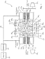
- Fig. 1 shows a drive configuration 10A for a skid steered vehicle, which includes first and second electric motors 12 L , 12 R arranged to rotatably drive first and second output shafts 14 L , 14 R .
- These output shafts 14 L , 14 R are themselves operatively coupled via respective gear connections to drive members 16 L , 16 R on opposite sides of the vehicle for driving vehicle tracks on each side of the vehicle.
- the rotor of the first electric motor 12 L is arranged to drivingly rotate the sun gear 18 L of a first planetary gear set 20 L
- the rotor of the second electric motor 12 R is arranged to drivingly rotate the sun gear 18 R of a second planetary gear set 20 R
- the carrier gear 22 L of the first planetary gear set 20 L is rotationally fixed to the first output shaft 14 L
- the carrier gear 22 R of the second planetary gear set 20 R is rotationally fixed to the second output shaft 14 R .
- the ring gear 24 L of the first planetary gear set 20 L is meshed with top and bottom bevel gears 27, 28 such that rotating the ring gear 24 L drives rotation of the top and bottom bevel gears 27, 28 in opposite senses, whereas the ring gear 24 R of the second planetary gear set 20 R is similarly meshed with the top and bottom bevel gears 27, 28.
- the top and bottom bevel gears 27, 28 are arranged so as to be rotatable relative to the vehicle body, which will be described in more detail below. Initially however some additional components of the drive configuration 10 A will first be described.
- the first and second output shafts 14 L , 14 R are also rotationally fixed to the ring gears 26 L , 26 R of third and fourth planetary gear sets 30 L , 30 R .
- the carrier gears 32 L , 32 R of such third and fourth planetary gear sets 30 L , 30 R are connected by a cross-shaft 34 and so are rotationally fixed relative to each other; that is one cannot be rotated at a different rotational speed to the other.
- sun gears 36 L , 36 R of the third and fourth planetary gear sets 30 L , 30 R are operatively coupled to the top and bottom bevel gears 27, 28 via additional bevel gear connections 38, 40 such that rotation of the top and bottom bevel gears 27, 28 causes rotation of the sun gears 36 L , 36 R in opposite senses.
- the arrangement of gears between the first and second electric motors 12 L , 12 R (i.e. the differential denoted 13) is provided to assist skid steering without the need for a dedicated steer motor.
- the differential 13 enables braking power to be transferred from the slower running (inside) track to the faster (outside) track and how this is achieved is described below.
- the differential 13 enables power to be mechanically transferred across it.
- the driving speeds of the first and second electric motors 12 L , 12 R are adjusted such that one rotates faster than the other. For instance to skid steer to the left the rotational speed of the left-side drive member 16 L is reduced, whereas the rotational speed of the right-side drive member 16 R is increased.
- Running the first and second electric motors 12 L , 12 R at different speeds to cause skid steering provides that different magnitudes of torque are exerted on the ring gears 24 L , 24 R of the first and second planetary gear sets 20 L , 20 R .
- carrier gears 32 L , 32 R are rotationally linked by the cross-shaft 34 in order to equalise torque and power across each of the respective third and fourth planetary gear sets 30 L , 30 R while the sun gears 36 L , 36 R are rotating in opposite senses, one of the ring gears 26 L , 26 R is caused to rotate faster than the other.
- the above described differential 13 is configured so that during a left turn skid steering operation the ring gear 26 R which is caused to increase in rotational speed contributes to driving rotation of the outer output shaft 14 R and thereby the outer track, whereas the ring gear 26 L which is caused to decrease in rotational speed contributes to driving rotation of the inner output shaft 14 L and thereby the inner track. Moreover braking power for slowing down the inside track during a skid steer turning operation is transferred, via the cross-shaft 34, to the outside track for increasing its speed.
- torque and power required to both cause and maintain a difference in rotational speed of the two drive members 16 L , 16 R comes from running the first and second motors 12 L , 12 R at different speeds and transferring braking power from the slower running (inside) track to the faster running (outside) track.
- the differential 13 provides that the difference between rotational speeds of the two electric motors 12 L , 12 R will be greater than the difference between rotational speeds of the drive members 16 L , 16 R . It will thus be appreciated therefore, upon considering torque specifically, that due to the differential 13 the difference between the magnitudes of torque exerted by the output shafts 14 L , 14 R is bigger than the difference between the magnitudes of torque output by the first and second electric motors 12 L , 12 R running at different speeds. In other words the difference between the torque outputs of the two electric motors 12 L , 12 R operating at different speeds is amplified by the differential 13 and output via the output shafts 14 L , 14 R to cause tracks on opposite sides of the vehicle to run at different speeds.
- the electric motors 12 L , 12 R of the drive configuration 10 A depicted in Fig. 1 are powered in a series-hybrid manner in which a combustion engine 35 drives a generator 37 for powering the motors 12 L , 12 R via an electric bus 39.
- Skid steered vehicles configured to be exclusively driven by electric motors in such a manner are more suited for driving at low speeds than higher speeds due to the typical torque/speed relationship of electric motors, whereby torque output decreases with increased rotational speed as illustrated by the line T ELECTRIC MOTOR in Fig. 3 .
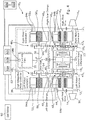
- a skid steered vehicle can though be enhanced by providing it with a drive configuration 10 B of the type illustrated in Fig. 4 in which a combustion engine 35 is mechanically coupled to the vehicle drive members 16 L , 16 R .
- the first and second electric motors 12 L , 12 R in Fig. 4 can, however, be rotationally coupled to the sun gears 18 L , 18 R either directly or via respective additional planetary gear sets 43 L , 43 R depending on the position of the respective slider members 44 L , 44 R , whereby the additional planetary gear sets act as gear reduction units.
- the slider position selected will depend on the magnitude of torque required to be exerted on the first and second output shafts 14 L , 14 R by the first and second electric motors 12 L , 12 R at a given driving speed.
- respective gears 46 L , 46 R operatively connect the sun gears 18 L , 18 R of the first and second planetary gear sets 20 L , 20 R - which form part of the differential 13 - with fifth and sixth additional planetary gear sets 48 L , 48 R .
- gears 46 L , 46 R mesh with respective external gears 45 L , 45 R attached to the internal ring gears 49 L , 49 R of the fifth and sixth planetary gear sets 48 L , 48 R .
- the sun gears 50 L , 50 R however of the fifth and sixth planetary gear sets 48 L , 48 R are arranged to be rotatably driven by third and fourth electric motors 52 L , 52 R respectively.
- the carrier gears 54 L , 54 R of the fifth and sixth planetary gear sets 48 L , 48 R are connected by a drive-shaft 56 and are rotationally fixed relative to each other; that is one cannot be rotated at a different rotational speed to the other.
- the aforementioned combustion engine 35 is mechanically coupled to the drive-shaft 56 for rotating it (and thus the carrier gears 54 L , 54 R ) via a bevel gear arrangement 58. Orienting the engine 35 at 90 degrees to the common drive-shaft 56 has packaging benefits if width of the system is a concern.
- Each of the electric motors 12 L , 12 R , 52 L , 52 R are separately connected to an electric bus 39 and are capable of drawing power from, or providing power to, a battery 60 depending on whether the respective electric motor is operated in motor mode (when the rotor drives rotation of a connected sun gear) or generator mode (when a connected sun gear drives rotation of the rotor).
- the rotational speeds and thereby torques of the first to fourth electric motors 12 L , 12 R , 52 L , 52 R can be chosen such that the engine 35 can be operated at a speed which optimises a particular operational parameter thereof (e.g. optimum efficiency, power or torque).
- a particular operational parameter thereof e.g. optimum efficiency, power or torque.
- the engine 35 can be controlled to continue operating at that speed and will provide the propulsion torque and power
- the first and second electric motors 12 L , 12 R can be controlled to operate at the required speed, torque and power to provide the correct output to the transmission so as to cause opposing vehicle tracks to run at different speed (depending on the required direction of turning).
- the third and fourth electric motors 52 L , 52 R can be controlled to operate as required to balance the power and torque within the system during steering.
- the first to fourth electric motors 12 L , 12 R , 52 L , 52 R can be controlled to provide that the vehicle drive members 16 L , 16 R are driven at the appropriate speed with the appropriate torque depending on the circumstances and user demand (i.e. whether the vehicle is to be maintained at constant speed, whether the vehicle is to be accelerated, whether the vehicle is to be driven along a slope or whether the vehicle is to undergo skid steering etc.).
- the engine 35 can be controlled to be driven at ⁇ P, MAX (see the line P ENGINE in Fig.3 illustrating the typical relationship between power output of a combustion engine and rotational speed thereof). While the engine is driven at such a speed, the first to fourth electric motors 12 L , 12 R , 52 L , 52 R can be controlled to provide that the vehicle drive members 16 L , 16 R are driven at the appropriate speed with the appropriate torque depending on the circumstances and user demand (i.e. whether the vehicle is to be maintained at constant speed, whether the vehicle is to be accelerated, whether the vehicle is to be driven along a slope or whether the vehicle is to undergo skid steering etc.).
- the engine 35 can be controlled to be driven at ⁇ T, MAX (see the line T ENGINE in Fig.3 illustrating the typical relationship between torque output of a combustion engine and rotational speed thereof). While the engine is driven at such a speed, the first to fourth electric motors 12 L , 12 R , 52 L , 52 R can be controlled to provide that the vehicle drive members 16 L , 16 R are driven at the appropriate speed with the appropriate torque depending on the circumstances and user demand (i.e. whether the vehicle is to be maintained at constant speed, whether the vehicle is to be accelerated, whether the vehicle is to be driven along a slope or whether the vehicle is to undergo skid steering etc.).
- a computer 62 is connected to rotational speed sensors 64a to 64e for receiving information indicative of the rotational speed and direction of each of the first to fourth electric motors 12 L , 12 R , 52 L , 52 R and the engine 35.
- the computer 62 is also connected to a plurality of sensors 66a to 66n, some of which transmit to the computer 62 information indicative of user input for controlling vehicle motion (e.g. sensors for generating information indicative of steering wheel manipulation, accelerator pedal manipulation and brake pedal manipulation or otherwise for instance) and some others of which are described in more detail below (one of which could be e.g. a tilt sensor).
- controller 62a Based on information received by the computer 62 a controller 62a thereof, in conjunction with both volatile and non-volatile memory 62b, 62c, determines the performance of each of the first to fourth electric motors 12 L , 12 R , 52 L , 52 R required to cause the desired vehicle motion while causing the engine 35 to be operated at a speed which optimises a specific parameter thereof (e.g. output power, output torque or fuel efficiency as above).
- a specific parameter thereof e.g. output power, output torque or fuel efficiency as above.
- first and second electric motors 12 L , 12 R are used to drive rotation of the output shafts 14 L , 14 R and thereby propel and steer a vehicle as heretofore described, during which time the third and fourth electric motors 52 L , 52 R operate in coast mode and the engine 35 remains off.
- the controller 62a in which the third and fourth electric motors 52 L , 52 R are energized and the combustion engine 35 is running.
- Transition from the first to the second operational mode occurs when rotational speed of at least one of the third and fourth electric motors 52 L , 52 R operating in coast mode exceeds a threshold amount S START during vehicle motion, which is determined by the controller 62a based on information generated by the rotational speed sensors 64c and 64d.
- step S1 the controller 62a determines the engine running speed required to operate at maximum engine fuel efficiency ⁇ E, MAX , which could involve obtaining such information from a lookup table stored in the non-volatile memory 62c during manufacture.
- step S2 the controller 62a transmits control information to the engine 35 for controlling it to run at ⁇ E, MAX .
- step S3 the controller 62a processes information generated by the sensors 66a to 66n for determining vehicle control information, in other words, to determine how the driver/user is controlling the vehicle (e.g. which way they are steering, whether they are applying the vehicle throttle (and to what extent) and whether the brake pedal is applied).
- step S4 based on the determined vehicle control information, knowledge of the speed at which the engine 35 is operating, and knowledge of the rotational speed and direction of each of the electric motors 12 L , 12 R , 52 L , 52 R (based on information output from the rotational speed sensors 64a to 64d) the controller 62a is able to determine appropriate rotational speeds and directions of each of the first to fourth electric motors 12 L , 12 R , 52 L , 52 R for causing the required vehicle motion and then subsequently transmitting control information to the electric motors 12 L , 12 R , 52 L , 52 R for controlling them to operate accordingly to give rise to the required vehicle motion. In doing so the controller 62a uses information stored in the non-volatile memory 62c during manufacture concerning the gearing relationships between components of the drive configuration 10 B .
- step S5 the controller 62a determines whether a pre-specified scenario has occurred based on information received from the sensors connected to the computer 62 (i.e. the rotational speed sensors 64a to 64e and other sensors 66a to 66n one of which could be a tilt sensor, a transducer operable by a user or an engine temperature sensor for instance).
- Step S5 for example could involve determining that a max-power button or otherwise has been pressed by a user; one of the sensors 66a to 66n comprising such an input device.
- step S5 Upon implementing step S5 if "no" is determined (i.e. no pre-specified scenario is detected to have occurred) the controller returns to step S3, whereas if "yes" the method continues to step S6.
- step S6 the controller 62a determines the specific engine parameter 35 to be optimised. This can involve referring to a lookup table stored in the non-volatile memory 62c during manufacture which associates respective occurrences with an engine parameter to be optimised.
- selection of a max-power button is associated with maximum engine power and information indicative of the engine operating speed at ⁇ P, MAX at which maximum power output occurs.
- step S 7 the controller 62a reads the information indicative of the engine speed required to optimise the required parameter, in this example power output.
- step S8 the controller 62a transmits control information to the engine 35 (or an engine controller thereof) for controlling it to run at the required speed, in this example ⁇ P, MAX , before returning to step S3.
- step S5 the controller 62a may determine that the aforementioned max-power button has been deselected and in response to this the engine 35 could be caused to return to running at ⁇ E, MAX , the speed at which maximum engine fuel efficiency is realised.
- step S5 a variety of other situations could be detected to have occurred upon implementing step S5 depending on how the vehicle is configured at manufacture to respond to certain situations. For example if a user is detected to have stomped on an accelerator pedal abruptly rather than squeeze it gently, determined based on output from one or more of the sensors 66a to 66n, the controller 62a could in response cause the engine 35 to begin operating at maximum power output. In another example if the vehicle is detected to be on an inclined surface (one or more of the sensors 66a to 66n could be a tilt sensor) and losing speed above a threshold rate then the controller 62a could in response cause the engine 35 to be operated at ⁇ T , the speed at which maximum torque output occurs.
- the controller 62a could in response restrict the engine 35 from being operated at speeds other than ⁇ E, MAX , the speed at which maximum engine fuel efficiency is realised.
- the controller 62a could in response control the engine 35 to be operated in a low speed mode until it cools below a pre-specified temperature, whereby such a low speed need not necessarily be associated with a peak in one or other operational parameters of the engine 35.
- a variety of other situations could be detected to have occurred upon implementing step S5 depending on how the vehicle is configured at manufacture to respond to certain situations.
- step S5 the controller 62a could, in the background, monitor the occurrence of a scenario specified in information pre-stored in the non-volatile memory 62c during manufacture and if such a scenario is detected a flag or other indicator could be stored in the volatile memory 62b that is subsequently acknowledged when step S5 is implemented and appropriate action taken based on what scenario the flag is indicative of.
- Different scenarios could have differing levels of priority such that in subsequent steps S6 to S8 action is taken to account for occurrence of the detected scenario having the highest priority, unless it has been cancelled out in the meantime by other action taking place between the detected occurrence and implementation of step S5, such as deselection of the max-power button or returning to a substantially flat vehicle travelling surface etc.
- the manufacturer Upon designing a vehicle the manufacturer is free to program the computer 62 as necessary and include whatever sensors 66a to 66n are required for the controller 62a to detect the occurrence of any particular situations and to react accordingly.
- the computer 62 may be configured to monitor for and how the controller 62a might be caused to respond.
- the method illustrated in Fig. 5 can be ended at any time the controller 62a determines that the vehicle could be driven in a user requested manner using solely the first and second electric motors 12 L , 12 R , whereby upon ending the method the third and fourth electric motors 52 L , 52 R return to operating in coast mode and the engine 35 is switched off.
- the drive configuration 10 B in Fig. 4 will provide propulsion power and, due to provision of the heretofore described differential 13, cross transfer of regenerative steering power. It is envisioned that the drive configuration 10 B illustrated in Fig. 4 can be provided as a single unit and then retrofitted into existing platforms without a significant change to the existing vehicle platform structure. It is to be noted however that use of the specific differential 13 heretofore described is not strictly necessary and other types of differential could be used instead provided that it is capable of providing cross transfer of regenerative steering power, or in other words, provided it is capable of transferring braking power from the inside vehicle track during skid steering to the outside vehicle track.
- Fig. 6 schematically illustrates a drive configuration 10 C similar to that in Fig. 4 , however in Fig. 6 the rotors of the first and second electric motors 12 L , 12 R are connected directly to the first and second output shafts 14 L , 14 R . It will be recalled from the foregoing teaching however that the rotors could instead be connected to the first and second output shafts 14 L via a gear reduction unit comprising at least one planetary gear set 43 L , 43 R ., wherein the gear reduction unit could include gear selection functionality 44 L , 44 R .
- the differential 13 need not necessarily have a specific structure provided that it is capable of transferring braking power from the inside vehicle track during skid steering to the outside vehicle track.
- the differential 13 may in some embodiments require the use of one or more steering motors which are denoted 68 in Fig. 6 and are merely optional depending on the specific differential arrangement used.
- the engine 35 could be mechanically coupled to the drive-shaft 56 in different ways, for example in the manner of the drive configuration 10 D in Fig. 7 with all other features being similar to those already described in connection with the drive configuration 10 B .
- the total output torque and power of the engine 35 will be split between the left and right side.
- power and torque out of the right side of the engine 35 will be higher than on the left output of the engine 35.
- power and torque out of the left side of the engine 35 will be higher than on the right output of the engine 35.
- the first to fourth electric motors 12 L , 12 R , 52 L , 52 R will be controlled to collectively balance the power and torque throughout the system while the engine 35 is operated at a particular speed which optimises an operational parameter thereof in the manner heretofore described.
- the engine may only cooperate with a single electric motor such as in the drive configuration embodiment 110 illustrated in Fig 8 , in which all features similar to those heretofore described are denoted with like reference numerals increased by 100.
- the engine 135 is connected to the carrier gear of the planetary gear set 148, whereas the electric motor 152 is connected to the sun gear thereof and the ring gear is in a torque connection with a cross shaft 170 of a differential 113.
- This cross shaft 170 is connected to the carrier gears of planetary gear sets 172 L , 172 R located on opposite sides of the differential 130.
- the sun gear of one of the planetary gear sets 172 L , 172 R is in a torque connection with steering motors 168, whereas the ring gears of both planetary gear sets 172 L , 172 R are in a torque connection with output shafts 114 L , 114 R on opposite sides of the drive configuration, which, are in a torque connection with vehicle drive members 116 L , 116 R (e.g. sprockets for engaging vehicle tracks) on opposite sides of the vehicle.
- First and second electric motors 112 L , 112 R are also arranged in a torque connection with the output shafts 114 L , 114 R for enabling the vehicle drive members 116 L , 116 R to be rotatably driven.
- the drive configuration 110 is additionally arranged such that torque flowing from the electric motors 112 L , 112 R and the differential 130 in the direction of the output shafts 114 L , 114 R is required to flow through a gear reduction unit 143 comprising a plurality of planetary gear sets arranged in series with gear selection functionality 144 (i.e. sliders as heretofore described for selecting how many planetary gear sets torque flows through in use). Moreover, torque flowing from the differential 113 in the direction of the output shafts 114 L , 114 R flows through the outermost planetary gear set of the gear reduction unit 143, whereas the sliders can be moved to change how many planetary gear sets torque flowing from the first and second electric motors 112 L , 112 R cascades through.
- gear reduction unit 143 comprising a plurality of planetary gear sets arranged in series with gear selection functionality 144 (i.e. sliders as heretofore described for selecting how many planetary gear sets torque flows through in use).
- gear selection functionality 144 i.e.
- the first and second electric motors 112 L , 112 R operate at the same speed.
- Energising the steering motors 168 during vehicle propulsion solely by the first and second electric motors electric motors 112 L , 112 R will impart a difference to the rotational speeds of the ring gears of the planetary gear sets 172 L , 172 R of the differential 113.
- the output shafts 114 L , 114 R , drive members 116 L , 116 R and thereby vehicle tracks will be driven at different speeds giving rise to skid steering in a direction dependent on the direction of rotation of the steering motors 168.
- differential cross shaft 170 being rotationally fixed to the carrier gears on opposite sides thereof - that is the carrier gears are restricted to rotating at the same rotational speed - braking power for slowing down the inside track during a skid steering operation is transferred to the outside track for increasing its driving speed.
- a threshold speed S START determined by the controller 162a based on output from the rotational speed sensor 164c the vehicle transitions into a second operational mode.
- the engine 135 is started, the electric motor 152 is energised and performance of drive configuration components is controlled on the basis of instructions pre-stored on the vehicle during manufacture similarly as heretofore described.
- a computer 162 is connected to rotational speed sensors 164a to 164f for receiving information indicative of the rotational speed and direction of each of the electric motors 112 L , 112 R and 152, the steering motors 168, 168 and the engine 135.
- the computer 162 is also connected to a plurality of sensors 166a to 166n similarly as heretofore described for receiving information indicative of user input for controlling vehicle motion (e.g. sensors for generating information indicative of steering wheel manipulation, accelerator pedal manipulation and brake pedal manipulation or otherwise for instance) and other circumstances (e.g. tilt or engine temperature etc.).
- sensors 166a to 166n similarly as heretofore described for receiving information indicative of user input for controlling vehicle motion (e.g. sensors for generating information indicative of steering wheel manipulation, accelerator pedal manipulation and brake pedal manipulation or otherwise for instance) and other circumstances (e.g. tilt or engine temperature etc.).
- controller 162a Based on information received by the computer 162 a controller 162a thereof, in conjunction with both volatile and non-volatile memory 162b, 162c, determines the performance of each of the electric motors 112 L , 112 R and 152 and the steering motors 168 required to cause the desired vehicle motion while causing the engine 135 to be operated at a particular rotational speed which, optionally depending on the circumstances, is associated with a peak in an operational parameter of the engine 135.
- the manufacturer is free to program the computer 162 as necessary and include whatever sensors 166a to 166n are required for the controller 162a to detect the occurrence of any particular situations and to react accordingly.
- Fig. 9 illustrates another drive configuration embodiment in which the engine cooperates with a single electric motor, in which all features similar to those heretofore described are denoted with like reference numerals again increased by 100.
- the engine 235 is connected to the carrier gear of the planetary gear set 248, whereas the electric motor 252 is connected to the sun gear thereof and the ring gear is in a torque connection with a common ring gear of a differential 213. This common ring gear cooperates with opposing sets of planetary gears.
- the sun gear of one side of the differential 213 is in a torque connection with steering motors 268, whereas the carrier gears on both sides of the differential 213 are in a torque connection with output shafts 214 L , 214 R on opposite sides of the drive configuration, which, are in a torque connection with vehicle drive members 216 L , 216 R (e.g. sprockets for engaging vehicle tracks) on opposite sides of the vehicle.
- vehicle drive members 216 L , 216 R e.g. sprockets for engaging vehicle tracks
- First and second electric motors 212 L , 212 R are also arranged in a torque connection with the output shafts 214 L , 214 R for enabling the vehicle drive members 216 L , 216 R to be rotatably driven, although torque flowing from the electric motors 212 L , 212 R in the direction of the output shafts 214 L , 214 R is required to flow through a gear reduction unit 243 comprising a plurality of planetary gear sets arranged in series with gear selection functionality 244 (i.e. sliders for selecting how many planetary gear sets torque flows through in use). The sliders can be moved to change how many planetary gear sets torque flowing from the first and second electric motors 212 L , 212 R cascades through.
- the first and second electric motors 212 L , 212 R operate at the same speed.
- Energising the steering motors 268 during vehicle propulsion solely by the first and second electric motors 212 L , 212 R will impart a difference to the rotational speeds of the carrier gears on opposite sides of the differential 213.
- the output shafts 214 L , 214 R , drive members 216 L , 216 R and thereby vehicle tracks will be driven at different speeds giving rise to skid steering in a direction dependent on the direction of rotation of the steering motors 268.
- due to the common ring gear between features on opposite sides of the differential 213 braking power for slowing down the inside track during a skid steering operation is transferred to the outside track for increasing its driving speed.
- a computer 262 is connected to rotational speed sensors 264a to 264f for receiving information indicative of the rotational speed and direction of each of the electric motors 212 L , 212 R and 252, the steering motors 268, 268 and the engine 235.
- the computer 262 is also connected to a plurality of sensors 266a to 266n similarly as heretofore described for receiving information indicative of user input for controlling vehicle motion (e.g.
- controller 262a determines the performance of each of the electric motors 212 L , 212 R and 252 and the steering motors 268 required to cause the desired vehicle motion while causing the engine 235 to be operated at a particular rotational speed which, optionally depending on the circumstances, optimises an operational parameter of the engine 255.
- the manufacturer is free to program the computer 262 as necessary and include whatever sensors 266a to 266n are required for the controller 262a to detect the occurrence of any particular situations and to react accordingly.
- Fig. 10 schematically illustrates a drive configuration 310 similar to that in Fig. 9 in which all features similar to those heretofore described are denoted with like reference numerals again increased by 100.
- the rotors of the first and second electric motors 312 L , 312 R are connected directly to the first and second output shafts 314 L , 314 R .
- the rotors could instead be connected to the first and second output shafts 314 L via a gear reduction unit comprising at least one planetary gear set., wherein the gear reduction unit could include gear selection functionality (e.g. the gear reduction unit 243 in Fig.
- Fig. 10 also clearly illustrates that the differential 313 need not necessarily have a specific structure provided that it is capable of transferring braking power from the inside vehicle track during skid steering to the outside vehicle track; and provided that the planetary gearset 348 is in a torque connection with a common feature linking components on one side of the differential 313 with those on the other side thereof.
- a differential 313 may be provided in the absence of steering motors, such as the differential described in connection with Fig. 4 .
- the differential 313 maybe arranged in conjunction with steering motors, such as the differentials described in connection with Figs. 8 and 9 .
- the steering motors which are denoted 368 in Fig. 10 are thus merely optional depending on the specific differential arrangement used.
- two or more engines could be connected in parallel to the drive-shaft 56 in Fig. 4 if more power is required.
- the differential described in connection with Figs. 1 and 4 need not necessarily have the exact same configuration as heretofore described, provided that it is still capable of enabling vehicle drive members on opposite sides of a vehicle to be rotatably driven a different speeds and is still capable of transferring braking power from one side of a drive configuration to the other during a skid steering operation.
- the top and bottom bevel gears 27, 28 could be operatively coupled to the sun gears 36 L , 36 R in various different ways that will be apparent to persons skilled in the art upon reading the foregoing disclosure.
- respective input/output features of the third and fourth planetary gear sets 30 L , 30 R i.e. sun gear, ring gear, carrier
- any of its respective inputs/output could be operatively coupled to the first output shaft 14 L
- another input/output could be operatively coupled to the top and bottom bevel gears 27, 28 and the remaining input/output could be could rotationally fixed relative to the corresponding feature of the fourth planetary gear set 30 R .
- respective inputs/outputs thereof i.e. sun gear, ring gear, carrier
- respective inputs/outputs thereof could be arranged differently.
- any of its respective inputs/outputs could be operatively coupled to the motor 52 L
- another of its inputs/outputs could be operatively coupled to the external gear 45 L and the remaining of its inputs/outputs could be could rotationally fixed to the corresponding feature of the sixth planetary gearset 48 R via the drive-shaft 56.
- gear selection functionality i.e. sliders 44 for changing how many planetary gear sets torque flows through in use
- the heretofore described functionality can include the additional steps of determining an appropriate gear (i.e. appropriate slider positions) and controlling the position of respective sliders to select the appropriate gear.
- step S 4 in Fig. 5 could include sub-steps for implementing such functionality or alternatively such functionality could be performed in a step S3a preceding step S4.
- the positions of sliders can be changed whether by manual user gear selection upon manipulating a gear stick for instance if operating in a "manual" mode, or alternatively by automatic control if operating in an "automatic" mode.
- Steps S1 and S2 in Fig. 5 need not necessarily involve controlling the engine 35 to operate a maximum fuel efficiency and instead could involve controlling the engine 35 to be operated at a default speed, which could be selected by a user.
- steps S6 to S8 in Fig. 5 could, more broadly, instead of causing the engine to operate at a speed which optimises a particular operational parameter thereof, cause it to be controlled at a rotational speed dependant on the pre-specified scenario detected to have occurred and the corresponding required result (i.e. how the computer is programmed to react to that scenario).
- the controller of a drive configuration may control operation of various components even when the heretofore mentioned threshold rotational speed S START has not been exceeded. For example when propelling a vehicle solely using first and second electric motors (e.g. the motors denoted 12L and 12R in Fig. 4 ) if the controller determines that battery power is low (e.g. if the battery 60 in Fig. 4 is charged below a threshold amount) then the controller can take action to charge the battery up. For example it can, in response to such a determination, cause switching on of the combustion engine such that it drives rotation of one or more electric motors (e.g. the electric motors denoted 52L, 52R in Fig. 4 ) in generator mode for charging the battery; whereas at the same time the other electric motors (e.g. the motors denoted 12L and 12R in Fig. 4 ) are controlled so as to give rise to intended vehicle motion.
- first and second electric motors e.g. the motors denoted 12L and 12R in
Landscapes
- Engineering & Computer Science (AREA)
- Mechanical Engineering (AREA)
- Transportation (AREA)
- Chemical & Material Sciences (AREA)
- Combustion & Propulsion (AREA)
- Automation & Control Theory (AREA)
- General Engineering & Computer Science (AREA)
- Electric Propulsion And Braking For Vehicles (AREA)
- Retarders (AREA)
- Hybrid Electric Vehicles (AREA)
- Arrangement And Driving Of Transmission Devices (AREA)
Applications Claiming Priority (4)
| Application Number | Priority Date | Filing Date | Title |
|---|---|---|---|
| GBGB1608745.4A GB201608745D0 (en) | 2016-05-18 | 2016-05-18 | Drive configuration for a skid steered vehicle |
| GBGB1621968.5A GB201621968D0 (en) | 2016-05-18 | 2016-12-22 | Drive configurations for skid steered vehicles |
| PCT/EP2017/056310 WO2017198356A1 (fr) | 2016-05-18 | 2017-03-16 | Configurations d'entraînement pour véhicules à direction différentielle |
| EP17711642.3A EP3458294B1 (fr) | 2016-05-18 | 2017-03-16 | Configurations d'entraînement pour véhicules à direction différentielle |
Related Parent Applications (1)
| Application Number | Title | Priority Date | Filing Date |
|---|---|---|---|
| EP17711642.3A Division EP3458294B1 (fr) | 2016-05-18 | 2017-03-16 | Configurations d'entraînement pour véhicules à direction différentielle |
Publications (3)
| Publication Number | Publication Date |
|---|---|
| EP3763555A2 true EP3763555A2 (fr) | 2021-01-13 |
| EP3763555A3 EP3763555A3 (fr) | 2021-05-05 |
| EP3763555B1 EP3763555B1 (fr) | 2025-09-10 |
Family
ID=56320604
Family Applications (2)
| Application Number | Title | Priority Date | Filing Date |
|---|---|---|---|
| EP17711642.3A Active EP3458294B1 (fr) | 2016-05-18 | 2017-03-16 | Configurations d'entraînement pour véhicules à direction différentielle |
| EP20193200.1A Active EP3763555B1 (fr) | 2016-05-18 | 2017-03-16 | Configurations d'entraînement pour véhicules à direction à glissement |
Family Applications Before (1)
| Application Number | Title | Priority Date | Filing Date |
|---|---|---|---|
| EP17711642.3A Active EP3458294B1 (fr) | 2016-05-18 | 2017-03-16 | Configurations d'entraînement pour véhicules à direction différentielle |
Country Status (11)
| Country | Link |
|---|---|
| US (1) | US10836427B2 (fr) |
| EP (2) | EP3458294B1 (fr) |
| KR (1) | KR102253206B1 (fr) |
| CN (1) | CN109311383B (fr) |
| AU (2) | AU2017265390B2 (fr) |
| CA (1) | CA3023783C (fr) |
| ES (1) | ES2819840T3 (fr) |
| GB (2) | GB201608745D0 (fr) |
| IL (1) | IL262939B (fr) |
| PL (1) | PL3763555T3 (fr) |
| WO (1) | WO2017198356A1 (fr) |
Families Citing this family (16)
| Publication number | Priority date | Publication date | Assignee | Title |
|---|---|---|---|---|
| DE102018131286A1 (de) * | 2018-12-07 | 2020-06-10 | Schaeffler Technologies AG & Co. KG | Antriebseinheit für ein hybrides Kraftfahrzeug; Antriebsstrang sowie Verfahren zum Betreiben der Antriebseinheit |
| US11066074B2 (en) * | 2019-08-07 | 2021-07-20 | Caterpillar Inc. | Control of an engine of a machine based on detected load requirements of the machine |
| KR102896844B1 (ko) | 2020-01-07 | 2025-12-04 | 삼성전자주식회사 | 라이다 장치 및 그 동작 방법 |
| GB2591095B (en) * | 2020-01-14 | 2023-11-29 | Qinetiq Ltd | A drive system for a skid steered vehicle |
| GB2624308B (en) | 2020-01-14 | 2024-10-02 | Qinetiq Ltd | A drive system for a skid steered vehicle |
| DE102020201473A1 (de) * | 2020-02-06 | 2021-08-12 | Zf Friedrichshafen Ag | Lenkschaltgetriebe für Kettenfahrzeuge als Parallelhybrid |
| US12024027B2 (en) | 2020-07-27 | 2024-07-02 | Kinetics Drive Solutions, Inc. | Electro-mechanical cross steer drive device for a vehicle |
| KR102802000B1 (ko) * | 2020-07-27 | 2025-05-02 | 키네틱스 드라이브 솔루션스 아이엔씨. | 차량용 전자-기계식 교차 조향 구동 장치 |
| SE546763C2 (en) * | 2021-03-24 | 2025-02-18 | Borgwarner Sweden Ab | Electric drive module |
| US11529869B2 (en) | 2021-04-09 | 2022-12-20 | Dana Heavy Vehicle Systems Group, Llc | Electric drive axle system and operating method |
| DE102021204245A1 (de) * | 2021-04-28 | 2022-11-03 | Dana Graziano S.R.L. | Hybridantriebseinheit |
| KR102591847B1 (ko) * | 2021-05-27 | 2023-10-20 | 현대로템 주식회사 | 하이브리드 궤도차량용 전자기계식 변속기 |
| DE102021006011A1 (de) * | 2021-12-06 | 2023-06-07 | Mercedes-Benz Group AG | Elektrisches Antriebssystem für ein Kraftfahrzeug |
| CN115009002B (zh) * | 2022-04-29 | 2024-11-08 | 东风商用车有限公司 | 一种商用车用双行星多电机混联无级变速传动装置 |
| US12558950B2 (en) | 2023-04-21 | 2026-02-24 | Saudi Arabian Oil Company | Integrated internal combustion electric motor (ICEM) concept for hybrid and plug-in hybrid vehicle application |
| US11897474B1 (en) | 2023-04-25 | 2024-02-13 | Cnh Industrial America Llc | Fuel efficient operation mode |
Citations (1)
| Publication number | Priority date | Publication date | Assignee | Title |
|---|---|---|---|---|
| US20150210266A1 (en) * | 2014-01-30 | 2015-07-30 | Byd Company Limited | Vehicle and drive control method for the same |
Family Cites Families (31)
| Publication number | Priority date | Publication date | Assignee | Title |
|---|---|---|---|---|
| US5195600A (en) * | 1991-07-11 | 1993-03-23 | General Electric Company | Electric drive system for track-laying vehicles |
| JPH1081152A (ja) * | 1996-09-11 | 1998-03-31 | Yanmar Agricult Equip Co Ltd | クローラ式走行装置の差動装置 |
| JPH11240347A (ja) * | 1998-02-24 | 1999-09-07 | Honda Motor Co Ltd | 車両の左右輪間の連結装置 |
| US7000717B2 (en) * | 2001-10-23 | 2006-02-21 | The Timken Company | Output power split hybrid electric drive system |
| US20030119620A1 (en) * | 2001-12-21 | 2003-06-26 | Caterpillar Inc. | Variable and differential output drive system |
| JP2004276813A (ja) * | 2003-03-18 | 2004-10-07 | Yanmar Agricult Equip Co Ltd | 作業車 |
| DE10316862A1 (de) * | 2003-04-11 | 2004-10-21 | Deere & Company, Moline | Antriebssystem für Fahrzeuge |
| DE10344711A1 (de) * | 2003-09-26 | 2005-04-14 | Zf Friedrichshafen Ag | Elektrisches Antriebssystem für ein Fahrzeug mit Rutschlenkung |
| JP4292086B2 (ja) * | 2004-01-13 | 2009-07-08 | ヤンマー株式会社 | 除雪機の変速装置 |
| DE102004009030B4 (de) * | 2004-02-23 | 2020-07-23 | Renk Aktiengesellschaft | Antrieb für ein Kettenfahrzeug |
| KR101028401B1 (ko) * | 2005-04-11 | 2011-04-13 | 현대다이모스(주) | 하이브리드 전기 자동차의 동력 전달 장치 |
| DE102005035824A1 (de) * | 2005-07-30 | 2007-02-01 | Renk Ag | Hybridantrieb für ein Kraftfahrzeug |
| GB0600154D0 (en) * | 2006-01-06 | 2006-02-15 | Qinetiq Ltd | Controlled differential |
| JP4631784B2 (ja) * | 2006-04-05 | 2011-02-16 | トヨタ自動車株式会社 | 車両用駆動力配分装置 |
| JP2008049867A (ja) * | 2006-08-25 | 2008-03-06 | Yanmar Co Ltd | クローラ式作業車両 |
| WO2008048477A2 (fr) | 2006-10-13 | 2008-04-24 | The Ohio State University Research Foundation | Chaîne cinématique, véhicule et procédés |
| GB0705845D0 (en) * | 2007-03-27 | 2007-05-02 | Qinetiq Ltd | Controlled differential |
| US8844665B2 (en) * | 2007-12-27 | 2014-09-30 | Swissauto Powersport Llc | Skid steered all terrain vehicle |
| JP5424674B2 (ja) * | 2009-03-09 | 2014-02-26 | ヤンマー株式会社 | 作業機 |
| JP2010209990A (ja) * | 2009-03-09 | 2010-09-24 | Yanmar Co Ltd | 作業機 |
| GB0915305D0 (en) * | 2009-09-03 | 2009-10-07 | Qinetiq Ltd | Gear reduction and coupling assembly |
| GB0915306D0 (en) * | 2009-09-03 | 2009-10-07 | Qinetiq Ltd | Final drive assembly |
| DE102010051058A1 (de) | 2010-11-11 | 2012-05-16 | Schaeffler Technologies Gmbh & Co. Kg | Antriebseinheit |
| GB201104917D0 (en) * | 2011-03-24 | 2011-05-04 | Qinetiq Ltd | Gear reduction mechanism |
| CN102673643A (zh) | 2012-01-04 | 2012-09-19 | 河南科技大学 | 提高履带车辆液压机械差速转向系统性能的方法 |
| GB201311628D0 (en) | 2013-06-28 | 2013-08-14 | Qinetiq Ltd | Drive configurations for skid steered vehicles |
| JP6142842B2 (ja) | 2014-05-12 | 2017-06-07 | トヨタ自動車株式会社 | 車両の制御装置 |
| US20150337937A1 (en) * | 2014-05-23 | 2015-11-26 | GM Global Technology Operations LLC | Torque vectoring hybrid transaxle |
| DE102014007940A1 (de) * | 2014-05-24 | 2015-11-26 | Audi Ag | Kraftfahrzeug |
| US9874266B2 (en) * | 2014-09-10 | 2018-01-23 | Byd Company Limited | Power transmission system and vehicle comprising the same |
| US9321451B2 (en) * | 2014-09-30 | 2016-04-26 | Ford Global Technologies, Llc | Managing ring gear torque in a hybrid electric vehicle to increase available wheel torque |
-
2016
- 2016-05-18 GB GBGB1608745.4A patent/GB201608745D0/en not_active Ceased
- 2016-12-22 GB GBGB1621968.5A patent/GB201621968D0/en not_active Ceased
-
2017
- 2017-03-16 EP EP17711642.3A patent/EP3458294B1/fr active Active
- 2017-03-16 CA CA3023783A patent/CA3023783C/fr active Active
- 2017-03-16 AU AU2017265390A patent/AU2017265390B2/en active Active
- 2017-03-16 KR KR1020187036232A patent/KR102253206B1/ko active Active
- 2017-03-16 US US16/303,127 patent/US10836427B2/en active Active
- 2017-03-16 ES ES17711642T patent/ES2819840T3/es active Active
- 2017-03-16 PL PL20193200.1T patent/PL3763555T3/pl unknown
- 2017-03-16 WO PCT/EP2017/056310 patent/WO2017198356A1/fr not_active Ceased
- 2017-03-16 CN CN201780030672.9A patent/CN109311383B/zh not_active Expired - Fee Related
- 2017-03-16 EP EP20193200.1A patent/EP3763555B1/fr active Active
-
2018
- 2018-11-12 IL IL262939A patent/IL262939B/en unknown
-
2023
- 2023-03-01 AU AU2023201255A patent/AU2023201255B2/en active Active
Patent Citations (1)
| Publication number | Priority date | Publication date | Assignee | Title |
|---|---|---|---|---|
| US20150210266A1 (en) * | 2014-01-30 | 2015-07-30 | Byd Company Limited | Vehicle and drive control method for the same |
Also Published As
| Publication number | Publication date |
|---|---|
| EP3458294B1 (fr) | 2020-09-02 |
| AU2023201255B2 (en) | 2023-06-08 |
| EP3763555A3 (fr) | 2021-05-05 |
| CN109311383B (zh) | 2022-10-04 |
| PL3763555T3 (pl) | 2026-01-26 |
| AU2023201255A1 (en) | 2023-04-06 |
| EP3763555B1 (fr) | 2025-09-10 |
| IL262939A (en) | 2018-12-31 |
| CA3023783A1 (fr) | 2017-11-23 |
| US20200331526A1 (en) | 2020-10-22 |
| ES2819840T3 (es) | 2021-04-19 |
| CN109311383A (zh) | 2019-02-05 |
| GB201608745D0 (en) | 2016-06-29 |
| KR20190005226A (ko) | 2019-01-15 |
| WO2017198356A1 (fr) | 2017-11-23 |
| CA3023783C (fr) | 2024-02-20 |
| EP3458294A1 (fr) | 2019-03-27 |
| KR102253206B1 (ko) | 2021-05-20 |
| AU2017265390A1 (en) | 2018-11-15 |
| US10836427B2 (en) | 2020-11-17 |
| AU2017265390B2 (en) | 2022-12-01 |
| GB201621968D0 (en) | 2017-02-08 |
| IL262939B (en) | 2021-09-30 |
Similar Documents
| Publication | Publication Date | Title |
|---|---|---|
| EP3763555B1 (fr) | Configurations d'entraînement pour véhicules à direction à glissement | |
| JP6477533B2 (ja) | ハイブリッド車両の制御装置 | |
| US7322896B2 (en) | Hybrid transmission | |
| CN102991329B (zh) | 混合动力作业车辆 | |
| RU2539306C2 (ru) | Способ приведения в движение сочлененного гусеничного транспортного средства | |
| US8485286B2 (en) | Drive configuration for skid steered vehicles | |
| KR102374192B1 (ko) | 차동 장치 | |
| JP6807914B2 (ja) | 電気自動車のためのトルクベクタリング制御を行う動力システム | |
| CN107461476A (zh) | 具有轮轴转矩矢量的差速器组件 | |
| CN112776794A (zh) | 车辆的驱动力控制装置 | |
| JP4137031B2 (ja) | 電動車両の駆動装置 | |
| CN113226891A (zh) | 一种具有冗余功能的线控独立转向机构及控制方法 | |
| US20160129905A1 (en) | Control system for hybrid vehicle | |
| JP2005306137A (ja) | ハイブリッド車両 | |
| JP2010025273A (ja) | 車両用駆動力配分装置の制御装置 | |
| JP2012158311A (ja) | 車両用駆動操舵アクチュエータ | |
| JP3906826B2 (ja) | ハイブリッド4輪駆動車の制御装置 | |
| JP2023012117A (ja) | 四輪駆動車の動力分配装置 | |
| JP7415974B2 (ja) | 動力伝達装置の制御装置、車両、および動力伝達装置の制御方法 | |
| TR2023013978A2 (tr) | Seri̇ hi̇bri̇t paletli̇ araçlar i̇çi̇n çapraz tahri̇kli̇ e-transmi̇syon | |
| CN118418693A (zh) | 动力驱动系统及车辆 |
Legal Events
| Date | Code | Title | Description |
|---|---|---|---|
| PUAI | Public reference made under article 153(3) epc to a published international application that has entered the european phase |
Free format text: ORIGINAL CODE: 0009012 |
|
| STAA | Information on the status of an ep patent application or granted ep patent |
Free format text: STATUS: THE APPLICATION HAS BEEN PUBLISHED |
|
| AC | Divisional application: reference to earlier application |
Ref document number: 3458294 Country of ref document: EP Kind code of ref document: P |
|
| AK | Designated contracting states |
Kind code of ref document: A2 Designated state(s): AL AT BE BG CH CY CZ DE DK EE ES FI FR GB GR HR HU IE IS IT LI LT LU LV MC MK MT NL NO PL PT RO RS SE SI SK SM TR |
|
| PUAL | Search report despatched |
Free format text: ORIGINAL CODE: 0009013 |
|
| AK | Designated contracting states |
Kind code of ref document: A3 Designated state(s): AL AT BE BG CH CY CZ DE DK EE ES FI FR GB GR HR HU IE IS IT LI LT LU LV MC MK MT NL NO PL PT RO RS SE SI SK SM TR |
|
| RIC1 | Information provided on ipc code assigned before grant |
Ipc: B60K 6/48 20071001AFI20210401BHEP Ipc: B62D 11/14 20060101ALI20210401BHEP Ipc: B60W 10/20 20060101ALI20210401BHEP Ipc: B60W 20/10 20160101ALI20210401BHEP Ipc: B60W 20/40 20160101ALI20210401BHEP Ipc: B60W 20/13 20160101ALI20210401BHEP Ipc: B60K 17/16 20060101ALI20210401BHEP Ipc: B60K 23/04 20060101ALI20210401BHEP Ipc: F16H 48/36 20120101ALI20210401BHEP |
|
| STAA | Information on the status of an ep patent application or granted ep patent |
Free format text: STATUS: REQUEST FOR EXAMINATION WAS MADE |
|
| 17P | Request for examination filed |
Effective date: 20210712 |
|
| RBV | Designated contracting states (corrected) |
Designated state(s): AL AT BE BG CH CY CZ DE DK EE ES FI FR GB GR HR HU IE IS IT LI LT LU LV MC MK MT NL NO PL PT RO RS SE SI SK SM TR |
|
| STAA | Information on the status of an ep patent application or granted ep patent |
Free format text: STATUS: EXAMINATION IS IN PROGRESS |
|
| 17Q | First examination report despatched |
Effective date: 20230224 |
|
| P01 | Opt-out of the competence of the unified patent court (upc) registered |
Effective date: 20230331 |
|
| RIC1 | Information provided on ipc code assigned before grant |
Ipc: B60W 10/08 20060101ALI20250203BHEP Ipc: B60W 10/06 20060101ALI20250203BHEP Ipc: B60W 30/20 20060101ALI20250203BHEP Ipc: B60W 20/00 20160101ALI20250203BHEP Ipc: B60W 10/04 20060101ALI20250203BHEP Ipc: B60K 6/485 20071001ALI20250203BHEP Ipc: F16H 48/36 20120101ALI20250203BHEP Ipc: B60K 23/04 20060101ALI20250203BHEP Ipc: B60W 10/20 20060101ALI20250203BHEP Ipc: B62D 11/14 20060101ALI20250203BHEP Ipc: B60K 6/48 20071001AFI20250203BHEP |
|
| GRAP | Despatch of communication of intention to grant a patent |
Free format text: ORIGINAL CODE: EPIDOSNIGR1 |
|
| STAA | Information on the status of an ep patent application or granted ep patent |
Free format text: STATUS: GRANT OF PATENT IS INTENDED |
|
| RAP1 | Party data changed (applicant data changed or rights of an application transferred) |
Owner name: RENK AMERICA LLC |
|
| INTG | Intention to grant announced |
Effective date: 20250410 |
|
| GRAS | Grant fee paid |
Free format text: ORIGINAL CODE: EPIDOSNIGR3 |
|
| GRAA | (expected) grant |
Free format text: ORIGINAL CODE: 0009210 |
|
| STAA | Information on the status of an ep patent application or granted ep patent |
Free format text: STATUS: THE PATENT HAS BEEN GRANTED |
|
| AC | Divisional application: reference to earlier application |
Ref document number: 3458294 Country of ref document: EP Kind code of ref document: P |
|
| AK | Designated contracting states |
Kind code of ref document: B1 Designated state(s): AL AT BE BG CH CY CZ DE DK EE ES FI FR GB GR HR HU IE IS IT LI LT LU LV MC MK MT NL NO PL PT RO RS SE SI SK SM TR |
|
| REG | Reference to a national code |
Ref country code: GB Ref legal event code: FG4D |
|
| REG | Reference to a national code |
Ref country code: CH Ref legal event code: EP |
|
| REG | Reference to a national code |
Ref country code: DE Ref legal event code: R096 Ref document number: 602017091774 Country of ref document: DE |
|
| REG | Reference to a national code |
Ref country code: IE Ref legal event code: FG4D |
|
| PG25 | Lapsed in a contracting state [announced via postgrant information from national office to epo] |
Ref country code: NO Free format text: LAPSE BECAUSE OF FAILURE TO SUBMIT A TRANSLATION OF THE DESCRIPTION OR TO PAY THE FEE WITHIN THE PRESCRIBED TIME-LIMIT Effective date: 20251210 |
|
| REG | Reference to a national code |
Ref country code: LT Ref legal event code: MG9D |
|
| PG25 | Lapsed in a contracting state [announced via postgrant information from national office to epo] |
Ref country code: FI Free format text: LAPSE BECAUSE OF FAILURE TO SUBMIT A TRANSLATION OF THE DESCRIPTION OR TO PAY THE FEE WITHIN THE PRESCRIBED TIME-LIMIT Effective date: 20250910 |
|
| REG | Reference to a national code |
Ref country code: NL Ref legal event code: MP Effective date: 20250910 |
|
| PG25 | Lapsed in a contracting state [announced via postgrant information from national office to epo] |
Ref country code: HR Free format text: LAPSE BECAUSE OF FAILURE TO SUBMIT A TRANSLATION OF THE DESCRIPTION OR TO PAY THE FEE WITHIN THE PRESCRIBED TIME-LIMIT Effective date: 20250910 |
|
| PG25 | Lapsed in a contracting state [announced via postgrant information from national office to epo] |
Ref country code: GR Free format text: LAPSE BECAUSE OF FAILURE TO SUBMIT A TRANSLATION OF THE DESCRIPTION OR TO PAY THE FEE WITHIN THE PRESCRIBED TIME-LIMIT Effective date: 20251211 |
|
| PG25 | Lapsed in a contracting state [announced via postgrant information from national office to epo] |
Ref country code: SE Free format text: LAPSE BECAUSE OF FAILURE TO SUBMIT A TRANSLATION OF THE DESCRIPTION OR TO PAY THE FEE WITHIN THE PRESCRIBED TIME-LIMIT Effective date: 20250910 |
|
| PG25 | Lapsed in a contracting state [announced via postgrant information from national office to epo] |
Ref country code: LV Free format text: LAPSE BECAUSE OF FAILURE TO SUBMIT A TRANSLATION OF THE DESCRIPTION OR TO PAY THE FEE WITHIN THE PRESCRIBED TIME-LIMIT Effective date: 20250910 |
|
| PG25 | Lapsed in a contracting state [announced via postgrant information from national office to epo] |
Ref country code: BG Free format text: LAPSE BECAUSE OF FAILURE TO SUBMIT A TRANSLATION OF THE DESCRIPTION OR TO PAY THE FEE WITHIN THE PRESCRIBED TIME-LIMIT Effective date: 20250910 |
|
| PG25 | Lapsed in a contracting state [announced via postgrant information from national office to epo] |
Ref country code: RS Free format text: LAPSE BECAUSE OF FAILURE TO SUBMIT A TRANSLATION OF THE DESCRIPTION OR TO PAY THE FEE WITHIN THE PRESCRIBED TIME-LIMIT Effective date: 20251210 |
|
| PG25 | Lapsed in a contracting state [announced via postgrant information from national office to epo] |
Ref country code: ES Free format text: LAPSE BECAUSE OF FAILURE TO SUBMIT A TRANSLATION OF THE DESCRIPTION OR TO PAY THE FEE WITHIN THE PRESCRIBED TIME-LIMIT Effective date: 20250910 |
|
| REG | Reference to a national code |
Ref country code: AT Ref legal event code: MK05 Ref document number: 1835546 Country of ref document: AT Kind code of ref document: T Effective date: 20250910 |
|
| PG25 | Lapsed in a contracting state [announced via postgrant information from national office to epo] |
Ref country code: NL Free format text: LAPSE BECAUSE OF FAILURE TO SUBMIT A TRANSLATION OF THE DESCRIPTION OR TO PAY THE FEE WITHIN THE PRESCRIBED TIME-LIMIT Effective date: 20250910 |
|
| REG | Reference to a national code |
Ref country code: CH Ref legal event code: U11 Free format text: ST27 STATUS EVENT CODE: U-0-0-U10-U11 (AS PROVIDED BY THE NATIONAL OFFICE) Effective date: 20260401 |
|
| PG25 | Lapsed in a contracting state [announced via postgrant information from national office to epo] |
Ref country code: SM Free format text: LAPSE BECAUSE OF FAILURE TO SUBMIT A TRANSLATION OF THE DESCRIPTION OR TO PAY THE FEE WITHIN THE PRESCRIBED TIME-LIMIT Effective date: 20250910 |
|
| PGFP | Annual fee paid to national office [announced via postgrant information from national office to epo] |
Ref country code: GB Payment date: 20260324 Year of fee payment: 10 |
|
| PGFP | Annual fee paid to national office [announced via postgrant information from national office to epo] |
Ref country code: DE Payment date: 20260319 Year of fee payment: 10 |
|
| PG25 | Lapsed in a contracting state [announced via postgrant information from national office to epo] |
Ref country code: AT Free format text: LAPSE BECAUSE OF FAILURE TO SUBMIT A TRANSLATION OF THE DESCRIPTION OR TO PAY THE FEE WITHIN THE PRESCRIBED TIME-LIMIT Effective date: 20250910 |
|
| PGFP | Annual fee paid to national office [announced via postgrant information from national office to epo] |
Ref country code: IT Payment date: 20260324 Year of fee payment: 10 |
|
| PG25 | Lapsed in a contracting state [announced via postgrant information from national office to epo] |
Ref country code: IS Free format text: LAPSE BECAUSE OF FAILURE TO SUBMIT A TRANSLATION OF THE DESCRIPTION OR TO PAY THE FEE WITHIN THE PRESCRIBED TIME-LIMIT Effective date: 20260110 |
|
| PGFP | Annual fee paid to national office [announced via postgrant information from national office to epo] |
Ref country code: FR Payment date: 20260323 Year of fee payment: 10 |
|
| PGFP | Annual fee paid to national office [announced via postgrant information from national office to epo] |
Ref country code: TR Payment date: 20260311 Year of fee payment: 10 |
|
| PG25 | Lapsed in a contracting state [announced via postgrant information from national office to epo] |
Ref country code: CZ Free format text: LAPSE BECAUSE OF FAILURE TO SUBMIT A TRANSLATION OF THE DESCRIPTION OR TO PAY THE FEE WITHIN THE PRESCRIBED TIME-LIMIT Effective date: 20250910 Ref country code: PT Free format text: LAPSE BECAUSE OF FAILURE TO SUBMIT A TRANSLATION OF THE DESCRIPTION OR TO PAY THE FEE WITHIN THE PRESCRIBED TIME-LIMIT Effective date: 20260112 |
|
| PGFP | Annual fee paid to national office [announced via postgrant information from national office to epo] |
Ref country code: PL Payment date: 20260302 Year of fee payment: 10 |
|
| PG25 | Lapsed in a contracting state [announced via postgrant information from national office to epo] |
Ref country code: EE Free format text: LAPSE BECAUSE OF FAILURE TO SUBMIT A TRANSLATION OF THE DESCRIPTION OR TO PAY THE FEE WITHIN THE PRESCRIBED TIME-LIMIT Effective date: 20250910 Ref country code: SK Free format text: LAPSE BECAUSE OF FAILURE TO SUBMIT A TRANSLATION OF THE DESCRIPTION OR TO PAY THE FEE WITHIN THE PRESCRIBED TIME-LIMIT Effective date: 20250910 |