EP3763564B1 - Child seat transporting system and safety part suitable for such a child seat transporting system - Google Patents
Child seat transporting system and safety part suitable for such a child seat transporting system Download PDFInfo
- Publication number
- EP3763564B1 EP3763564B1 EP20184899.1A EP20184899A EP3763564B1 EP 3763564 B1 EP3763564 B1 EP 3763564B1 EP 20184899 A EP20184899 A EP 20184899A EP 3763564 B1 EP3763564 B1 EP 3763564B1
- Authority
- EP
- European Patent Office
- Prior art keywords
- child seat
- safety part
- safety
- seat
- transporting system
- Prior art date
- Legal status (The legal status is an assumption and is not a legal conclusion. Google has not performed a legal analysis and makes no representation as to the accuracy of the status listed.)
- Active
Links
Images


Classifications
-
- B—PERFORMING OPERATIONS; TRANSPORTING
- B60—VEHICLES IN GENERAL
- B60N—SEATS SPECIALLY ADAPTED FOR VEHICLES; VEHICLE PASSENGER ACCOMMODATION NOT OTHERWISE PROVIDED FOR
- B60N2/00—Seats specially adapted for vehicles; Arrangement or mounting of seats in vehicles
- B60N2/24—Seats specially adapted for vehicles; Arrangement or mounting of seats in vehicles for particular purposes or particular vehicles
- B60N2/26—Seats specially adapted for vehicles; Arrangement or mounting of seats in vehicles for particular purposes or particular vehicles for children
- B60N2/28—Seats readily mountable on, and dismountable from, existing seats or other parts of the vehicle
- B60N2/2821—Seats readily mountable on, and dismountable from, existing seats or other parts of the vehicle having a seat and a base part
-
- B—PERFORMING OPERATIONS; TRANSPORTING
- B60—VEHICLES IN GENERAL
- B60N—SEATS SPECIALLY ADAPTED FOR VEHICLES; VEHICLE PASSENGER ACCOMMODATION NOT OTHERWISE PROVIDED FOR
- B60N2/00—Seats specially adapted for vehicles; Arrangement or mounting of seats in vehicles
- B60N2/24—Seats specially adapted for vehicles; Arrangement or mounting of seats in vehicles for particular purposes or particular vehicles
- B60N2/26—Seats specially adapted for vehicles; Arrangement or mounting of seats in vehicles for particular purposes or particular vehicles for children
- B60N2/28—Seats readily mountable on, and dismountable from, existing seats or other parts of the vehicle
- B60N2/2842—Seats readily mountable on, and dismountable from, existing seats or other parts of the vehicle adapted to carry the child, when dismounted from the vehicle
- B60N2/2845—Seats readily mountable on, and dismountable from, existing seats or other parts of the vehicle adapted to carry the child, when dismounted from the vehicle having handles
-
- B—PERFORMING OPERATIONS; TRANSPORTING
- B60—VEHICLES IN GENERAL
- B60N—SEATS SPECIALLY ADAPTED FOR VEHICLES; VEHICLE PASSENGER ACCOMMODATION NOT OTHERWISE PROVIDED FOR
- B60N2/00—Seats specially adapted for vehicles; Arrangement or mounting of seats in vehicles
- B60N2/24—Seats specially adapted for vehicles; Arrangement or mounting of seats in vehicles for particular purposes or particular vehicles
- B60N2/26—Seats specially adapted for vehicles; Arrangement or mounting of seats in vehicles for particular purposes or particular vehicles for children
- B60N2/28—Seats readily mountable on, and dismountable from, existing seats or other parts of the vehicle
- B60N2/2842—Seats readily mountable on, and dismountable from, existing seats or other parts of the vehicle adapted to carry the child, when dismounted from the vehicle
- B60N2/2848—Seats readily mountable on, and dismountable from, existing seats or other parts of the vehicle adapted to carry the child, when dismounted from the vehicle being convertible or adaptable to a preambulator, e.g. a baby-carriage or a push-chair
-
- B—PERFORMING OPERATIONS; TRANSPORTING
- B62—LAND VEHICLES FOR TRAVELLING OTHERWISE THAN ON RAILS
- B62B—HAND-PROPELLED VEHICLES, e.g. HAND CARTS OR PERAMBULATORS; SLEDGES
- B62B7/00—Carriages for children; Perambulators, e.g. dolls' perambulators
- B62B7/04—Carriages for children; Perambulators, e.g. dolls' perambulators having more than one wheel axis; Steering devices therefor
- B62B7/14—Carriages for children; Perambulators, e.g. dolls' perambulators having more than one wheel axis; Steering devices therefor with detachable or rotatably-mounted body
- B62B7/145—Carriages for children; Perambulators, e.g. dolls' perambulators having more than one wheel axis; Steering devices therefor with detachable or rotatably-mounted body the body being a rigid seat, e.g. a shell
Definitions
- the invention relates to a child seat transporting system comprising at least a safety part, a base being detachably connectable to the vehicle seat, wherein the safety part is detachably connectable to the base, the child seat transporting system further comprising a child seat being detachably connectable to the safety part, which child seat comprises at least one child seat handle to carry the child seat when disconnected from the safety part.
- the invention further relates to a safety part suitable for a child seat transporting system.
- a known child seat transporting system of Team Tex called Satellite Isofix Car Seat Group o+ comprises a base to be connected by means of Isofix connectors to a vehicle seat. On said base an outer seat can be mounted, whereas an inner child seat can be connected to the outer seat.
- Such base is known from EP1974988B1
- outer seat and inner seat are known from EP1969974B1 .
- the inner seat can directly be mounted on a frame of a stroller.
- a disadvantage of such a child seat transporting system is that the outer seat is rather bulky and can, due to its size, only be used as an intermediate structure between the inner seat and the base.
- the width of the inner seat must be so large that its longitudinal sides can be connected to supporting elements on the sides of the frame of the stroller. Due to this width the inner side is relative large and heavy to be carried by a person from the base inside a vehicle to the frame of the stroller or to some other location.
- US10028592 B1 shows a lightweight carrier with a handle which can be attached to a a car seat.
- EP1591307 shows a maxi cosi type seat which can be attached to a car seat via a base or to a frame of a stroller.
- At least one of the objects of the invention is to provide a child seat transporting system whereby the child seat can easily be carries around whilst still being suitable to be used in a vehicle and on a frame of a stroller.
- the safety part when disconnected from the the base, is detachably connectable to a frame of a stroller, whereby when the safety part with the child seat connected thereto is connected to the frame of the stroller, the child seat is detachable from the safety part, which child seat comprises two protrusions at a rear side of a back portion thereof for resting on a flat surface when used without the safety part, whilst when used with the safety part the protrusions of the child seat are inserted into blind holes of the safety part to position the child seat in the safety part and to prevent the child seat to be able to tilt with respect to the safety part.
- the width of the safety part will be so large that its longitudinal sides can be connected to supporting elements on the sides of the frame of the stroller, the width of the child seat connected to safety part can and will be smaller than by the known inner seat of EP1969974B1 .
- the safety part is used as intermediate part between the child seat and the vehicle seat, as well as intermediate part between the child seat and the frame of the stroller.
- the child seat When transporting the child seat outside the vehicle and outside the stroller, the child seat can be carried alone or connected to the safety part. If carried alone, the child seat is relative light, compact and can easily be carried around, wherein the child can still maintain the same position in the child seat and does not need to be woken up. If a more sturdy construction around the child seat is desired, the child seat connected to the safety part can carried around.
- the child seat only needs to provide a comfortable seating part for a child, whilst safety provisions required by regulations for use of the child seat in a vehicle or in a stroller will be provided by the safety part.
- Another advantage of having a safety part and a child seat is that extra functionalities can be put into the safety part, like active cooling or electronic communication, that might be heavy and bulky.
- the child seat transporting system it is possible to connect the safety part directly to the vehicle seat, wherein the child seat is connected to the safety part. It is also possible to connect the safety part via a base to the vehicle seat.
- the use of the safety part provides the child seat transporting system with a number of different possibilities to transport the child seat depending on the wishes of a user like the adult of the child.
- An embodiment of the child seat transporting system according to the invention is characterized in that the safety part comprises at an inner side thereof at least one first connector to detachably connect the child seat to the safety part, and at an outer side thereof at least one second connectors at a first and a second longitudinal side of the safety part to detachably connect the safety part to the frame of the stroller.
- each connector can be optimized for said function and purpose.
- the safety part comprises third connectors to detachably connect the safety part to the vehicle seat by means of vehicle seat belts.
- the child seat transporting system is characterized in that the child seat transporting system comprises a base being detachably connectable to the vehicle seat, wherein the safety part is detachably connectable to the base.
- Using a base to connect the safety part to the vehicle seat has the advantage that the base can be optimized at one side for the connection with the vehicle seat and at another side for the connection with the safety part.
- Such a base can be installed in one vehicle, for example the vehicle from which the safety seat must frequently be removed, whilst the safety part is directly connected to the vehicle seat of another vehicle which vehicle is incidentally used.
- Such a base also has the advantage that the safety part can easily remain in the vehicle, whilst the child seat can easily be taken out of the safety part.
- the safety part comprises at least one fourth connector to detachably connect the safety part to the to the base.
- Such fourth connector can be optimized for its function and purpose.
- the safety part comprises a safety part handle to carry at least the safety part together with the child seat connected thereto, when the safety part is disconnected from the vehicle seat and the frame of the stroller.
- Such safety part handle makes it easier to carry around the safety part together with the child seat connected thereto, when disconnected from the vehicle seat, the base connected to the vehicle set and the frame of the stroller.
- Another embodiment of the child seat transporting system according to the invention is characterized in that the safety part handle is connected to the first and second longitudinal side of the safety part, whilst the at least one child seat handle extends substantially parallel to longitudinal sides of the child seat, wherein the longitudinal side of the safety part and the longitudinal sides of the child seat extend parallel to each other when the child seat is connected to the safety part.
- the safety part handle extends perpendicular to the longitudinal side of the safety part and over the child seat when the child seat is connected to the safety part.
- the one child seat handle extends substantially parallel to longitudinal sides of the child seat. The user can carry the safety part with the child seat connected thereto with the safety part handle or the child seat handle. In this way a user can decide which orientation of the handle he/she prefers.
- Another embodiment of the child seat transporting system according to the invention is characterized in that the safety part handle has a rigid U-shaped form.
- Such a rigid U-shaped form being preferably also pivotable with respect to the safety part, forms a sturdy handle.
- Another embodiment of the child seat transporting system according to the invention is characterized in that the at least one child seat handle is retractable under spring force.
- the handle By having a retractable child seat handle, the handle will be moved out of the way when not being used so it will not hinder the child.
- Another embodiment of the child seat transporting system according to the invention is characterized in that the child seat comprises two child seat handles, one near each of the two longitudinal sides of the child seat.
- Another embodiment of the child seat transporting system according to the invention is characterized in that the child seat comprises a harness system to hold a child in the child seat.
- Such harness system prevents the child to leave the child seat and protects the child during a crash of the vehicle.
- the invention also relates to a safety part suitable for such a child seat transporting system in accordance of claim 11 which safety part is in use detachably connectable to at least a vehicle seat via a base and a frame of a stroller, wherein in use the safety part a child seat is detachably connectable to the safety part.
- the safety part provides the child seat transporting system with a number of different possibilities to transport the child seat depending on the wishes of a user.
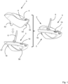
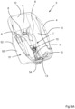
- Figure 1 shows a side view of a child seat transporting system 1 according to the invention comprising a safety part 2 and a child seat 3.
- the child seat 3 On the left side of figure 1 the child seat 3 is positioned above the safety part 2 just before connecting the child seat 3 to the safety part 2 as will be explained in more detail here below.
- the child seat 3 which can be used to transport a child by carrying it on two handles 4 of the child seat 3, which handles 4 extend in longitudinal direction of child seat 3.
- the handles 4 are retractable under spring force.
- the child seat 3 is inside the safety part 2 and is connected thereto to form an integrated unit 5.
- the unit 5 can be used to transport a child by carrying it on the U-shaped handle 6 of the safety part 2, which handle 6 is connected to two longitudinal sides of the safety part 2 or by carrying it on two handles 4 of the child seat 3.
- the unit 5 can be mounted on a seat of a vehicle and connected thereto by means of vehicle seat belts (not shown) to be guided through hooks 18, 19 mounted on the backside and near the front side of the safety part 2.
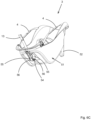
- Figures 2 and 3 are perspective views of the unit 5 comprising the safety part 2 and the child seat 3 connected thereto.
- the child seat 3 comprises a harness system 7 comprising two shoulder belts 8 and a crotch belt 9.
- the two shoulder belts 8 and the crotch belt 9 can be connected to each other by means of a lock 10.
- the shoulder belts 8 extend through holes 11 in a back portion 12 of the child seat 3.
- At the rear of the back portion 12 the shoulder belts 8 are connected to a single tensioner belt 13.
- the tensioner belt 13 extends through a tensioner 14 located near a front of the child seat 3.
- the connection of the crotch belt 9 to the child seat 3 is located on a seat portion 15 of the child seat 3 between the tensioner 14 and the back portion 12.
- Such harness system 7 is well known in the art and will therefore not further be explained.
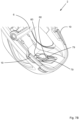
- Figure 3 shows the unit 5 from below.
- the safety part 2 comprises at a side remote of the handle 6, two pens 16, 17 extending parallel to each other and perpendicular to the longitudinal direction of the safety part 2.
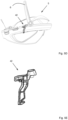
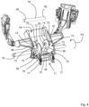
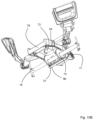
- Figure 4A shows the unit 5 comprising the safety part 2 and the child seat 3 connected thereto above a base 20 just before moving the unit 5 in a direction P0 towards the base 20 to connect it to the base 20.
- the base 20 is identical to the base as shown in EP2210768 of the same applicant as the present application.
- the base 20 comprises four hooks 21, 22 (only two are visible) each being rotatable with respect to the base 20 around an axis 23, 24.
- Two hooks 21 are located near the front side of the base 20 whilst two other hooks 22 are located near the rear side 25 of the base 20.
- the hooks 21, 22 are in a opened position, In a locked position an abutment surface 26 of each hook 21, 22 is located in a recess (not shown) of the base 20 whilst a gripping surface 27 on each hook 21, 22 are located outside the recess.
- Each hook 21, 22 is connected to a spring 28 forcing the hook 21, 22 to the opened position.
- the hooks 21, 22 are being moved by means of a slide 29 of the base 20 to the opened position wherein the pens 16, 17 can be respectively connected to the hooks 22, 21 by pushing the pens 16, 17 onto the abutment surface 26 of the respective hook 21, 22 due to which the hooks 21, 22 will pivot around axis 23, 24 against spring force of the springs 28 to the locked position.
- the pens 16, 17 will than be located in notches 30, 31 of the hooks 21, 22.
- the hooks 21, 22 will be locked by locking means.
- the exact working of the base 20 is described in detail in EP2210768 and will therefore not further be explained. Other well known means to connect the safety part 3 to the base 20 are also possible.
- the base 20 is also provided with hooks 33 near the rear side 25 thereof to connect the base 20 to ISOFIX-connectors 34 mounted in a vehicle.
- the base 20 is also provided with a leg 35 resting with an end remote of the base 20 on a floor of a vehicle. Such a leg 35 is well known and will therefore not be further explained.
- Figure 4B shows the unit 5 as mounted on the base 20 to form a child seat transporting system 1 to be used in a vehicle.
- Figure 4C shows that the child seat 3 has been removed from the safety part 2 after disconnecting the connection between them as will be explained here below.
- the handle 6 is first pivoted in a direction as indicated by arrow P1 about pivot axis 36 towards the rear side 25 of the base 20 to provide more space for the removal of the child seat 3.
- the use of only the child seat 3 to transport a child located therein and being hold by means of the harness has the advantage that a user only needs to carry the relatively light weighted child seat 3 and the child, whereas the heavier, more sturdy safety part 2 can remain on the base 20 inside the vehicle.
- the child seat 3 has a width W2 being smaller than the width W1 of the safety part 2.
- the width W1 is 440 millimetre
- W2 is 272 millimetre.
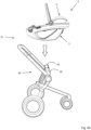
- Figure 5A shows the unit 5 comprising the safety part 2 and the child seat 3 connected thereto above a frame 40 of a stroller 41 just before connecting the unit 5 to the frame 40.
- the frame 40 of the stroller 41 is identical to the frame as shown in EP2108566B1 of the same applicant as the present application.
- the safety part 2 is provided on both longitudinal sides with first connecting elements 42 (see figures 5D and 5E ) whilst the frame 40 of the stroller 41 is provided with two second connecting elements 43.
- the first connecting elements 42 of the safety part 2 can be detachably connected to the second connecting elements 43 of the frame 40 of the stroller 41.
- the exact working of the connecting elements 42, 43 is described in detail in EP2108566B1 and will therefore not further be explained.
- the stroller 41 is preferably foldable and also comprises in a well known manner wheels 44 and a push bar 45. Other well known means to connect the safety part 3 to the frame 40 of the stroller 41 are also possible.
- Figure 5B shows the unit 5 as mounted on the frame 40 of the stroller 41 to form a child seat transporting system 1.
- Figure 5C shows that the child seat 3 has been removed from the safety part 2 after disconnecting the connection between them and moving the unit 5 in a direction P4 away from the safety part 2 mounted on the stroller 41 as will be explained here below.
- the handle 6 is first pivoted in a direction as indicated by arrow P1 about pivot axis 36 to provide more space for the removal of the child seat 3.
- the use of only the child seat 3 to transport a child located therein and being hold by means of the harness has the advantage that a user only needs to carry the relatively light weighted child seat 3 and the child, whereas the heavier and more sturdy safety part 2 can remain on the frame 40 of the stroller 41.
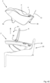
- FIGS 6A-6C show different views of the child seat 3.
- the child seat 3 comprises a shell 51 made of plastic such as polypropylene (PP).
- PP polypropylene
- the same material can be used for the safety part 2.
- the wall thickness of the child seat 3 will be less than the wall thickness of the safety part 3.
- the child seat 3 comprises two protrusions 52.
- the protrusions 52 can be inserted into blind holes 53 of the safety part 2 to position the child seat 3 in the safety part 2 and to prevent the child seat 3 to be able to tilt with respect to the safety part 2.
- the child seat 3 can rest with the protrusions 52 on a flat surface when used without the safety part 2.
- the child seat 3 At a side below the seat portion 15 the child seat 3 comprises a pen 54 extending perpendicular to the longitudinal direction of the child seat 3 and perpendicular to side walls 61 of the shell 51. An end of the crotch belt 9 remote of the lock 10 is connected to the pen 54.
- the pen 54 is supported by and extends through two flanges 55 forming an integral part of the shell 51. Each end 56 of the pen 54 forms a first pen of the coupling mechanism according to the present invention.
- FIGS 7A and 7B show different views of the safety part 2.
- the safety part 2 is made from a rigid plastic such as polypropylene (PP).
- PP polypropylene
- the weight of the child seat 3 is about 2 kilogram, the weight of the safety part 2 is about 3,4 kilogram, so the weight of the unit 5 is about 5,4 kilogram.
- Both the child seat 3 and the safety part 2 are preferably covered with a textile.
- the safety part 2 comprises a ring shaped frame 57 extending around the upper side of the safety part 2.
- the ring shaped frame 57 prevents the safety part 2 and therefor the child seat 3 when located inside the safety part 2 to be deformed in case of a crash like a car incident.
- the safety part 2 is provided with two enlarged passages 58 to reduce the weight of the safety part 2.
- the unit 5 comprising the safety part 2 and the child seat 3 fulfills the requirements regarding safety.
- the safety part 2 comprises a bottom part 59 to support the child seat 3.
- the blind holes 53 are located on both sides of the bottom part 59.
- the safety part 2 is near a front side thereof provided with two recesses 60 through which the pen 54 of the child seat 3 can be connected to two first hooks of the coupling mechanism according to the present invention, as will be explained here below.
- Figures 8-11 show a first embodiment of the coupling mechanism 71 according to the present invention.
- the coupling mechanism 71 comprises two coupling elements 72 each provided with the first hook 73 and a second hook 74.
- the coupling elements 72 are pivotable about pivot axes 75.
- Part of the coupling mechanism 71 is also pen 54 of the child seat 3 as well as pen 16 of the safety part 2 by means of which the safety part 2 can be connected to the base 20.
- the pen 54 cooperates with first hooks 73 whilst the pen 16 cooperates with second hooks 74.
- pen 16 and axes 75 extend parallel to each other.
- Each coupling element 72 is also provided with a third hook 76.
- the third hook 76 is attached to a spring 77.
- the spring 77 is attached at an end remote of the third hook 76 to an operating device 78.
- the coupling elements 72 are in a first position wherein the pen 54 of the child seat 2 is disconnected from the first hooks 73 and the child seat 3 and safety part 2 can be decoupled from each other. In the first position pen 16 of the safety part 2 is also is disconnected from the second hooks 74.
- Each coupling elements 72 comprises an abutment surface 79.
- Each first hook 73 comprises a notch 80 and a gripping surface 81.
- Each second hook 74 comprises a notch 82 and a gripping surface 83. In the first position the abutment surfaces 79 are located in the recesses 60 whilst the notches 80 and the gripping surfaces 81 on the first hook 73 are located outside the recesses 60.
- Each coupling elements 72 also comprises a locking surface 84.
- the protrusions 52 of the child seat 3 are inserted into the blind holes 53 of the safety part 2 and the pen 54 of the child seat 3 is brought into the recesses 60 and is pressed with a pressing force against the abutment surfaces 79 of the coupling elements 72. Due to this pressing force, the coupling elements 72 are being pivoted about the pivot axes 75 against spring force of the springs 77 in a direction indicated by arrow P2 to a second position.
- the pen 54 of the child seat 3 is located in the notches 80 of the first hooks 73 and engaged to the safety part 2 by means of the first hooks 73 and the gripping surfaces 81 thereof, whilst the pen 16 of the safety part 2 is located in the notches 82 of the second hooks 74.
- the pen 54 of the child seat 3 is directly coupled via the coupling elements 72 to the pen 16 of the safety part 2.
- the safety part 2 is coupled by means of the pen 16 to the base 20
- the child seat 3 is directly coupled via the coupling elements 72 to the pen 16 of the safety part 2 and to the base 20.
- the pens 56, 16 and the coupling elements 72 are made of a strong material like metal so that relatively large forces can easily and efficient be transmitted from the pen 54 to the pen 16 and to the base 20.
- the crotch belt 9 is connected to the pen 54.
- the locking surfaces 84 of the coupling elements 72 are brought in contact with locking surface 85 on the operating device 78 to lock the coupling elements 72 and the hooks 73, 74 thereof in said second position.
- the operating device 78 is being pivoted about pivot axis 86 against spring force of springs 77 in a direction as indicated by arrow P3, whereby under spring force of the springs 77 the coupling elements 72 are being pivoted in a direction opposite to arrow P2.
- abutment surfaces 79 of the coupling elements 72 pushes the pen 54 slightly out of the notches 80, whereafter still under spring force of the springs 77 the coupling elements 72 pivot to the first position.
- an angle A between a first virtual line 90 between the first pen 54 of the child seat 3 and the pivot axis 75 and a second virtual line 91 between the second pen 16 of the safety part 2 and the pivot axis 75 is for example 102 degrees degrees.
- An angle B between the first virtual line 90 horizontal H is for example between 48 and 63 degrees, so for example 55 degrees.
- the angle B is less than 90 degrees, preferably less than 63 degrees and more preferably less than 55 degrees, the movement of pen 54 in vertical direction along the vertical V towards and against the abutment surfaces 79 will cause pivoting of the coupling elements 72 in the direction indicated by arrow P2.
- the angle A as well as the distance between the first pen 54 of the child seat 3 and the pivot axis 75 determines the force needed to pivot the coupling elements 72.
- the pivoting is independent of the location and distance of the pen 16 with respect to the pivot axis 75.
- the pen 54 is located almost exactly vertical above the pen 16. Due to the coupling elements 72 comprising the first and second hooks 73, 74a freedom to determine the locations of the pens 54, 16 and axis 75 is obtained, whilst still a direct transmission of the forces from the pen 54 via coupling element 72 to pen 16 is obtained.
- Figures 12A and 12B show a second embodiment of a coupling element 92 of a coupling mechanism according to the invention.
- the coupling element 92 differs from the coupling element 72 in that it comprises a slotted hole 93 in which the pen 16 is located. A part of a wall 94 bounding the slotted hole 93 forms the second hook.
- Figure 13 is a perspective view of a person 101 carrying a unit 5 comprising a safety part 2 and a child seat 3 connected thereto with a hand 104.
- a child 102 is present in the child seat 3.
- the part 103 of the handle 6 extends perpendicular to the walking direction of the person.
- Safety part 2 and thus unit 5 has a width W1.
- Figure 14 is a perspective view of a person 101 carrying a child seat 3 by its handles 4 with a hand 104.
- the weight of the child seat 3 to be carried is less than the weight of the unit 5.
- the child seat 3 has in a direction perpendicular to the walking direction of the person a width W2 being smaller than the width W1 of unit 5 so that the child seat 3 can be held closer to the body of the person 101.
- This also makes it easier to carry the child seat 3.
- the difference can also easily be seen from the figures 16A and 16B showing respectively a rear view of a person carrying the unit 5 respectively a child seat 2.
- the orientation of the hand 104 is different. To carry the unit 5 the person must turn its wrist to be able to place its hand 104 on part 103 of the handle 6. To carry only the child seat 2 the person 101 can held its arm 105 almost flat along its body and does not need to turn its wrist.
- Figure 15 is a perspective view of a person carrying a child seat 2 by its arm 105. Due to the flexible handles 4 and the orientation thereof, the child seat 3 can also be easily carried close to its body on the persons arm 105.
- the child seat transporting system 1 has the advantage that the child can be transported in a number of different manners which can each time be chosen depending on the wishes of the person taking care of the child.
- the coupling mechanism to couple the safety part to the base, to couple the child seat directly to the base or to couple other components to each other.
- the child seat In case that the child seat will be directly coupled to the base, the child seat must fulfil the required safety regulations.
- the coupling mechanism comprises two coupling elements. However, it is also possible to use only one or more than two coupling elements.
- the safety part comprises ISOFIX-connectors so it can be directly connected to the vehicle seat without a vehicle belt.
Landscapes
- Engineering & Computer Science (AREA)
- Transportation (AREA)
- Mechanical Engineering (AREA)
- Health & Medical Sciences (AREA)
- Child & Adolescent Psychology (AREA)
- General Health & Medical Sciences (AREA)
- Aviation & Aerospace Engineering (AREA)
- Chemical & Material Sciences (AREA)
- Combustion & Propulsion (AREA)
- Seats For Vehicles (AREA)
Applications Claiming Priority (1)
| Application Number | Priority Date | Filing Date | Title |
|---|---|---|---|
| NL2023469A NL2023469B1 (en) | 2019-07-10 | 2019-07-10 | Child seat transporting system and safety part suitable for such a child seat transporting system |
Publications (2)
| Publication Number | Publication Date |
|---|---|
| EP3763564A1 EP3763564A1 (en) | 2021-01-13 |
| EP3763564B1 true EP3763564B1 (en) | 2025-02-26 |
Family
ID=67809616
Family Applications (1)
| Application Number | Title | Priority Date | Filing Date |
|---|---|---|---|
| EP20184899.1A Active EP3763564B1 (en) | 2019-07-10 | 2020-07-09 | Child seat transporting system and safety part suitable for such a child seat transporting system |
Country Status (6)
| Country | Link |
|---|---|
| US (1) | US11433787B2 (pl) |
| EP (1) | EP3763564B1 (pl) |
| CN (1) | CN214728333U (pl) |
| ES (1) | ES3018620T3 (pl) |
| NL (1) | NL2023469B1 (pl) |
| PL (1) | PL3763564T3 (pl) |
Families Citing this family (1)
| Publication number | Priority date | Publication date | Assignee | Title |
|---|---|---|---|---|
| GB2623504A (en) * | 2022-10-13 | 2024-04-24 | Icandy World Ltd | Car seats, bases and systems |
Citations (1)
| Publication number | Priority date | Publication date | Assignee | Title |
|---|---|---|---|---|
| US20060261105A1 (en) * | 2005-03-24 | 2006-11-23 | Cosco Management, Inc. | Juvenile seat with removable, wearable infant carrier sling |
Family Cites Families (50)
| Publication number | Priority date | Publication date | Assignee | Title |
|---|---|---|---|---|
| US3596986A (en) | 1970-03-30 | 1971-08-03 | Gen Motors Corp | Baby seat |
| WO1997007716A1 (en) | 1995-08-25 | 1997-03-06 | Ga International, Inc. | Child safety seat |
| US5806924A (en) | 1996-12-17 | 1998-09-15 | Cambridge Industries, Inc. | Baby seat |
| US6017088A (en) * | 1996-12-27 | 2000-01-25 | Evenflo Company, Inc. | Convertible infant carrier/restraint system |
| US6386632B1 (en) | 1997-10-14 | 2002-05-14 | Xsci, Inc. | Convertible child safety seat |
| US5893606A (en) * | 1997-12-12 | 1999-04-13 | Chiang; Mao-Chin | Multifunctional children gear |
| JP3656512B2 (ja) | 1999-05-10 | 2005-06-08 | タカタ株式会社 | チャイルドシート |
| US6517153B1 (en) * | 2000-03-03 | 2003-02-11 | Marvelee Brewer | All weather protective infant carrier cover/activity center |
| NO20003859L (no) | 2000-07-27 | 2002-01-28 | Torgersen Hans & Soenn | B¶reinnretning for barn |
| US6199949B1 (en) | 2000-07-31 | 2001-03-13 | Dasilva Eric S. | Child safety seat |
| GB2377677B (en) * | 2001-07-19 | 2004-09-29 | Andrew Bargery | Transporter |
| US6913313B2 (en) | 2002-03-04 | 2005-07-05 | Baby Trend, Inc. | Infant car seat handle and handle lock mechanism |
| US6715828B1 (en) | 2002-10-07 | 2004-04-06 | Kenny Cheng | Infant carrier |
| FI20040603A7 (fi) | 2004-04-28 | 2005-10-29 | Oy Klippan Ab | Lastenistuin |
| US7597396B2 (en) * | 2004-04-30 | 2009-10-06 | Chicco Usa, Inc. | Infant travel system |
| DE102004049919A1 (de) * | 2004-10-13 | 2006-04-20 | SCHÄFER, Friedrich | Babyschale zum Transport und zur Befestigung in einem Kraftfahrzeug |
| WO2006094341A1 (en) | 2005-03-08 | 2006-09-14 | Deirdre Maree Reeves | A portable infant support apparatus |
| GB2429401B (en) * | 2005-08-25 | 2009-06-24 | Abs Comtech Ltd | Child car seat |
| US20080067845A1 (en) | 2006-02-28 | 2008-03-20 | Britax Child Safety, Inc. | Carry handle seat latch for child safety seat |
| EP1969975A1 (en) | 2007-03-15 | 2008-09-17 | Team-Tex | Device for transporting a child |
| EP1970247A1 (en) | 2007-03-15 | 2008-09-17 | Team-Tex | Device for mounting a child seat in a car and a child seat |
| NL1035275C2 (nl) | 2008-04-09 | 2009-10-12 | Maxi Miliaan Bv | Samenstel omvattende een onderstel en een losneembaar met het onderstel koppelbare kinderzitting, een dergelijk onderstel alsmede een dergelijke kinderzitting. |
| NL1036453C2 (en) | 2009-01-23 | 2010-07-26 | Maxi Miliaan Bv | Child vehicle seat. |
| US8186757B2 (en) | 2009-03-04 | 2012-05-29 | Cosco Management, Inc. | Child restraint system including a stationary seat support and a removable juvenile vehicle seat on the seat support |
| US8210610B2 (en) * | 2009-03-16 | 2012-07-03 | Graco Children's Products Inc. | Reconfigurable child seat assembly for a juvenile product |
| US20100230933A1 (en) * | 2009-03-16 | 2010-09-16 | Graco Children's Products Inc. | Stroller Adapter for an Infant Car Seat |
| US8702169B2 (en) | 2010-06-04 | 2014-04-22 | Arvin Grande Abadilla | Method and apparatus for an infant safety seat |
| US8998312B2 (en) | 2010-10-29 | 2015-04-07 | Wonderland Nurserygoods Company Limited | Infant safety seat |
| DE202011000229U1 (de) | 2011-01-31 | 2011-06-09 | Curt Würstl Vermögensverwaltungs-GmbH & Co. KG, 95032 | Babyträger in Form eines Schalensitzes |
| CN202234240U (zh) | 2011-07-08 | 2012-05-30 | 克斯克管理公司 | 带把手的婴儿承载架 |
| US9751433B2 (en) | 2011-10-06 | 2017-09-05 | Thorley Industries Llc | Child restraint system with user interface |
| CN202843043U (zh) | 2012-09-07 | 2013-04-03 | 明门(中国)幼童用品有限公司 | 手把收折结构及具有该结构的儿童提篮 |
| US8911015B2 (en) * | 2013-03-05 | 2014-12-16 | Yochanan Cohen | Car seat |
| US10220734B2 (en) * | 2013-03-05 | 2019-03-05 | Pidyon Controls Inc. | Car seat |
| US8960794B2 (en) | 2013-04-02 | 2015-02-24 | John David St. Pierre | Child carrier and car seat combination |
| CN203713613U (zh) | 2013-08-15 | 2014-07-16 | 中山市隆成日用制品有限公司 | 幼儿汽车安全座椅锁定的安全显示设备 |
| US9119483B1 (en) * | 2014-03-14 | 2015-09-01 | Dorel Juvenile Group, Inc. | Child restraint system |
| US9487111B2 (en) * | 2014-03-24 | 2016-11-08 | Jason Lake | Spinning infant car seat |
| US9771006B2 (en) | 2014-05-16 | 2017-09-26 | Dorel Juvenile Group, Inc. | Child restraint |
| US9771007B2 (en) | 2015-01-29 | 2017-09-26 | Artsana USA, Inc | Multi-position rear-facing child seat |
| DE102015113852A1 (de) | 2015-08-20 | 2017-02-23 | Recaro Child Safety Gmbh & Co. Kg | Kindersitzsystem |
| CA2940813C (en) | 2015-09-03 | 2017-08-22 | Wonderland Nurserygoods Company Limited | Infant carrier |
| US10363842B2 (en) | 2015-09-11 | 2019-07-30 | Dorel Juvenile Group, Inc. | Vehicle anchor system for juvenile seat base |
| CN206383858U (zh) * | 2017-01-03 | 2017-08-08 | 明门瑞士股份有限公司 | 限制汽车椅背靠角度的底座及儿童汽车椅 |
| US11267376B2 (en) * | 2017-05-17 | 2022-03-08 | Illa Designs, LLC | Car seat carrier |
| US10028592B1 (en) * | 2017-11-03 | 2018-07-24 | Delia P. Ruiz | Carrier with a multi-purpose handle assembly |
| US11134793B2 (en) * | 2019-02-20 | 2021-10-05 | Dorel Juvenile Group, Inc. | Side carry handles for child carrier |
| US11034266B2 (en) * | 2019-02-27 | 2021-06-15 | Dorel Juvenile Group, Inc. | Child restraint |
| US10894492B2 (en) | 2019-03-26 | 2021-01-19 | Toyota Motor Engineering & Manufacturing North America, Inc | Vehicle seats providing access to child seat release latches |
| US11623549B2 (en) * | 2019-07-25 | 2023-04-11 | Dorel Juvenile Group, Inc. | Infant carrier |
-
2019
- 2019-07-10 NL NL2023469A patent/NL2023469B1/en active
-
2020
- 2020-07-07 US US16/922,302 patent/US11433787B2/en active Active
- 2020-07-09 PL PL20184899.1T patent/PL3763564T3/pl unknown
- 2020-07-09 ES ES20184899T patent/ES3018620T3/es active Active
- 2020-07-09 EP EP20184899.1A patent/EP3763564B1/en active Active
- 2020-07-10 CN CN202021358603.6U patent/CN214728333U/zh active Active
Patent Citations (1)
| Publication number | Priority date | Publication date | Assignee | Title |
|---|---|---|---|---|
| US20060261105A1 (en) * | 2005-03-24 | 2006-11-23 | Cosco Management, Inc. | Juvenile seat with removable, wearable infant carrier sling |
Also Published As
| Publication number | Publication date |
|---|---|
| ES3018620T3 (es) | 2025-05-16 |
| PL3763564T3 (pl) | 2025-06-09 |
| CN214728333U (zh) | 2021-11-16 |
| EP3763564A1 (en) | 2021-01-13 |
| US11433787B2 (en) | 2022-09-06 |
| US20210009011A1 (en) | 2021-01-14 |
| NL2023469B1 (en) | 2021-02-02 |
Similar Documents
| Publication | Publication Date | Title |
|---|---|---|
| EP3763565B1 (en) | A child seat transporting system | |
| US7017921B2 (en) | Stroller with retaining mechanism | |
| US6367875B1 (en) | Stay in view car seat | |
| US6305514B1 (en) | Off-centered dual-purpose handle assembly for wheeled luggage | |
| EP1880908A2 (en) | Seat assembly with multiple independent seat belts | |
| US20180312188A1 (en) | Child Stroller Apparatus | |
| EP1826094A1 (en) | Stroller | |
| CN101954874A (zh) | 车用座椅装置 | |
| US12037039B2 (en) | Child stroller apparatus | |
| US10293843B2 (en) | Juvenile stroller | |
| EP4157693B1 (en) | Convertible child stroller system with auxiliary basket | |
| KR20260025431A (ko) | 운송수단 내에 장착해제 가능하게 부착된 기저부 상에 또는 유모차 프레임 상에 탈착가능하게 장착되어야 할 캐리컷 | |
| EP3763564B1 (en) | Child seat transporting system and safety part suitable for such a child seat transporting system | |
| GB2392887A (en) | Baby carriage and baby's car seat mounted thereon | |
| JP2025506223A (ja) | キャリア | |
| CN120303149A (zh) | 儿童安全座椅 | |
| CN115384680B (zh) | 自行车拖车 | |
| US10967763B2 (en) | Removable and convertible seat assembly | |
| CN112203921A (zh) | 婴儿车 | |
| CN211107647U (zh) | 一种座椅可360度旋转的婴儿车 | |
| JP4266988B2 (ja) | 座席付き手押し車 | |
| CN223161831U (zh) | 手推车 | |
| JP2005162047A (ja) | かごが装着可能なベビーカー | |
| KR20260011129A (ko) | 리프트 아웃 캐리어가 구비된 시트 | |
| WO2024205490A9 (zh) | 动物运输推车 |
Legal Events
| Date | Code | Title | Description |
|---|---|---|---|
| PUAI | Public reference made under article 153(3) epc to a published international application that has entered the european phase |
Free format text: ORIGINAL CODE: 0009012 |
|
| STAA | Information on the status of an ep patent application or granted ep patent |
Free format text: STATUS: THE APPLICATION HAS BEEN PUBLISHED |
|
| AK | Designated contracting states |
Kind code of ref document: A1 Designated state(s): AL AT BE BG CH CY CZ DE DK EE ES FI FR GB GR HR HU IE IS IT LI LT LU LV MC MK MT NL NO PL PT RO RS SE SI SK SM TR |
|
| AX | Request for extension of the european patent |
Extension state: BA ME |
|
| STAA | Information on the status of an ep patent application or granted ep patent |
Free format text: STATUS: REQUEST FOR EXAMINATION WAS MADE |
|
| 17P | Request for examination filed |
Effective date: 20210713 |
|
| RBV | Designated contracting states (corrected) |
Designated state(s): AL AT BE BG CH CY CZ DE DK EE ES FI FR GB GR HR HU IE IS IT LI LT LU LV MC MK MT NL NO PL PT RO RS SE SI SK SM TR |
|
| STAA | Information on the status of an ep patent application or granted ep patent |
Free format text: STATUS: EXAMINATION IS IN PROGRESS |
|
| 17Q | First examination report despatched |
Effective date: 20211025 |
|
| 111Z | Information provided on other rights and legal means of execution |
Free format text: AL AT BE BG CH CY CZ DE DK EE ES FI FR GB GR HR HU IE IS IT LT LU LV MC MK MT NL NO PL PT RO RS SE SI SK SM TR Effective date: 20240110 |
|
| GRAP | Despatch of communication of intention to grant a patent |
Free format text: ORIGINAL CODE: EPIDOSNIGR1 |
|
| STAA | Information on the status of an ep patent application or granted ep patent |
Free format text: STATUS: GRANT OF PATENT IS INTENDED |
|
| INTG | Intention to grant announced |
Effective date: 20240507 |
|
| GRAJ | Information related to disapproval of communication of intention to grant by the applicant or resumption of examination proceedings by the epo deleted |
Free format text: ORIGINAL CODE: EPIDOSDIGR1 |
|
| STAA | Information on the status of an ep patent application or granted ep patent |
Free format text: STATUS: EXAMINATION IS IN PROGRESS |
|
| INTC | Intention to grant announced (deleted) | ||
| GRAS | Grant fee paid |
Free format text: ORIGINAL CODE: EPIDOSNIGR3 |
|
| STAA | Information on the status of an ep patent application or granted ep patent |
Free format text: STATUS: GRANT OF PATENT IS INTENDED |
|
| GRAP | Despatch of communication of intention to grant a patent |
Free format text: ORIGINAL CODE: EPIDOSNIGR1 |
|
| GRAA | (expected) grant |
Free format text: ORIGINAL CODE: 0009210 |
|
| STAA | Information on the status of an ep patent application or granted ep patent |
Free format text: STATUS: THE PATENT HAS BEEN GRANTED |
|
| P01 | Opt-out of the competence of the unified patent court (upc) registered |
Free format text: CASE NUMBER: APP_67461/2024 Effective date: 20241220 |
|
| INTG | Intention to grant announced |
Effective date: 20250110 |
|
| AK | Designated contracting states |
Kind code of ref document: B1 Designated state(s): AL AT BE BG CH CY CZ DE DK EE ES FI FR GB GR HR HU IE IS IT LI LT LU LV MC MK MT NL NO PL PT RO RS SE SI SK SM TR |
|
| REG | Reference to a national code |
Ref country code: GB Ref legal event code: FG4D |
|
| REG | Reference to a national code |
Ref country code: CH Ref legal event code: EP |
|
| REG | Reference to a national code |
Ref country code: NL Ref legal event code: FP |
|
| REG | Reference to a national code |
Ref country code: DE Ref legal event code: R096 Ref document number: 602020046654 Country of ref document: DE |
|
| REG | Reference to a national code |
Ref country code: IE Ref legal event code: FG4D |
|
| REG | Reference to a national code |
Ref country code: SE Ref legal event code: TRGR |
|
| REG | Reference to a national code |
Ref country code: ES Ref legal event code: FG2A Ref document number: 3018620 Country of ref document: ES Kind code of ref document: T3 Effective date: 20250516 |
|
| PG25 | Lapsed in a contracting state [announced via postgrant information from national office to epo] |
Ref country code: RS Free format text: LAPSE BECAUSE OF FAILURE TO SUBMIT A TRANSLATION OF THE DESCRIPTION OR TO PAY THE FEE WITHIN THE PRESCRIBED TIME-LIMIT Effective date: 20250526 |
|
| PG25 | Lapsed in a contracting state [announced via postgrant information from national office to epo] |
Ref country code: FI Free format text: LAPSE BECAUSE OF FAILURE TO SUBMIT A TRANSLATION OF THE DESCRIPTION OR TO PAY THE FEE WITHIN THE PRESCRIBED TIME-LIMIT Effective date: 20250226 |
|
| PGFP | Annual fee paid to national office [announced via postgrant information from national office to epo] |
Ref country code: PL Payment date: 20250630 Year of fee payment: 6 |
|
| REG | Reference to a national code |
Ref country code: LT Ref legal event code: MG9D |
|
| PG25 | Lapsed in a contracting state [announced via postgrant information from national office to epo] |
Ref country code: NO Free format text: LAPSE BECAUSE OF FAILURE TO SUBMIT A TRANSLATION OF THE DESCRIPTION OR TO PAY THE FEE WITHIN THE PRESCRIBED TIME-LIMIT Effective date: 20250526 Ref country code: IS Free format text: LAPSE BECAUSE OF FAILURE TO SUBMIT A TRANSLATION OF THE DESCRIPTION OR TO PAY THE FEE WITHIN THE PRESCRIBED TIME-LIMIT Effective date: 20250626 |
|
| PGFP | Annual fee paid to national office [announced via postgrant information from national office to epo] |
Ref country code: NL Payment date: 20250617 Year of fee payment: 6 |
|
| PG25 | Lapsed in a contracting state [announced via postgrant information from national office to epo] |
Ref country code: HR Free format text: LAPSE BECAUSE OF FAILURE TO SUBMIT A TRANSLATION OF THE DESCRIPTION OR TO PAY THE FEE WITHIN THE PRESCRIBED TIME-LIMIT Effective date: 20250226 |
|
| PG25 | Lapsed in a contracting state [announced via postgrant information from national office to epo] |
Ref country code: PT Free format text: LAPSE BECAUSE OF FAILURE TO SUBMIT A TRANSLATION OF THE DESCRIPTION OR TO PAY THE FEE WITHIN THE PRESCRIBED TIME-LIMIT Effective date: 20250626 Ref country code: LV Free format text: LAPSE BECAUSE OF FAILURE TO SUBMIT A TRANSLATION OF THE DESCRIPTION OR TO PAY THE FEE WITHIN THE PRESCRIBED TIME-LIMIT Effective date: 20250226 |
|
| PG25 | Lapsed in a contracting state [announced via postgrant information from national office to epo] |
Ref country code: BG Free format text: LAPSE BECAUSE OF FAILURE TO SUBMIT A TRANSLATION OF THE DESCRIPTION OR TO PAY THE FEE WITHIN THE PRESCRIBED TIME-LIMIT Effective date: 20250226 Ref country code: GR Free format text: LAPSE BECAUSE OF FAILURE TO SUBMIT A TRANSLATION OF THE DESCRIPTION OR TO PAY THE FEE WITHIN THE PRESCRIBED TIME-LIMIT Effective date: 20250527 |
|
| REG | Reference to a national code |
Ref country code: NL Ref legal event code: RC Free format text: DETAILS LICENCE OR PLEDGE: RIGHT OF PLEDGE, ESTABLISHED Name of requester: FEAC AGENT, LLC Effective date: 20250722 |
|
| REG | Reference to a national code |
Ref country code: AT Ref legal event code: MK05 Ref document number: 1770339 Country of ref document: AT Kind code of ref document: T Effective date: 20250226 |
|
| PG25 | Lapsed in a contracting state [announced via postgrant information from national office to epo] |
Ref country code: SM Free format text: LAPSE BECAUSE OF FAILURE TO SUBMIT A TRANSLATION OF THE DESCRIPTION OR TO PAY THE FEE WITHIN THE PRESCRIBED TIME-LIMIT Effective date: 20250226 |
|
| PGFP | Annual fee paid to national office [announced via postgrant information from national office to epo] |
Ref country code: ES Payment date: 20250827 Year of fee payment: 6 |
|
| PG25 | Lapsed in a contracting state [announced via postgrant information from national office to epo] |
Ref country code: DK Free format text: LAPSE BECAUSE OF FAILURE TO SUBMIT A TRANSLATION OF THE DESCRIPTION OR TO PAY THE FEE WITHIN THE PRESCRIBED TIME-LIMIT Effective date: 20250226 |
|
| PGFP | Annual fee paid to national office [announced via postgrant information from national office to epo] |
Ref country code: DE Payment date: 20250722 Year of fee payment: 6 |
|
| PGFP | Annual fee paid to national office [announced via postgrant information from national office to epo] |
Ref country code: IT Payment date: 20250724 Year of fee payment: 6 |
|
| PGFP | Annual fee paid to national office [announced via postgrant information from national office to epo] |
Ref country code: GB Payment date: 20250722 Year of fee payment: 6 |
|
| PG25 | Lapsed in a contracting state [announced via postgrant information from national office to epo] |
Ref country code: AT Free format text: LAPSE BECAUSE OF FAILURE TO SUBMIT A TRANSLATION OF THE DESCRIPTION OR TO PAY THE FEE WITHIN THE PRESCRIBED TIME-LIMIT Effective date: 20250226 |
|
| PGFP | Annual fee paid to national office [announced via postgrant information from national office to epo] |
Ref country code: FR Payment date: 20250725 Year of fee payment: 6 |
|
| PGFP | Annual fee paid to national office [announced via postgrant information from national office to epo] |
Ref country code: SE Payment date: 20250722 Year of fee payment: 6 |
|
| PG25 | Lapsed in a contracting state [announced via postgrant information from national office to epo] |
Ref country code: CZ Free format text: LAPSE BECAUSE OF FAILURE TO SUBMIT A TRANSLATION OF THE DESCRIPTION OR TO PAY THE FEE WITHIN THE PRESCRIBED TIME-LIMIT Effective date: 20250226 Ref country code: EE Free format text: LAPSE BECAUSE OF FAILURE TO SUBMIT A TRANSLATION OF THE DESCRIPTION OR TO PAY THE FEE WITHIN THE PRESCRIBED TIME-LIMIT Effective date: 20250226 |
|
| PG25 | Lapsed in a contracting state [announced via postgrant information from national office to epo] |
Ref country code: RO Free format text: LAPSE BECAUSE OF FAILURE TO SUBMIT A TRANSLATION OF THE DESCRIPTION OR TO PAY THE FEE WITHIN THE PRESCRIBED TIME-LIMIT Effective date: 20250226 |
|
| PG25 | Lapsed in a contracting state [announced via postgrant information from national office to epo] |
Ref country code: SK Free format text: LAPSE BECAUSE OF FAILURE TO SUBMIT A TRANSLATION OF THE DESCRIPTION OR TO PAY THE FEE WITHIN THE PRESCRIBED TIME-LIMIT Effective date: 20250226 |
|
| REG | Reference to a national code |
Ref country code: DE Ref legal event code: R097 Ref document number: 602020046654 Country of ref document: DE |
|
| REG | Reference to a national code |
Ref country code: NL Ref legal event code: RF Free format text: RIGHT OF PLEDGE, REMOVED Effective date: 20251111 |
|
| PLBE | No opposition filed within time limit |
Free format text: ORIGINAL CODE: 0009261 |
|
| STAA | Information on the status of an ep patent application or granted ep patent |
Free format text: STATUS: NO OPPOSITION FILED WITHIN TIME LIMIT |
|
| REG | Reference to a national code |
Ref country code: CH Ref legal event code: L10 Free format text: ST27 STATUS EVENT CODE: U-0-0-L10-L00 (AS PROVIDED BY THE NATIONAL OFFICE) Effective date: 20260107 |
|
| 26N | No opposition filed |
Effective date: 20251127 |
|
| REG | Reference to a national code |
Ref country code: CH Ref legal event code: H13 Free format text: ST27 STATUS EVENT CODE: U-0-0-H10-H13 (AS PROVIDED BY THE NATIONAL OFFICE) Effective date: 20260224 |
|
| PG25 | Lapsed in a contracting state [announced via postgrant information from national office to epo] |
Ref country code: LU Free format text: LAPSE BECAUSE OF NON-PAYMENT OF DUE FEES Effective date: 20250709 |
|
| REG | Reference to a national code |
Ref country code: BE Ref legal event code: MM Effective date: 20250731 |
|
| PG25 | Lapsed in a contracting state [announced via postgrant information from national office to epo] |
Ref country code: BE Free format text: LAPSE BECAUSE OF NON-PAYMENT OF DUE FEES Effective date: 20250731 |