EP3763619A1 - Élément structural de renforcement interne pour un fuselage et procédure de fabrication dudit élément structural - Google Patents
Élément structural de renforcement interne pour un fuselage et procédure de fabrication dudit élément structural Download PDFInfo
- Publication number
- EP3763619A1 EP3763619A1 EP19382591.6A EP19382591A EP3763619A1 EP 3763619 A1 EP3763619 A1 EP 3763619A1 EP 19382591 A EP19382591 A EP 19382591A EP 3763619 A1 EP3763619 A1 EP 3763619A1
- Authority
- EP
- European Patent Office
- Prior art keywords
- internal
- reinforcement element
- impregnated
- external
- fuselages
- Prior art date
- Legal status (The legal status is an assumption and is not a legal conclusion. Google has not performed a legal analysis and makes no representation as to the accuracy of the status listed.)
- Granted
Links
Images

Classifications
-
- B—PERFORMING OPERATIONS; TRANSPORTING
- B29—WORKING OF PLASTICS; WORKING OF SUBSTANCES IN A PLASTIC STATE IN GENERAL
- B29D—PRODUCING PARTICULAR ARTICLES FROM PLASTICS OR FROM SUBSTANCES IN A PLASTIC STATE
- B29D99/00—Subject matter not provided for in other groups of this subclass
- B29D99/001—Producing wall or panel-like structures, e.g. for hulls, fuselages, or buildings
- B29D99/0014—Producing wall or panel-like structures, e.g. for hulls, fuselages, or buildings provided with ridges or ribs, e.g. joined ribs
-
- B—PERFORMING OPERATIONS; TRANSPORTING
- B64—AIRCRAFT; AVIATION; COSMONAUTICS
- B64C—AEROPLANES; HELICOPTERS
- B64C1/00—Fuselages; Constructional features common to fuselages, wings, stabilising surfaces or the like
- B64C1/06—Frames; Stringers; Longerons ; Fuselage sections
- B64C1/061—Frames
-
- B—PERFORMING OPERATIONS; TRANSPORTING
- B64—AIRCRAFT; AVIATION; COSMONAUTICS
- B64F—GROUND OR AIRCRAFT-CARRIER-DECK INSTALLATIONS SPECIALLY ADAPTED FOR USE IN CONNECTION WITH AIRCRAFT; DESIGNING, MANUFACTURING, ASSEMBLING, CLEANING, MAINTAINING OR REPAIRING AIRCRAFT, NOT OTHERWISE PROVIDED FOR; HANDLING, TRANSPORTING, TESTING OR INSPECTING AIRCRAFT COMPONENTS, NOT OTHERWISE PROVIDED FOR
- B64F5/00—Designing, manufacturing, assembling, cleaning, maintaining or repairing aircraft, not otherwise provided for; Handling, transporting, testing or inspecting aircraft components, not otherwise provided for
- B64F5/10—Manufacturing or assembling aircraft, e.g. jigs therefor
-
- B—PERFORMING OPERATIONS; TRANSPORTING
- B64—AIRCRAFT; AVIATION; COSMONAUTICS
- B64C—AEROPLANES; HELICOPTERS
- B64C1/00—Fuselages; Constructional features common to fuselages, wings, stabilising surfaces or the like
- B64C2001/0054—Fuselage structures substantially made from particular materials
- B64C2001/0072—Fuselage structures substantially made from particular materials from composite materials
-
- Y—GENERAL TAGGING OF NEW TECHNOLOGICAL DEVELOPMENTS; GENERAL TAGGING OF CROSS-SECTIONAL TECHNOLOGIES SPANNING OVER SEVERAL SECTIONS OF THE IPC; TECHNICAL SUBJECTS COVERED BY FORMER USPC CROSS-REFERENCE ART COLLECTIONS [XRACs] AND DIGESTS
- Y02—TECHNOLOGIES OR APPLICATIONS FOR MITIGATION OR ADAPTATION AGAINST CLIMATE CHANGE
- Y02T—CLIMATE CHANGE MITIGATION TECHNOLOGIES RELATED TO TRANSPORTATION
- Y02T50/00—Aeronautics or air transport
- Y02T50/40—Weight reduction
Definitions
- the invention relates to the manufacture of a structural internal reinforcement element for fuselages, of a frame-like type, usable in the aeronautical, naval or railway sectors.
- the function of the fuselage is to withstand compression, traction, shear, flexion and torsion stresses with no failure of its skin.
- fuselage there are numerous types of fuselage which, throughout history, have enjoyed success in the field of transport; for example, the reinforced semi-monocoque fuselage is one of the most widely used, both in the aeronautical, naval and railway fields.
- This type of fuselage consists of a normally cylindrical structure formed by a skin and a number of reinforcement elements located on the internal side of said skin; that is, on the side of the skin opposite to the side which is in contact with the surrounding fluid.
- the reinforcement elements comprise frames, beams, stringers and ribs.
- Skin is the element of the fuselage structure that withstands the aerodynamic, rolling, static and dynamic loads. Its function is to endow the assembly with an aerodynamic shape, in addition to contributing to its structural strength.
- the longitudinal elements such as beams and stringers, are responsible for transmitting the loads acting upon the skin to the frames.
- the stringers withstand loads in a longitudinal direction, and endow the skin with rigidity, enabling a reduction in its thickness.
- transversal structural elements such as the ribs and frames, in combination with the skin itself, contribute to providing shape to the fuselage and transversal rigidity to the structure.
- Ribs and frames are transversal stiffening elements.
- their functions of particular note is their role in aiding the skin to withstand stresses and to maintain the cylindrical structure forming the fuselage.
- the object of the present invention is a structural element as an internal reinforcement for the manufacture of a fuselage, likewise the process for its manufacture.
- This structural element which may be a frame, that is, a transversal reinforcement element, is formed by two components: one which forms the principal part of the structural element and which will endow it with most of its final shape, manufactured from pre-impregnated composite material, for example SMC or BMC, reinforced by means of two reinforcement elements manufactured from fibre, which may be carbon fibre, impregnated with resin, which will be attached flush with both the interior and exterior of the previous element.
- pre-impregnated composite material for example SMC or BMC
- the object of the invention is therefore an internal structural reinforcement element for fuselages, featuring a longitudinal direction suited for its location in the longitudinal direction of the fuselage and a transversal direction perpendicular to its longitudinal direction, and is characterised in that it comprises:
- Another object of this invention is the procedure for the manufacture of the internal structural reinforcement element for fuselages, characterised in that it comprises the following steps:
- the above method of manufacture produces the bond between the component manufactured from pre-impregnated composite material and the two components manufactured from resin and fibre.
- This bond will form part of the manufacturing process, in such a way that the impregnated fibre and the component manufactured from pre-impregnated composite material become mutually embedded, and the joining of the two materials will be the manufacturing process in itself.
- the advantage of this manufacturing method lies in the achieving of a single component formed by two different types of material where no mechanical or adhesive joining is necessary. It is the pre-impregnated composite material itself which, during its shaping, adheres the internal and external reinforcements to itself.
- the manufacturing procedure is performed by the technique of overmoulding with reinforcements where first, fibre reinforcements are manufactured, for example by filament winding, which will be inserted into the mould for the subsequent manufacture by compression moulding of the frame with pre-impregnated composite material.
- both male moulds have an approximately tubular shape, with their longitudinal axis in accordance with the longitudinal direction of the fuselage.
- the structural reinforcement element corresponds to a frame.
- the first step in the manufacture of this frame corresponds to the manufacture of the fibre reinforcements.
- a filament winding technique will be employed whereby, commencing with a previously machined mandrel, which may be metallic, fibre thread is wound, for example carbon fibre, impregnated with resin, for example epoxy resin, which will be deposited, layer upon layer, on the mandrel.
- resin for example epoxy resin
- the mandrel will be removed, yielding, in said embodiment, a tube manufactured from carbon fibre in accordance with the characteristics desired. It will be necessary to perform the process twice, in order to manufacture two tubes, one internal and one external, which will form the internal and external reinforcements of the frame, respectively.
- the second step in the manufacture will be the compression moulding of pre-impregnated composite material.
- this will be performed by means of a reinforced overmoulding method.
- the second embodiment where the pre-impregnated material is not first introduced into the mould after positioning the reinforcements, but will be stored in a cavity located, for example, in the lower mould and will be forced in by a piston or similar subsequent to the closure of the mould with the reinforcements therein.
- a piston or similar subsequent to the closure of the mould with the reinforcements therein.
- the intermediate element might further comprise inserts, for example metallic inserts, in order to facilitate its joining with some other structural element of the craft.
- inserts for example metallic inserts
- the metal inserts would be perfectly inserted into the intermediate element, completely surrounded and grasped by the pre-impregnated material, that is, embedded.
- Said inserts may be of various geometric shapes, although it is important that their extremities be flat in order to maintain the flatness of the intermediate element.
- the final result will be a structural reinforcement element, for example a frame manufactured by means of pre-impregnated composite material reinforced, for example, by two rings of dry fibre impregnated with resin and located at the interior and exterior of the frame. Said rings are embedded in the frame in order to endow the assembly with rigidity and to create an internal structural reinforcement element, able to lend inertia to the section of fuselage and to facilitate the bonding with the remainder of the elements of said fuselage, in particular with the skin, contributing to the maintenance of the shape thereof.
- this frame will be performed in two stages, commencing with an adhesive bond, to be performed through the external reinforcement manufactured by means of the winding of a filament of dry fibre impregnated in a bath of resin, and subsequently by means of a mechanical join, such as riveting.
- a mechanical join such as riveting.
- Figure 5 portrays an embodiment of the invention which will act as a basis for the description of the reinforcement element which is the object of the invention, specifically portraying a frame (10) of the fuselage of a craft, consisting of an intermediate element (3) manufactured from pre-impregnated composite material, and two reinforcement elements (1, 2), made of carbon fibre, on both sides, in a direction transversal to that of the craft, manufactured in such a way that they become mutually embedded and form a single piece.
- the frame (10) therefore comprises:
- the frame (10) may also comprise one or several inserts (12), which may be metallic, located at any position within the intermediate element (3), as portrayed in figure 3 .
- the reinforcement elements (1, 2) are made of dry fibre impregnated in a bath of resin; more specifically, they may be made of resin-impregnated carbon fibre.
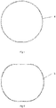
- Figure 1 portrays an embodiment of a first male mould (4) for the manufacture of the external reinforcement element (1).
- the fibre is in the form of a filament
- this first male mould (4) will act as a guide for a filament winding procedure by means of which the external reinforcement element (1), which will act as the external reinforcement of the frame (10), will be manufactured.
- figure 2 portrays the second male mould (5), which will act as a guide for the internal reinforcement element (2) of the frame (10).
- the stage of placing the resin-impregnated fibre on the first and second male moulds (4, 5) is performed by means of the winding of at least one filament of resin-impregnated fibre on the male mould (4, 5).
- the male moulds (4, 5) rotate at a suitable speed for the depositing of the fibre thereon.
- the quantity of fibre deposited may be varied, and thereby the rigidity of the external and internal reinforcements (1, 2).
- the resin-impregnated fibre is dry fibre impregnated in a bath of resin as a preliminary stage to its placement on the first and second male moulds (4, 5)
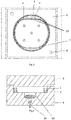
- the external and internal reinforcement tubes (1, 2) manufactured beforehand, are placed in a first part of a mould (6), resting against a number of tabs (7) to facilitate their placement and the subsequent extraction of the assembly.
- the space between both reinforcement elements (1, 2) is filled with pre-impregnated composite material which will later be formed by means of compression moulding.
- figure 3 portrays a plan view of the mould (6) wherein the reinforcement elements (1, 2) are located; these will be placed at the lower part of the mould (6), resting on the tabs (7) machined expressly to adapt the position of the same (1, 2).
- the pre-impregnated composite material, SMC or BMC will be placed in the space between both reinforcement elements (1, 2), filling the entire space designed to house the frame (10).
- the mould (6) will be closed, with the upper part of the same (6) adjusting the coupling by means of a number of centring elements (8).
- the pre-impregnated composite material SMC or BMC
- the pre-impregnated composite material is located in a cavity (13) in the lower mould (6), from where, after closure of the upper and lower mould (6), the pre-impregnated composite material will be forced into the space between the external and internal reinforcement elements (1, 2) by the action of a piston (14) or similar.
- a piston (14) or similar the correct position of the reinforcements (1, 2) is ensured prior to the addition of the pre-impregnated material which will fill the space in the mould (6) and will be formed around said reinforcements (1, 2).
- the upper part of the mould (6) will have a footprint with the shape of the frame (10), so that on closing the complete mould (6), the frame will be formed in accordance with its final shape. Both sections of the mould (6), previously heated, will be closed under specific conditions of temperature and pressure, during a set period of time, until the frame (10) is formed.
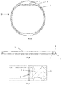
- Figure 6 portrays a longitudinal cross-sectional view of an embodiment of the frame (10), in such a way that the final aspect of the assembly may be seen, consisting of the intermediate element (3), manufactured from pre-impregnated composite material, and the two reinforcement elements (1, 2), of resin-impregnated fibre, located on both sides in a direction transversal to that of the frame (10), manufactured in such a way as to become mutually embedded and to form a single piece.
- Figure 7 portrays an enlargement of the cross-section of the frame (10), revealing the shape of the intermediate element (3), manufactured from pre-impregnated composite material, and that of the two reinforcement elements (1, 2), made of fibre.
- the external reinforcement (1) may be seen at the external part, and the internal reinforcement (2) may be observed in the interior.
- the external and internal reinforcement elements (1, 2) are located between the intermediate element (3), in the longitudinal direction of the structural element, as the intermediate element (3) features, in the longitudinal direction of the frame (10), an H-shaped cross-section, with a web in a longitudinal direction and the corresponding flanges in a direction transversal to the structural element, the external and internal reinforcement elements (1, 2) being embedded longitudinally in the frame (10), between the flanges of the intermediate element (3). In this way, the bond between the different elements of the frame (10) is improved.
- Figure 8 portrays the assembly of the frame (10) with the skin (9) and with the longitudinal and transversal reinforcement elements (11) of a fuselage.
- the bonding of the frame (10) to the skin (9) will be via the external reinforcement element (1) by means of mechanical bonding, such as adhesives and riveting.
Landscapes
- Engineering & Computer Science (AREA)
- Mechanical Engineering (AREA)
- Aviation & Aerospace Engineering (AREA)
- Manufacturing & Machinery (AREA)
- Architecture (AREA)
- Civil Engineering (AREA)
- Structural Engineering (AREA)
- Transportation (AREA)
- Moulding By Coating Moulds (AREA)
Priority Applications (4)
| Application Number | Priority Date | Filing Date | Title |
|---|---|---|---|
| ES19382591T ES2964631T3 (es) | 2019-07-12 | 2019-07-12 | Elemento estructural de refuerzo interno para fuselaje y procedimiento de fabricación de dicho elemento estructural |
| EP19382591.6A EP3763619B1 (fr) | 2019-07-12 | 2019-07-12 | Élément structural de renforcement interne pour un fuselage et procédure de fabrication dudit élément structural |
| PCT/ES2020/070444 WO2021009399A1 (fr) | 2019-07-12 | 2020-07-09 | Élément structurel de renforcement interne pour fuselage et procédé de fabrication de cet élément structurel |
| US17/626,735 US12006019B2 (en) | 2019-07-12 | 2020-07-09 | Structural internal reinforcement element for a fuselage, and procedure for the manufacture of said structural element |
Applications Claiming Priority (1)
| Application Number | Priority Date | Filing Date | Title |
|---|---|---|---|
| EP19382591.6A EP3763619B1 (fr) | 2019-07-12 | 2019-07-12 | Élément structural de renforcement interne pour un fuselage et procédure de fabrication dudit élément structural |
Publications (2)
| Publication Number | Publication Date |
|---|---|
| EP3763619A1 true EP3763619A1 (fr) | 2021-01-13 |
| EP3763619B1 EP3763619B1 (fr) | 2023-08-09 |
Family
ID=67658269
Family Applications (1)
| Application Number | Title | Priority Date | Filing Date |
|---|---|---|---|
| EP19382591.6A Active EP3763619B1 (fr) | 2019-07-12 | 2019-07-12 | Élément structural de renforcement interne pour un fuselage et procédure de fabrication dudit élément structural |
Country Status (4)
| Country | Link |
|---|---|
| US (1) | US12006019B2 (fr) |
| EP (1) | EP3763619B1 (fr) |
| ES (1) | ES2964631T3 (fr) |
| WO (1) | WO2021009399A1 (fr) |
Citations (5)
| Publication number | Priority date | Publication date | Assignee | Title |
|---|---|---|---|---|
| US4294639A (en) * | 1979-02-22 | 1981-10-13 | Motor Wheel Corporation | Fiber-reinforced composite wheel construction |
| US5024399A (en) * | 1988-06-08 | 1991-06-18 | Societe Nationale Industrielle Et Aetospatiale | Frame made of a composite material, especially for the fuselage of an aircraft, and its method of production |
| US5108810A (en) * | 1986-04-16 | 1992-04-28 | Courtaulds, Plc | Composite element |
| EP2469196A1 (fr) * | 2009-08-21 | 2012-06-27 | Mitsubishi Heavy Industries, Ltd. | Agencement de canalisation, équipement de canalisation, procédé de construction de renfort de canalisation, structure de renfort de support et structure de renfort pour unité de fixation de support |
| EP2532580A2 (fr) * | 2011-06-10 | 2012-12-12 | The Boeing Company | Composants structurels renforcés de fibres de bore |
Family Cites Families (3)
| Publication number | Priority date | Publication date | Assignee | Title |
|---|---|---|---|---|
| EP2284076A1 (fr) * | 2009-08-12 | 2011-02-16 | Dermond-Forstner & Sreboth OG | Procédé de fabrication d'un corps creux développé sous forme de structure en sandwich |
| US9463880B2 (en) * | 2013-02-07 | 2016-10-11 | The Boeing Company | Method and system of making composite structures having gap fillers with chopped fiber material |
| US11479333B2 (en) | 2016-12-16 | 2022-10-25 | Manuel Torres Martinez | Method for manufacturing a one-piece reinforced structure and obtained structure |
-
2019
- 2019-07-12 EP EP19382591.6A patent/EP3763619B1/fr active Active
- 2019-07-12 ES ES19382591T patent/ES2964631T3/es active Active
-
2020
- 2020-07-09 US US17/626,735 patent/US12006019B2/en active Active
- 2020-07-09 WO PCT/ES2020/070444 patent/WO2021009399A1/fr not_active Ceased
Patent Citations (5)
| Publication number | Priority date | Publication date | Assignee | Title |
|---|---|---|---|---|
| US4294639A (en) * | 1979-02-22 | 1981-10-13 | Motor Wheel Corporation | Fiber-reinforced composite wheel construction |
| US5108810A (en) * | 1986-04-16 | 1992-04-28 | Courtaulds, Plc | Composite element |
| US5024399A (en) * | 1988-06-08 | 1991-06-18 | Societe Nationale Industrielle Et Aetospatiale | Frame made of a composite material, especially for the fuselage of an aircraft, and its method of production |
| EP2469196A1 (fr) * | 2009-08-21 | 2012-06-27 | Mitsubishi Heavy Industries, Ltd. | Agencement de canalisation, équipement de canalisation, procédé de construction de renfort de canalisation, structure de renfort de support et structure de renfort pour unité de fixation de support |
| EP2532580A2 (fr) * | 2011-06-10 | 2012-12-12 | The Boeing Company | Composants structurels renforcés de fibres de bore |
Also Published As
| Publication number | Publication date |
|---|---|
| US12006019B2 (en) | 2024-06-11 |
| WO2021009399A1 (fr) | 2021-01-21 |
| US20220297816A1 (en) | 2022-09-22 |
| ES2964631T3 (es) | 2024-04-08 |
| EP3763619B1 (fr) | 2023-08-09 |
Similar Documents
| Publication | Publication Date | Title |
|---|---|---|
| CN102802925B (zh) | 复合连杆制造方法和根据该方法得到的连杆 | |
| US20210071707A1 (en) | Method for Producing a Positive-Locking Load Application for Rod-Shaped Fiber Composite Structures, and the Design Thereof | |
| US2929755A (en) | Plastic blades for gas turbine engines | |
| CN110315774B (zh) | 复合材料拉杆的成型方法及复合材料拉杆 | |
| US20030178738A1 (en) | Method for producing a fiber composite structural component | |
| AU2005313087B2 (en) | A trussed structure | |
| CN103889692A (zh) | 内部加强的管状复合支杆及其制造方法 | |
| US6319346B1 (en) | Method for manufacture of composite aircraft control surfaces | |
| GB2096530A (en) | A tubular hollow member and a method for its manufacture and a device for carrying out the method | |
| US9796142B2 (en) | Method for manufacturing a part made of composite material for an aircraft structure by pultrusion and cocuring | |
| EP3381665B1 (fr) | Composant structurel composite ayant un joint mécanique captif | |
| CN101171122B (zh) | 制造中空纤维增强结构件的方法 | |
| US12006019B2 (en) | Structural internal reinforcement element for a fuselage, and procedure for the manufacture of said structural element | |
| EP3127808B1 (fr) | Ensemble pale de rotor d'un giravion | |
| EP1595787A1 (fr) | Procédé de fabrication d'une gouverne à matériau composite pour un aéronef | |
| WO2017168131A1 (fr) | Raccord de nœud de structure à entretoises | |
| LU101087B1 (de) | Verfahren zum adaptiven Füllen von starren Werkzeugkavitäten | |
| JPH02155633A (ja) | 繊維強化プラスチック製トラス構造体の製造法 | |
| EP3115296A1 (fr) | Ensemble pale de rotor d'un giravion | |
| WO2022049558A1 (fr) | Procédé de fabrication d'un bras de suspension pour une suspension d'automobile et bras de suspension obtenu par ledit procédé | |
| EP4279254B1 (fr) | Arbre composite | |
| DE102014111176B4 (de) | Verfahren zur Herstellung eines Faserverbundbauteiles | |
| JP7533082B2 (ja) | 加圧治具、それを用いた繊維強化樹脂製パイプの製造方法及び製造装置 | |
| CN115750563A (zh) | 一种复合材料预埋连接件及其加工方法 | |
| CN121969844A (zh) | 复合材料支柱 |
Legal Events
| Date | Code | Title | Description |
|---|---|---|---|
| PUAI | Public reference made under article 153(3) epc to a published international application that has entered the european phase |
Free format text: ORIGINAL CODE: 0009012 |
|
| STAA | Information on the status of an ep patent application or granted ep patent |
Free format text: STATUS: THE APPLICATION HAS BEEN PUBLISHED |
|
| AK | Designated contracting states |
Kind code of ref document: A1 Designated state(s): AL AT BE BG CH CY CZ DE DK EE ES FI FR GB GR HR HU IE IS IT LI LT LU LV MC MK MT NL NO PL PT RO RS SE SI SK SM TR |
|
| AX | Request for extension of the european patent |
Extension state: BA ME |
|
| STAA | Information on the status of an ep patent application or granted ep patent |
Free format text: STATUS: REQUEST FOR EXAMINATION WAS MADE |
|
| 17P | Request for examination filed |
Effective date: 20210713 |
|
| RBV | Designated contracting states (corrected) |
Designated state(s): AL AT BE BG CH CY CZ DE DK EE ES FI FR GB GR HR HU IE IS IT LI LT LU LV MC MK MT NL NO PL PT RO RS SE SI SK SM TR |
|
| STAA | Information on the status of an ep patent application or granted ep patent |
Free format text: STATUS: EXAMINATION IS IN PROGRESS |
|
| 17Q | First examination report despatched |
Effective date: 20220131 |
|
| GRAP | Despatch of communication of intention to grant a patent |
Free format text: ORIGINAL CODE: EPIDOSNIGR1 |
|
| STAA | Information on the status of an ep patent application or granted ep patent |
Free format text: STATUS: GRANT OF PATENT IS INTENDED |
|
| RIC1 | Information provided on ipc code assigned before grant |
Ipc: B64C 1/00 20060101ALN20230320BHEP Ipc: B29C 70/86 20060101ALI20230320BHEP Ipc: B29C 70/34 20060101ALI20230320BHEP Ipc: B29D 99/00 20100101ALI20230320BHEP Ipc: B64C 1/06 20060101AFI20230320BHEP |
|
| INTG | Intention to grant announced |
Effective date: 20230417 |
|
| RIC1 | Information provided on ipc code assigned before grant |
Ipc: B64C 1/00 20060101ALN20230331BHEP Ipc: B29C 70/86 20060101ALI20230331BHEP Ipc: B29C 70/34 20060101ALI20230331BHEP Ipc: B29D 99/00 20100101ALI20230331BHEP Ipc: B64C 1/06 20060101AFI20230331BHEP |
|
| GRAS | Grant fee paid |
Free format text: ORIGINAL CODE: EPIDOSNIGR3 |
|
| GRAA | (expected) grant |
Free format text: ORIGINAL CODE: 0009210 |
|
| STAA | Information on the status of an ep patent application or granted ep patent |
Free format text: STATUS: THE PATENT HAS BEEN GRANTED |
|
| AK | Designated contracting states |
Kind code of ref document: B1 Designated state(s): AL AT BE BG CH CY CZ DE DK EE ES FI FR GB GR HR HU IE IS IT LI LT LU LV MC MK MT NL NO PL PT RO RS SE SI SK SM TR |
|
| REG | Reference to a national code |
Ref country code: GB Ref legal event code: FG4D |
|
| REG | Reference to a national code |
Ref country code: CH Ref legal event code: EP |
|
| REG | Reference to a national code |
Ref country code: IE Ref legal event code: FG4D |
|
| REG | Reference to a national code |
Ref country code: DE Ref legal event code: R096 Ref document number: 602019034503 Country of ref document: DE |
|
| REG | Reference to a national code |
Ref country code: LT Ref legal event code: MG9D |
|
| REG | Reference to a national code |
Ref country code: SE Ref legal event code: TRGR |
|
| REG | Reference to a national code |
Ref country code: NL Ref legal event code: MP Effective date: 20230809 |
|
| REG | Reference to a national code |
Ref country code: AT Ref legal event code: MK05 Ref document number: 1597250 Country of ref document: AT Kind code of ref document: T Effective date: 20230809 |
|
| PG25 | Lapsed in a contracting state [announced via postgrant information from national office to epo] |
Ref country code: GR Free format text: LAPSE BECAUSE OF FAILURE TO SUBMIT A TRANSLATION OF THE DESCRIPTION OR TO PAY THE FEE WITHIN THE PRESCRIBED TIME-LIMIT Effective date: 20231110 |
|
| PG25 | Lapsed in a contracting state [announced via postgrant information from national office to epo] |
Ref country code: IS Free format text: LAPSE BECAUSE OF FAILURE TO SUBMIT A TRANSLATION OF THE DESCRIPTION OR TO PAY THE FEE WITHIN THE PRESCRIBED TIME-LIMIT Effective date: 20231209 |
|
| PG25 | Lapsed in a contracting state [announced via postgrant information from national office to epo] |
Ref country code: RS Free format text: LAPSE BECAUSE OF FAILURE TO SUBMIT A TRANSLATION OF THE DESCRIPTION OR TO PAY THE FEE WITHIN THE PRESCRIBED TIME-LIMIT Effective date: 20230809 Ref country code: PT Free format text: LAPSE BECAUSE OF FAILURE TO SUBMIT A TRANSLATION OF THE DESCRIPTION OR TO PAY THE FEE WITHIN THE PRESCRIBED TIME-LIMIT Effective date: 20231211 Ref country code: NO Free format text: LAPSE BECAUSE OF FAILURE TO SUBMIT A TRANSLATION OF THE DESCRIPTION OR TO PAY THE FEE WITHIN THE PRESCRIBED TIME-LIMIT Effective date: 20231109 Ref country code: NL Free format text: LAPSE BECAUSE OF FAILURE TO SUBMIT A TRANSLATION OF THE DESCRIPTION OR TO PAY THE FEE WITHIN THE PRESCRIBED TIME-LIMIT Effective date: 20230809 Ref country code: LV Free format text: LAPSE BECAUSE OF FAILURE TO SUBMIT A TRANSLATION OF THE DESCRIPTION OR TO PAY THE FEE WITHIN THE PRESCRIBED TIME-LIMIT Effective date: 20230809 Ref country code: LT Free format text: LAPSE BECAUSE OF FAILURE TO SUBMIT A TRANSLATION OF THE DESCRIPTION OR TO PAY THE FEE WITHIN THE PRESCRIBED TIME-LIMIT Effective date: 20230809 Ref country code: IS Free format text: LAPSE BECAUSE OF FAILURE TO SUBMIT A TRANSLATION OF THE DESCRIPTION OR TO PAY THE FEE WITHIN THE PRESCRIBED TIME-LIMIT Effective date: 20231209 Ref country code: HR Free format text: LAPSE BECAUSE OF FAILURE TO SUBMIT A TRANSLATION OF THE DESCRIPTION OR TO PAY THE FEE WITHIN THE PRESCRIBED TIME-LIMIT Effective date: 20230809 Ref country code: GR Free format text: LAPSE BECAUSE OF FAILURE TO SUBMIT A TRANSLATION OF THE DESCRIPTION OR TO PAY THE FEE WITHIN THE PRESCRIBED TIME-LIMIT Effective date: 20231110 Ref country code: FI Free format text: LAPSE BECAUSE OF FAILURE TO SUBMIT A TRANSLATION OF THE DESCRIPTION OR TO PAY THE FEE WITHIN THE PRESCRIBED TIME-LIMIT Effective date: 20230809 Ref country code: AT Free format text: LAPSE BECAUSE OF FAILURE TO SUBMIT A TRANSLATION OF THE DESCRIPTION OR TO PAY THE FEE WITHIN THE PRESCRIBED TIME-LIMIT Effective date: 20230809 |
|
| PG25 | Lapsed in a contracting state [announced via postgrant information from national office to epo] |
Ref country code: PL Free format text: LAPSE BECAUSE OF FAILURE TO SUBMIT A TRANSLATION OF THE DESCRIPTION OR TO PAY THE FEE WITHIN THE PRESCRIBED TIME-LIMIT Effective date: 20230809 |
|
| REG | Reference to a national code |
Ref country code: ES Ref legal event code: FG2A Ref document number: 2964631 Country of ref document: ES Kind code of ref document: T3 Effective date: 20240408 |
|
| PG25 | Lapsed in a contracting state [announced via postgrant information from national office to epo] |
Ref country code: SM Free format text: LAPSE BECAUSE OF FAILURE TO SUBMIT A TRANSLATION OF THE DESCRIPTION OR TO PAY THE FEE WITHIN THE PRESCRIBED TIME-LIMIT Effective date: 20230809 Ref country code: RO Free format text: LAPSE BECAUSE OF FAILURE TO SUBMIT A TRANSLATION OF THE DESCRIPTION OR TO PAY THE FEE WITHIN THE PRESCRIBED TIME-LIMIT Effective date: 20230809 Ref country code: EE Free format text: LAPSE BECAUSE OF FAILURE TO SUBMIT A TRANSLATION OF THE DESCRIPTION OR TO PAY THE FEE WITHIN THE PRESCRIBED TIME-LIMIT Effective date: 20230809 Ref country code: DK Free format text: LAPSE BECAUSE OF FAILURE TO SUBMIT A TRANSLATION OF THE DESCRIPTION OR TO PAY THE FEE WITHIN THE PRESCRIBED TIME-LIMIT Effective date: 20230809 Ref country code: CZ Free format text: LAPSE BECAUSE OF FAILURE TO SUBMIT A TRANSLATION OF THE DESCRIPTION OR TO PAY THE FEE WITHIN THE PRESCRIBED TIME-LIMIT Effective date: 20230809 Ref country code: SK Free format text: LAPSE BECAUSE OF FAILURE TO SUBMIT A TRANSLATION OF THE DESCRIPTION OR TO PAY THE FEE WITHIN THE PRESCRIBED TIME-LIMIT Effective date: 20230809 |
|
| REG | Reference to a national code |
Ref country code: DE Ref legal event code: R097 Ref document number: 602019034503 Country of ref document: DE |
|
| PLBE | No opposition filed within time limit |
Free format text: ORIGINAL CODE: 0009261 |
|
| STAA | Information on the status of an ep patent application or granted ep patent |
Free format text: STATUS: NO OPPOSITION FILED WITHIN TIME LIMIT |
|
| 26N | No opposition filed |
Effective date: 20240513 |
|
| PG25 | Lapsed in a contracting state [announced via postgrant information from national office to epo] |
Ref country code: SI Free format text: LAPSE BECAUSE OF FAILURE TO SUBMIT A TRANSLATION OF THE DESCRIPTION OR TO PAY THE FEE WITHIN THE PRESCRIBED TIME-LIMIT Effective date: 20230809 |
|
| PG25 | Lapsed in a contracting state [announced via postgrant information from national office to epo] |
Ref country code: BG Free format text: LAPSE BECAUSE OF FAILURE TO SUBMIT A TRANSLATION OF THE DESCRIPTION OR TO PAY THE FEE WITHIN THE PRESCRIBED TIME-LIMIT Effective date: 20230809 |
|
| PG25 | Lapsed in a contracting state [announced via postgrant information from national office to epo] |
Ref country code: BG Free format text: LAPSE BECAUSE OF FAILURE TO SUBMIT A TRANSLATION OF THE DESCRIPTION OR TO PAY THE FEE WITHIN THE PRESCRIBED TIME-LIMIT Effective date: 20230809 |
|
| PG25 | Lapsed in a contracting state [announced via postgrant information from national office to epo] |
Ref country code: MC Free format text: LAPSE BECAUSE OF FAILURE TO SUBMIT A TRANSLATION OF THE DESCRIPTION OR TO PAY THE FEE WITHIN THE PRESCRIBED TIME-LIMIT Effective date: 20230809 |
|
| REG | Reference to a national code |
Ref country code: CH Ref legal event code: PL |
|
| PG25 | Lapsed in a contracting state [announced via postgrant information from national office to epo] |
Ref country code: LU Free format text: LAPSE BECAUSE OF NON-PAYMENT OF DUE FEES Effective date: 20240712 |
|
| GBPC | Gb: european patent ceased through non-payment of renewal fee |
Effective date: 20240712 |
|
| PG25 | Lapsed in a contracting state [announced via postgrant information from national office to epo] |
Ref country code: LU Free format text: LAPSE BECAUSE OF NON-PAYMENT OF DUE FEES Effective date: 20240712 |
|
| PG25 | Lapsed in a contracting state [announced via postgrant information from national office to epo] |
Ref country code: CH Free format text: LAPSE BECAUSE OF NON-PAYMENT OF DUE FEES Effective date: 20240731 Ref country code: BE Free format text: LAPSE BECAUSE OF NON-PAYMENT OF DUE FEES Effective date: 20240731 |
|
| PG25 | Lapsed in a contracting state [announced via postgrant information from national office to epo] |
Ref country code: GB Free format text: LAPSE BECAUSE OF NON-PAYMENT OF DUE FEES Effective date: 20240712 |
|
| REG | Reference to a national code |
Ref country code: BE Ref legal event code: MM Effective date: 20240731 |
|
| PG25 | Lapsed in a contracting state [announced via postgrant information from national office to epo] |
Ref country code: IE Free format text: LAPSE BECAUSE OF NON-PAYMENT OF DUE FEES Effective date: 20240712 |
|
| PGFP | Annual fee paid to national office [announced via postgrant information from national office to epo] |
Ref country code: ES Payment date: 20250811 Year of fee payment: 7 |
|
| PGFP | Annual fee paid to national office [announced via postgrant information from national office to epo] |
Ref country code: DE Payment date: 20250722 Year of fee payment: 7 |
|
| PGFP | Annual fee paid to national office [announced via postgrant information from national office to epo] |
Ref country code: TR Payment date: 20250707 Year of fee payment: 7 Ref country code: IT Payment date: 20250724 Year of fee payment: 7 |
|
| PGFP | Annual fee paid to national office [announced via postgrant information from national office to epo] |
Ref country code: FR Payment date: 20250725 Year of fee payment: 7 |
|
| PGFP | Annual fee paid to national office [announced via postgrant information from national office to epo] |
Ref country code: SE Payment date: 20250722 Year of fee payment: 7 |
|
| PG25 | Lapsed in a contracting state [announced via postgrant information from national office to epo] |
Ref country code: CY Free format text: LAPSE BECAUSE OF FAILURE TO SUBMIT A TRANSLATION OF THE DESCRIPTION OR TO PAY THE FEE WITHIN THE PRESCRIBED TIME-LIMIT; INVALID AB INITIO Effective date: 20190712 |
|
| PG25 | Lapsed in a contracting state [announced via postgrant information from national office to epo] |
Ref country code: HU Free format text: LAPSE BECAUSE OF FAILURE TO SUBMIT A TRANSLATION OF THE DESCRIPTION OR TO PAY THE FEE WITHIN THE PRESCRIBED TIME-LIMIT; INVALID AB INITIO Effective date: 20190712 |