EP3763621B1 - Hydraulisches betätigungssystem - Google Patents
Hydraulisches betätigungssystem Download PDFInfo
- Publication number
- EP3763621B1 EP3763621B1 EP19290055.3A EP19290055A EP3763621B1 EP 3763621 B1 EP3763621 B1 EP 3763621B1 EP 19290055 A EP19290055 A EP 19290055A EP 3763621 B1 EP3763621 B1 EP 3763621B1
- Authority
- EP
- European Patent Office
- Prior art keywords
- chamber
- actuator
- hydraulic
- actuation arrangement
- nacelle
- Prior art date
- Legal status (The legal status is an assumption and is not a legal conclusion. Google has not performed a legal analysis and makes no representation as to the accuracy of the status listed.)
- Active
Links
Images
Classifications
-
- B—PERFORMING OPERATIONS; TRANSPORTING
- B64—AIRCRAFT; AVIATION; COSMONAUTICS
- B64C—AEROPLANES; HELICOPTERS
- B64C11/00—Propellers, e.g. of ducted type; Features common to propellers and rotors for rotorcraft
- B64C11/30—Blade pitch-changing mechanisms
- B64C11/38—Blade pitch-changing mechanisms fluid, e.g. hydraulic
- B64C11/40—Blade pitch-changing mechanisms fluid, e.g. hydraulic automatic
-
- F—MECHANICAL ENGINEERING; LIGHTING; HEATING; WEAPONS; BLASTING
- F15—FLUID-PRESSURE ACTUATORS; HYDRAULICS OR PNEUMATICS IN GENERAL
- F15B—SYSTEMS ACTING BY MEANS OF FLUIDS IN GENERAL; FLUID-PRESSURE ACTUATORS, e.g. SERVOMOTORS; DETAILS OF FLUID-PRESSURE SYSTEMS, NOT OTHERWISE PROVIDED FOR
- F15B15/00—Fluid-actuated devices for displacing a member from one position to another; Gearing associated therewith
-
- F—MECHANICAL ENGINEERING; LIGHTING; HEATING; WEAPONS; BLASTING
- F15—FLUID-PRESSURE ACTUATORS; HYDRAULICS OR PNEUMATICS IN GENERAL
- F15B—SYSTEMS ACTING BY MEANS OF FLUIDS IN GENERAL; FLUID-PRESSURE ACTUATORS, e.g. SERVOMOTORS; DETAILS OF FLUID-PRESSURE SYSTEMS, NOT OTHERWISE PROVIDED FOR
- F15B20/00—Safety arrangements for fluid actuator systems; Applications of safety devices in fluid actuator systems; Emergency measures for fluid actuator systems
-
- F—MECHANICAL ENGINEERING; LIGHTING; HEATING; WEAPONS; BLASTING
- F15—FLUID-PRESSURE ACTUATORS; HYDRAULICS OR PNEUMATICS IN GENERAL
- F15B—SYSTEMS ACTING BY MEANS OF FLUIDS IN GENERAL; FLUID-PRESSURE ACTUATORS, e.g. SERVOMOTORS; DETAILS OF FLUID-PRESSURE SYSTEMS, NOT OTHERWISE PROVIDED FOR
- F15B2211/00—Circuits for servomotor systems
- F15B2211/20—Fluid pressure source, e.g. accumulator or variable axial piston pump
- F15B2211/205—Systems with pumps
- F15B2211/20507—Type of prime mover
- F15B2211/20515—Electric motor
-
- F—MECHANICAL ENGINEERING; LIGHTING; HEATING; WEAPONS; BLASTING
- F15—FLUID-PRESSURE ACTUATORS; HYDRAULICS OR PNEUMATICS IN GENERAL
- F15B—SYSTEMS ACTING BY MEANS OF FLUIDS IN GENERAL; FLUID-PRESSURE ACTUATORS, e.g. SERVOMOTORS; DETAILS OF FLUID-PRESSURE SYSTEMS, NOT OTHERWISE PROVIDED FOR
- F15B2211/00—Circuits for servomotor systems
- F15B2211/20—Fluid pressure source, e.g. accumulator or variable axial piston pump
- F15B2211/205—Systems with pumps
- F15B2211/20576—Systems with pumps with multiple pumps
-
- F—MECHANICAL ENGINEERING; LIGHTING; HEATING; WEAPONS; BLASTING
- F15—FLUID-PRESSURE ACTUATORS; HYDRAULICS OR PNEUMATICS IN GENERAL
- F15B—SYSTEMS ACTING BY MEANS OF FLUIDS IN GENERAL; FLUID-PRESSURE ACTUATORS, e.g. SERVOMOTORS; DETAILS OF FLUID-PRESSURE SYSTEMS, NOT OTHERWISE PROVIDED FOR
- F15B2211/00—Circuits for servomotor systems
- F15B2211/60—Circuit components or control therefor
- F15B2211/63—Electronic controllers
- F15B2211/6303—Electronic controllers using input signals
- F15B2211/6306—Electronic controllers using input signals representing a pressure
-
- F—MECHANICAL ENGINEERING; LIGHTING; HEATING; WEAPONS; BLASTING
- F15—FLUID-PRESSURE ACTUATORS; HYDRAULICS OR PNEUMATICS IN GENERAL
- F15B—SYSTEMS ACTING BY MEANS OF FLUIDS IN GENERAL; FLUID-PRESSURE ACTUATORS, e.g. SERVOMOTORS; DETAILS OF FLUID-PRESSURE SYSTEMS, NOT OTHERWISE PROVIDED FOR
- F15B2211/00—Circuits for servomotor systems
- F15B2211/70—Output members, e.g. hydraulic motors or cylinders or control therefor
- F15B2211/705—Output members, e.g. hydraulic motors or cylinders or control therefor characterised by the type of output members or actuators
- F15B2211/7051—Linear output members
- F15B2211/7053—Double-acting output members
-
- F—MECHANICAL ENGINEERING; LIGHTING; HEATING; WEAPONS; BLASTING
- F15—FLUID-PRESSURE ACTUATORS; HYDRAULICS OR PNEUMATICS IN GENERAL
- F15B—SYSTEMS ACTING BY MEANS OF FLUIDS IN GENERAL; FLUID-PRESSURE ACTUATORS, e.g. SERVOMOTORS; DETAILS OF FLUID-PRESSURE SYSTEMS, NOT OTHERWISE PROVIDED FOR
- F15B2211/00—Circuits for servomotor systems
- F15B2211/70—Output members, e.g. hydraulic motors or cylinders or control therefor
- F15B2211/705—Output members, e.g. hydraulic motors or cylinders or control therefor characterised by the type of output members or actuators
- F15B2211/7051—Linear output members
- F15B2211/7055—Linear output members having more than two chambers
-
- F—MECHANICAL ENGINEERING; LIGHTING; HEATING; WEAPONS; BLASTING
- F15—FLUID-PRESSURE ACTUATORS; HYDRAULICS OR PNEUMATICS IN GENERAL
- F15B—SYSTEMS ACTING BY MEANS OF FLUIDS IN GENERAL; FLUID-PRESSURE ACTUATORS, e.g. SERVOMOTORS; DETAILS OF FLUID-PRESSURE SYSTEMS, NOT OTHERWISE PROVIDED FOR
- F15B2211/00—Circuits for servomotor systems
- F15B2211/80—Other types of control related to particular problems or conditions
- F15B2211/857—Monitoring of fluid pressure systems
-
- F—MECHANICAL ENGINEERING; LIGHTING; HEATING; WEAPONS; BLASTING
- F15—FLUID-PRESSURE ACTUATORS; HYDRAULICS OR PNEUMATICS IN GENERAL
- F15B—SYSTEMS ACTING BY MEANS OF FLUIDS IN GENERAL; FLUID-PRESSURE ACTUATORS, e.g. SERVOMOTORS; DETAILS OF FLUID-PRESSURE SYSTEMS, NOT OTHERWISE PROVIDED FOR
- F15B2211/00—Circuits for servomotor systems
- F15B2211/80—Other types of control related to particular problems or conditions
- F15B2211/86—Control during or prevention of abnormal conditions
-
- F—MECHANICAL ENGINEERING; LIGHTING; HEATING; WEAPONS; BLASTING
- F15—FLUID-PRESSURE ACTUATORS; HYDRAULICS OR PNEUMATICS IN GENERAL
- F15B—SYSTEMS ACTING BY MEANS OF FLUIDS IN GENERAL; FLUID-PRESSURE ACTUATORS, e.g. SERVOMOTORS; DETAILS OF FLUID-PRESSURE SYSTEMS, NOT OTHERWISE PROVIDED FOR
- F15B2211/00—Circuits for servomotor systems
- F15B2211/80—Other types of control related to particular problems or conditions
- F15B2211/87—Detection of failures
-
- F—MECHANICAL ENGINEERING; LIGHTING; HEATING; WEAPONS; BLASTING
- F15—FLUID-PRESSURE ACTUATORS; HYDRAULICS OR PNEUMATICS IN GENERAL
- F15B—SYSTEMS ACTING BY MEANS OF FLUIDS IN GENERAL; FLUID-PRESSURE ACTUATORS, e.g. SERVOMOTORS; DETAILS OF FLUID-PRESSURE SYSTEMS, NOT OTHERWISE PROVIDED FOR
- F15B2211/00—Circuits for servomotor systems
- F15B2211/80—Other types of control related to particular problems or conditions
- F15B2211/875—Control measures for coping with failures
- F15B2211/8752—Emergency operation mode, e.g. fail-safe operation mode
-
- F—MECHANICAL ENGINEERING; LIGHTING; HEATING; WEAPONS; BLASTING
- F15—FLUID-PRESSURE ACTUATORS; HYDRAULICS OR PNEUMATICS IN GENERAL
- F15B—SYSTEMS ACTING BY MEANS OF FLUIDS IN GENERAL; FLUID-PRESSURE ACTUATORS, e.g. SERVOMOTORS; DETAILS OF FLUID-PRESSURE SYSTEMS, NOT OTHERWISE PROVIDED FOR
- F15B2211/00—Circuits for servomotor systems
- F15B2211/80—Other types of control related to particular problems or conditions
- F15B2211/875—Control measures for coping with failures
- F15B2211/8757—Control measures for coping with failures using redundant components or assemblies
Definitions
- This invention elates to a nacelle for an aircraft.
- this invention relates to nacelles with hydraulic systems for propellers, such as pitch change actuators.
- Hydraulic actuation systems that use hydraulic power to facilitate mechanical motion (e.g. linear, rotary or oscillatory motion) have many uses across a range of technologies.
- An hydraulic actuation system typically includes an hydraulic power supply, a metering valve (for example, an electro-hydraulic servovalve) controlled by a controller, and an actuator driven by the hydraulic flow from the metering valve.
- a typical linear hydraulic actuator includes a piston that can slide within a tube and can be single-acting or double-acting. In a double-acting actuator, hydraulic fluid pressure is applied from a chamber on each side of the piston and the pressure differential between the two chambers moves the piston one way or another.
- Propeller pitch control systems commonly use hydraulic actuation systems to control the pitch of the propeller blades, known as pitch change actuators.
- Variable pitch propellers are employed on many different types of vehicles, such as aircraft.
- propeller blades are mounted to a rotary hub for pivotable movement about their longitudinal axis to permit pitch adjustment.
- the pitch adjustment is controlled by an hydraulic pitch change actuator.
- the servo controller, hydraulic power supply and metering valve e.g. electro-hydraulic servovalve
- the static part of the nacelle e.g. the static part of the engine driving the propeller.
- a fault e.g. loss in pressure
- one of two methods is used to avoid catastrophic consequences of loss of control of the pitch of the propeller blades.
- One method and system is to provide pitch lock on the propeller blades to ensure that the blade pitch is locked at a setting slightly less than the pitch of the propeller at the time the oil pressure was lost.
- Another example of a system and method used when there is a fault is counterweights. Counterweights counteract the aerodynamic force that tries to move the blades toward a low-pitch angle. Both of these examples require cumbersome and heavy materials on the rotating part of the nacelle.
- EP2378081A2 relates to a back-up featherer for an engine arrangement and US9239064B2 relates to a fail-safe fluidic actuation system.
- EP2351925A2 also relates to a back-up featherer for an engine arrangement.
- the nacelle includes a rotating part with propeller blades and a static part.
- the nacelle includes a hydraulic actuation system.
- the hydraulic actuation system includes an actuator, a primary actuation arrangement to provide hydraulic fluid to control the actuator, wherein the hydraulic actuation system is configured to detect a fault in the actuator.
- the hydraulic actuation system also includes a secondary actuation arrangement to provide hydraulic fluid to control the actuator in response to a detection of a fault in the actuator.
- the actuator further includes a first chamber and a second chamber.
- the primary actuation arrangement is configured to control the hydraulic fluid in the first chamber and the second chamber.
- the actuator further includes a third chamber.
- the secondary actuation arrangement is configured to control the hydraulic fluid provided in the third chamber.
- the primary actuation arrangement is provided in or on the static part and the secondary actuation arrangement is provided in or on the rotating part.
- the secondary actuation arrangement further includes an electrically powered motor, a hydraulic pump and a secondary electro-hydraulic servo valve.
- the first chamber is configured to decrease pitch of a propeller blade of the aircraft.
- the second chamber is configured to increase pitch of the propeller blade of the aircraft.
- the third chamber is configured to increase pitch of the propeller blade of the aircraft.
- the primary actuation arrangement may include at least one pressure sensor to detect a fault in the actuator.
- the primary actuation arrangement may also include an electric pump, a main pump, a by-pass valve and a primary electro-hydraulic servovalve to control the actuator.
- the secondary actuation arrangement may include a signal module to provide a signal to a secondary electro-hydraulic servovalve to control the actuator.
- the actuator may further include at least one seal.
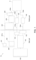
- Figure 1 shows an hydraulic actuation system 10 for a nacelle of the invention.
- the hydraulic actuation system 10 of Figure 1 includes a primary hydraulic actuation arrangement 100 (i.e., a primary hydraulic actuation system).
- the primary actuation arrangement 100 may include a maintenance pump 101 (e.g. an electrical pump), a main pump 102 (e.g. a mechanical pump), a by-pass valve 103 and an electro-hydraulic servovalve 104.
- the maintenance pump 101, main pump 102, by-pass valve 103 and a primary electro-hydraulic servovalve 104 of the primary actuation arrangement 100 may be provided on a static part (referred to in Figure 1 as 'static part') of the nacelle (not shown) to control the actuator A that is provided on the rotating part (referred to as 'rotating part' in Figure 1 ).
- the primary actuation arrangement 100 may also include pressure sensors 105 and 106 in the rotating part of the nacelle.
- the by-pass valve 103 may be connected by a transfer bearing 103a to the pressure sensor 105.
- the pressure sensor 105 may be connected to the actuator A by hydraulic line 103b.
- the primary electro-hydraulic servovalve 104 may be connected by a hydraulic line 104a to the pressure sensor 106.
- the pressure sensor 106 may be connected to the actuator A by hydraulic line 104b.
- the primary actuation arrangement 100 works to provide normal operation to the actuator A to provide pitch change to propellers. That is, the differential pressure provided by the by-pass valve 103 and the primary electro-hydraulic servovalve 104 act together to respond to pilot commands, or a controller of the aircraft, to alter the pitch of the propeller blades.
- the pressure sensors 105 and 106 monitor the pressure provided in the actuator A and provide input as to which hydraulic line needs to be altered to maintain or change the pitch of the propeller blades.
- the pressure sensors 105 and 106 can provide data to the pilot or a controller on the aircraft.
- the pressure sensors 105 and 106 are capable of detecting defaults on the hydraulic system by the controller or the pilot.
- FIG. 1 further shows a secondary actuation arrangement 200 (i.e., a secondary hydraulic actuation system).
- the secondary actuation arrangement 200 may include a signal module 201 that provides a signal 201a to a secondary electro-hydraulic servovalve 205.
- the secondary actuation arrangement 200 may also include a power module 202 to provide power to an electrically powered motor 203, which in turn may be connected to an hydraulic pump 204 that provides hydraulic fluid to the secondary electro-hydraulic servovalve 205.
- the secondary electro-hydraulic servovalve 205 may be connected by a hydraulic line 205a to actuator A.
- the electrically powered motor 203, the hydraulic pump 204 and the secondary electro-hydraulic servovalve 205 may be located in the rotating part of the nacelle.
- the primary actuation arrangement 100 provides normal operation to the actuator A. However, when a leak occurs in the actuator A, or there is a loss of pressure in the actuator A, the pressure sensors 105 and 106 detect a fault in the primary actuation arrangement 100. When a fault (e.g. loss of pressure) is detected in the primary actuation arrangement 100, the hydraulic actuation system 1 switches operation to the secondary actuator arrangement 200 that may be located on the rotating part of the nacelle. Therefore, the secondary actuator arrangement 200 acts as a back-up system on the nacelle to provide hydraulic function to the actuator A to resume manual or controller operations of the change in pitch of the propeller blades.
- a fault e.g. loss of pressure
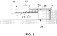
- FIG 2 shows the actuator A of Figure 1 .
- the actuator A includes a first chamber 300 (also known as a fine chamber) and a second chamber 301 (also known as a coarse chamber).
- the first chamber 300 and the second chamber 301 together act on the actuator A to provide pitch change in propeller blades.
- the pressure difference between the first chamber 300 and second chamber 301 allows for the pitch angle of the propeller blades to be altered by a pilot or a controller of an aircraft.
- the first chamber 300, or fine chamber may be set at a predetermined threshold value of pressure - for example a predetermined supply pressure ("P supply ").
- P supply predetermined supply pressure
- the second chamber 301, or coarse chamber may be altered from a pressure of between 0 and P supply.
- the first chamber 300 acts to decrease the pitch of the propeller blade
- the second chamber 301 acts to increase the pitch of the propeller blade
- the first chamber 300 may be connected to the by-pass valve 103 via transfer bearing 103a and hydraulic line 103b.
- the second chamber 301 may be connected to the primary electro-hydraulic servovalve 104
- the pressure sensors 105 and 106 of Figure 1 detect when there is a fault (e.g. loss of pressure) in the first chamber 300 and/or the second chamber 301.
- a fault e.g. loss of pressure
- the hydraulic actuation system 10 of Figure 1 switches from the primary actuation arrangement 100 to the secondary actuation arrangement 200 to resume operations of the actuator A to allow for the pitch in propeller blades to be maintained at a safe level.
- the primary actuation arrangement 100 fails, it may be the case that the external loads on the propeller blades are acting to decrease the pitch due to the centre of gravity and aerodynamic effects of the propeller blades.
- the secondary actuation arrangement 200 allows for a third chamber 306 to hydraulically control the actuator A and move the propeller blades to a high pitch to counteract the external load so that the blade pitch is always under control.
- the pressure provided by the third chamber 306 may be between 0 and P supply .
- the third chamber 306 may be connected to the secondary electro-hydraulic servovalve 205 that is provided in the rotating part.
- the actuator A may include at least one of a first, second, third, fourth and fifth dynamic seals 311, 312, 313, 314 and 315 to prevent leakage from the first chamber 300, second chamber 301 and third chamber 306. Although there are five seals shown in Figure 2 , it is envisaged that a greater number of seals may also be used to prevent leakage. There may also be provided a drain 316 between the first and second dynamic seals 311 and 312. In the example shown in Figure 2 , first seal 311 may prevent external leakage from the third chamber 306 to the drain 316. The second seal 312 prevents external leakage from the first chamber 300 to the drain 316. The third seal 313 prevents external leakage from the third chamber 306.
- the fourth seal 314 prevents leakage between the first chamber 300 and the second chamber 301.
- the fifth chamber 315 prevents external leakage from the second chamber 301.
- the drain 316 also acts to prevent leakages from the first chamber 300 and the third chamber 306. The drain 316 also prevents oils mixing within the actuator A.
Landscapes
- Engineering & Computer Science (AREA)
- Aviation & Aerospace Engineering (AREA)
- Physics & Mathematics (AREA)
- Fluid Mechanics (AREA)
- Mechanical Engineering (AREA)
- General Engineering & Computer Science (AREA)
- Chemical & Material Sciences (AREA)
- Analytical Chemistry (AREA)
- Fluid-Pressure Circuits (AREA)
Claims (11)
- Gondel für ein Luftfahrzeug, umfassend:ein rotierendes Teil mit Propellerschaufeln;ein statisches Teil;ein hydraulisches Betätigungssystem (10), wobei das hydraulische Betätigungssystem (10) umfasst:einen Aktuator (A);eine primäre Betätigungsanordnung (100), um Hydraulikfluid zum Steuern des Aktuators (A) bereitzustellen, wobei das hydraulische Betätigungssystem (10) so konfiguriert ist, dass es einen Fehler in dem Aktuator (A) erkennt;eine sekundäre Betätigungsanordnung (200), um Hydraulikfluid zum Steuern des Aktuators (A) in Reaktion auf ein Erkennen eines Fehlers in dem Aktuator (A) bereitzustellen;wobei der Aktuator (A) ferner umfasst:eine erste Kammer (300) und eine zweite Kammer (301), und wobei die primäre Betätigungsanordnung (100) das Hydraulikfluid in der ersten Kammer (300) und der zweiten Kammer (301) steuert; und eine dritte Kammer (306), wobei die sekundäre Betätigungsanordnung (100) das Hydraulikfluid steuert, das in der dritten Kammer (306) bereitgestellt wird;wobei die erste Kammer (300) dazu konfiguriert ist, die Steigung der Propellerschaufeln zu verringern;wobei die zweite Kammer (301) dazu konfiguriert ist, die Steigung der Propellerschaufeln zu erhöhen; undwobei die dritte Kammer (306) dazu konfiguriert ist, die Steigung der Propellerschaufeln zu erhöhen;wobei die primäre Betätigungsanordnung in oder an dem statischen Teil bereitgestellt ist und die sekundäre Betätigungsanordnung in oder an dem rotierenden Teil bereitgestellt ist;dadurch gekennzeichnet, dass die sekundäre Betätigungsanordnung umfasst:einen elektrisch angetriebenen Motor (203);eine Hydraulikpumpe (204); undein sekundäres elektrohydraulisches Servoventil (205).
- Gondel nach einem vorhergehenden Anspruch, wobei die primäre Betätigungsanordnung (100) mindestens einen Drucksensor (105, 106) beinhaltet, um einen Fehler in dem Aktuator (A) zu erkennen.
- Gondel nach einem vorhergehenden Anspruch, wobei die primäre Betätigungsanordnung (100) eine elektrische Pumpe (101), eine Hauptpumpe (102), ein Bypass-Ventil (103) und ein primäres elektrohydraulisches Servoventil (104) zum Steuern des Aktors (A) beinhaltet.
- Gondel nach einem vorhergehenden Anspruch, wobei die sekundäre Betätigungsanordnung (200) ein Signalmodul (201) beinhaltet, um ein Signal (201a) für das sekundäre elektrohydraulische Servoventil (205) bereitzustellen, um den Aktuator (A) zu steuern.
- Gondel nach einem vorhergehenden Anspruch, wobei der Aktuator (A) ferner mindestens eine Dichtung (311, 312, 313, 314, 315) umfasst.
- Gondel nach einem vorhergehenden Anspruch, wobei die primäre Betätigungsanordnung (100) an dem statischen Teil der Gondel bereitgestellt ist und die sekundäre Betätigungsanordnung an dem rotierenden Teil der Gondel bereitgestellt ist.
- Verfahren, umfassend:Bereitstellen einer Gondel für ein Luftfahrzeug, wobei die Gondel ein rotierendes Teil mit Propellerschaufeln und ein statisches Teil umfasst;Bereitstellen eines Aktuators (A);Bereitstellen von Hydraulikfluid zum Steuern des Aktuators (A) mit einer primären Betätigungsanordnung (100);Erkennen eines Fehlers in dem Aktuator (A) durch ein hydraulisches Betätigungssystem (10);Bereitstellen von Hydraulikflüssigkeit an den Aktuator (A) mit einer sekundären Betätigungsanordnung (200) als Reaktion auf den erkannten Fehler in dem Aktuator (A);wobei der Aktuator (A) ferner umfasst:eine erste Kammer (300) und eine zweite Kammer (301), und wobei die primäre Betätigungsanordnung (100) das Hydraulikfluid in der ersten Kammer (300) und der zweiten Kammer (301) steuert; und eine dritte Kammer (306), wobei die sekundäre Betätigungsanordnung (200) das Hydraulikfluid steuert, das in der dritten Kammer (306) bereitgestellt wird;wobei die erste Kammer (300) dazu konfiguriert ist, die Steigung der Propellerschaufeln zu verringern;wobei die zweite Kammer (301) dazu konfiguriert ist, die Steigung der Propellerschaufeln zu erhöhen; undwobei die dritte Kammer (306) dazu konfiguriert ist, die Steigung der Propellerschaufeln zu erhöhen;Bereitstellen der primären Betätigungsanordnung in oder an dem statischen Teil und Bereitstellen der sekundären Betätigungsanordnung in oder an dem rotierenden Teil;dadurch gekennzeichnet, dass die sekundäre Betätigungsanordnung umfasst:einen elektrisch angetriebenen Motor;eine Hydraulikpumpe; undein sekundäres elektrohydraulisches Servoventil.
- Verfahren nach Anspruch 7, wobei die primäre Betätigungsanordnung (100) eine elektrische Pumpe (101), eine Hauptpumpe (102), ein Bypass-Ventil (103) und ein primäres elektrohydraulisches Servoventil (104) zum Steuern des Aktors (A) beinhaltet.
- Verfahren nach einem der Ansprüche 7-8, wobei die sekundäre Betätigungsanordnung (200) ein Signalmodul (201) beinhaltet, um ein Signal (201a) für das sekundäre elektrohydraulische Servoventil (205) bereitzustellen, um den Aktuator (A) zu steuern.
- Verfahren nach einem der Ansprüche 7-9, wobei der Aktuator (A) ferner mindestens eine Dichtung (311, 312, 313, 314, 315) umfasst.
- Verfahren nach einem der Anspruch 7-10, wobei das Verfahren ferner umfasst:
Bereitstellen der primären Betätigungsanordnung (100) an dem statischen Teil der Gondel und Bereitstellen der sekundären Betätigungsanordnung (200) an dem rotierenden Teil der Gondel.
Priority Applications (6)
| Application Number | Priority Date | Filing Date | Title |
|---|---|---|---|
| EP19290055.3A EP3763621B1 (de) | 2019-07-12 | 2019-07-12 | Hydraulisches betätigungssystem |
| CA3063057A CA3063057A1 (en) | 2019-07-12 | 2019-11-26 | Hydraulic actuation system |
| BR102019026111-0A BR102019026111B1 (pt) | 2019-07-12 | 2019-12-10 | Sistema de atuação hidráulica e nacela para uma aeronave, e, método |
| RU2019140951A RU2019140951A (ru) | 2019-07-12 | 2019-12-11 | Гидравлическая приводная система |
| CN201911285938.1A CN112208745B (zh) | 2019-07-12 | 2019-12-13 | 液压致动系统 |
| US16/721,145 US11535363B2 (en) | 2019-07-12 | 2019-12-19 | Hydraulic actuation system |
Applications Claiming Priority (1)
| Application Number | Priority Date | Filing Date | Title |
|---|---|---|---|
| EP19290055.3A EP3763621B1 (de) | 2019-07-12 | 2019-07-12 | Hydraulisches betätigungssystem |
Publications (2)
| Publication Number | Publication Date |
|---|---|
| EP3763621A1 EP3763621A1 (de) | 2021-01-13 |
| EP3763621B1 true EP3763621B1 (de) | 2024-08-28 |
Family
ID=67614531
Family Applications (1)
| Application Number | Title | Priority Date | Filing Date |
|---|---|---|---|
| EP19290055.3A Active EP3763621B1 (de) | 2019-07-12 | 2019-07-12 | Hydraulisches betätigungssystem |
Country Status (5)
| Country | Link |
|---|---|
| US (1) | US11535363B2 (de) |
| EP (1) | EP3763621B1 (de) |
| CN (1) | CN112208745B (de) |
| CA (1) | CA3063057A1 (de) |
| RU (1) | RU2019140951A (de) |
Families Citing this family (2)
| Publication number | Priority date | Publication date | Assignee | Title |
|---|---|---|---|---|
| GB2586464B (en) * | 2019-08-18 | 2023-08-02 | Stats Uk Ltd | Pipeline isolation tool, assembly & method |
| EP4046907B1 (de) * | 2021-02-23 | 2024-10-09 | Ratier-Figeac SAS | Schaufelwinkelverstellungssteuerung |
Family Cites Families (18)
| Publication number | Priority date | Publication date | Assignee | Title |
|---|---|---|---|---|
| US5174718A (en) * | 1991-08-12 | 1992-12-29 | United Technologies Corporation | Blade pitch change control system |
| US6059528A (en) * | 1996-11-22 | 2000-05-09 | United Technologies Corporation | Electronic propeller control system |
| WO2003064803A2 (en) * | 2002-02-01 | 2003-08-07 | Smedvig Offshore As | A riser connector |
| US6796526B2 (en) * | 2002-11-25 | 2004-09-28 | The Boeing Company | Augmenting flight control surface actuation system and method |
| US7172391B2 (en) | 2004-08-03 | 2007-02-06 | Hamilton Sundstrand | Propeller actuation system |
| GB0821239D0 (en) * | 2008-11-21 | 2008-12-31 | Rolls Royce Plc | A machine such as a gas turbine |
| GB201000103D0 (en) * | 2010-01-06 | 2010-02-17 | Rolls Royce Plc | Back-Up Feathers |
| GB201000198D0 (en) * | 2010-01-08 | 2010-02-24 | Rolls Royce Plc | Back-up featherer |
| DE102010053811A1 (de) * | 2010-12-08 | 2012-06-14 | Moog Gmbh | Störungssicheres Betätigungssystem |
| DE102012012142A1 (de) * | 2012-06-20 | 2013-12-24 | Robert Bosch Gmbh | Hydraulische Stelleinrichtung |
| CN105339682B (zh) * | 2013-04-19 | 2017-06-13 | 派克汉尼芬公司 | 检测液压系统中的液压阀故障的方法 |
| FR3005632B1 (fr) | 2013-05-17 | 2015-05-29 | Eurocopter France | Distributeur hydraulique double d'une servocommande de manoeuvre des pales d'un rotor de giravion |
| US10106244B2 (en) * | 2014-11-07 | 2018-10-23 | The Boeing Company | Backup system |
| EP3219608B1 (de) * | 2016-03-18 | 2020-07-08 | Ratier-Figeac SAS | Verbesserte hydraulische betätigungssteuerung in propellern |
| US10683082B2 (en) | 2016-04-29 | 2020-06-16 | Ratier-Figeac Sas | Hydraulic actuation systems |
| EP3401553B1 (de) * | 2017-05-11 | 2020-12-23 | Ratier-Figeac SAS | Hydraulisches betätigungssystem |
| EP3431390B1 (de) * | 2017-07-17 | 2022-08-31 | Ratier-Figeac SAS | Hydraulischer aktuator |
| US10577080B2 (en) | 2017-08-23 | 2020-03-03 | Hamilton Sundstrand Corporation | Dual valve systems for actuator control |
-
2019
- 2019-07-12 EP EP19290055.3A patent/EP3763621B1/de active Active
- 2019-11-26 CA CA3063057A patent/CA3063057A1/en active Pending
- 2019-12-11 RU RU2019140951A patent/RU2019140951A/ru unknown
- 2019-12-13 CN CN201911285938.1A patent/CN112208745B/zh active Active
- 2019-12-19 US US16/721,145 patent/US11535363B2/en active Active
Also Published As
| Publication number | Publication date |
|---|---|
| CA3063057A1 (en) | 2021-01-12 |
| US11535363B2 (en) | 2022-12-27 |
| US20210009253A1 (en) | 2021-01-14 |
| RU2019140951A (ru) | 2021-06-11 |
| EP3763621A1 (de) | 2021-01-13 |
| CN112208745B (zh) | 2025-03-04 |
| BR102019026111A2 (pt) | 2021-01-26 |
| CN112208745A (zh) | 2021-01-12 |
Similar Documents
| Publication | Publication Date | Title |
|---|---|---|
| US5074495A (en) | Load-adaptive hybrid actuator system and method for actuating control surfaces | |
| RU2330997C2 (ru) | Гидравлическая система управления потоком для использования со сдвоенным гидроприводом, сервоприводная система управления и способ обеспечения резервированного управления потоком для гидропривода | |
| US8505848B2 (en) | Aircraft actuator hydraulic system | |
| US11827336B2 (en) | Propeller blade angle closed loop control by solenoid modulation | |
| EP2653381B1 (de) | Verbessertes propellerblattanstellsystem | |
| CN110304238B (zh) | 分布式后缘机翼襟翼系统 | |
| US6261062B1 (en) | Actuation system for a controllable pitch propeller | |
| US20210139134A1 (en) | Hydraulic cylinder with matching bias | |
| EP3763621B1 (de) | Hydraulisches betätigungssystem | |
| EP2631171A2 (de) | Hydraulisches Aktuatorsystem für Flugzeug | |
| US11313391B2 (en) | Actuator system for a fly-by-wire aircraft | |
| US4907992A (en) | Oil distribution box for a marine controllable pitch propeller | |
| EP3875784B1 (de) | System zur aufrechterhaltung der zuletzt befohlenen position einer durch ein zweistufiges elektrohydraulisches servoventil gesteuerten vorrichtung bei stromunterbrechung | |
| EP3431390B1 (de) | Hydraulischer aktuator | |
| US20120099991A1 (en) | Hydraulic Variable Pitch Propeller | |
| US20220266982A1 (en) | Blade pitch control | |
| US12392361B1 (en) | Cross-bleed safety mechanism for a linear hydraulic actuator | |
| US3924555A (en) | Stabilizing fin system | |
| EP4400420B1 (de) | Stoppsschutzverwaltung für einen ema mit droop-funktion | |
| RU2484314C2 (ru) | Двухрежимный электрогидравлический привод с нереверсивным насосом | |
| US4363211A (en) | Quasi-open loop hydraulic ram incremental actuator with power conserving properties | |
| US20120070291A1 (en) | Propeller and system of counter-rotating propellers comprising improved means for limiting pitch, and a turbine engine comprising them | |
| BR102019026111B1 (pt) | Sistema de atuação hidráulica e nacela para uma aeronave, e, método | |
| RU2483977C2 (ru) | Двухрежимный электрогидравлический привод с дополнительными режимами кольцевания и демпфирования выходного звена | |
| US12504029B2 (en) | Aerospace actuator stroke limiting device |
Legal Events
| Date | Code | Title | Description |
|---|---|---|---|
| PUAI | Public reference made under article 153(3) epc to a published international application that has entered the european phase |
Free format text: ORIGINAL CODE: 0009012 |
|
| STAA | Information on the status of an ep patent application or granted ep patent |
Free format text: STATUS: THE APPLICATION HAS BEEN PUBLISHED |
|
| AK | Designated contracting states |
Kind code of ref document: A1 Designated state(s): AL AT BE BG CH CY CZ DE DK EE ES FI FR GB GR HR HU IE IS IT LI LT LU LV MC MK MT NL NO PL PT RO RS SE SI SK SM TR |
|
| AX | Request for extension of the european patent |
Extension state: BA ME |
|
| STAA | Information on the status of an ep patent application or granted ep patent |
Free format text: STATUS: REQUEST FOR EXAMINATION WAS MADE |
|
| 17P | Request for examination filed |
Effective date: 20210713 |
|
| RBV | Designated contracting states (corrected) |
Designated state(s): AL AT BE BG CH CY CZ DE DK EE ES FI FR GB GR HR HU IE IS IT LI LT LU LV MC MK MT NL NO PL PT RO RS SE SI SK SM TR |
|
| STAA | Information on the status of an ep patent application or granted ep patent |
Free format text: STATUS: EXAMINATION IS IN PROGRESS |
|
| 17Q | First examination report despatched |
Effective date: 20230510 |
|
| GRAP | Despatch of communication of intention to grant a patent |
Free format text: ORIGINAL CODE: EPIDOSNIGR1 |
|
| STAA | Information on the status of an ep patent application or granted ep patent |
Free format text: STATUS: GRANT OF PATENT IS INTENDED |
|
| INTG | Intention to grant announced |
Effective date: 20240327 |
|
| GRAS | Grant fee paid |
Free format text: ORIGINAL CODE: EPIDOSNIGR3 |
|
| GRAA | (expected) grant |
Free format text: ORIGINAL CODE: 0009210 |
|
| STAA | Information on the status of an ep patent application or granted ep patent |
Free format text: STATUS: THE PATENT HAS BEEN GRANTED |
|
| AK | Designated contracting states |
Kind code of ref document: B1 Designated state(s): AL AT BE BG CH CY CZ DE DK EE ES FI FR GB GR HR HU IE IS IT LI LT LU LV MC MK MT NL NO PL PT RO RS SE SI SK SM TR |
|
| REG | Reference to a national code |
Ref country code: GB Ref legal event code: FG4D |
|
| REG | Reference to a national code |
Ref country code: CH Ref legal event code: EP |
|
| REG | Reference to a national code |
Ref country code: DE Ref legal event code: R096 Ref document number: 602019057806 Country of ref document: DE |
|
| REG | Reference to a national code |
Ref country code: IE Ref legal event code: FG4D |
|
| REG | Reference to a national code |
Ref country code: LT Ref legal event code: MG9D |
|
| PG25 | Lapsed in a contracting state [announced via postgrant information from national office to epo] |
Ref country code: NO Free format text: LAPSE BECAUSE OF FAILURE TO SUBMIT A TRANSLATION OF THE DESCRIPTION OR TO PAY THE FEE WITHIN THE PRESCRIBED TIME-LIMIT Effective date: 20241128 |
|
| REG | Reference to a national code |
Ref country code: AT Ref legal event code: MK05 Ref document number: 1717699 Country of ref document: AT Kind code of ref document: T Effective date: 20240828 |
|
| PG25 | Lapsed in a contracting state [announced via postgrant information from national office to epo] |
Ref country code: NL Free format text: LAPSE BECAUSE OF FAILURE TO SUBMIT A TRANSLATION OF THE DESCRIPTION OR TO PAY THE FEE WITHIN THE PRESCRIBED TIME-LIMIT Effective date: 20240828 Ref country code: PL Free format text: LAPSE BECAUSE OF FAILURE TO SUBMIT A TRANSLATION OF THE DESCRIPTION OR TO PAY THE FEE WITHIN THE PRESCRIBED TIME-LIMIT Effective date: 20240828 Ref country code: GR Free format text: LAPSE BECAUSE OF FAILURE TO SUBMIT A TRANSLATION OF THE DESCRIPTION OR TO PAY THE FEE WITHIN THE PRESCRIBED TIME-LIMIT Effective date: 20241129 Ref country code: PT Free format text: LAPSE BECAUSE OF FAILURE TO SUBMIT A TRANSLATION OF THE DESCRIPTION OR TO PAY THE FEE WITHIN THE PRESCRIBED TIME-LIMIT Effective date: 20241230 Ref country code: FI Free format text: LAPSE BECAUSE OF FAILURE TO SUBMIT A TRANSLATION OF THE DESCRIPTION OR TO PAY THE FEE WITHIN THE PRESCRIBED TIME-LIMIT Effective date: 20240828 |
|
| PG25 | Lapsed in a contracting state [announced via postgrant information from national office to epo] |
Ref country code: BG Free format text: LAPSE BECAUSE OF FAILURE TO SUBMIT A TRANSLATION OF THE DESCRIPTION OR TO PAY THE FEE WITHIN THE PRESCRIBED TIME-LIMIT Effective date: 20240828 |
|
| PG25 | Lapsed in a contracting state [announced via postgrant information from national office to epo] |
Ref country code: LV Free format text: LAPSE BECAUSE OF FAILURE TO SUBMIT A TRANSLATION OF THE DESCRIPTION OR TO PAY THE FEE WITHIN THE PRESCRIBED TIME-LIMIT Effective date: 20240828 |
|
| REG | Reference to a national code |
Ref country code: NL Ref legal event code: MP Effective date: 20240828 |
|
| PG25 | Lapsed in a contracting state [announced via postgrant information from national office to epo] |
Ref country code: AT Free format text: LAPSE BECAUSE OF FAILURE TO SUBMIT A TRANSLATION OF THE DESCRIPTION OR TO PAY THE FEE WITHIN THE PRESCRIBED TIME-LIMIT Effective date: 20240828 Ref country code: IS Free format text: LAPSE BECAUSE OF FAILURE TO SUBMIT A TRANSLATION OF THE DESCRIPTION OR TO PAY THE FEE WITHIN THE PRESCRIBED TIME-LIMIT Effective date: 20241228 |
|
| PG25 | Lapsed in a contracting state [announced via postgrant information from national office to epo] |
Ref country code: HR Free format text: LAPSE BECAUSE OF FAILURE TO SUBMIT A TRANSLATION OF THE DESCRIPTION OR TO PAY THE FEE WITHIN THE PRESCRIBED TIME-LIMIT Effective date: 20240828 |
|
| PG25 | Lapsed in a contracting state [announced via postgrant information from national office to epo] |
Ref country code: RS Free format text: LAPSE BECAUSE OF FAILURE TO SUBMIT A TRANSLATION OF THE DESCRIPTION OR TO PAY THE FEE WITHIN THE PRESCRIBED TIME-LIMIT Effective date: 20241128 Ref country code: ES Free format text: LAPSE BECAUSE OF FAILURE TO SUBMIT A TRANSLATION OF THE DESCRIPTION OR TO PAY THE FEE WITHIN THE PRESCRIBED TIME-LIMIT Effective date: 20240828 |
|
| PG25 | Lapsed in a contracting state [announced via postgrant information from national office to epo] |
Ref country code: RS Free format text: LAPSE BECAUSE OF FAILURE TO SUBMIT A TRANSLATION OF THE DESCRIPTION OR TO PAY THE FEE WITHIN THE PRESCRIBED TIME-LIMIT Effective date: 20241128 Ref country code: PT Free format text: LAPSE BECAUSE OF FAILURE TO SUBMIT A TRANSLATION OF THE DESCRIPTION OR TO PAY THE FEE WITHIN THE PRESCRIBED TIME-LIMIT Effective date: 20241230 Ref country code: PL Free format text: LAPSE BECAUSE OF FAILURE TO SUBMIT A TRANSLATION OF THE DESCRIPTION OR TO PAY THE FEE WITHIN THE PRESCRIBED TIME-LIMIT Effective date: 20240828 Ref country code: NO Free format text: LAPSE BECAUSE OF FAILURE TO SUBMIT A TRANSLATION OF THE DESCRIPTION OR TO PAY THE FEE WITHIN THE PRESCRIBED TIME-LIMIT Effective date: 20241128 Ref country code: NL Free format text: LAPSE BECAUSE OF FAILURE TO SUBMIT A TRANSLATION OF THE DESCRIPTION OR TO PAY THE FEE WITHIN THE PRESCRIBED TIME-LIMIT Effective date: 20240828 Ref country code: LV Free format text: LAPSE BECAUSE OF FAILURE TO SUBMIT A TRANSLATION OF THE DESCRIPTION OR TO PAY THE FEE WITHIN THE PRESCRIBED TIME-LIMIT Effective date: 20240828 Ref country code: IS Free format text: LAPSE BECAUSE OF FAILURE TO SUBMIT A TRANSLATION OF THE DESCRIPTION OR TO PAY THE FEE WITHIN THE PRESCRIBED TIME-LIMIT Effective date: 20241228 Ref country code: HR Free format text: LAPSE BECAUSE OF FAILURE TO SUBMIT A TRANSLATION OF THE DESCRIPTION OR TO PAY THE FEE WITHIN THE PRESCRIBED TIME-LIMIT Effective date: 20240828 Ref country code: GR Free format text: LAPSE BECAUSE OF FAILURE TO SUBMIT A TRANSLATION OF THE DESCRIPTION OR TO PAY THE FEE WITHIN THE PRESCRIBED TIME-LIMIT Effective date: 20241129 Ref country code: FI Free format text: LAPSE BECAUSE OF FAILURE TO SUBMIT A TRANSLATION OF THE DESCRIPTION OR TO PAY THE FEE WITHIN THE PRESCRIBED TIME-LIMIT Effective date: 20240828 Ref country code: ES Free format text: LAPSE BECAUSE OF FAILURE TO SUBMIT A TRANSLATION OF THE DESCRIPTION OR TO PAY THE FEE WITHIN THE PRESCRIBED TIME-LIMIT Effective date: 20240828 Ref country code: BG Free format text: LAPSE BECAUSE OF FAILURE TO SUBMIT A TRANSLATION OF THE DESCRIPTION OR TO PAY THE FEE WITHIN THE PRESCRIBED TIME-LIMIT Effective date: 20240828 Ref country code: AT Free format text: LAPSE BECAUSE OF FAILURE TO SUBMIT A TRANSLATION OF THE DESCRIPTION OR TO PAY THE FEE WITHIN THE PRESCRIBED TIME-LIMIT Effective date: 20240828 |
|
| PG25 | Lapsed in a contracting state [announced via postgrant information from national office to epo] |
Ref country code: SM Free format text: LAPSE BECAUSE OF FAILURE TO SUBMIT A TRANSLATION OF THE DESCRIPTION OR TO PAY THE FEE WITHIN THE PRESCRIBED TIME-LIMIT Effective date: 20240828 Ref country code: DK Free format text: LAPSE BECAUSE OF FAILURE TO SUBMIT A TRANSLATION OF THE DESCRIPTION OR TO PAY THE FEE WITHIN THE PRESCRIBED TIME-LIMIT Effective date: 20240828 Ref country code: RO Free format text: LAPSE BECAUSE OF FAILURE TO SUBMIT A TRANSLATION OF THE DESCRIPTION OR TO PAY THE FEE WITHIN THE PRESCRIBED TIME-LIMIT Effective date: 20240828 |
|
| PG25 | Lapsed in a contracting state [announced via postgrant information from national office to epo] |
Ref country code: EE Free format text: LAPSE BECAUSE OF FAILURE TO SUBMIT A TRANSLATION OF THE DESCRIPTION OR TO PAY THE FEE WITHIN THE PRESCRIBED TIME-LIMIT Effective date: 20240828 |
|
| PG25 | Lapsed in a contracting state [announced via postgrant information from national office to epo] |
Ref country code: CZ Free format text: LAPSE BECAUSE OF FAILURE TO SUBMIT A TRANSLATION OF THE DESCRIPTION OR TO PAY THE FEE WITHIN THE PRESCRIBED TIME-LIMIT Effective date: 20240828 |
|
| PG25 | Lapsed in a contracting state [announced via postgrant information from national office to epo] |
Ref country code: SK Free format text: LAPSE BECAUSE OF FAILURE TO SUBMIT A TRANSLATION OF THE DESCRIPTION OR TO PAY THE FEE WITHIN THE PRESCRIBED TIME-LIMIT Effective date: 20240828 |
|
| REG | Reference to a national code |
Ref country code: DE Ref legal event code: R097 Ref document number: 602019057806 Country of ref document: DE |
|
| PLBE | No opposition filed within time limit |
Free format text: ORIGINAL CODE: 0009261 |
|
| STAA | Information on the status of an ep patent application or granted ep patent |
Free format text: STATUS: NO OPPOSITION FILED WITHIN TIME LIMIT |
|
| PGFP | Annual fee paid to national office [announced via postgrant information from national office to epo] |
Ref country code: GB Payment date: 20250619 Year of fee payment: 7 |
|
| PGFP | Annual fee paid to national office [announced via postgrant information from national office to epo] |
Ref country code: FR Payment date: 20250620 Year of fee payment: 7 |
|
| 26N | No opposition filed |
Effective date: 20250530 |
|
| PG25 | Lapsed in a contracting state [announced via postgrant information from national office to epo] |
Ref country code: SE Free format text: LAPSE BECAUSE OF FAILURE TO SUBMIT A TRANSLATION OF THE DESCRIPTION OR TO PAY THE FEE WITHIN THE PRESCRIBED TIME-LIMIT Effective date: 20240828 |
|
| PGFP | Annual fee paid to national office [announced via postgrant information from national office to epo] |
Ref country code: DE Payment date: 20250620 Year of fee payment: 7 |
|
| PGFP | Annual fee paid to national office [announced via postgrant information from national office to epo] |
Ref country code: IT Payment date: 20250619 Year of fee payment: 7 |
|
| REG | Reference to a national code |
Ref country code: CH Ref legal event code: H13 Free format text: ST27 STATUS EVENT CODE: U-0-0-H10-H13 (AS PROVIDED BY THE NATIONAL OFFICE) Effective date: 20260224 |
|
| PG25 | Lapsed in a contracting state [announced via postgrant information from national office to epo] |
Ref country code: LU Free format text: LAPSE BECAUSE OF NON-PAYMENT OF DUE FEES Effective date: 20250712 |
|
| REG | Reference to a national code |
Ref country code: BE Ref legal event code: MM Effective date: 20250731 |
|
| PG25 | Lapsed in a contracting state [announced via postgrant information from national office to epo] |
Ref country code: BE Free format text: LAPSE BECAUSE OF NON-PAYMENT OF DUE FEES Effective date: 20250731 |
|
| PG25 | Lapsed in a contracting state [announced via postgrant information from national office to epo] |
Ref country code: CH Free format text: LAPSE BECAUSE OF NON-PAYMENT OF DUE FEES Effective date: 20250731 |