EP3763638A1 - Dispositif d'ajustement permettant d'aligner des pièces et système d'ajustement doté d'un tel dispositif d'ajustement - Google Patents
Dispositif d'ajustement permettant d'aligner des pièces et système d'ajustement doté d'un tel dispositif d'ajustement Download PDFInfo
- Publication number
- EP3763638A1 EP3763638A1 EP20184741.5A EP20184741A EP3763638A1 EP 3763638 A1 EP3763638 A1 EP 3763638A1 EP 20184741 A EP20184741 A EP 20184741A EP 3763638 A1 EP3763638 A1 EP 3763638A1
- Authority
- EP
- European Patent Office
- Prior art keywords
- positioning frame
- frame
- adjusting device
- support frame
- pallet
- Prior art date
- Legal status (The legal status is an assumption and is not a legal conclusion. Google has not performed a legal analysis and makes no representation as to the accuracy of the status listed.)
- Granted
Links
Images


Classifications
-
- B—PERFORMING OPERATIONS; TRANSPORTING
- B65—CONVEYING; PACKING; STORING; HANDLING THIN OR FILAMENTARY MATERIAL
- B65G—TRANSPORT OR STORAGE DEVICES, e.g. CONVEYORS FOR LOADING OR TIPPING, SHOP CONVEYOR SYSTEMS OR PNEUMATIC TUBE CONVEYORS
- B65G1/00—Storing articles, individually or in orderly arrangement, in warehouses or magazines
-
- B—PERFORMING OPERATIONS; TRANSPORTING
- B21—MECHANICAL METAL-WORKING WITHOUT ESSENTIALLY REMOVING MATERIAL; PUNCHING METAL
- B21D—WORKING OR PROCESSING OF SHEET METAL OR METAL TUBES, RODS OR PROFILES WITHOUT ESSENTIALLY REMOVING MATERIAL; PUNCHING METAL
- B21D43/00—Feeding, positioning or storing devices combined with, or arranged in, or specially adapted for use in connection with, apparatus for working or processing sheet metal, metal tubes or metal profiles; Associations therewith of cutting devices
- B21D43/003—Positioning devices
-
- B—PERFORMING OPERATIONS; TRANSPORTING
- B21—MECHANICAL METAL-WORKING WITHOUT ESSENTIALLY REMOVING MATERIAL; PUNCHING METAL
- B21D—WORKING OR PROCESSING OF SHEET METAL OR METAL TUBES, RODS OR PROFILES WITHOUT ESSENTIALLY REMOVING MATERIAL; PUNCHING METAL
- B21D43/00—Feeding, positioning or storing devices combined with, or arranged in, or specially adapted for use in connection with, apparatus for working or processing sheet metal, metal tubes or metal profiles; Associations therewith of cutting devices
- B21D43/20—Storage arrangements; Piling or unpiling
- B21D43/22—Devices for piling sheets
-
- B—PERFORMING OPERATIONS; TRANSPORTING
- B21—MECHANICAL METAL-WORKING WITHOUT ESSENTIALLY REMOVING MATERIAL; PUNCHING METAL
- B21D—WORKING OR PROCESSING OF SHEET METAL OR METAL TUBES, RODS OR PROFILES WITHOUT ESSENTIALLY REMOVING MATERIAL; PUNCHING METAL
- B21D43/00—Feeding, positioning or storing devices combined with, or arranged in, or specially adapted for use in connection with, apparatus for working or processing sheet metal, metal tubes or metal profiles; Associations therewith of cutting devices
- B21D43/26—Stops
Definitions
- the invention relates to an adjusting device for aligning workpieces, in particular stacks of sheet metal, relative to a pallet, with a plurality of support rods on which the workpieces can be placed, the support rods being connected to a positioning frame.
- the invention also relates to an adjustment system with an adjustment device of the aforementioned type and with at least one pallet on which the workpieces can be placed.
- the workpieces can be individual, usually relatively large and / or heavy workpieces or groups of workpieces, with the handling of sheets usually delivered in stacks on the one hand due to their large dimensions and their high weight, on the other hand due to very slight mechanical damage to the same with the formation of scratches, dents, etc., when these are displaced relative to one another, for example in a sheet metal stack, proves difficult.
- the workpieces can also be damaged in the course of their alignment, so that the known stop elements do not ensure reliable alignment of the workpiece. Furthermore, if the workpieces already deposited on the pallet are displaced, there is a risk of at least superficial mechanical damage to the same as a result the resulting friction, and in the case of sheet metal stacks there is also the fact that a relative displacement of individual sheets with respect to neighboring sheets results in damage. In addition, a primarily manual alignment of the workpieces on the pallet is not possible due to their usually considerable weight.
- adjusting devices are known from the prior art which comprise a positioning frame which can be displaced with respect to the pallet and has a plurality of support rods on which the workpieces can be placed , after which the workpieces placed on the support rods of the positioning frame are brought into the exact, predetermined relative position with respect to the pallet by shifting the positioning frame in relation to the pallet and are finally placed on this by the pallet being displaced in height relative to the positioning frame, so that the finally Workpieces located in the exact position on the pallet can be stored or processed further.
- actuators are provided which move the positioning frame with the support rods and the sheet metal stack deposited thereon.
- the known adjusting devices Due to the necessary mounting of the positioning frame with several degrees of freedom so that it can be moved in a usually approximately horizontal plane relative to the pallet, the known adjusting devices prove to be complex and expensive in terms of construction, although only a small amount is required for aligning the stack of sheets Range of motion is available. Since the stack of sheets is deposited on the support rods of the positioning frame of the adjusting device, which is usually happens by means of forklifts, often deviates more or less strongly from the exactly specified alignment in relation to the pallet, the alignment of the positioning frame loaded with the sheet metal stack with respect to the pallet is often tedious and not very time-efficient, which also increases the susceptibility of the known adjustment devices to errors.
- the invention is therefore based on the object of countering the aforementioned disadvantages and of developing an adjusting device of the type mentioned at the beginning in a simple and inexpensive manner such that the workpieces, including stacks of sheet metal, can be aligned more easily and quickly. It is also directed to an adjustment system with such an adjustment device and at least one pallet.
- the object is achieved with an adjusting device of the type mentioned at the outset in that the positioning frame with the support rods is displaceable in a substantially horizontal plane and is mounted floating on a support frame.
- the invention also provides for an adjustment system of the type mentioned at the beginning that it comprises an adjustment device of the aforementioned type and at least one pallet on which the workpieces can be placed, the pallet having through openings through which the support rods of the positioning frame can reach Cross section is larger than the cross section of the support rods.
- the invention is based on the basic idea that the essentially horizontally movable and floating mounting of the positioning frame on the support frame enables even very heavy, large-format and easily damaged workpieces, including sheet metal stacks, to be directly aligned in the exact desired direction to be brought onto the pallet without the range of motion being restricted by a complex mounting of the positioning frame with predefined degrees of freedom.
- the alignment of the sheet metal stack by means of the positioning frame, which can be displaced relative to the support frame, with the support rods of the adjustment device according to the invention is therefore easier and faster with a structurally simple, robust and relatively inexpensive structure, which also reduces the susceptibility to errors.
- the positioning frame Due to its floating mounting on the support frame, the positioning frame can be displaced in any spatial directions along the approximately horizontal plane, it being translationally displaceable in any spatial direction in this horizontal plane and also rotatable about any vertical axes. Due to the floating mounting of the positioning frame, any relative movements of the workpieces held on its support rods relative to the support rods are avoided, so that damage to the workpieces during the exact alignment is avoided and workpiece groups that are difficult to handle, such as sheet metal stacks in particular, can be adjusted quickly and without damage.
- the adjustment system according to the invention which comprises an adjustment device of the aforementioned type and at least one pallet, makes it possible due to the through openings of the pallet with a large cross-section, which during the alignment of workpieces - or more precisely: during the relative displacement of workpieces accommodated on the support rods of the positioning frame relative to the support frame - allow the support rods with a small cross-section to reach through, it is possible for the pallet as well as the support frame, in particular, to be held stationary while the Positioning frame is moved relative to the support frame and the pallet with its support rods penetrating through the through openings of the pallet.
- the space provided by the large cross-section of the through openings of the pallet which for example can extend essentially in strips in the longitudinal direction of the pallet, but also in any other arrangement, can be used completely for moving the positioning frame in relation to the pallet.
- the workpieces can be placed on the pallet simply and quickly, for example, by lowering the positioning frame with the support rods in relation to the pallet until the support rods out of engagement with the through openings of the pallet and the workpieces consequently come into contact with the pallet.
- the positioning frame can preferably be mounted on the support frame essentially without sliding friction in order to compensate for the often enormous weight of the workpieces, including stacks of sheet metal, during alignment and to ensure high energy efficiency. Since any sliding friction forces are essentially eliminated by the sliding friction-free mounting of the positioning frame on the support frame, a very simple and quick alignment of the sheet metal stack is possible with little effort, which further reduces the susceptibility to errors. Furthermore The resulting, only low storage resistance makes manual alignment of the stack of sheets possible.
- the positioning frame rests on a plurality of ball rollers of the support frame.
- the ball rollers can be arranged, for example, on the side of the support frame facing the positioning frame or also on the side of the positioning frame facing the latter.
- the positioning frame rest on a fluid cushion arranged between the positioning frame and the support frame.
- the fluid cushion can for example comprise a pressurized liquid, such as water or the like, but also gels, or it can be a pressurized gas cushion, for example in the form of an air cushion.
- a floating mounting of the positioning frame on the support frame by means of electromagnets is also conceivable.
- At least one actuator is connected to the support frame in such a way that the positioning frame can be moved relative to the support frame by means of the actuator.
- the movements of the positioning frame relative to the support frame can be precisely controlled by such actuators, the actuator for example, can be operated manually or by motor and in particular can be remotely controlled.
- Such an actuator can preferably be a linear actuator, in particular in the form of a hydraulic, pneumatic, hydropneumatic or electric piston / cylinder unit, as is known as such from the prior art.
- At least two such actuators are provided which have different, non-parallel directions of action, which are expediently arranged essentially perpendicular to one another in order to ensure displacements of the positioning frame in both the x and y directions in the horizontal plane.
- At least three, e.g. exactly three, actuators can preferably also be provided, two actuators in particular having directions of action essentially parallel to one another, while at least one further actuator has a different, non-parallel direction of action, e.g. again essentially perpendicular thereto .
- a different, non-parallel direction of action e.g. again essentially perpendicular thereto .
- a lifting device can expediently be provided by means of which the support frame together with the positioning frame relative to the pallet can be raised and lowered.
- the lifting device can be designed, for example, as a scissor lift table, which carries the support frame, or in any other known manner.
- At least one stop can be provided, such a stop being designed, for example, as a mechanical stop and / or in particular as a contact-free stop, e.g. in the form of a light barrier or other contact-free sensors, by means of which a signal can be output when the positioning frame interrupts the light barrier and exceeds a predefined position.
- a further development of the invention can also provide an optical image recognition device by means of which the respective position of the positioning frame and / or its support rods and / or the deposited workpiece of the sheet metal stack can be detected and by means of which information on the workpieces, for example in the form of a machine-readable code, can be detected.
- a machine-readable code such as a QR code, data matrix code, bar code or the like.
- At least one control unit can preferably be provided, by means of which the positioning frame is automatically movable with respect to the support frame, such as in particular as a function of the recorded information from an image recognition device of the aforementioned type.
- the positioning frame with the support rods and the support frame of the adjusting device can expediently be assigned a support frame on which the pallet can be placed is.
- the support frame with the pallet placed on it can be stationary, the support frame, the positioning frame and its support rods being arranged below the pallet when it has been placed on the support frame, ie the supports of the support frame used for this purpose are in particular at a level above of the support frame and the floating positioning frame on it.
- the support frame can be moved relative to the floor in order to ensure greater freedom of movement for the adjusting device.
- the support frame can preferably be supported on wheels opposite the floor, it being able to be guided or controlled or automatically, in particular also autonomously, movable on rails.
- the support frame can be connected to a cart with wheels. With the aid of the movable carriage, the workpiece placed on the adjusting device can be fed particularly efficiently to its desired destination after it has been aligned.
- the adjustment system according to the invention also preferably comprises a lifting device which is designed to raise and lower the support frame together with the positioning frame relative to the support frame or a pallet placed thereon.
- a lifting device which is designed to raise and lower the support frame together with the positioning frame relative to the support frame or a pallet placed thereon.
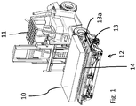
- a sheet metal stack 10 outlined as a cuboid and made up of several individual sheets is shown schematically, which has been transferred by a forklift truck 11 to an embodiment of an adjusting device 12 according to the invention in order to align the sheet metal stack 10 in a predefined position relative to a pallet 13 and place it on it.
- the sheet metal stack 10 is initially placed on support rods 14 of the adjusting device 12, the support rods 14 - here extending essentially in the form of strips in the longitudinal direction - reaching through through openings 13a of the pallet 13 from below, as can be seen in particular from FIG Fig. 7 can be seen.
- the support rods 14 are essentially rigid on one in the Fig. 1 undetectable positioning frame set, which is movable relative to the pallet 13, so that the sheet metal stack 10 can be aligned with respect to the pallet 13 in the desired manner.
- FIG. 12 shows an exploded view of the adjustment device 12 of FIG Fig. 1 .
- the support rods 14 are connected to the positioning frame 15, the positioning frame 15 being supported in a floating manner on a support frame 16 and, in contrast, being displaceable in a horizontal plane.
- the support frame 16 has on its upper side 17 facing the positioning frame 15 several ball rollers 18 on which the positioning frame 15 is supported for the purpose of its floating and sliding friction-free mounting, so that the positioning frame 15 - including the one placed there and in Fig. 2 sheet metal stack 10, not shown again - is displaceable in the horizontal plane both translationally and rotatably about vertical axes when the sheet metal stack 10 with its high weight on the support rods 14 of the positioning frame 15 rests.
- Fig. 3 is one of the ball transfer units 18 of the Fig. 2 with a partially cut-out housing 19 shown schematically.
- small balls 21 are arranged in a hemispherical shell-shaped recess 20, which balls are in direct contact with a large ball 22 arranged centered in the recess 20.
- the large ball 22 is held captive in the recess 20 by a cover 23 of the housing 19, the ball 22 partially reaching through a circular recess 24 of the cover 23.
- the positioning frame 15 rests on the large balls 22 of the ball rollers 18, which are mounted in a respective housing 19 of the ball rollers 18 by means of the small rollers 21. In this way, floating mounting of the positioning frame 15 on the support frame 16 by means of the ball rollers 18, which is subject to minimal rolling friction, is obtained, which is free of sliding friction.
- three actuators 25 in the form of linear cylinders 26, 27, 28 can also be seen, which are articulated on the one hand to the support frame 16 by being connected to it by means of joints 29.
- the linear cylinders 26, 27, 28 are connected to the positioning frame 15 by means of further joints 30 in order to be able to move the positioning frame 15 in relation to the support frame 16 as a result of changes in length of a respective linear cylinder 26, 27, 28.
- two linear cylinders 26, 27 are each arranged on opposite sides - here the transverse sides - of the support frame 16 and have one another parallel directions of action.
- the third linear cylinder 28 is arranged below the support frame 16 (cf. in particular the Fig. 5 ) and has a direction of action that is approximately perpendicular to the two other linear cylinders 26, 27, the directions of action of all actuators 26, 27, 28 being in the horizontal plane which extends parallel to the pallet 13.
- any translational movements of the positioning frame 15 in the horizontal plane including rotations of the positioning frame 15 about a variable vertical axis relative to the support frame 16 are possible.
- the positioning frame 15 is moved in a translatory manner along a first horizontal movement direction A. If the linear cylinders 26, 27 move in opposite directions, but at the same speeds, the positioning frame 15 is rotated about a vertical axis B which extends approximately in the center of the positioning frame 15.
- the positioning frame 15 is rotated about another vertical axis (not shown). In the event of a movement of the linear cylinder 28, the positioning frame 15 is moved translationally along a second horizontal direction of movement C perpendicular to the first direction of movement A, etc. Due to the articulated connections of the linear cylinders 26, 27, 28 on the one hand with the support frame 16 and on the other hand with the positioning frame 15, the linear cylinders 26, 27, 28 can move any relative movements of the positioning frame 15 with respect to the Follow the support frame 16.
- the linear cylinders 26, 27, 28 can be controlled manually and / or by means of control devices (not shown).
- the Fig. 4 shows the adjustment device 12 of FIG Fig. 2 in an oblique view from below. From this view it can be seen that all linear cylinders 26, 27, 28 are each articulated, for example, with a downwardly protruding pin 32 of the positioning frame 15 in such a way that the pins 32 transmit the movements of the linear cylinders 26, 27, 28 to the positioning frame 15 and deflect this in the manner described above. Also shows Fig. 4 two angle elements 16a, which are attached to a long side surface of the rectangular support frame 16 and overlap the support frame 16. For reasons of clarity, the angle elements 16a are shown in FIG Fig. 2 Not shown.
- the adjusting device 12 is shown in the assembled state in a view from below, from which the connections of the linear cylinders 26, 27, 28 with the support frame 16 by means of the joints 29 and the likewise articulated connections of the linear cylinders 26, 27, 28 with the positioning frame 15 by means of the joints 30 and the pin 32 can be seen.
- the arrangement of the third linear cylinder 28 below the support frame 16 can also be seen.
- the adjusting device 12 is expediently provided with a lifting device 33, which in the present exemplary embodiment is designed as a hydraulically actuated scissor lift table 34.
- the scissor lift table 34 is supported by a lower frame 35 on a base, not shown.
- Two each other crosswise Extending legs 36, 37 of equal length are movably connected to the frame 35 in such a way that the legs 36, 37 can move about a joint 38 as a common axis of rotation.
- the legs 36, 37 are connected to a support 39 which receives the support frame 16 of the adjusting device 12.
- the adjusting device 12 By moving the legs 36, 37, the support 39 and consequently the adjusting device 12 with its support frame 16 and the floating positioning frame 15 can be raised and lowered in the vertical direction 40.
- the adjusting device 12 can initially be below an in Fig. 6 Pallet 13, not shown, is arranged and raised by means of the lifting device 33 on the one hand in such a way that the support rods 14 of the positioning frame 15 reach up through the through openings 13a of the pallet 13 (workpieces can now be placed on the support rods 14 in order to adjust them), on the other hand in such a way are lowered so that the support rods 14 of the positioning frame 15 are pulled down from the through openings 13a of the pallet 13 (the adjusted workpieces can now be placed on the pallet 13), as already described above with reference to FIG Fig. 1 is explained.
- the positioning frame 15 according to Fig. 6 is associated with a frame-like support frame 42, and on which one in the Fig. 6 Pallet 13, not shown, can be stored.
- the pallet 13 is arranged in this position such that the positioning frame 15 with the support rods 14 - as described above - is movable relative to the stationary support frame 42 and consequently also relative to the pallet 13 placed thereon.
- the support frame 42 is essentially in a horizontal plane extending carriage 43 connected, which is supported by means of wheels 44 on its underside against a floor, not shown. With the carriage 43, the support frame 42 - and thus also the entire adjustment device 12 - can be moved along the floor, so that workpieces positioned on the adjustment device 12, e.g. sheet metal stacks, can be fed to their desired destination after their alignment, where they are stored and / or further can be processed.
- the Fig. 7 finally shows the adjustment system 41 with the adjustment device 12 of FIG Fig. 6 and with a pallet 13, which has been placed on the stationary support frame 42, in particular in a fixed, predetermined position and the through openings 13a of which are penetrated by the support rods 14 of the positioning frame 15, as has already been described in detail above.
Landscapes
- Engineering & Computer Science (AREA)
- Mechanical Engineering (AREA)
- Warehouses Or Storage Devices (AREA)
- Automatic Assembly (AREA)
- Pallets (AREA)
Applications Claiming Priority (1)
| Application Number | Priority Date | Filing Date | Title |
|---|---|---|---|
| DE102019004849.0A DE102019004849B3 (de) | 2019-07-12 | 2019-07-12 | Justiervorrichtung zum Ausrichten von Blechstapeln und Justiersystem mit einer solchen Justiervorrichtung |
Publications (2)
| Publication Number | Publication Date |
|---|---|
| EP3763638A1 true EP3763638A1 (fr) | 2021-01-13 |
| EP3763638B1 EP3763638B1 (fr) | 2026-05-20 |
Family
ID=71527683
Family Applications (1)
| Application Number | Title | Priority Date | Filing Date |
|---|---|---|---|
| EP20184741.5A Active EP3763638B1 (fr) | 2019-07-12 | 2020-07-08 | Système d'ajustement doté d'un dispositif d'ajustement permettant d'aligner des pièces |
Country Status (2)
| Country | Link |
|---|---|
| EP (1) | EP3763638B1 (fr) |
| DE (1) | DE102019004849B3 (fr) |
Cited By (2)
| Publication number | Priority date | Publication date | Assignee | Title |
|---|---|---|---|---|
| CN114733674A (zh) * | 2022-03-28 | 2022-07-12 | 武汉华迎汽车零部件有限公司 | 一种双工位自动喷胶设备 |
| CN116213578A (zh) * | 2023-05-11 | 2023-06-06 | 天津津荣天宇精密机械股份有限公司 | 一种辅助冲压件码放排序设备及其工作方法 |
Citations (4)
| Publication number | Priority date | Publication date | Assignee | Title |
|---|---|---|---|---|
| JPS5029230B1 (fr) * | 1970-11-24 | 1975-09-22 | ||
| US4195963A (en) * | 1978-05-23 | 1980-04-01 | Standard Folding Cartons, Inc. | Loading platform and method for transferring sheets of material |
| FR2973018A1 (fr) * | 2011-03-24 | 2012-09-28 | Peugeot Citroen Automobiles Sa | Table de depilage de flans destines a l'emboutissage, destinee a supporter une palette portant une pile de flans |
| DE102016110542A1 (de) * | 2016-06-08 | 2017-12-14 | J. Schmalz Gmbh | Be- und Entladevorrichtung für eine Maschine, Maschine zum Bearbeiten von plattenförmigen Werkstücken sowie Werkstückauflage für eine solche Maschine und Verfahren zum Be- und Entladen einer solchen Maschine |
Family Cites Families (2)
| Publication number | Priority date | Publication date | Assignee | Title |
|---|---|---|---|---|
| US6468025B1 (en) * | 1999-05-13 | 2002-10-22 | Abb Inc. | Blank separation method and apparatus |
| JP5309467B2 (ja) * | 2007-04-25 | 2013-10-09 | 村田機械株式会社 | 板材加工システム |
-
2019
- 2019-07-12 DE DE102019004849.0A patent/DE102019004849B3/de active Active
-
2020
- 2020-07-08 EP EP20184741.5A patent/EP3763638B1/fr active Active
Patent Citations (4)
| Publication number | Priority date | Publication date | Assignee | Title |
|---|---|---|---|---|
| JPS5029230B1 (fr) * | 1970-11-24 | 1975-09-22 | ||
| US4195963A (en) * | 1978-05-23 | 1980-04-01 | Standard Folding Cartons, Inc. | Loading platform and method for transferring sheets of material |
| FR2973018A1 (fr) * | 2011-03-24 | 2012-09-28 | Peugeot Citroen Automobiles Sa | Table de depilage de flans destines a l'emboutissage, destinee a supporter une palette portant une pile de flans |
| DE102016110542A1 (de) * | 2016-06-08 | 2017-12-14 | J. Schmalz Gmbh | Be- und Entladevorrichtung für eine Maschine, Maschine zum Bearbeiten von plattenförmigen Werkstücken sowie Werkstückauflage für eine solche Maschine und Verfahren zum Be- und Entladen einer solchen Maschine |
Cited By (3)
| Publication number | Priority date | Publication date | Assignee | Title |
|---|---|---|---|---|
| CN114733674A (zh) * | 2022-03-28 | 2022-07-12 | 武汉华迎汽车零部件有限公司 | 一种双工位自动喷胶设备 |
| CN116213578A (zh) * | 2023-05-11 | 2023-06-06 | 天津津荣天宇精密机械股份有限公司 | 一种辅助冲压件码放排序设备及其工作方法 |
| CN116213578B (zh) * | 2023-05-11 | 2023-07-04 | 天津津荣天宇精密机械股份有限公司 | 一种辅助冲压件码放排序设备及其工作方法 |
Also Published As
| Publication number | Publication date |
|---|---|
| DE102019004849B3 (de) | 2020-12-31 |
| EP3763638B1 (fr) | 2026-05-20 |
Similar Documents
| Publication | Publication Date | Title |
|---|---|---|
| EP3595827B1 (fr) | Dispositif de centrage | |
| DE202022002856U1 (de) | System zur Handhabung von Frachtkisten | |
| EP3250498B1 (fr) | Dispositif de retenue de charges | |
| EP2892692B1 (fr) | Système de déplacement d'une table de montage ou de soudage | |
| EP0114628B1 (fr) | Dispositif pour débosseler des containers en acier | |
| DE102019004849B3 (de) | Justiervorrichtung zum Ausrichten von Blechstapeln und Justiersystem mit einer solchen Justiervorrichtung | |
| DE2801855A1 (de) | Spieldetektor | |
| EP0066182A1 (fr) | Chariot élévateur à fourche transversale | |
| EP3924291B1 (fr) | Convoyeur pour porte-charges | |
| DE102012102208A1 (de) | Automatische Presse zum Querleimen massiver lamellenartiger Elemente | |
| DE2802345A1 (de) | Vorrichtung zum umschlagen von ladeeinheiten | |
| EP2480477B1 (fr) | Chariot cavalier destiné à être utilisé dans des terminaux à conteneurs et pour des opérations de transport générales | |
| EP0499251B1 (fr) | Gerbeur pour magasin avec deux porteurs de charge déplaçables en hauteur et commandés séparément | |
| DE4330795A1 (de) | Mobiles Lastaufnahmemittel | |
| DE2502302C3 (de) | Transportvorrichtung für Paletten | |
| EP2167405B1 (fr) | Dispositif pour charger et decharger un produit en stock | |
| DE102016000419B4 (de) | Ladewagen | |
| DE69923454T2 (de) | Vorrichtung zur Handhabung von Plattenbündeln und Tragebett zur Anwendung in einer solchen Vorrichtung | |
| EP0499250B1 (fr) | Dispositif de chargement de couches de produits pour un chariot-élévateur, monté sur un porte-charges déplaçable verticalement | |
| EP1293420B1 (fr) | Plateau élévateur contôlé par une came de commande | |
| DE202020101754U1 (de) | Wechselvorrichtung für einen Wechsel von wenigstens zwei Werkstückauflagen für eine Bearbeitungsmaschine | |
| EP0808786A2 (fr) | Dispositif de soulèvement pour rails de roulement de tables à rouleaux | |
| DE3713927A1 (de) | Scherenhebebuehne | |
| DE9306949U1 (de) | Ladevorrichtung für Lastträger | |
| DE3707187C2 (fr) |
Legal Events
| Date | Code | Title | Description |
|---|---|---|---|
| PUAI | Public reference made under article 153(3) epc to a published international application that has entered the european phase |
Free format text: ORIGINAL CODE: 0009012 |
|
| STAA | Information on the status of an ep patent application or granted ep patent |
Free format text: STATUS: THE APPLICATION HAS BEEN PUBLISHED |
|
| AK | Designated contracting states |
Kind code of ref document: A1 Designated state(s): AL AT BE BG CH CY CZ DE DK EE ES FI FR GB GR HR HU IE IS IT LI LT LU LV MC MK MT NL NO PL PT RO RS SE SI SK SM TR |
|
| AX | Request for extension of the european patent |
Extension state: BA ME |
|
| STAA | Information on the status of an ep patent application or granted ep patent |
Free format text: STATUS: REQUEST FOR EXAMINATION WAS MADE |
|
| 17P | Request for examination filed |
Effective date: 20210617 |
|
| RBV | Designated contracting states (corrected) |
Designated state(s): AL AT BE BG CH CY CZ DE DK EE ES FI FR GB GR HR HU IE IS IT LI LT LU LV MC MK MT NL NO PL PT RO RS SE SI SK SM TR |
|
| STAA | Information on the status of an ep patent application or granted ep patent |
Free format text: STATUS: EXAMINATION IS IN PROGRESS |
|
| 17Q | First examination report despatched |
Effective date: 20220530 |
|
| GRAP | Despatch of communication of intention to grant a patent |
Free format text: ORIGINAL CODE: EPIDOSNIGR1 |
|
| STAA | Information on the status of an ep patent application or granted ep patent |
Free format text: STATUS: GRANT OF PATENT IS INTENDED |
|
| INTG | Intention to grant announced |
Effective date: 20260211 |
|
| GRAS | Grant fee paid |
Free format text: ORIGINAL CODE: EPIDOSNIGR3 |
|
| GRAA | (expected) grant |
Free format text: ORIGINAL CODE: 0009210 |
|
| STAA | Information on the status of an ep patent application or granted ep patent |
Free format text: STATUS: THE PATENT HAS BEEN GRANTED |
|
| AK | Designated contracting states |
Kind code of ref document: B1 Designated state(s): AL AT BE BG CH CY CZ DE DK EE ES FI FR GB GR HR HU IE IS IT LI LT LU LV MC MK MT NL NO PL PT RO RS SE SI SK SM TR |
|
| REG | Reference to a national code |
Ref country code: CH Ref legal event code: F10 Free format text: ST27 STATUS EVENT CODE: U-0-0-F10-F00 (AS PROVIDED BY THE NATIONAL OFFICE) Effective date: 20260520 Ref country code: GB Ref legal event code: FG4D Free format text: NOT ENGLISH |
|
| REG | Reference to a national code |
Ref country code: DE Ref legal event code: R096 Ref document number: 502020013159 Country of ref document: DE |