EP3763645B1 - Dispositif d'usinage d'un empilement pourvu de composants en forme de plaque - Google Patents
Dispositif d'usinage d'un empilement pourvu de composants en forme de plaque Download PDFInfo
- Publication number
- EP3763645B1 EP3763645B1 EP19000331.9A EP19000331A EP3763645B1 EP 3763645 B1 EP3763645 B1 EP 3763645B1 EP 19000331 A EP19000331 A EP 19000331A EP 3763645 B1 EP3763645 B1 EP 3763645B1
- Authority
- EP
- European Patent Office
- Prior art keywords
- plate
- shaped component
- lying
- separating
- edge
- Prior art date
- Legal status (The legal status is an assumption and is not a legal conclusion. Google has not performed a legal analysis and makes no representation as to the accuracy of the status listed.)
- Active
Links
Images





Classifications
-
- B—PERFORMING OPERATIONS; TRANSPORTING
- B65—CONVEYING; PACKING; STORING; HANDLING THIN OR FILAMENTARY MATERIAL
- B65H—HANDLING THIN OR FILAMENTARY MATERIAL, e.g. SHEETS, WEBS, CABLES
- B65H3/00—Separating articles from piles
- B65H3/24—Separating articles from piles by pushers engaging the edges of the articles
-
- B—PERFORMING OPERATIONS; TRANSPORTING
- B65—CONVEYING; PACKING; STORING; HANDLING THIN OR FILAMENTARY MATERIAL
- B65G—TRANSPORT OR STORAGE DEVICES, e.g. CONVEYORS FOR LOADING OR TIPPING, SHOP CONVEYOR SYSTEMS OR PNEUMATIC TUBE CONVEYORS
- B65G59/00—De-stacking of articles
- B65G59/02—De-stacking from the top of the stack
- B65G59/04—De-stacking from the top of the stack by suction or magnetic devices
- B65G59/045—De-stacking from the top of the stack by suction or magnetic devices with a stepwise upward movement of the stack
-
- B—PERFORMING OPERATIONS; TRANSPORTING
- B65—CONVEYING; PACKING; STORING; HANDLING THIN OR FILAMENTARY MATERIAL
- B65H—HANDLING THIN OR FILAMENTARY MATERIAL, e.g. SHEETS, WEBS, CABLES
- B65H1/00—Supports or magazines for piles from which articles are to be separated
- B65H1/08—Supports or magazines for piles from which articles are to be separated with means for advancing the articles to present the articles to the separating device
- B65H1/14—Supports or magazines for piles from which articles are to be separated with means for advancing the articles to present the articles to the separating device comprising positively-acting mechanical devices
-
- B—PERFORMING OPERATIONS; TRANSPORTING
- B65—CONVEYING; PACKING; STORING; HANDLING THIN OR FILAMENTARY MATERIAL
- B65H—HANDLING THIN OR FILAMENTARY MATERIAL, e.g. SHEETS, WEBS, CABLES
- B65H3/00—Separating articles from piles
- B65H3/08—Separating articles from piles using pneumatic force
- B65H3/0808—Suction grippers
- B65H3/0816—Suction grippers separating from the top of pile
- B65H3/0825—Suction grippers separating from the top of pile and acting on the rear part of the articles relatively to the final separating direction
-
- B—PERFORMING OPERATIONS; TRANSPORTING
- B65—CONVEYING; PACKING; STORING; HANDLING THIN OR FILAMENTARY MATERIAL
- B65H—HANDLING THIN OR FILAMENTARY MATERIAL, e.g. SHEETS, WEBS, CABLES
- B65H3/00—Separating articles from piles
- B65H3/08—Separating articles from piles using pneumatic force
- B65H3/0808—Suction grippers
- B65H3/0883—Construction of suction grippers or their holding devices
-
- B—PERFORMING OPERATIONS; TRANSPORTING
- B65—CONVEYING; PACKING; STORING; HANDLING THIN OR FILAMENTARY MATERIAL
- B65H—HANDLING THIN OR FILAMENTARY MATERIAL, e.g. SHEETS, WEBS, CABLES
- B65H2511/00—Dimensions; Position; Numbers; Identification; Occurrences
- B65H2511/10—Size; Dimensions
- B65H2511/13—Thickness
-
- B—PERFORMING OPERATIONS; TRANSPORTING
- B65—CONVEYING; PACKING; STORING; HANDLING THIN OR FILAMENTARY MATERIAL
- B65H—HANDLING THIN OR FILAMENTARY MATERIAL, e.g. SHEETS, WEBS, CABLES
- B65H2511/00—Dimensions; Position; Numbers; Identification; Occurrences
- B65H2511/40—Identification
- B65H2511/414—Identification of mode of operation
Definitions
- the present invention relates to a device for processing a stack with plate-shaped components, with a separating device with which a plate-shaped component can be removed from the stack, the separating device being designed as a separating traverse which is mounted to be movable in at least two directions on a multi-axis handling device and has a plurality of separating means, with a lifting device for lifting the stack and with a control device for controlling the separating device and the lifting device, the plurality of separating means having at least one first separating means and at least one second separating means that are different from one another.
- Such a device for processing a stack with plate-shaped components is from DE 28 40 677 A1 known and is widely used today in the manufacturing industry in the manufacture of series products, such as home furniture, office furniture, kitchen furniture or body parts.
- plate-shaped components of various thicknesses are used.
- the thicknesses of such plate-shaped components can, depending on the application, be in a size range from less than 2 mm to over 40 mm.
- Plate-shaped components with a thickness of less than 4 mm are flexible.
- the plate-shaped components are manufactured and stored and transported in stacks. As part of the production of series products, the edges of the plate-shaped components are cut to size within the stack, thereby creating the individual plate-shaped components Components are often connected to one another by a degree of intersection. This makes it difficult to separate them later.
- the plate-shaped components For the production of series products, the plate-shaped components have to be separated from the stack after they have been cut to size in stacks. The individual plate-shaped components are then usually transported further via conveyor lines to the next production units. But that can also be solved differently. For the present invention, the following system technology is irrelevant.
- the difficulty is that the flexible or thin plate-shaped components with low thickness and the rigid plate-shaped components with greater thickness can only be separated in different ways.
- a gripper for example a suction gripper
- simply lifting the plate-shaped component on top with the aid of a gripper carries the risk of lifting one or more plate-shaped components underneath at the same time. This risk is particularly great with thin or very light plate-shaped components.
- a gripper for example a suction gripper
- the surface of the stack often has unevenness whose topographical differences in height are greater than the thickness of the thin plate-shaped components themselves not possible over a straight separating edge.
- a suitable height setting for the stack in relation to the separating edge cannot be found.
- a thin plate-shaped component lying on top is therefore usually pulled up at the edges by a gripper or suction gripper in order to separate it from the thin plate-shaped components below.
- a gripper or suction gripper By at least partially pulling up or bending up the thin plate-shaped component located above, air can get between the thin plate-shaped component located above and the thin plate-shaped component located below or actively be blown in.
- the thin plate-shaped component lying on top can be lifted off from the thin plate-shaped component lying below without one or more thin plate-shaped components lying underneath remaining hanging on it.
- a resistance that arises due to the degree of cut is overcome as a result.
- the disadvantage of the device and the method of the prior art is that different devices must be provided for thin plate-shaped components and thick plate-shaped components. Since the problem of several plate-shaped components sticking to one another does not have to exclusively have something to do with the thickness, but rather, in the case of porous and permeable materials, can also affect thicker plate-shaped components, the difference in separability is intended in the context of the present invention by a "predetermined first property "and a" predetermined second property "are expressed.
- the "predetermined first property” includes, for example, air impermeability or air permeability and thicknesses of> 4 mm and flexural strength
- the "predetermined second property” includes, for example, air impermeability and thicknesses of ⁇ 4 mm and flexural softness.
- the object of the present invention is to develop a device of the type mentioned at the beginning in such a way that it can be used to separate both plate-shaped components with the predetermined first property and with the predetermined second property from a stack.
- control device activates the at least one first separating means when a first plate-shaped component lying overhead in the stack is to be separated with a predetermined first property, and activates the at least one second separating means when a first plate-shaped component lying overhead in the stack is to be separated with a predetermined second property, wherein the predetermined second property differs from the predetermined first property.
- the present invention it is possible to arrange a plurality of separating means above a stack of plate-shaped components to be separated, which can be controlled optionally via a control device in order to separate an overhead plate-shaped component of the stack from the stack.
- the respective separating means can be designed in such a way that they are activated as a function of a predetermined first or second property of the plate-shaped component to be separated and in each case lying on top of the stack.
- the plurality of separating means has at least one first separating means and at least one second separating means that are different from one another, the control device activating the at least one first separating means when a first plate-shaped component lying on top in the stack is to be separated with a predetermined first property, and which controls at least one second separating means when a first plate-shaped component lying above in the stack is to be separated with a predetermined second property, the predetermined second property being different from the different predetermined first property.
- the present invention can also be used to separate unmixed stacks of plate-shaped components with predetermined first and second properties.
- a further advantage of the present invention is that the at least one first separating means is a push-off unit which is mounted on the separating device so that it can be lowered and has a push-off edge which, in a working position, rests against a first plate edge of the first plate-shaped component that is to be separated overhead and has the first property .
- the push-off edge lying on the first plate edge can push the first plate-shaped component lying on top in front of it when the movement of the separating device is controlled in the x-direction.
- Another advantage of the present invention is that the at least one first separating means is mounted in a vertically resilient manner in the working position. Because by a contact pressure of the first separating means on the first above Plate-shaped component can also be applied in a manner that is gentle on the material, taking into account the dimensional tolerances of the plate-shaped component.
- a further advantage of the present invention is that a separating edge is arranged on a second plate edge of the first plate-shaped component lying above to be separated, the control device controlling the lifting device in such a way that the separating edge is below the second plate edge of the first plate-shaped component lying above to be separated is located.
- the at least one second separating means is a push-off unit which is mounted on the separating device so that it can be lowered and has a gripper which, in a working position, is attached to an area of an upper side of the first plate-shaped component that is to be separated and has a second property attacks near a first plate edge.
- Such a first plate-shaped component located at the top is therefore not attacked on a first plate edge, as is the case with the first separating means, but on an area of an upper side of the top to be separated lying first plate-shaped component in the vicinity of the first plate edge. This makes it possible to move the first plate-shaped component lying on top not only in the x-direction, but also at least partially in the z-direction.
- the gripper is movably arranged between a first gripping position and a second gripping position.
- the working position of the gripper thus comprises an extended gripping position and a retracted gripping position, so that the gripper can take the first plate-shaped component to be separated at least from the first gripping position in the z-direction into the retracted gripping position.
- the first plate-shaped component to be separated above is bent upwards at least in the area of the point of attack of the gripper, so that air can get between the first plate-shaped component to be separated and a second plate-shaped component below it.
- a connection created by a degree of cut between the first plate-shaped component located above and a second plate-shaped component located below it can be separated.
- a further advantage of the present invention is that the at least one second separating means has a stop edge against which the first plate edge of the first plate-shaped component located above to be separated can strike when the gripper in the first gripping position is against the area of the first above element to be separated plate-shaped component attacks and is in the retracted gripping position moved. This ensures that the first plate edge is not also displaced in the x direction in relation to the gripper during a movement in the z direction when the retracted gripping position is reached. This ensures the exact alignment of the first plate-shaped component located on top even in the raised position, that is to say after a movement in the z-direction.
- the at least one second separating means has a pressure roller which presses against a second plate-shaped component that is underneath the first plate-shaped component to be separated and is not to be separated when the gripper is against the area of the first above-lying component to be separated engages plate-shaped component and is in the second gripping position.
- This mechanical aid supports the separation of the first plate-shaped component located above to be separated from a second plate-shaped component located below it.
- the control device can control a movement of the separating device in the x-direction. The first plate-shaped component on top is then pushed in the x-direction over the separating edge.
- Another advantage of the present invention is that at least one air nozzle for discharging air is built into the stop edge between the first plate-shaped component located above and the second plate-shaped component located below it. As a result, the at least partial separation of the first plate-shaped component located above from the second plate-shaped component located below can be supported.
- the at least one second separating means has a pressure roller which presses against a second plate-shaped component that is below the first plate-shaped component to be separated and is not to be separated when the gripper is against the area of the first above to be separated engages plate-shaped component and is in the second gripping position.
- the pressure roller prevents the second plate-shaped component from slipping due to an increased pressure force.
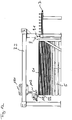
- Fig. 1 shows a perspective illustration of a device 1 for processing a stack S with plate-shaped components S1 and / or S2, in which such a stack S is provided for processing.
- the device 1 comprises a multi-axis handling device 3, which in the present embodiment is designed as a two-axis portal with a movement axis in the X direction and with a movement axis in the Z direction.
- the multi-axis handling device 3 can also be designed as a portal with more than two axes.
- the multi-axis handling device 3 encloses a space in which the stack S with a plurality of plate-shaped components S1 and / or S2 can be arranged for processing.
- the multi-axis handling device 3 also comprises a lifting device 5 on which the stack S is arranged for processing.
- the lifting device 5 can move in the Z direction.
- a control device (not shown) controls the device 1.
- the control device is part of a computer system and is programmable. In the present embodiment, the control device controls at least the lifting device 5 in such a way that it is raised or lowered as a function of a stack height. Such a control is usually adapted to certain work processes and programmed accordingly.
- the stack S is placed on the lifting device 5 with the aid of conveying means known per se.
- the device 1 separates the plate-shaped components S1 or S2 from the stack S, so that the device 1 is followed by a conveying device 7, for example a driven roller conveyor, via which the plate-shaped component S1 or S2 separated in the device 1 is conveyed away for further processing can be.
- a conveying device 7 for example a driven roller conveyor
- a separating device 100 is attached to the multi-axis handling device 3 above the stack S and can move in the multi-axis handling device 3 in the x-direction.
- the separating device 100 is movably supported with a first slide 101 and a second slide 102 on a respective longitudinal beam 3.1, 3.2 of the multi-axis handling device 3.
- the movable support takes place in the present invention by rollers, but can also be solved differently.
- the separating device 100 extends as a separating cross member parallel to a transverse bar 3.3, 3.4 of the multi-axis handling device 3, that is to say transversely to the x-direction.
- a feed roller 9 with pressure rollers 9.1 is formed to position an isolated plate-shaped component S1 or S2 in a stable position on the conveyor 7 and to have it conveyed away.
- plate-shaped components are denoted by S1 if they have a thickness (thickness) of 4 mm or greater, and denoted by S2 if these have a thickness of less than 4 mm and are flexible.
- plate-shaped components S1 are sometimes also referred to as “thick plates” and plate-shaped components S2 as “thin plates”.
- the thickness of 4 mm defined as the limit for this designation takes place within the scope of the present invention in order to make clear the problems that arise as a function of the plate thickness.
- the limit of 4 mm selected here as the limit between thin panels and thick panels can, depending on the material of the panels, also only be used with smaller thicknesses or even with greater thicknesses than 4 mm to be hit.
- the person skilled in the art will be able to recognize the thickness at which a plate-shaped component becomes so flexible that it belongs to the group of thin plates.
- the special problem associated with thin and thick plates of having to take different isolation measures can also occur with other "special properties" of the plate-shaped components S1 or S2, so that the present invention does not apply to the different isolation of thick and thin plates with one and the same Device is limited.
- the present invention makes it possible to use a separating device which is correspondingly adapted to these "special properties".
- the special property described in connection with the different strength is only one example of a plurality of special properties that may be present.
- separating device 100 is off Fig. 1 shown in a side view.
- the separating device 100 is in its position determined by the control device (not shown) at the beginning of a separating step for separating a plate-shaped component S1, that is to say in the present case a "thick plate".
- the separating device 100 is supported at the top on the multi-axis handling device 3 such that it can be moved in the x direction.
- a carrier device 103, on which a first separating means 104 is pivotably arranged, is connected to the carriages 101 and 102.
- a first pivot axis 106 assigned to the first separating means 104 ( Fig. 3 ) runs transversely to the separation direction 100 (here: transversely to the x direction).
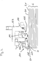
- the first separating means 104 has a push-off edge 105, which in FIG Fig. 2 position shown on At the beginning of a separation process rests against a first transverse edge Q1 of the plate-shaped component S1.
- the first separating means 104 also has an attachment shoe 107 which is attached to a support element 108 of the first separating means 104 and in which in FIG Fig. 2 position shown rests on an upper side O1 on the edge region K of the plate-shaped component S1.
- the attachment shoe 107 is resiliently mounted on the support element 108 of the first separating means 104, so that the attachment shoe 107 can yield to slight unevenness due to dimensional tolerances on the upper side O1 of the plate-shaped component S1 located at the top.
- the suspension can be designed as desired.
- the separating device 100 also comprises a second separating means 109, which is provided for separating plate-shaped components S2 and is therefore located in Fig. 2 is located in a remote position with respect to the overlying plate-shaped component S2.
- the structure and the function of the second separating means 109 will be described in more detail below in connection with the separation of a plate-shaped component S2.
- separating device 100 is shown in perspective and shows that over the transverse edge Q1 of the stack S (see also Fig. 1 ) a plurality of first separating means 104 and second separating means 109 are arranged in series.
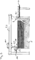
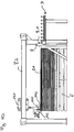
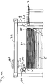
- Figures 4 , 5 and 6th shows three successive situations of a separation process in relation to a plate-shaped component S1 (here: thick plate).
- the separating device is located 100 in the in Fig. 2 shown starting position.
- the control device (not shown) has caused the separating device 100 to move into this position.
- the push-off edge 105 is on the left in Fig. 4 on the first transverse edge Q1 of the plate-shaped component S1 located at the top.
- the opposite, second transverse edge Q1 'of the plate-shaped component S1 located above is exposed above a separating edge T.
- the control device (not shown) has caused the lifting device 5 to move upwards into a position in which the overhead plate-shaped component S1 comes to lie above the separating edge T.
- the control device (not shown) therefore controls not only the separating device 100, but at least also the lifting device 5 and the conveyor device 7, the stack S always after the end of a separating process of the overlying plate-shaped component S1 lifts the stack S so far that the following The plate-shaped component S1 to be separated is now located above the separating edge T and is thus exposed at this transverse edge Q1 '.
- Fig. 5 the control device (not shown) has moved the separating device 100 to the right with the aid of the carriages 101, 102, so that the push-off edge 105 moves the plate-shaped component S1 above the separating edge T and through the feed roller 9 with pressure rollers 9.1 onto the conveyor device 7 in has shifted to the extent that the separating device 100 has moved up to then (position in Fig. 5 ) has moved.
- the self-propelled conveyor 7 takes over the conveyance of the overhead plate-shaped component S1, which has been displaced in the x-direction, and pulls it further from the stack S in the x-direction until the overhead plate-shaped component S1 is completely removed from the stack S. . Since the separation process following the in Fig.
- the control device causes the separating device 100 to return to the position shown in FIG Fig. 6 position shown moves.
- the control device controls the lifting device 5 in such a way that the stack S rises and the attachment shoe 107 of the first separating means 104 on the top O1 of the next plate-shaped component S1 lying on top is applied. In this way, all of the plate-shaped components S1 arranged in a stack S are separated one after the other.
- FIGS. 7 to 14 a separation process of a plate-shaped component S2, that is to say a thin plate, is shown in successive situations.
- the second separating means 109 is attached to a second pivot axis 110 of the separating device 100, which runs parallel to the first pivot axis.
- the second separating means 109 comprises a gripping device 111, which in the present case is a suction gripper. In other embodiments, however, the gripping device 111 could also be, for example, a magnet or entirely be trained differently.
- the gripping device 111 is displaceably attached to the second separating means 109 so that it can be retracted and extended.
- the gripping device 111 can thus move into a retracted first gripping position and an extended second gripping position or vice versa.
- the second separating means 109 also has a stop edge 112 with which a plate-shaped component S2 can be aligned.
- the second separating means 109 has a pressure roller 113 which is also designed to be retractable and extendable and the movement of which is controlled by the control device.
- Fig. 8 is a situation after the situation in Fig. 7 shown.
- the second separating means 109 has rotated about the second pivot axis 110 and lowered in such a way that the stop edge 112 rests against the transverse edge Q1 of the plate-shaped component S2 located at the top, which has slipped to the left.
- Fig. 9 is a situation of the device 1 after the in Fig. 8 shown situation.
- the control device has the separating device 100 a little moved to the right, so that the stop edge 112 in attack on the transverse edge Q1 of the laterally slipped, overhead plate-shaped component S2 has shifted this to the right so that this uppermost transverse edge Q1 is again flush with the stacking edge (all transverse edges Q1 in the stack S) of the Stack S has aligned.
- the separating device 100 is moved a little to the left again, so that the stop edge 112 is released from the stack S and frees it.
- the gripping device 111 is moved by the control device in such a way that it engages in the edge region K on the upper side O1 of the plate-shaped component S2 lying on top.
- the second separating means is pivoted upwards about the second pivot axis 110, so that the gripping device 111 pulls the plate-shaped component S2 lying on top off the stack S a little to the left and upwards.
- air is blown through air nozzles 115 in the separating device 100 between the plate-shaped component S2 lying above and a plate-shaped component S2 or S1 lying below it.
- the arrangement of the air nozzles 115 is shown in FIG Fig. 3 shown.
- Fig. 12 the pressure roller 113 is extended and comes into contact with an upper side O2 of the plate-shaped component S1 or S2 lying below the plate-shaped component S1 located at the top.
- Fig. 13 is one of the situations in Fig. 12
- the following situation is shown in which the separating device 100 is moved by the control device in the x-direction and the plate-shaped component S2 located above is pushed individually onto the conveyor 7 by the feed roller 9 with pressure rollers 9.1.
- the control device controls the second separating means 109 in such a way that it is raised ( Fig. 14 ) and back to the in Fig. 7 Moved position shown when a plate-shaped component S2 is to be separated next.
- the control device can be programmed in such a way that it recognizes which separating means 104 or 109 of the separating device 100 has to be activated in order to separate the plate-shaped component S1, S2 located above from the stack S according to its particular property.
Landscapes
- Engineering & Computer Science (AREA)
- Mechanical Engineering (AREA)
- Sheets, Magazines, And Separation Thereof (AREA)
Claims (11)
- Dispositif (1), destiné à traiter une pile (S) d'élément constitutifs (S1 ; S2) en forme de plaques, pourvu d'un système de désolidarisation (100), à l'aide duquel un élément constitutif (S1 ; S2) en forme de plaque peut être retiré de la pile (S), le système de désolidarisation (100) étant constitué sous la forme d'une traverse de désolidarisation, qui est montée sur un appareil de manipulation (3) multiaxes en étant mobile dans au moins deux directions (x, z) et qui comporte une multiplicité de moyens de désolidarisation (104 ; 109), pourvu d'un système de levage (5) destiné à lever la pile (S) et pourvu d'un système de commande, destiné à commander le système de désolidarisation (100) et le système de levage (5), la multiplicité de moyens de désolidarisation (104 ; 109) comportant au moins un premier moyen de désolidarisation (104) et au moins un deuxième moyen de désolidarisation (109) qui sont différents l'un de l'autre, caractérisé en ce que le système de commande active l'au moins un premier moyen de désolidarisation (104) lorsqu'un premier élément constitutif (S1) en forme de plaque situé sur le dessus dans la pile (S), doté d'une première propriété prédéfinie doit être désolidarisé, et active l'au moins un deuxième moyen de désolidarisation (109) lorsqu'un premier élément constitutif (S2) en forme de plaque situé sur le dessus dans la pile (S), doté d'une deuxième propriété prédéfinie doit être désolidarisé, la deuxième propriété prédéfinie se différenciant de la première propriété prédéfinie.
- Dispositif selon la revendication 1,
caractérisé
en ce que l'au moins un premier moyen de désolidarisation (104) est une unité d'évacuation latérale, qui est logée en étant abaissable sur le système de désolidarisation (100) et qui comporte une arête d'évacuation latérale (105), qui dans une position de travail est adjacente à une première arête transversale (Q1) du premier élément constitutif (S1) en forme de plaque situé sur le dessus, doté de la première propriété. - Dispositif selon la revendication 2,
caractérisé
en ce que dans la position de travail, l'au moins un premier moyen de désolidarisation (104) est logé en étant résilient en direction verticale. - Dispositif selon l'une quelconque des revendications 1 à 3,
caractérisé
en ce que l'au moins un premier moyen de désolidarisation (104) comporte un sabot de support (107), qui dans la position de travail repose sur une face supérieure (O1) du premier élément constitutif (S1) en forme de plaque situé sur le dessus qui doit être désolidarisé. - Dispositif selon l'une quelconque des revendications l à 4,
caractérisé
en ce qu'une arête de séparation (T) est placée sur une deuxième arête transversale (Q1') du premier élément constitutif (S1) en forme de plaque situé sur le dessus qui doit être désolidarisé, le système de commande commandant le système de levage (5) de sorte que la pile (S) se déplace vers le haut par rapport à l'arête de séparation (T) et que lors du processus de désolidarisation, l'arête de séparation (T) se trouve en-dessous de la deuxième arête transversale (Q') du premier élément constitutif (S1) en forme de plaque situé sur le dessus qui doit être désolidarisé. - Dispositif selon l'une quelconque des revendications l à 5,
caractérisé
en ce que l'au moins un deuxième moyen de désolidarisation (109) est une unité d'évacuation latérale, qui est logée en étant abaissable sur le système de désolidarisation (100) et qui comporte un système de préhension (111), qui dans une position de travail s'engage sur une zone d'arête (K1) d'une face supérieure (O1) du premier élément constitutif (S2) en forme de plaque situé sur le dessus qui doit être désolidarisé, doté de la deuxième propriété, à proximité d'une première arête transversale (Q1). - Dispositif selon la revendication 6,
caractérisé
en ce que le système de préhension (111) est placé en étant mobile entre une première position de préhension et une deuxième position de préhension. - Dispositif selon la revendication 7,
caractérisé
en ce que l'au moins un deuxième moyen de désolidarisation (109) comporte une arête de butée (112), sur laquelle la première arête transversale (Q1) du premier élément constitutif (S2) en forme de plaque situé sur le dessus qui doit être désolidarisé peut buter. - Dispositif selon la revendication 8,
caractérisé
en ce que dans la première position de préhension, le système de préhension (111) s'engage sur la zone du premier élément constitutif (S2) en forme de plaque situé sur le dessus qui doit être désolidarisé et se déplace dans la deuxième position de préhension, lorsque l'arête de butée (112) est adjacente à la première arête transversale (Q1). - Dispositif selon la revendication 8 ou 9,
caractérisé
en ce que dans l'arête de butée (112) est intégrée au moins une buse d'air (115) destinée à distribuer de l'air entre le premier élément constitutif (S2) en forme de plaque situé sur le dessus et le deuxième élément constitutif (S2) en forme de plaque sous-jacent. - Dispositif selon l'une quelconque des revendications 7 à 10,
caractérisé
en ce que l'au moins un deuxième moyen de désolidarisation (109) comporte un galet presseur (113), qui appuie sur un deuxième élément constitutif (S1 ; S2) en forme de plaque, qui ne doit pas être désolidarisé, situé sur le premier élément constitutif (S1 ; S2) en forme de plaque situé sur le dessus qui doit être désolidarisé, lorsque le système de préhension (111) s'engage sur la face supérieure (O1) du premier élément constitutif (S2) en forme de plaque situé sur le dessus qui doit être désolidarisé et se trouve dans la deuxième position de préhension.
Priority Applications (1)
| Application Number | Priority Date | Filing Date | Title |
|---|---|---|---|
| EP19000331.9A EP3763645B1 (fr) | 2019-07-10 | 2019-07-10 | Dispositif d'usinage d'un empilement pourvu de composants en forme de plaque |
Applications Claiming Priority (1)
| Application Number | Priority Date | Filing Date | Title |
|---|---|---|---|
| EP19000331.9A EP3763645B1 (fr) | 2019-07-10 | 2019-07-10 | Dispositif d'usinage d'un empilement pourvu de composants en forme de plaque |
Publications (2)
| Publication Number | Publication Date |
|---|---|
| EP3763645A1 EP3763645A1 (fr) | 2021-01-13 |
| EP3763645B1 true EP3763645B1 (fr) | 2021-06-30 |
Family
ID=67402782
Family Applications (1)
| Application Number | Title | Priority Date | Filing Date |
|---|---|---|---|
| EP19000331.9A Active EP3763645B1 (fr) | 2019-07-10 | 2019-07-10 | Dispositif d'usinage d'un empilement pourvu de composants en forme de plaque |
Country Status (1)
| Country | Link |
|---|---|
| EP (1) | EP3763645B1 (fr) |
Families Citing this family (2)
| Publication number | Priority date | Publication date | Assignee | Title |
|---|---|---|---|---|
| DE102022107710A1 (de) | 2022-03-31 | 2023-10-05 | Kolbus Gmbh & Co. Kg | Vorrichtung zum Vereinzeln eines zuoberst liegenden Bogens |
| DE102024128387A1 (de) * | 2024-10-01 | 2026-04-02 | Powerco Se | Vorrichtung und Verfahren zur Entnahme von Elektrodenblättern aus einem Magazin |
Family Cites Families (3)
| Publication number | Priority date | Publication date | Assignee | Title |
|---|---|---|---|---|
| US3067885A (en) * | 1959-02-24 | 1962-12-11 | Conrad D Kohler | Automatic panel feeder |
| DE1628974A1 (de) * | 1967-02-09 | 1971-05-06 | Hornberger Maschb Ges Ohg | Vorrichtung zum Zufuehren von Streifen,wie Holzkanten bzw.-leisten,Kunststoffstreifen,Furnierstreifen od.dgl.fuer Kantenanleimmaschinen |
| CH632468A5 (en) * | 1978-08-04 | 1982-10-15 | Erwin Jenkner | Apparatus for isolating panel-shaped workpieces |
-
2019
- 2019-07-10 EP EP19000331.9A patent/EP3763645B1/fr active Active
Also Published As
| Publication number | Publication date |
|---|---|
| EP3763645A1 (fr) | 2021-01-13 |
Similar Documents
| Publication | Publication Date | Title |
|---|---|---|
| EP2093170A1 (fr) | Procédé de séparation d'une quantité de flacons d'une multitude de flacons agencés sur plusieurs rangées et dispositif correspondant | |
| DE2846785B1 (de) | Vorrichtung zum automatischen Fuellen der Randfugen von Zwei- oder Mehrfach-Isolierglasscheiben mit einem Dichtungsmittel unter Verwendung von Fuellduesen | |
| EP2813446A1 (fr) | Dispositif et procédé destinés au transport de produits en forme de plaque | |
| EP3793790A1 (fr) | Système de traitement de plaques, procédé destiné à faire fonctionner un système de traitement de plaques, et équipement de commande et/ou de réglage | |
| EP3763645B1 (fr) | Dispositif d'usinage d'un empilement pourvu de composants en forme de plaque | |
| EP0615929A1 (fr) | Palettiseur à tourniquet | |
| EP0163255B1 (fr) | Appareil pour le chargement automatique d'une station pour laminer | |
| DE19636470A1 (de) | Vorrichtung zum Handhaben von Glasscheiben | |
| DE3211610A1 (de) | Vorrichtung zum abnehmen eines blattes von einem stapel | |
| EP3133234B1 (fr) | Procede et dispositif d'assemblage de panneaux en verre et de vitres isolantes | |
| EP3227069B1 (fr) | Installation de division de plaques pour diviser des pièces en forme de plaque et procédé pour faire fonctionner celle-ci | |
| EP3328765B1 (fr) | Dispositif de transport | |
| DE20121935U1 (de) | Verbundglasschneidanlage | |
| EP2060374B1 (fr) | Installation de fabrication pour blocs de construction à double paroi | |
| AT390026B (de) | Vorrichtung zum buntaufteilen von plattenfoermigen werkstuecken | |
| WO2008135147A1 (fr) | Système d'alimentation et procédé d'alimentation d'un dispositif d'usinage d'une machine-outil | |
| EP0841844A2 (fr) | Méthode et appareil pour générer un flux déterminé de circuits imprimés transportés horizontalement | |
| DE102009052336A1 (de) | Ladevorrichtung für Werkstoffstangen | |
| EP0489681A1 (fr) | Procédé et dispositif pour déplacer des pièces en forme de bandes ou de panneaux, empilés et juxtaposés sur une surface de support à faible coefficient de frottement | |
| EP1258440B1 (fr) | Dispositif pour positionner et séparer des pièces plattes à usiner fournies à partir d'une pile de pièces | |
| DE2559316A1 (de) | Verfahren und einrichtung zum abziehen einzelner platten oder von plattenpaketen von einem plattenstapel | |
| DE2549903B2 (de) | Vorrichtung zum vereinzeln und gleichzeitigen wenden des obersten blattes eines gleichorientierten folienstapels | |
| DE102015200727B4 (de) | Vorrichtung und Verfahren zum Positionieren einzelner Zwischenlagen eines Zwischenlagenstapels auf zugeordneten Paletten | |
| EP3845475A1 (fr) | Dispositif et procédé d'empilage des boîtes pliables et des découpes dans un puit d'empilage | |
| DE102018123907B4 (de) | Vorrichtung zum Abheben eines plattenförmigen obersten Werkstücks von einem Werkstückstapel |
Legal Events
| Date | Code | Title | Description |
|---|---|---|---|
| PUAI | Public reference made under article 153(3) epc to a published international application that has entered the european phase |
Free format text: ORIGINAL CODE: 0009012 |
|
| STAA | Information on the status of an ep patent application or granted ep patent |
Free format text: STATUS: THE APPLICATION HAS BEEN PUBLISHED |
|
| AK | Designated contracting states |
Kind code of ref document: A1 Designated state(s): AL AT BE BG CH CY CZ DE DK EE ES FI FR GB GR HR HU IE IS IT LI LT LU LV MC MK MT NL NO PL PT RO RS SE SI SK SM TR |
|
| AX | Request for extension of the european patent |
Extension state: BA ME |
|
| STAA | Information on the status of an ep patent application or granted ep patent |
Free format text: STATUS: REQUEST FOR EXAMINATION WAS MADE |
|
| 17P | Request for examination filed |
Effective date: 20210205 |
|
| RBV | Designated contracting states (corrected) |
Designated state(s): AL AT BE BG CH CY CZ DE DK EE ES FI FR GB GR HR HU IE IS IT LI LT LU LV MC MK MT NL NO PL PT RO RS SE SI SK SM TR |
|
| GRAJ | Information related to disapproval of communication of intention to grant by the applicant or resumption of examination proceedings by the epo deleted |
Free format text: ORIGINAL CODE: EPIDOSDIGR1 |
|
| STAA | Information on the status of an ep patent application or granted ep patent |
Free format text: STATUS: GRANT OF PATENT IS INTENDED |
|
| GRAP | Despatch of communication of intention to grant a patent |
Free format text: ORIGINAL CODE: EPIDOSNIGR1 |
|
| RIC1 | Information provided on ipc code assigned before grant |
Ipc: B65H 3/08 20060101ALI20210225BHEP Ipc: B65H 1/14 20060101ALI20210225BHEP Ipc: B65G 59/04 20060101ALI20210225BHEP Ipc: B65H 3/24 20060101AFI20210225BHEP |
|
| INTG | Intention to grant announced |
Effective date: 20210331 |
|
| GRAS | Grant fee paid |
Free format text: ORIGINAL CODE: EPIDOSNIGR3 |
|
| GRAA | (expected) grant |
Free format text: ORIGINAL CODE: 0009210 |
|
| STAA | Information on the status of an ep patent application or granted ep patent |
Free format text: STATUS: THE PATENT HAS BEEN GRANTED |
|
| AK | Designated contracting states |
Kind code of ref document: B1 Designated state(s): AL AT BE BG CH CY CZ DE DK EE ES FI FR GB GR HR HU IE IS IT LI LT LU LV MC MK MT NL NO PL PT RO RS SE SI SK SM TR |
|
| REG | Reference to a national code |
Ref country code: CH Ref legal event code: EP |
|
| REG | Reference to a national code |
Ref country code: AT Ref legal event code: REF Ref document number: 1406193 Country of ref document: AT Kind code of ref document: T Effective date: 20210715 |
|
| REG | Reference to a national code |
Ref country code: DE Ref legal event code: R096 Ref document number: 502019001687 Country of ref document: DE |
|
| REG | Reference to a national code |
Ref country code: IE Ref legal event code: FG4D Free format text: LANGUAGE OF EP DOCUMENT: GERMAN |
|
| REG | Reference to a national code |
Ref country code: LT Ref legal event code: MG9D |
|
| PG25 | Lapsed in a contracting state [announced via postgrant information from national office to epo] |
Ref country code: BG Free format text: LAPSE BECAUSE OF FAILURE TO SUBMIT A TRANSLATION OF THE DESCRIPTION OR TO PAY THE FEE WITHIN THE PRESCRIBED TIME-LIMIT Effective date: 20210930 Ref country code: FI Free format text: LAPSE BECAUSE OF FAILURE TO SUBMIT A TRANSLATION OF THE DESCRIPTION OR TO PAY THE FEE WITHIN THE PRESCRIBED TIME-LIMIT Effective date: 20210630 Ref country code: HR Free format text: LAPSE BECAUSE OF FAILURE TO SUBMIT A TRANSLATION OF THE DESCRIPTION OR TO PAY THE FEE WITHIN THE PRESCRIBED TIME-LIMIT Effective date: 20210630 |
|
| REG | Reference to a national code |
Ref country code: NL Ref legal event code: MP Effective date: 20210630 |
|
| PG25 | Lapsed in a contracting state [announced via postgrant information from national office to epo] |
Ref country code: RS Free format text: LAPSE BECAUSE OF FAILURE TO SUBMIT A TRANSLATION OF THE DESCRIPTION OR TO PAY THE FEE WITHIN THE PRESCRIBED TIME-LIMIT Effective date: 20210630 Ref country code: SE Free format text: LAPSE BECAUSE OF FAILURE TO SUBMIT A TRANSLATION OF THE DESCRIPTION OR TO PAY THE FEE WITHIN THE PRESCRIBED TIME-LIMIT Effective date: 20210630 Ref country code: LV Free format text: LAPSE BECAUSE OF FAILURE TO SUBMIT A TRANSLATION OF THE DESCRIPTION OR TO PAY THE FEE WITHIN THE PRESCRIBED TIME-LIMIT Effective date: 20210630 Ref country code: NO Free format text: LAPSE BECAUSE OF FAILURE TO SUBMIT A TRANSLATION OF THE DESCRIPTION OR TO PAY THE FEE WITHIN THE PRESCRIBED TIME-LIMIT Effective date: 20210930 Ref country code: GR Free format text: LAPSE BECAUSE OF FAILURE TO SUBMIT A TRANSLATION OF THE DESCRIPTION OR TO PAY THE FEE WITHIN THE PRESCRIBED TIME-LIMIT Effective date: 20211001 |
|
| PG25 | Lapsed in a contracting state [announced via postgrant information from national office to epo] |
Ref country code: SK Free format text: LAPSE BECAUSE OF FAILURE TO SUBMIT A TRANSLATION OF THE DESCRIPTION OR TO PAY THE FEE WITHIN THE PRESCRIBED TIME-LIMIT Effective date: 20210630 Ref country code: EE Free format text: LAPSE BECAUSE OF FAILURE TO SUBMIT A TRANSLATION OF THE DESCRIPTION OR TO PAY THE FEE WITHIN THE PRESCRIBED TIME-LIMIT Effective date: 20210630 Ref country code: ES Free format text: LAPSE BECAUSE OF FAILURE TO SUBMIT A TRANSLATION OF THE DESCRIPTION OR TO PAY THE FEE WITHIN THE PRESCRIBED TIME-LIMIT Effective date: 20210630 Ref country code: SM Free format text: LAPSE BECAUSE OF FAILURE TO SUBMIT A TRANSLATION OF THE DESCRIPTION OR TO PAY THE FEE WITHIN THE PRESCRIBED TIME-LIMIT Effective date: 20210630 Ref country code: RO Free format text: LAPSE BECAUSE OF FAILURE TO SUBMIT A TRANSLATION OF THE DESCRIPTION OR TO PAY THE FEE WITHIN THE PRESCRIBED TIME-LIMIT Effective date: 20210630 Ref country code: PT Free format text: LAPSE BECAUSE OF FAILURE TO SUBMIT A TRANSLATION OF THE DESCRIPTION OR TO PAY THE FEE WITHIN THE PRESCRIBED TIME-LIMIT Effective date: 20211102 Ref country code: NL Free format text: LAPSE BECAUSE OF FAILURE TO SUBMIT A TRANSLATION OF THE DESCRIPTION OR TO PAY THE FEE WITHIN THE PRESCRIBED TIME-LIMIT Effective date: 20210630 Ref country code: CZ Free format text: LAPSE BECAUSE OF FAILURE TO SUBMIT A TRANSLATION OF THE DESCRIPTION OR TO PAY THE FEE WITHIN THE PRESCRIBED TIME-LIMIT Effective date: 20210630 |
|
| PG25 | Lapsed in a contracting state [announced via postgrant information from national office to epo] |
Ref country code: PL Free format text: LAPSE BECAUSE OF FAILURE TO SUBMIT A TRANSLATION OF THE DESCRIPTION OR TO PAY THE FEE WITHIN THE PRESCRIBED TIME-LIMIT Effective date: 20210630 |
|
| REG | Reference to a national code |
Ref country code: DE Ref legal event code: R097 Ref document number: 502019001687 Country of ref document: DE |
|
| PG25 | Lapsed in a contracting state [announced via postgrant information from national office to epo] |
Ref country code: MC Free format text: LAPSE BECAUSE OF FAILURE TO SUBMIT A TRANSLATION OF THE DESCRIPTION OR TO PAY THE FEE WITHIN THE PRESCRIBED TIME-LIMIT Effective date: 20210630 |
|
| REG | Reference to a national code |
Ref country code: BE Ref legal event code: MM Effective date: 20210731 |
|
| PG25 | Lapsed in a contracting state [announced via postgrant information from national office to epo] |
Ref country code: DK Free format text: LAPSE BECAUSE OF FAILURE TO SUBMIT A TRANSLATION OF THE DESCRIPTION OR TO PAY THE FEE WITHIN THE PRESCRIBED TIME-LIMIT Effective date: 20210630 |
|
| PLBE | No opposition filed within time limit |
Free format text: ORIGINAL CODE: 0009261 |
|
| STAA | Information on the status of an ep patent application or granted ep patent |
Free format text: STATUS: NO OPPOSITION FILED WITHIN TIME LIMIT |
|
| PG25 | Lapsed in a contracting state [announced via postgrant information from national office to epo] |
Ref country code: LU Free format text: LAPSE BECAUSE OF NON-PAYMENT OF DUE FEES Effective date: 20210710 Ref country code: AL Free format text: LAPSE BECAUSE OF FAILURE TO SUBMIT A TRANSLATION OF THE DESCRIPTION OR TO PAY THE FEE WITHIN THE PRESCRIBED TIME-LIMIT Effective date: 20210630 |
|
| 26N | No opposition filed |
Effective date: 20220331 |
|
| PG25 | Lapsed in a contracting state [announced via postgrant information from national office to epo] |
Ref country code: IT Free format text: LAPSE BECAUSE OF FAILURE TO SUBMIT A TRANSLATION OF THE DESCRIPTION OR TO PAY THE FEE WITHIN THE PRESCRIBED TIME-LIMIT Effective date: 20210630 Ref country code: IE Free format text: LAPSE BECAUSE OF NON-PAYMENT OF DUE FEES Effective date: 20210710 Ref country code: FR Free format text: LAPSE BECAUSE OF NON-PAYMENT OF DUE FEES Effective date: 20210830 Ref country code: BE Free format text: LAPSE BECAUSE OF NON-PAYMENT OF DUE FEES Effective date: 20210731 |
|
| REG | Reference to a national code |
Ref country code: CH Ref legal event code: PL |
|
| PG25 | Lapsed in a contracting state [announced via postgrant information from national office to epo] |
Ref country code: LT Free format text: LAPSE BECAUSE OF FAILURE TO SUBMIT A TRANSLATION OF THE DESCRIPTION OR TO PAY THE FEE WITHIN THE PRESCRIBED TIME-LIMIT Effective date: 20210630 Ref country code: LI Free format text: LAPSE BECAUSE OF NON-PAYMENT OF DUE FEES Effective date: 20220731 Ref country code: CH Free format text: LAPSE BECAUSE OF NON-PAYMENT OF DUE FEES Effective date: 20220731 |
|
| PG25 | Lapsed in a contracting state [announced via postgrant information from national office to epo] |
Ref country code: CY Free format text: LAPSE BECAUSE OF FAILURE TO SUBMIT A TRANSLATION OF THE DESCRIPTION OR TO PAY THE FEE WITHIN THE PRESCRIBED TIME-LIMIT Effective date: 20210630 |
|
| PG25 | Lapsed in a contracting state [announced via postgrant information from national office to epo] |
Ref country code: HU Free format text: LAPSE BECAUSE OF FAILURE TO SUBMIT A TRANSLATION OF THE DESCRIPTION OR TO PAY THE FEE WITHIN THE PRESCRIBED TIME-LIMIT; INVALID AB INITIO Effective date: 20190710 |
|
| GBPC | Gb: european patent ceased through non-payment of renewal fee |
Effective date: 20230710 |
|
| PG25 | Lapsed in a contracting state [announced via postgrant information from national office to epo] |
Ref country code: MK Free format text: LAPSE BECAUSE OF FAILURE TO SUBMIT A TRANSLATION OF THE DESCRIPTION OR TO PAY THE FEE WITHIN THE PRESCRIBED TIME-LIMIT Effective date: 20210630 Ref country code: GB Free format text: LAPSE BECAUSE OF NON-PAYMENT OF DUE FEES Effective date: 20230710 |
|
| PG25 | Lapsed in a contracting state [announced via postgrant information from national office to epo] |
Ref country code: TR Free format text: LAPSE BECAUSE OF FAILURE TO SUBMIT A TRANSLATION OF THE DESCRIPTION OR TO PAY THE FEE WITHIN THE PRESCRIBED TIME-LIMIT Effective date: 20210630 |
|
| PG25 | Lapsed in a contracting state [announced via postgrant information from national office to epo] |
Ref country code: MT Free format text: LAPSE BECAUSE OF FAILURE TO SUBMIT A TRANSLATION OF THE DESCRIPTION OR TO PAY THE FEE WITHIN THE PRESCRIBED TIME-LIMIT Effective date: 20210630 |
|
| REG | Reference to a national code |
Ref country code: AT Ref legal event code: MM01 Ref document number: 1406193 Country of ref document: AT Kind code of ref document: T Effective date: 20240710 |
|
| PGFP | Annual fee paid to national office [announced via postgrant information from national office to epo] |
Ref country code: DE Payment date: 20250722 Year of fee payment: 7 |
|
| PG25 | Lapsed in a contracting state [announced via postgrant information from national office to epo] |
Ref country code: AT Free format text: LAPSE BECAUSE OF NON-PAYMENT OF DUE FEES Effective date: 20240710 |
|
| PGFP | Annual fee paid to national office [announced via postgrant information from national office to epo] |
Ref country code: AT Payment date: 20260410 Year of fee payment: 5 |