EP3763879A1 - Dispositif, de préférence d'encastrement, affleurant la surface de la chaussée - Google Patents
Dispositif, de préférence d'encastrement, affleurant la surface de la chaussée Download PDFInfo
- Publication number
- EP3763879A1 EP3763879A1 EP20175315.9A EP20175315A EP3763879A1 EP 3763879 A1 EP3763879 A1 EP 3763879A1 EP 20175315 A EP20175315 A EP 20175315A EP 3763879 A1 EP3763879 A1 EP 3763879A1
- Authority
- EP
- European Patent Office
- Prior art keywords
- cover
- frame
- compensating element
- recess
- area
- Prior art date
- Legal status (The legal status is an assumption and is not a legal conclusion. Google has not performed a legal analysis and makes no representation as to the accuracy of the status listed.)
- Granted
Links
Images




Classifications
-
- E—FIXED CONSTRUCTIONS
- E02—HYDRAULIC ENGINEERING; FOUNDATIONS; SOIL SHIFTING
- E02D—FOUNDATIONS; EXCAVATIONS; EMBANKMENTS; UNDERGROUND OR UNDERWATER STRUCTURES
- E02D29/00—Independent underground or underwater structures; Retaining walls
- E02D29/12—Manhole shafts; Other inspection or access chambers; Accessories therefor
- E02D29/14—Covers for manholes or the like; Frames for covers
-
- E—FIXED CONSTRUCTIONS
- E03—WATER SUPPLY; SEWERAGE
- E03B—INSTALLATIONS OR METHODS FOR OBTAINING, COLLECTING, OR DISTRIBUTING WATER
- E03B9/00—Methods or installations for drawing-off water
- E03B9/02—Hydrants; Arrangements of valves therein; Keys for hydrants
- E03B9/08—Underground hydrants
- E03B9/10—Protective plates or covers
Definitions
- the invention relates to a device for preferably flush installation in the road / road surface, for example a rigid or adjustable road cap, shaft, in particular a final shaft, water drain, inspection opening or the like, comprising a frame defining an opening and a cover that can be positioned with play in the frame.
- a device for preferably flush installation in the road / road surface for example a rigid or adjustable road cap, shaft, in particular a final shaft, water drain, inspection opening or the like, comprising a frame defining an opening and a cover that can be positioned with play in the frame.
- road fixtures which include, for example, street caps (including valve boxes, hydrant boxes, valve caps) and manhole covers. It is a small shaft that is used to make fittings for water, sewage, gas or district heating pipes installed below the road surface easily accessible and usable. In the street area, the caps sit approximately vertically over the fittings on the lines. Mainly it concerns gate valves for outgoing house connection lines, for the separation of line sections or connections for water extraction as underground hydrants.
- the classic street cap consists of a mostly hollow cylindrical frame that is closed on the top with a lid.
- the road cap is made either from cast iron or from plastic.
- road caps with a rigid frame there are also those that are adjustable in height. These are used in particular in asphalt road construction. Using a height-adjustable street cap, this can be installed flush with the surface in the road surface.
- street cap is to be understood in the broadest sense in the light of the invention. Ultimately, these are any inserts, manhole covers, slide caps, etc. that are built into a road surface.
- the lid is usually made of cast iron.
- the frame or the upper part in the case of height-adjustable street caps, comprising a lower part and one in the lower part insertable and displaceable upper part
- the frame for holding the cover possibly the entire upper part
- the frame for holding the cover is also made of cast iron.
- the tolerance-related relative movement between the cover and the frame leads to wear of the part made of plastic, in this case the frame.
- the present invention is therefore based on the object of designing and developing the generic device in such a way that the problems occurring in the prior art are largely eliminated, despite the tolerances. Even taking the tolerances as a basis, rattling noises should be largely eliminated both during transport and when installed, i.e. when driving over the device.
- the generic device for example a street cap, is characterized in that a substantially circumferential compensating element acts between the frame and the cover in such a way that when the cover is inserted, the play between the frame and the cover is at least reduced or a fit, preferably a Press fit is created, with the compensation element being a component that is independent of the cover and frame.
- the tolerance problem between the cover and the frame can be solved not only by cost-intensive, more precise production, ie by reducing production tolerances, but also by constructive measures that are also inexpensive.
- a component that is independent of the cover and frame is used, namely one that acts between the frame and the cover and is essentially circumferential Compensating element, when used, ie when inserting the cover into the frame, the play between the frame and the cover is at least reduced.
- a fit preferably a press fit, is preferably produced with the interposition of the compensating element.
- the compensation element is a separate component that is used between the frame and the cover. This is a substantially circumferential component which compensates for the play that exists between the cover and the frame.
- This compensation element is already installed during the transport of the pairing of the frame and cover, so that no rattling noises occur during transport.
- the cover does not have to be completely inserted into the frame during transport.
- the compensating element comes into effect as a whole, with this first as a centering element, then as a tolerance compensating element, as an anti-rattle element and also avoiding direct contact between the frame and the cover also serves as corrosion protection, at least in the insertion area, with the integration of drainage channels, etc.
- the device according to the invention with the revolving compensation element thus has multifunctional properties which, in combination, make up the invention.
- the compensation element is advantageously assigned to the cover. It can also be assigned to the frame.
- this can have a preferably cylindrical insertion area for positioning the cover in the frame.
- the insertion area can have any suitable shape, for example it can also be conical.
- the compensation element is assigned to this insertion area, ie it is not located in the upper area of the cover, for example at its edge to the frame, but rather is positioned relatively far down, for example in a circumferential groove, recess or recess of the insertion area of the cover.
- this insertion area has a recess along its circumference the compensation element is dimensioned accordingly so that it fits into the recess as an open ring in the sense of a clasp, a spring element or the like.
- the compensating element when the cover is inserted, lies opposite a contact surface of the frame, the compensating element or parts thereof being at least slightly deformed when the cover is inserted into the frame.
- the compensation element is made from a relatively soft material, in particular from plastic, preferably by injection molding.
- the contact surface assigned to the frame can be designed around the frame in the sense of a circular ring surface, with an inwardly at least slightly protruding, at least partially circumferential ring or flange area being advantageously provided. It is also conceivable that the contact surface is formed flush in the surface of the frame, i.e. as a flush part of the inner wall.
- the compensation element To facilitate handling, in particular installation and also any deformation of the compensation element required during installation, it is designed as a preferably open ring, an open centering ring, an annular open clasp, a band or the like, with slightly deforming areas being formed on the outside .
- This can be deformable ribs, webs or the like, which are preferably formed equidistantly over the circumference on the outside of the compensating element.
- the compensation element is equipped with a rotation lock.
- a rotation lock This can be designed in the form of a web, projection or the like protruding inwards, preferably into a recess or recess in the insertion area of the cover. This prevents the compensating element from shifting, for example over a recessed area of the plug-in area of the cover, and blocking or blocking this area. Secure positioning of the compensation element is guaranteed by the anti-rotation device.
- the compensating element can be designed in the sense of an open ring, in which case it can specifically be a resilient clasp, an open hoop or the like.
- a certain material-specific elasticity or spring force is essential, so that the compensating element can be inserted or clicked into the groove provided there by briefly expanding it over the insertion area of the cover.
- the compensation element Due to the rotation lock, the compensation element has a secure fit or hold in the lid and the lid can be easily inserted into the frame and pressed into place while deforming the ribs or the like, so that play between the frame and the lid is completely eliminated. Since the fit has a zonal effect due to the ribs, webs or the like, the cover can be easily removed from the frame with a suitable tool. It may be necessary to replace the compensating element so that another firm seat can be achieved again without annoying rattling noises when being driven over.
- the compensating element or the ribs of the compensating element can be equipped with a slope, a cone or the like, whereby the centering and the press fit achieved by deformation of the ribs is promoted.
- the cover can be equipped with a corresponding compensation element in the delivery state. If the cover is removed from the frame several times, the compensation element can be easily exchanged so that the cover is always firmly seated in the frame. This particularly favors the use of a cover made of cast iron in a frame also made of cast iron.
- the frame in the case of a height-adjustable road cap can be an integral part of an upper part which can be pushed into a lower part for height adjustment or adaptation to the level of the road surface. All parts can be made of cast iron. A rattling between cover and frame or upper part is eliminated by using the compensation element.
- the compensation element is made of a preferably heat-resistant plastic, preferably by injection molding. Due to the material-specific elasticity, it acts like a circular ring-shaped clasp which, for insertion into the groove formed in the insertion area of the cover, can be widened and pushed into this area from the free end and clicked into place.
- Fig. 1 shows an embodiment of a device according to the invention, the device comprising a cover 1, a frame 2 and an upper part 3.
- the frame 2 is an integral part of the upper part 3.
- the upper part 3 is used for insertion into a lower part, not shown in the figure, in a specific embodiment as a height-adjustable street cap.
- the cover 1 and the frame 2 or the upper part 3 are made of gray cast iron in the embodiment shown here.
- there are considerable tolerances between the cover 1 and the frame 2 which, without countermeasures, lead to rattling during transport and when being driven over in the installed state.
- Fig. 2 shows the arrangement Fig. 1 in a top view. The cover 1 and the frame 2 are shown.
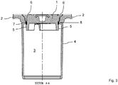
- Fig. 3 shows the arrangement Fig. 1 in a sectioned side view.
- the cover 1 is inserted into the frame 2.
- the upper part 3 extends far down with a cylindrical area 4.
- the cover 1 has a cylindrical insertion area 5 in which a circumferential groove 6 is formed in the upper area.
- a compensating element 7 is inserted into this groove 6 and acts between the cover 1 or the insertion area 5 of the cover 1 and the frame 2, more precisely against a contact surface 8 of the frame, which is designed as a circumferential ring or flange area.
- the Fig. 4 , 5 and 6th show, seen in isolation, the cover 1 with its downwardly protruding insertion area 5, the compensating element 7 being inserted there into the circumferential groove 6.
- the Fig. 4 and 6th clearly show that the compensating element 7 is an open circular ring. Ribs or webs 9 are formed on the outer surface of the compensating element 7, which can be at least slightly deformed when the cover 1 is inserted into the frame 2. It should be noted that the compensating element 7 with the ribs or webs 9 is made of plastic.
- the Figures 7a to 7f show the cover 1 with its insertion area 5 and the compensating element 7 in different views.
- the deformable ribs or webs 9 can be seen.
- a rotation lock 10 can also be seen, which is an integral part of the compensating element 7 and engages in a recess or recess in the insertion area 5 of the cover 1.
- the compensation element 7 is thus anchored in the circumferential groove 6 in a rotationally secure manner.
- FIGS 8a to 8e the compensation element 7, which is designed in the sense of an open ring or a clasp.
- Ribs or webs 9, which are arranged equidistant from one another, are formed on the outer surface of the compensating element 7.
- a web 11 is designed as a rotation lock 10, so that the compensation element 7 is seated in the circumferential groove 6 of the cover in a rotationally fixed manner.
Landscapes
- Engineering & Computer Science (AREA)
- Life Sciences & Earth Sciences (AREA)
- Environmental & Geological Engineering (AREA)
- Hydrology & Water Resources (AREA)
- Public Health (AREA)
- Water Supply & Treatment (AREA)
- Health & Medical Sciences (AREA)
- General Life Sciences & Earth Sciences (AREA)
- Mining & Mineral Resources (AREA)
- Paleontology (AREA)
- Civil Engineering (AREA)
- General Engineering & Computer Science (AREA)
- Structural Engineering (AREA)
- Sewage (AREA)
- Underground Structures, Protecting, Testing And Restoring Foundations (AREA)
Applications Claiming Priority (1)
| Application Number | Priority Date | Filing Date | Title |
|---|---|---|---|
| DE102019210287.5A DE102019210287A1 (de) | 2019-07-11 | 2019-07-11 | Vorrichtung zum vorzugsweise bündigen Einbau in die Straßen-/Fahrbahndecke |
Publications (2)
| Publication Number | Publication Date |
|---|---|
| EP3763879A1 true EP3763879A1 (fr) | 2021-01-13 |
| EP3763879B1 EP3763879B1 (fr) | 2022-10-26 |
Family
ID=70779429
Family Applications (1)
| Application Number | Title | Priority Date | Filing Date |
|---|---|---|---|
| EP20175315.9A Active EP3763879B1 (fr) | 2019-07-11 | 2020-05-19 | Dispositif d'encastrement de préférence affleurant la surface de la chaussée |
Country Status (2)
| Country | Link |
|---|---|
| EP (1) | EP3763879B1 (fr) |
| DE (1) | DE102019210287A1 (fr) |
Cited By (1)
| Publication number | Priority date | Publication date | Assignee | Title |
|---|---|---|---|---|
| USD1125598S1 (en) | 2023-05-24 | 2026-05-05 | Penn-Troy Manufacturing Inc. | Water supply valve box lid |
Citations (10)
| Publication number | Priority date | Publication date | Assignee | Title |
|---|---|---|---|---|
| JPS5022821B1 (fr) * | 1970-04-21 | 1975-08-02 | ||
| EP0005851A1 (fr) * | 1978-06-01 | 1979-12-12 | Passavant-Werke Ag | Elément de hausse avec couvercle utilisable comme obturateur après nettoyage de canalisations d'évacuation |
| EP0289736A1 (fr) * | 1987-05-04 | 1988-11-09 | Burger-Armaturen GmbH | Couvercle de chaussée |
| DE29905199U1 (de) * | 1999-03-22 | 1999-08-12 | GEK-Gesellschaft zur Erforschung der Kanalisationstechik mbH, 45886 Gelsenkirchen | Ausgleichsring für Schachtabdeckungen u.dgl. |
| DE102004010556B4 (de) | 2003-06-10 | 2005-10-27 | Rudi Hester | Verstellbare Straßenkappe |
| EP1655416A2 (fr) * | 2004-11-04 | 2006-05-10 | LIC Langmatz GmbH | Tampon de regard pour puits de regard, de préférence en béton |
| DE202008012318U1 (de) | 2007-09-12 | 2009-01-08 | Hofmann, Wolfgang | Höhenverstellbare Straßenkappe |
| DE102010055036A1 (de) | 2010-11-24 | 2012-05-24 | G + W Gmbh Gas- Und Wasserarmaturen Aus Kunststoff | Höhenverstellbare Straßenkappe |
| DE102011008189B4 (de) | 2011-01-10 | 2012-11-15 | G + W Gmbh Gas- Und Wasserarmaturen Aus Kunststoff | Höhenverstellbare Straßenkappe |
| DE102013203031A1 (de) | 2013-02-25 | 2014-09-11 | G + W Gmbh Gas- Und Wasserarmaturen Aus Kunststoff | Straßenkappe |
Family Cites Families (2)
| Publication number | Priority date | Publication date | Assignee | Title |
|---|---|---|---|---|
| FR2508953A1 (fr) * | 1981-07-06 | 1983-01-07 | Pont A Mousson | Regard de chaussee |
| DE102006055035A1 (de) * | 2006-11-22 | 2008-06-05 | Hawle Armaturen Gmbh | Straßenkappen-Deckel-Lagerungssystem mit Kunststoff-Deckelsitz |
-
2019
- 2019-07-11 DE DE102019210287.5A patent/DE102019210287A1/de not_active Ceased
-
2020
- 2020-05-19 EP EP20175315.9A patent/EP3763879B1/fr active Active
Patent Citations (10)
| Publication number | Priority date | Publication date | Assignee | Title |
|---|---|---|---|---|
| JPS5022821B1 (fr) * | 1970-04-21 | 1975-08-02 | ||
| EP0005851A1 (fr) * | 1978-06-01 | 1979-12-12 | Passavant-Werke Ag | Elément de hausse avec couvercle utilisable comme obturateur après nettoyage de canalisations d'évacuation |
| EP0289736A1 (fr) * | 1987-05-04 | 1988-11-09 | Burger-Armaturen GmbH | Couvercle de chaussée |
| DE29905199U1 (de) * | 1999-03-22 | 1999-08-12 | GEK-Gesellschaft zur Erforschung der Kanalisationstechik mbH, 45886 Gelsenkirchen | Ausgleichsring für Schachtabdeckungen u.dgl. |
| DE102004010556B4 (de) | 2003-06-10 | 2005-10-27 | Rudi Hester | Verstellbare Straßenkappe |
| EP1655416A2 (fr) * | 2004-11-04 | 2006-05-10 | LIC Langmatz GmbH | Tampon de regard pour puits de regard, de préférence en béton |
| DE202008012318U1 (de) | 2007-09-12 | 2009-01-08 | Hofmann, Wolfgang | Höhenverstellbare Straßenkappe |
| DE102010055036A1 (de) | 2010-11-24 | 2012-05-24 | G + W Gmbh Gas- Und Wasserarmaturen Aus Kunststoff | Höhenverstellbare Straßenkappe |
| DE102011008189B4 (de) | 2011-01-10 | 2012-11-15 | G + W Gmbh Gas- Und Wasserarmaturen Aus Kunststoff | Höhenverstellbare Straßenkappe |
| DE102013203031A1 (de) | 2013-02-25 | 2014-09-11 | G + W Gmbh Gas- Und Wasserarmaturen Aus Kunststoff | Straßenkappe |
Cited By (1)
| Publication number | Priority date | Publication date | Assignee | Title |
|---|---|---|---|---|
| USD1125598S1 (en) | 2023-05-24 | 2026-05-05 | Penn-Troy Manufacturing Inc. | Water supply valve box lid |
Also Published As
| Publication number | Publication date |
|---|---|
| DE102019210287A1 (de) | 2021-01-14 |
| EP3763879B1 (fr) | 2022-10-26 |
Similar Documents
| Publication | Publication Date | Title |
|---|---|---|
| EP2474671B1 (fr) | Couvercle de chaussée réglable en hauteur | |
| EP2636803B1 (fr) | Boîtier d'encastrement de robinetterie avec compensation de l'épaisseur du plâtre | |
| DE202008012318U1 (de) | Höhenverstellbare Straßenkappe | |
| EP2230359A2 (fr) | Ensemble pour la liaison d'un puits d'inspection et d'une conduite d'évacuation | |
| DE102010055036A1 (de) | Höhenverstellbare Straßenkappe | |
| EP2530365B1 (fr) | Garniture de soupape pour une armature sanitaire | |
| DE102012203394B4 (de) | Anschlussblock für Sanitärarmaturen | |
| DE60108243T2 (de) | Spender mit befestigungsorgan und umlaufender dichtung | |
| DE102013203031A1 (de) | Straßenkappe | |
| DE20118252U1 (de) | Einsatzelement für Abflüsse von Wannen, Spülen o.dgl. | |
| DE102013110452A1 (de) | Schachtabdeckung | |
| EP3763879B1 (fr) | Dispositif d'encastrement de préférence affleurant la surface de la chaussée | |
| EP3763880B1 (fr) | Dispositif, de préférence d'encastrement affleurant la surface de la chaussée | |
| DE102008052285A1 (de) | Ablaufvorrichtung | |
| EP0005851A1 (fr) | Elément de hausse avec couvercle utilisable comme obturateur après nettoyage de canalisations d'évacuation | |
| DE202008011272U1 (de) | Ablauf, insbesondere für bodengleiche Duschen | |
| DE102012105311A1 (de) | Bodenablauf | |
| DE102010044420B4 (de) | Zentrierdichtring für eine Sanitärarmatur, insbesondere eine Wachtischarmatur | |
| AT412790B (de) | Abdeckrosette für eine sanitäre unterputzarmatur | |
| DE102012218026B4 (de) | Höhenverstellbare Straßenkappe | |
| DE102010061370B3 (de) | Verschlusselement aus Kunststoff | |
| DE29721397U1 (de) | System zur Verwendung im Betonbau für die Herstellung von Durchführungen | |
| EP3214353A1 (fr) | Unite de tuyau pour l'aeration aussi que l'extraction des gaz d'echappement des equipments de combustion | |
| DE29716914U1 (de) | Sicherungseinrichtung mit Rohrunterbrecher und Rohrbelüfter | |
| DE29618587U1 (de) | Straßenkappe |
Legal Events
| Date | Code | Title | Description |
|---|---|---|---|
| PUAI | Public reference made under article 153(3) epc to a published international application that has entered the european phase |
Free format text: ORIGINAL CODE: 0009012 |
|
| STAA | Information on the status of an ep patent application or granted ep patent |
Free format text: STATUS: THE APPLICATION HAS BEEN PUBLISHED |
|
| AK | Designated contracting states |
Kind code of ref document: A1 Designated state(s): AL AT BE BG CH CY CZ DE DK EE ES FI FR GB GR HR HU IE IS IT LI LT LU LV MC MK MT NL NO PL PT RO RS SE SI SK SM TR |
|
| AX | Request for extension of the european patent |
Extension state: BA ME |
|
| STAA | Information on the status of an ep patent application or granted ep patent |
Free format text: STATUS: REQUEST FOR EXAMINATION WAS MADE |
|
| 17P | Request for examination filed |
Effective date: 20210624 |
|
| RBV | Designated contracting states (corrected) |
Designated state(s): AL AT BE BG CH CY CZ DE DK EE ES FI FR GB GR HR HU IE IS IT LI LT LU LV MC MK MT NL NO PL PT RO RS SE SI SK SM TR |
|
| GRAP | Despatch of communication of intention to grant a patent |
Free format text: ORIGINAL CODE: EPIDOSNIGR1 |
|
| STAA | Information on the status of an ep patent application or granted ep patent |
Free format text: STATUS: GRANT OF PATENT IS INTENDED |
|
| INTG | Intention to grant announced |
Effective date: 20220622 |
|
| GRAS | Grant fee paid |
Free format text: ORIGINAL CODE: EPIDOSNIGR3 |
|
| GRAA | (expected) grant |
Free format text: ORIGINAL CODE: 0009210 |
|
| STAA | Information on the status of an ep patent application or granted ep patent |
Free format text: STATUS: THE PATENT HAS BEEN GRANTED |
|
| AK | Designated contracting states |
Kind code of ref document: B1 Designated state(s): AL AT BE BG CH CY CZ DE DK EE ES FI FR GB GR HR HU IE IS IT LI LT LU LV MC MK MT NL NO PL PT RO RS SE SI SK SM TR |
|
| REG | Reference to a national code |
Ref country code: GB Ref legal event code: FG4D Free format text: NOT ENGLISH |
|
| REG | Reference to a national code |
Ref country code: CH Ref legal event code: EP |
|
| REG | Reference to a national code |
Ref country code: DE Ref legal event code: R096 Ref document number: 502020001882 Country of ref document: DE |
|
| REG | Reference to a national code |
Ref country code: AT Ref legal event code: REF Ref document number: 1527110 Country of ref document: AT Kind code of ref document: T Effective date: 20221115 |
|
| REG | Reference to a national code |
Ref country code: IE Ref legal event code: FG4D Free format text: LANGUAGE OF EP DOCUMENT: GERMAN |
|
| REG | Reference to a national code |
Ref country code: LT Ref legal event code: MG9D |
|
| REG | Reference to a national code |
Ref country code: NL Ref legal event code: MP Effective date: 20221026 |
|
| PG25 | Lapsed in a contracting state [announced via postgrant information from national office to epo] |
Ref country code: NL Free format text: LAPSE BECAUSE OF FAILURE TO SUBMIT A TRANSLATION OF THE DESCRIPTION OR TO PAY THE FEE WITHIN THE PRESCRIBED TIME-LIMIT Effective date: 20221026 |
|
| PG25 | Lapsed in a contracting state [announced via postgrant information from national office to epo] |
Ref country code: SE Free format text: LAPSE BECAUSE OF FAILURE TO SUBMIT A TRANSLATION OF THE DESCRIPTION OR TO PAY THE FEE WITHIN THE PRESCRIBED TIME-LIMIT Effective date: 20221026 Ref country code: PT Free format text: LAPSE BECAUSE OF FAILURE TO SUBMIT A TRANSLATION OF THE DESCRIPTION OR TO PAY THE FEE WITHIN THE PRESCRIBED TIME-LIMIT Effective date: 20230227 Ref country code: NO Free format text: LAPSE BECAUSE OF FAILURE TO SUBMIT A TRANSLATION OF THE DESCRIPTION OR TO PAY THE FEE WITHIN THE PRESCRIBED TIME-LIMIT Effective date: 20230126 Ref country code: LT Free format text: LAPSE BECAUSE OF FAILURE TO SUBMIT A TRANSLATION OF THE DESCRIPTION OR TO PAY THE FEE WITHIN THE PRESCRIBED TIME-LIMIT Effective date: 20221026 Ref country code: FI Free format text: LAPSE BECAUSE OF FAILURE TO SUBMIT A TRANSLATION OF THE DESCRIPTION OR TO PAY THE FEE WITHIN THE PRESCRIBED TIME-LIMIT Effective date: 20221026 Ref country code: ES Free format text: LAPSE BECAUSE OF FAILURE TO SUBMIT A TRANSLATION OF THE DESCRIPTION OR TO PAY THE FEE WITHIN THE PRESCRIBED TIME-LIMIT Effective date: 20221026 |
|
| PG25 | Lapsed in a contracting state [announced via postgrant information from national office to epo] |
Ref country code: RS Free format text: LAPSE BECAUSE OF FAILURE TO SUBMIT A TRANSLATION OF THE DESCRIPTION OR TO PAY THE FEE WITHIN THE PRESCRIBED TIME-LIMIT Effective date: 20221026 Ref country code: PL Free format text: LAPSE BECAUSE OF FAILURE TO SUBMIT A TRANSLATION OF THE DESCRIPTION OR TO PAY THE FEE WITHIN THE PRESCRIBED TIME-LIMIT Effective date: 20221026 Ref country code: LV Free format text: LAPSE BECAUSE OF FAILURE TO SUBMIT A TRANSLATION OF THE DESCRIPTION OR TO PAY THE FEE WITHIN THE PRESCRIBED TIME-LIMIT Effective date: 20221026 Ref country code: IS Free format text: LAPSE BECAUSE OF FAILURE TO SUBMIT A TRANSLATION OF THE DESCRIPTION OR TO PAY THE FEE WITHIN THE PRESCRIBED TIME-LIMIT Effective date: 20230226 Ref country code: HR Free format text: LAPSE BECAUSE OF FAILURE TO SUBMIT A TRANSLATION OF THE DESCRIPTION OR TO PAY THE FEE WITHIN THE PRESCRIBED TIME-LIMIT Effective date: 20221026 Ref country code: GR Free format text: LAPSE BECAUSE OF FAILURE TO SUBMIT A TRANSLATION OF THE DESCRIPTION OR TO PAY THE FEE WITHIN THE PRESCRIBED TIME-LIMIT Effective date: 20230127 |
|
| P01 | Opt-out of the competence of the unified patent court (upc) registered |
Effective date: 20230601 |
|
| REG | Reference to a national code |
Ref country code: DE Ref legal event code: R097 Ref document number: 502020001882 Country of ref document: DE |
|
| PG25 | Lapsed in a contracting state [announced via postgrant information from national office to epo] |
Ref country code: SM Free format text: LAPSE BECAUSE OF FAILURE TO SUBMIT A TRANSLATION OF THE DESCRIPTION OR TO PAY THE FEE WITHIN THE PRESCRIBED TIME-LIMIT Effective date: 20221026 Ref country code: RO Free format text: LAPSE BECAUSE OF FAILURE TO SUBMIT A TRANSLATION OF THE DESCRIPTION OR TO PAY THE FEE WITHIN THE PRESCRIBED TIME-LIMIT Effective date: 20221026 Ref country code: EE Free format text: LAPSE BECAUSE OF FAILURE TO SUBMIT A TRANSLATION OF THE DESCRIPTION OR TO PAY THE FEE WITHIN THE PRESCRIBED TIME-LIMIT Effective date: 20221026 Ref country code: DK Free format text: LAPSE BECAUSE OF FAILURE TO SUBMIT A TRANSLATION OF THE DESCRIPTION OR TO PAY THE FEE WITHIN THE PRESCRIBED TIME-LIMIT Effective date: 20221026 Ref country code: CZ Free format text: LAPSE BECAUSE OF FAILURE TO SUBMIT A TRANSLATION OF THE DESCRIPTION OR TO PAY THE FEE WITHIN THE PRESCRIBED TIME-LIMIT Effective date: 20221026 |
|
| PG25 | Lapsed in a contracting state [announced via postgrant information from national office to epo] |
Ref country code: SK Free format text: LAPSE BECAUSE OF FAILURE TO SUBMIT A TRANSLATION OF THE DESCRIPTION OR TO PAY THE FEE WITHIN THE PRESCRIBED TIME-LIMIT Effective date: 20221026 Ref country code: AL Free format text: LAPSE BECAUSE OF FAILURE TO SUBMIT A TRANSLATION OF THE DESCRIPTION OR TO PAY THE FEE WITHIN THE PRESCRIBED TIME-LIMIT Effective date: 20221026 |
|
| PLBE | No opposition filed within time limit |
Free format text: ORIGINAL CODE: 0009261 |
|
| STAA | Information on the status of an ep patent application or granted ep patent |
Free format text: STATUS: NO OPPOSITION FILED WITHIN TIME LIMIT |
|
| 26N | No opposition filed |
Effective date: 20230727 |
|
| PG25 | Lapsed in a contracting state [announced via postgrant information from national office to epo] |
Ref country code: SI Free format text: LAPSE BECAUSE OF FAILURE TO SUBMIT A TRANSLATION OF THE DESCRIPTION OR TO PAY THE FEE WITHIN THE PRESCRIBED TIME-LIMIT Effective date: 20221026 |
|
| PG25 | Lapsed in a contracting state [announced via postgrant information from national office to epo] |
Ref country code: MC Free format text: LAPSE BECAUSE OF FAILURE TO SUBMIT A TRANSLATION OF THE DESCRIPTION OR TO PAY THE FEE WITHIN THE PRESCRIBED TIME-LIMIT Effective date: 20221026 |
|
| REG | Reference to a national code |
Ref country code: BE Ref legal event code: MM Effective date: 20230531 |
|
| PG25 | Lapsed in a contracting state [announced via postgrant information from national office to epo] |
Ref country code: MC Free format text: LAPSE BECAUSE OF FAILURE TO SUBMIT A TRANSLATION OF THE DESCRIPTION OR TO PAY THE FEE WITHIN THE PRESCRIBED TIME-LIMIT Effective date: 20221026 Ref country code: LU Free format text: LAPSE BECAUSE OF NON-PAYMENT OF DUE FEES Effective date: 20230519 |
|
| REG | Reference to a national code |
Ref country code: IE Ref legal event code: MM4A |
|
| PG25 | Lapsed in a contracting state [announced via postgrant information from national office to epo] |
Ref country code: IE Free format text: LAPSE BECAUSE OF NON-PAYMENT OF DUE FEES Effective date: 20230519 |
|
| PG25 | Lapsed in a contracting state [announced via postgrant information from national office to epo] |
Ref country code: IE Free format text: LAPSE BECAUSE OF NON-PAYMENT OF DUE FEES Effective date: 20230519 |
|
| PG25 | Lapsed in a contracting state [announced via postgrant information from national office to epo] |
Ref country code: IT Free format text: LAPSE BECAUSE OF FAILURE TO SUBMIT A TRANSLATION OF THE DESCRIPTION OR TO PAY THE FEE WITHIN THE PRESCRIBED TIME-LIMIT Effective date: 20221026 Ref country code: BE Free format text: LAPSE BECAUSE OF NON-PAYMENT OF DUE FEES Effective date: 20230531 |
|
| PG25 | Lapsed in a contracting state [announced via postgrant information from national office to epo] |
Ref country code: BG Free format text: LAPSE BECAUSE OF FAILURE TO SUBMIT A TRANSLATION OF THE DESCRIPTION OR TO PAY THE FEE WITHIN THE PRESCRIBED TIME-LIMIT Effective date: 20221026 |
|
| PG25 | Lapsed in a contracting state [announced via postgrant information from national office to epo] |
Ref country code: BG Free format text: LAPSE BECAUSE OF FAILURE TO SUBMIT A TRANSLATION OF THE DESCRIPTION OR TO PAY THE FEE WITHIN THE PRESCRIBED TIME-LIMIT Effective date: 20221026 |
|
| PGFP | Annual fee paid to national office [announced via postgrant information from national office to epo] |
Ref country code: FR Payment date: 20250526 Year of fee payment: 6 |
|
| PGFP | Annual fee paid to national office [announced via postgrant information from national office to epo] |
Ref country code: CH Payment date: 20250601 Year of fee payment: 6 |
|
| PGFP | Annual fee paid to national office [announced via postgrant information from national office to epo] |
Ref country code: AT Payment date: 20250519 Year of fee payment: 6 |
|
| PG25 | Lapsed in a contracting state [announced via postgrant information from national office to epo] |
Ref country code: CY Free format text: LAPSE BECAUSE OF FAILURE TO SUBMIT A TRANSLATION OF THE DESCRIPTION OR TO PAY THE FEE WITHIN THE PRESCRIBED TIME-LIMIT; INVALID AB INITIO Effective date: 20200519 |
|
| PG25 | Lapsed in a contracting state [announced via postgrant information from national office to epo] |
Ref country code: HU Free format text: LAPSE BECAUSE OF FAILURE TO SUBMIT A TRANSLATION OF THE DESCRIPTION OR TO PAY THE FEE WITHIN THE PRESCRIBED TIME-LIMIT; INVALID AB INITIO Effective date: 20200519 |
|
| PGFP | Annual fee paid to national office [announced via postgrant information from national office to epo] |
Ref country code: DE Payment date: 20250730 Year of fee payment: 6 |
|
| PGFP | Annual fee paid to national office [announced via postgrant information from national office to epo] |
Ref country code: GB Payment date: 20250822 Year of fee payment: 6 |
|
| PG25 | Lapsed in a contracting state [announced via postgrant information from national office to epo] |
Ref country code: TR Free format text: LAPSE BECAUSE OF FAILURE TO SUBMIT A TRANSLATION OF THE DESCRIPTION OR TO PAY THE FEE WITHIN THE PRESCRIBED TIME-LIMIT Effective date: 20221026 |