EP3763884A1 - Alignement automatique de voies et balancement du train - Google Patents
Alignement automatique de voies et balancement du train Download PDFInfo
- Publication number
- EP3763884A1 EP3763884A1 EP20179491.4A EP20179491A EP3763884A1 EP 3763884 A1 EP3763884 A1 EP 3763884A1 EP 20179491 A EP20179491 A EP 20179491A EP 3763884 A1 EP3763884 A1 EP 3763884A1
- Authority
- EP
- European Patent Office
- Prior art keywords
- undercarriage
- relative
- main frame
- orientation
- ground surface
- Prior art date
- Legal status (The legal status is an assumption and is not a legal conclusion. Google has not performed a legal analysis and makes no representation as to the accuracy of the status listed.)
- Granted
Links
Images


Classifications
-
- B—PERFORMING OPERATIONS; TRANSPORTING
- B62—LAND VEHICLES FOR TRAVELLING OTHERWISE THAN ON RAILS
- B62D—MOTOR VEHICLES; TRAILERS
- B62D55/00—Endless track vehicles
- B62D55/08—Endless track units; Parts thereof
- B62D55/104—Suspension devices for wheels, rollers, bogies or frames
- B62D55/116—Attitude or position control of chassis by action on suspension, e.g. to compensate for a slope
-
- E—FIXED CONSTRUCTIONS
- E02—HYDRAULIC ENGINEERING; FOUNDATIONS; SOIL SHIFTING
- E02F—DREDGING; SOIL-SHIFTING
- E02F3/00—Dredgers; Soil-shifting machines
- E02F3/04—Dredgers; Soil-shifting machines mechanically-driven
- E02F3/28—Dredgers; Soil-shifting machines mechanically-driven with digging tools mounted on a dipper- or bucket-arm, i.e. there is either one arm or a pair of arms, e.g. dippers, buckets
- E02F3/36—Component parts
-
- E—FIXED CONSTRUCTIONS
- E02—HYDRAULIC ENGINEERING; FOUNDATIONS; SOIL SHIFTING
- E02F—DREDGING; SOIL-SHIFTING
- E02F9/00—Component parts of dredgers or soil-shifting machines, not restricted to one of the kinds covered by groups E02F3/00 - E02F7/00
- E02F9/08—Superstructures; Supports for superstructures
- E02F9/085—Ground-engaging fitting for supporting the machines while working, e.g. outriggers, legs
-
- E—FIXED CONSTRUCTIONS
- E02—HYDRAULIC ENGINEERING; FOUNDATIONS; SOIL SHIFTING
- E02F—DREDGING; SOIL-SHIFTING
- E02F9/00—Component parts of dredgers or soil-shifting machines, not restricted to one of the kinds covered by groups E02F3/00 - E02F7/00
- E02F9/08—Superstructures; Supports for superstructures
- E02F9/10—Supports for movable superstructures mounted on travelling or walking gears or on other superstructures
- E02F9/12—Slewing or traversing gears
- E02F9/121—Turntables, i.e. structure rotatable about 360°
- E02F9/123—Drives or control devices specially adapted therefor
-
- E—FIXED CONSTRUCTIONS
- E02—HYDRAULIC ENGINEERING; FOUNDATIONS; SOIL SHIFTING
- E02F—DREDGING; SOIL-SHIFTING
- E02F9/00—Component parts of dredgers or soil-shifting machines, not restricted to one of the kinds covered by groups E02F3/00 - E02F7/00
- E02F9/20—Drives; Control devices
-
- E—FIXED CONSTRUCTIONS
- E02—HYDRAULIC ENGINEERING; FOUNDATIONS; SOIL SHIFTING
- E02F—DREDGING; SOIL-SHIFTING
- E02F9/00—Component parts of dredgers or soil-shifting machines, not restricted to one of the kinds covered by groups E02F3/00 - E02F7/00
- E02F9/20—Drives; Control devices
- E02F9/2025—Particular purposes of control systems not otherwise provided for
Definitions
- the present disclosure relates to working machines of the type having a boom assembly pivotal about a generally vertical pivot axis relative to an undercarriage of the working machine.
- Working machines of this type may for example include excavator machines, feller buncher machines, front shovel machines, and others. These machines may have tracked or wheeled ground engaging units supporting the undercarriage from the ground surface. Various situations arise with such machines where the human operator needs to control the pivotal position of the boom assembly relative to the undercarriage.
- undercarriage orientation relative to the boom assembly affects machine stability and it affects the wear on the tracks during the excavating operation.
- the human operator needs to change the undercarriage orientation without disturbing the boom assembly orientation relative to the ground surface.
- the human operator may desire to align the boom assembly with the tracks so that the digging direction extends in a forward advance direction of the tracks to improve stability and to reduce wear on the tracks.
- the human operator may need to reorient the undercarriage relative to some feature of the ground surface without affecting the orientation of the boom assembly relative to the ground surface.
- the current disclosure provides improvements in automatic control systems for controlling alignment of the boom assembly and the undercarriage.
- a working machine comprises an undercarriage including first and second ground engaging units including first and second travel motors for driving the first and second ground engaging units, respectively.
- a main frame is supported from the undercarriage by a swing bearing such that the main frame is pivotable about a pivot axis relative to the undercarriage, the pivot axis being substantially vertical when a ground surface engaged by the ground engaging units is substantially horizontal.
- a swing motor is configured to pivot the main frame on the swing bearing about the pivot axis relative to the undercarriage.
- a boom extends from the main frame along a working direction of the boom.
- a pivot angle sensor is configured to provide a pivot angle signal corresponding to a pivot position of the main frame relative to the undercarriage about the pivot axis.
- a controller is configured to receive the pivot angle signal and to selectively drive the swing motor automatically to rotate the main frame about the pivot axis relative to the undercarriage to a target pivot position of the main frame relative to the undercarriage.
- a method is provided of controlling such a working machine.
- the method may include steps of:
- a working machine is shown and generally designated by the number 20.
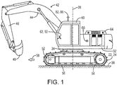
- Fig. 1 shows a tracked excavator machine 20.
- the systems disclosed herein are applicable to excavator machines, feller buncher machines, front shovel machines, and other working machines of the type having a boom assembly pivotal about a generally vertical pivot axis relative to an undercarriage of the working machine. These machines may have tracked or wheeled ground engaging units supporting the undercarriage from the ground surface.
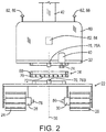
- the working machine 20 is shown in side elevation assembled view in Fig. 1 , and in rear elevation schematic partially exploded view in Fig. 2 .
- the working machine 20 includes an undercarriage 22 including first and second ground engaging units 24 and 26 including first and second travel motors 28 and 30 for driving the first and second ground engaging units 24 and 26, respectively.
- a main frame 32 is supported from the undercarriage 22 by a swing bearing 34 such that the main frame 32 is pivotable about a pivot axis 36 relative to the undercarriage.
- the pivot axis 36 is substantially vertical when a ground surface 38 engaged by the ground engaging units 24 and 26 is substantially horizontal.
- a swing motor 40 is configured to pivot the main frame 32 on the swing bearing 34 about the pivot axis 36 relative to the undercarriage 22.
- a boom assembly 42 includes a boom 44, an arm 46 pivotally connected to the boom 44, and a working tool 48.
- the boom 44 is pivotally attached to the main frame 32 to pivot about a generally horizontal axis relative to the main frame 32.
- the working tool in this embodiment is an excavator shovel 48 which is pivotally connected to the arm 46.
- the boom assembly 42 extends from the main frame 32 along a working direction 50 of the boom assembly 42.
- the working direction 50 can also be described as a working direction of the boom 44.
- the first and second ground engaging units 24 and 26 are tracked ground engaging units.
- Each of the tracked ground engaging units includes a front idler 52, a drive sprocket 54, and a track chain 56 extending around the front idler 52 and the drive sprocket 54.
- the travel motor 28 or 30 of each tracked ground engaging unit 24 or 26 drives its respective drive sprocket 54.
- Each tracked ground engaging unit has a forward traveling direction 58 defined from the drive sprocket 54 toward the front idler 52.
- the forward traveling direction 58 of the tracked ground engaging units also defines a forward traveling direction 58 of the undercarriage 22 and thus of the working machine 20.
- An operator's cab 60 may be located on the main frame 32.
- the operator's cab 60 and the boom assembly 42 may both be mounted on the main frame so that the operator's cab 60 faces in the working direction 50 of the boom assembly.
- a control station 62 may be located in the operator's cab 60.
- the engine 64 may be a diesel internal combustion engine.
- the engine 64 may drive a hydraulic pump 66 to provide hydraulic power to the various operating systems of the working machine 20.
- the engine 64, the hydraulic pump 66 and the related hydraulic power system for the working machine 20 are further illustrated schematically in Fig. 4 which is further described below.
- the swing bearing 34 as schematically shown in Fig. 2 includes an upper ring 68 configured to be bolted to the underside of the main frame 32, and a lower ring 70 configured to be bolted to the undercarriage 22.
- the lower ring 70 includes an internally toothed ring gear 72.
- the swing motor 40 is mounted on the main frame 32 and drives a pinion gear 74 which extends downward into engagement with the internally toothed ring gear 72. Operation of the swing motor 40 drives the pinioin gear 74 which results in pivoting movement of the main frame 32 on the swing bearing 34 about the pivot axis 36 relative to the undercarriage 22.
- a pivot angle sensor 76 may include an upper sensor part 76A mounted on the main frame 32 and a lower sensor part 76B mounted on the undercarriage 22.
- the pivot angle sensor 76 is configured to provide a pivot angle signal 76S (see Fig. 4 ) corresponding to a pivot position of the main frame 32 relative to the undercarriage 22 about the pivot axis 36.
- the pivot angle sensor 76 may for example be a Hall Effect rotational sensor.
- Such a Hall Effect rotational sensor may include a Hall element, a rotating shaft and a magnet. When the angular position of the Hall element changes, the corresponding changes in the magnetic field results in a linear change in output voltage.
- Other suitable types of rotary position sensors include rotary potentiometers, resolvers, optical encoders, inductive sensors and the like.
- the first and second travel motors 28 and 30 may have associated therewith first and second travel motor speed sensors 78 and 80 configured to provide first and second travel motor speed signals 78S and 80S (see Fig. 4 ), respectively, corresponding to rotational speeds of the first and second travel motors 28 and 30.
- the travel motor speed sensors 78 and 80 may for example be Hall Effect rotational sensors, or any of the alternative sensor types noted above.
- the working machine 20 may further include an orientation sensor 82 configured to provide an orientation signal 82S (see Fig. 4 ) corresponding to an orientation or a change in orientation of the orientation sensor 82 relative to the ground surface 38.
- an orientation sensor 82 configured to provide an orientation signal 82S (see Fig. 4 ) corresponding to an orientation or a change in orientation of the orientation sensor 82 relative to the ground surface 38.
- the orientation sensors 82 are shown in Fig. 1 as being fixed relative to the main frame 32, they could also be mounted on the undercarriage 22.
- orientation sensor 82 may include an inertial measurement unit (IMU) 84 mounted on the main frame 32 or the cab 60.
- IMU inertial measurement unit
- Such an IMU may be in the form of a three-axis gyroscopic unit configured to detect changes in orientation of the orientation sensor 82, and thus of the main frame 32 to which it is fixed, relative to an initial orientation.
- orientation sensor 82 may include a plurality of GPS sensing units 86, 88 fixed relative to the main frame 32 and the cab 60.
- GPS sensing units can detect the absolute position and orientation of the working machine 20 within an external reference system, and can detect changes in such position and orientation.
- orientation sensor 82 may include a camera based system which can observe surrounding structural features via image processing, and can respond to the orientation of the working machine relative to those surrounding structural features. Such a camera based orientation sensor 82 may also display to the human operator an image of the undercarriage and the surrounding ground surface 38.
- the working machine 20 includes a control system 90 including a controller 92.
- the controller 92 may be part of the machine control system of the working machine 20, or it may be a separate control module.
- the controller 92 may be mounted in the operators cab 60 at the control panel 62.
- the controller 92 is configured to receive as input signals the pivot angle signal 76S from the pivot angle sensor 76, the motor speed signals 78S and 80S from the motor speed sensors 78 and 80, and the orientation signal 82S from the orientation sensor 82.
- the signals transmitted from the various sensors to the controller 92 are schematically indicated in Fig. 4 by phantom lines connecting the sensors to the controller with an arrowhead indicating the flow of the signal from the sensor to the controller 92.
- the controller 92 will generate control signals for controlling the operation of the various actuators, which control signals are indicated schematically in Fig. 4 by phantom lines connecting the controller 92 to the various actuators with the arrow indicating the flow of the command signal from the controller 92 to the respective actuator.
- the various actuators as disclosed herein may be hydraulic motors or may be hydraulic piston-cylinder units and that the electronic control signals from the controller 92 will actually be received by electro-hydraulic control valves associated with the actuators and the electro-hydraulic control valves will control the flow of hydraulic fluid to and from the respective hydraulic actuators to control the actuation thereof in response to the control signal from the controller 92.
- the actuators may be electric actuators.
- the swing motor 40 and the first and second travel motors 28 and 30 may be electric motors.
- the control signals from the controller 92 may activate relays and switches to direct electrical power to the electric motors to drive the motors in a desired direction at a desired speed.
- the control signals 40C (see Fig. 4 ) sent to the swing motor 40 selectively drive the swing motor 40 to automatically rotate the main frame 32 about the pivot axis 36 relative to the undercarriage 22 in response to various ones of the input signals.
- Control signals 28C and 30C (see Fig. 4 ), which may be referred to as first and second travel motor speed signals, sent to the first and second travel motors 28 and 30 control a direction and speed of the first and second travel motors 28 and 30 to control a rotational movement of the undercarriage 22 relative to the ground surface 38.
- the control signals are generated at least in part in response to one or more of the input signals.
- Controller 92 includes or may be associated with a processor 94, a computer readable medium 96, a data base 98 and an input/output module or control panel 100 having a display 102.
- An input/output device 104 such as a keyboard, joystick or other user interface, is provided so that the human operator may input instructions to the controller. It is understood that the controller 92 described herein may be a single controller having all of the described functionality, or it may include multiple controllers wherein the described functionality is distributed among the multiple controllers.
- Various operations, steps or algorithms as described in connection with the controller 92 can be embodied directly in hardware, in a computer program product 106 such as a software module executed by the processor 94, or in a combination of the two.
- the computer program product 106 can reside in RAM memory, flash memory, ROM memory, EPROM memory, EEPROM memory, registers, hard disk, a removable disk, or any other form of computer-readable medium 96 known in the art.
- An exemplary computer-readable medium 96 can be coupled to the processor 94 such that the processor can read information from, and write information to, the memory/ storage medium.
- the medium can be integral to the processor.
- the processor and the medium can reside in an application specific integrated circuit (ASIC).
- the ASIC can reside in a user terminal.
- the processor and the medium can reside as discrete components in a user terminal.
- processor may refer to at least general-purpose or specific-purpose processing devices and/or logic as may be understood by one of skill in the art, including but not limited to a microprocessor, a microcontroller, a state machine, and the like.
- a processor can also be implemented as a combination of computing devices, e.g., a combination of a DSP and a microprocessor, a plurality of microprocessors, one or more microprocessors in conjunction with a DSP core, or any other such configuration.
- Fig. 4 the hydraulic fluid supply system is also illustrated, including the previously mentioned hydraulic pump 66 driven by the engine 64.
- Pump 66 takes hydraulic fluid from a tank 108 and provides pressurized hydraulic fluid to hydraulic fluid supply line 110.
- Supply line 110 is connected to a first inlet of each of the electro-hydraulic direction and flow rate control valves 28V, 30V and 40V associated first and second travel motors 28 and 30 and the swing motor 40.
- Each of the valves 28V, 30V and 40V is shown as a three position valve having a center position where there is no flow through the valve, a left side position wherein fluid flows to a first outlet port, and right side position wherein fluid flows to a second outlet port.
- the hydraulic fluid from each control valve flows to its respective hydraulic motor in the selected direction. Return fluid from the hydraulic motors flows back through the respective control valve to a return line 112 which returns the hydraulic fluid to tank 108.
- Each of the valves 28V, 30V and 40V may be a proportional control valve wherein in addition to controlling the direction of flow, the valve controls the rate of flow of hydraulic fluid, all in response to the control signals received from the controller 92.
- each of the hydraulic motors may have separate flow direction control valves and flow rate control valves associated therewith.
- the controller 92 is configured to receive the pivot angle signal 76S and to selectively drive the swing motor 40 automatically to rotate the main frame 32 about the pivot axis 36 relative to the undercarriage 22 to a target pivot position of the main frame 32 relative to the undercarriage 22.
- Fig. 5A is a schematic plan view of the machine of Fig. 1 showing a working direction of the boom aligned with a forward traveling direction of the tracks.
- Fig. 5B is a schematic plan view of the machine of Fig. 1 showing the working direction of the boom extending transversely to the forward traveling direction of the tracks.
- Fig. 5C is a schematic plan view of the machine of Fig. 1 showing the working direction of the boom parallel to but oriented 180 degrees from the forward traveling direction of the tracks.
- the controller 92 includes an automatic track alignment mode which will rotate the undercarriage 22 in place under the main frame 32, to a position wherein the working direction 50 of the boom assembly 42 or boom 44 is aligned with the forward traveling direction 58 of the working machine 20, without changing the orientation of the boom assembly 42 relative to the ground surface 38.
- the target pivot position of the main frame 32 relative to the undercarriage 22 is a pivot position wherein the forward traveling direction 58 of the ground engaging units 24 and 26 is aligned with the working direction 50 of the boom assembly 42.
- This automatic track alignment mode is schematically illustrated in the series of Figs. 6A-6C .
- Fig. 6A the working machine 20 is shown in an initial position wherein forward traveling direction 58 of the ground engaging units 24 and 26 and the working direction 50 of the boom assembly 42 are angularly offset from each other by a first angle 114. It is desired to reorient the undercarriage 22 relative to the ground surface to the position of Fig. 6C without changing the orientation of the boom assembly 42 relative to the ground surface.
- the human operator of the working machine 20 may select the automatic track alignment mode by an appropriate input to the input device 104.
- the controller 92 is configured to automatically drive both travel motors 24 and 26 to change the orientation of the undercarriage 22 relative to the ground surface 38 from the initial orientation of Fig. 6A to the final orientation of Fig. 6C by simultaneously operating the motors 24 and 26 in opposite directions at substantially equal rotational speeds and thereby rotating the undercarriage 22 through the first angle 114 relative to the ground surface 38.
- the controller 92 may generate the control signals 24C and 26C to the travel motors 24 and 26 at least in part in response to the first and second travel motor speed signals 78S and 80S to ensure that the travel motors are operating at substantially equal speeds.
- the controller 92 is also configured to automatically drive the swing motor 40 to rotate the main frame 32 about the pivot axis 36 from the initial pivot position relative to the undercarriage shown in Fig. 6A through a second angle 116 opposite and equal to the first angle 114 to the final position of Fig. 6C , simultaneously with and at substantially the same rate as the undercarriage 22 is rotated relative to the ground surface 38, so that an orientation of the main frame 32 relative to the ground surface 38 is maintained while the orientation of the undercarriage 22 relative to the ground surface 38 is changed.
- the target pivot position of the main frame 32 relative to the undercarriage 22 is a position displaced by the second angle from the initial pivot position of the main frame 32 relative to the undercarriage 22.
- Fig. 6B schematically illustrates an intermediate position between the initial position of Fig. 6A and the final position of Fig. 6C , in which intermediate position the tracks 24 and 26 are driving in opposite directions at equal speeds to rotate the undercarriage 22 clockwise, while simultaneously the swing motor 40 is driven to rotate the main frame 32 counterclockwise relative to the undercarriage 22.
- the controller 92 will also receive the input signal 76S from the pivot angle sensor 76 and will direct the simultaneous rotation of the undercarriage 22 relative to the ground surface 38 and counterrotation of the main frame 32 relative to the undercarriage 22 until the working direction 50 of the boom assembly 42 is aligned with the forward traveling direction 58 of the undercarriage 22.
- the controller 92 may be further configured to decelerate the rotation and counterrotation gradually as the target pivot position of the main frame 32 relative to the undercarriage 22 is approached.
- the controller 92 includes an undercarriage swing mode wherein the human operator can control the rotating of the undercarriage 22 relative to the ground surface 38 to any orientation selected by the human operator, while maintaining an initial orientation of the boom assembly 42 relative to the ground surface 38.
- the working machine 20 may start in an initial position as shown in Fig. 7A wherein the working direction 50 of the boom assembly 42 is aligned with the forward traveling direction 58 of the working machine 20.
- the human operator may desire to rotate the undercarriage 22 counterclockwise relative to the ground surface 38 to the final position of Fig. 7C , while maintaining the initial orientation of the boom assembly 42 relative to the ground surface 38.
- This undercarriage swing mode is schematically illustrated in the series of Figs. 7A-7C .
- the human operator of the working machine 20 may select the undercarriage swing mode by an appropriate input to the input device 104.
- the controller 92 is configured to automatically drive both travel motors 24 and 26 under a further control input from the human operator to change the orientation of the undercarriage 22 relative to the ground surface 38 from the initial orientation of Fig. 7A in a selected clockwise or counterclockwise direction by simultaneously operating the motors 24 and 26 in opposite directions at substantially equal rotational speeds. This will rotate the undercarriage 22 through a first angle 114 relative to the ground surface 38 until the rotating command is terminated by control input from the human operator.
- the controller 92 automatically drives the swing motor 40 to rotate the main frame 32 about the pivot axis 36 clockwise relative to the undercarriage 22, simultaneously with and at substantially the same rate as the undercarriage 22 is rotated relative to the ground surface 38.
- the orientation of the main frame 32 relative to the ground surface 38 is maintained while the orientation of the undercarriage 22 relative to the ground surface 38 is changed.
- the target pivot position of the main frame 32 relative to the undercarriage 22 is a position displaced by from an initial pivot position of the main frame 32 relative to the undercarriage 22 by an angle equal to and opposite from the first angle by which the human operator chooses to rotate the undercarriage 22 relative to the ground surface 38.
- Fig. 7B schematically illustrates an intermediate position between the initial position of Fig. 7A and the final position of Fig. 7C , in which intermediate position the tracks 24 and 26 are driving in opposite directions at equal speeds to rotate the undercarriage 22 counterclockwise, while simultaneously the swing motor 40 is driven to rotate the main frame 32 clockwise relative to the undercarriage 22.
- the controller 92 also includes an automatic boom alignment mode.
- the automatic boom alignment mode the human operator may wish to rotate the boom assembly 42 relative to the undercarriage 22 to a position wherein the working direction 50 of the boom assembly 42 is parallel to the forward travel direction 50, without making any change in orientation of the undercarriage 22 relative to the ground surface 38.
- the boom assembly 42 may have its working direction 50 aligned with the forward traveling direction 58 as seen in Fig. 8B , or parallel to but oriented 180 degrees from the forward traveling direction 58 of the tracks as seen in Fig. 8C .
- Such boom alignment may for example be desired prior to moving the working machine from one working location to another.
- This automatic boom alignment mode is schematically illustrated in Figs. 8A-8C .
- the human operator of the working machine 20 may select the boom alignment mode by an appropriate input to the input device 104.
- the controller 92 is configured to automatically drive the swing motor 40 at least in part in response to the input signal 76S from the pivot angle sensor 76, to either of the positions of Figs. 8B or 8C .
- the boom alignment mode may include optional inputs allowing the human operator to choose either of the final positions of Figs. 8B or 8C , or the boom alignment mode may be programmed to automatically select the closest one of the positions of Figs. 8B or 8C .
- the controller 92 may be further configured to decelerate the rotation and counterrotation gradually as the target pivot position of the main frame 32 relative to the undercarriage 22 is approached.
- the controller 92 also includes a multiple preset position mode.
- the human operator can preset a plurality of preset target pivot positions of the main frame 32 relative to the undercarriage 22, and then the human operator can select any one of the preset target pivot positions of the main frame 32 relative to the undercarriage 22.
- the operator of the excavator 20 may be excavating earth at a first orientation of the boom assembly 42 relative to the ground surface 38 as shown in Fig. 9A , depositing excavated earth to the left side on a pile with the boom assembly in a second orientation relative to the ground surface as shown in Fig. 9B , and periodically loading excavated earth to a truck located to the right side with the boom assembly 42 in a third orientation relative to the ground surface as shown in Fig. 9C .
- the human operator of the working machine 20 may select the multiple preset position mode by an appropriate input to the input device 104.
- the multiple preset position mode the human operator can place the boom assembly 42 in selected positions relative to the undercarriage 22 and "save" those positions 9A, 9B and 9C as the plurality of preset positions.
- the controller 92 will be configured to automatically pivot the boom assembly 42 from wherever it is to that preset position.
- the controller 92 is configured to automatically drive the swing motor 40 at least in part in response to the input signal 76S from the pivot angle sensor 76, to pivot the boom assembly 42 to the selected preset position.
- the controller 92 may be further configured to decelerate the rotation and counterrotation gradually as the target pivot position of the main frame 32 relative to the undercarriage 22 is approached.
- Each of the above modes of operation may be performed with or without input from one of the orientation sensors 82.
- the use of one of the orientation sensors 82 can provide an additional input to the controller 92 to further ensure that an orientation of the boom assembly 42 relative to the ground surface 38 does not change while the undercarriage 22 is reoriented relative to the ground surface.
- the controller receives an orientation signal 82S corresponding to an orientation or a change in orientation of the orientation sensor relative to the ground surface 38, and the controller 92 is configured to maintain the orientation of the main frame 32 relative to the ground surface at least in part based upon the orientation signal 82S.
- orientation sensors 82 can ensure that a desired reorientation of the undercarriage 22 relative to the ground surface 38 is achieved, regardless of slippage of one or both of the tracked ground engaging units relative to the ground surface 38 during the reorientation of the undercarriage 22.
- the IMU detects changes in orientation of the orientation sensor 82, and thus of the main frame 32 to which it is fixed, relative to an initial orientation.
- the GPS sensing units can detect the absolute position and orientation of the working machine 20 within an external reference system, and can detect changes in such position and orientation.
- the control system 90 disclosed herein may be used in connection many different working machines of the type having a boom assembly pivotal about a generally vertical pivot axis relative to an undercarriage of the working machine.
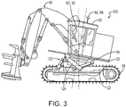
- Fig. 3 illustrates another embodiment of such a working machine embodied as a tracked feller buncher machine 120 for use in forestry for the harvesting of trees. Similar to the excavator type of working machine 20 previously described, the tracked feller buncher machine 120 has an undercarriage 22, first and second tracked ground engaging units 24 and 26, main frame 32, swing bearing 34, and boom assembly 42. The feller buncher machine 120 may include the same control system 90 just described with regard to Fig. 4 to control the orientation of its undercarriage 22 relative to the ground surface 38, and to control the orientation of its main frame 32 and boom assembly 42 relative to its undercarriage 22.
- the feller buncher machine 120 is often operated on very uneven ground such as when harvesting trees in a mountainous area.
- the feller buncher machine 120 may include a leveling mechanism 122 including a plurality of linear actuators which may be in the form of hydraulic piston-cylinder units 124 and 126 to adjust a pitch and roll of the swing bearing 34 and thus the main frame 32 relative to the undercarriage 22.
- the leveling mechanism 122 may be constructed in accordance with the teachings of U.S. Patent No. 8,180,532 , the details of which are incorporated herein by reference.
- the pivotal axis 36 is defined by the swing bearing 34 and the pivot angle sensor 76 is mounted between the upper and lower rings 68 and 70 of the swing bearing 34.
- the purpose of the leveling mechanism 122 is to maintain the operator's cab 60 in a generally horizontal orientation relative to gravity for the comfort and safety of the human operator who is operating the feller buncher machine 120.
- the controller 92 When incorporating the control system 90 in a feller buncher machine 120 including such a leveling mechanism 122, the controller 92 includes a level control mode in which the controller 92 is configured to control the extension of the various hydraulic piston-cylinder units 124 and 126 of the leveling mechanism 122, to control the pitch and roll of the swing bearing 34 at least in part based upon the pivot angle signal 76S from the pivot angle sensor 76.
- the controller 92 in the level control mode is configured to send control signals 124C and 126C to electro-hydraulic proportional control valves 124V and 126V to control the direction and rate of flow of hydraulic fluid to the hydraulic piston-cylinder units 124 and 126.
- the control signals 124C and 126C are at least in part based upon the pivot angle signal 76S from the pivot angle sensor 76.
- linear actuators 124 may be other types of linear actuators, including hydraulically or electrically powered lead screws, electrically or hydraulically powered rack and pinion, pneumatic actuators, or the like.
- One method of operation of the working machine 20 or 120 may include steps of:
- the method may further include:
- the method may further include automatically terminating the rotating of the undercarriage 22 relative to the ground surface 38 when the forward traveling direction 58 of the ground engaging units 24, 26 is aligned with the working direction 50 of the boom assembly 42.
- the method may further include terminating the rotating of the undercarriage 22 relative to the ground surface 38 by a control input from a human operator of the working machine 20, 120.
- the method may further include:
- the method may further include a step of automatically controlling the pitch and roll of the swing bearing 34 at least in part based upon the pivot position of the main frame 32 relative to the undercarriage 22 about the pivot axis 36.
- the method may further include in step (b) in the target pivot position the working direction 50 of the boom 44 being parallel to the forward traveling direction 50.
- the method may further include:
Landscapes
- Engineering & Computer Science (AREA)
- Mining & Mineral Resources (AREA)
- Civil Engineering (AREA)
- General Engineering & Computer Science (AREA)
- Structural Engineering (AREA)
- Mechanical Engineering (AREA)
- Chemical & Material Sciences (AREA)
- Combustion & Propulsion (AREA)
- Transportation (AREA)
- Operation Control Of Excavators (AREA)
Applications Claiming Priority (1)
| Application Number | Priority Date | Filing Date | Title |
|---|---|---|---|
| US16/508,948 US11577796B2 (en) | 2019-07-11 | 2019-07-11 | Auto track alignment and undercarriage swing |
Publications (2)
| Publication Number | Publication Date |
|---|---|
| EP3763884A1 true EP3763884A1 (fr) | 2021-01-13 |
| EP3763884B1 EP3763884B1 (fr) | 2023-12-13 |
Family
ID=71092409
Family Applications (1)
| Application Number | Title | Priority Date | Filing Date |
|---|---|---|---|
| EP20179491.4A Active EP3763884B1 (fr) | 2019-07-11 | 2020-06-11 | Alignement automatique de voies et balancement du train |
Country Status (4)
| Country | Link |
|---|---|
| US (1) | US11577796B2 (fr) |
| EP (1) | EP3763884B1 (fr) |
| CN (1) | CN112211238B (fr) |
| FI (1) | FI3763884T3 (fr) |
Cited By (1)
| Publication number | Priority date | Publication date | Assignee | Title |
|---|---|---|---|---|
| WO2023229466A1 (fr) | 2022-05-25 | 2023-11-30 | Felle Kim Arild | Véhicule et train de roulement réglable correspondant au véhicule |
Families Citing this family (3)
| Publication number | Priority date | Publication date | Assignee | Title |
|---|---|---|---|---|
| US12188207B2 (en) | 2021-03-05 | 2025-01-07 | Deere &Company | System and method for terrain based control of self-propelled work vehicles |
| US20220314782A1 (en) * | 2021-03-31 | 2022-10-06 | Nabtesco Corporation | Crawler drive unit and construction machine |
| CN116695818B (zh) * | 2023-06-26 | 2024-01-30 | 徐工集团工程机械股份有限公司科技分公司 | 一种含回转平台自适应静压支撑装置的挖装机及控制方法 |
Citations (4)
| Publication number | Priority date | Publication date | Assignee | Title |
|---|---|---|---|---|
| US3184867A (en) * | 1962-12-12 | 1965-05-25 | Yumbo | Earthmoving machine having protected turntable seal |
| GB2134876A (en) * | 1982-12-24 | 1984-08-22 | Kubota Ltd | Swivelling-type work vehicle |
| US4552503A (en) * | 1982-12-24 | 1985-11-12 | Kubota, Ltd. | Excavating vehicle |
| US8180532B2 (en) | 2006-05-26 | 2012-05-15 | Deere & Company | Vector controlled leveling system for a forestry machine |
Family Cites Families (13)
| Publication number | Priority date | Publication date | Assignee | Title |
|---|---|---|---|---|
| US4111066A (en) | 1976-11-10 | 1978-09-05 | Joy Manufacturing Company | Control means |
| JPH0820972A (ja) * | 1994-07-11 | 1996-01-23 | Japanic:Kk | 掘削機 |
| US6477914B1 (en) | 2000-07-24 | 2002-11-12 | Clark Equipment Company | Motion alarm |
| ITTO20021068A1 (it) * | 2002-12-06 | 2004-06-07 | Fiat Kobelco Construction Machinery S P A | Veicolo su ruote provvisto di un assale oscillante attorno ad un asse longitudinale. |
| EP2910690A1 (fr) * | 2004-11-17 | 2015-08-26 | Komatsu Ltd. | Dispositif de commande de rotation et engin de chantier |
| WO2008129345A1 (fr) | 2007-04-19 | 2008-10-30 | Volvo Compact Equipment Sas | Organe de commande d'une machine à direction à glissement |
| US8694204B2 (en) * | 2009-04-17 | 2014-04-08 | Volvo Construction Equipment Ab | Vehicle and method for operating a vehicle |
| CN103857851B (zh) * | 2011-10-19 | 2016-03-09 | 住友重机械工业株式会社 | 回转作业机械及回转作业机械的控制方法 |
| US20140172246A1 (en) * | 2012-12-14 | 2014-06-19 | Caterpillar Inc. | Automatic Swing and Radius Control System and Method for a Machine Implement |
| WO2015021400A1 (fr) * | 2013-08-08 | 2015-02-12 | Parker-Hannifin Corporation | Système d'entraînement en giration de type hybride et hydraulique pour excavatrices |
| CN204705896U (zh) * | 2015-05-18 | 2015-10-14 | 三一汽车制造有限公司 | 一种工程机械及臂架回转对中控制系统 |
| JP7027402B2 (ja) * | 2016-07-20 | 2022-03-01 | プリノート エル.ティー.ディー. | 回転式上部構造を有する履帯車両及び履帯車両用プロセス |
| EP3535458B1 (fr) * | 2016-11-02 | 2023-07-12 | Clark Equipment Company | Système et procédé pour définir une zone de fonctionnement pour un bras de levage |
-
2019
- 2019-07-11 US US16/508,948 patent/US11577796B2/en active Active
-
2020
- 2020-06-11 FI FIEP20179491.4T patent/FI3763884T3/fi active
- 2020-06-11 CN CN202010532358.4A patent/CN112211238B/zh active Active
- 2020-06-11 EP EP20179491.4A patent/EP3763884B1/fr active Active
Patent Citations (4)
| Publication number | Priority date | Publication date | Assignee | Title |
|---|---|---|---|---|
| US3184867A (en) * | 1962-12-12 | 1965-05-25 | Yumbo | Earthmoving machine having protected turntable seal |
| GB2134876A (en) * | 1982-12-24 | 1984-08-22 | Kubota Ltd | Swivelling-type work vehicle |
| US4552503A (en) * | 1982-12-24 | 1985-11-12 | Kubota, Ltd. | Excavating vehicle |
| US8180532B2 (en) | 2006-05-26 | 2012-05-15 | Deere & Company | Vector controlled leveling system for a forestry machine |
Cited By (1)
| Publication number | Priority date | Publication date | Assignee | Title |
|---|---|---|---|---|
| WO2023229466A1 (fr) | 2022-05-25 | 2023-11-30 | Felle Kim Arild | Véhicule et train de roulement réglable correspondant au véhicule |
Also Published As
| Publication number | Publication date |
|---|---|
| US11577796B2 (en) | 2023-02-14 |
| CN112211238A (zh) | 2021-01-12 |
| CN112211238B (zh) | 2023-09-12 |
| BR102020011629A2 (pt) | 2021-01-19 |
| US20210009215A1 (en) | 2021-01-14 |
| FI3763884T3 (fi) | 2024-03-15 |
| EP3763884B1 (fr) | 2023-12-13 |
Similar Documents
| Publication | Publication Date | Title |
|---|---|---|
| EP3763884B1 (fr) | Alignement automatique de voies et balancement du train | |
| US6609315B1 (en) | Automatic backhoe tool orientation control | |
| US11261578B2 (en) | Work machine | |
| US6173573B1 (en) | Control device for hydraulic drive machine | |
| US6763619B2 (en) | Automatic loader bucket orientation control | |
| US11821163B2 (en) | Shovel | |
| CN111954737A (zh) | 挖土机 | |
| KR101839467B1 (ko) | 건설 기계의 제어 시스템, 건설 기계, 및 건설 기계의 제어 방법 | |
| EP2167825B1 (fr) | Conduite avec raccordement en parallèle-en série de moteurs à deux vitesses | |
| CN113348301A (zh) | 液压泵流量校正系统 | |
| WO2019012701A1 (fr) | Engin de chantier et procédé de commande d'engin de chantier | |
| KR102422582B1 (ko) | 유압 셔블 | |
| JP7315333B2 (ja) | 建設機械の制御システム、及び建設機械の制御方法 | |
| CN113544336A (zh) | 作业机械 | |
| US11512450B2 (en) | Tracked vehicle motion correction | |
| AU2017402092A1 (en) | Work machine and method of controlling work machine | |
| EP4034716B1 (fr) | Système et procédés de gestion de temps de cycle | |
| EP4381141B1 (fr) | Commande de système hydraulique d'un engin de chantier | |
| EP3827138B1 (fr) | Hiérarchisation de puissance hydraulique | |
| WO2017138070A1 (fr) | Engin de chantier et procédé de commande d'opération | |
| US20260103871A1 (en) | Swing deceleration control system | |
| BR102020011629B1 (pt) | Máquina de trabalho, e, método para controlar uma máquina de trabalho | |
| JP5755865B2 (ja) | 油圧駆動装置および油圧駆動装置を備えた作業機械 | |
| US20240254727A1 (en) | Uninterrupted automatic position control of work implements during override of target settings | |
| US20250188701A1 (en) | Advanced precision construction features on pilot operated machines |
Legal Events
| Date | Code | Title | Description |
|---|---|---|---|
| PUAI | Public reference made under article 153(3) epc to a published international application that has entered the european phase |
Free format text: ORIGINAL CODE: 0009012 |
|
| STAA | Information on the status of an ep patent application or granted ep patent |
Free format text: STATUS: THE APPLICATION HAS BEEN PUBLISHED |
|
| AK | Designated contracting states |
Kind code of ref document: A1 Designated state(s): AL AT BE BG CH CY CZ DE DK EE ES FI FR GB GR HR HU IE IS IT LI LT LU LV MC MK MT NL NO PL PT RO RS SE SI SK SM TR |
|
| AX | Request for extension of the european patent |
Extension state: BA ME |
|
| STAA | Information on the status of an ep patent application or granted ep patent |
Free format text: STATUS: REQUEST FOR EXAMINATION WAS MADE |
|
| 17P | Request for examination filed |
Effective date: 20210713 |
|
| RBV | Designated contracting states (corrected) |
Designated state(s): AL AT BE BG CH CY CZ DE DK EE ES FI FR GB GR HR HU IE IS IT LI LT LU LV MC MK MT NL NO PL PT RO RS SE SI SK SM TR |
|
| GRAP | Despatch of communication of intention to grant a patent |
Free format text: ORIGINAL CODE: EPIDOSNIGR1 |
|
| STAA | Information on the status of an ep patent application or granted ep patent |
Free format text: STATUS: GRANT OF PATENT IS INTENDED |
|
| INTG | Intention to grant announced |
Effective date: 20230726 |
|
| RIN1 | Information on inventor provided before grant (corrected) |
Inventor name: VEASY, DAVID Inventor name: SHERLOCK, LANCE Inventor name: JADHAV, RUSHIKESH Inventor name: DONGARE, DIPANKAR Inventor name: JAGTAP, DNYANESHWAR |
|
| GRAS | Grant fee paid |
Free format text: ORIGINAL CODE: EPIDOSNIGR3 |
|
| GRAA | (expected) grant |
Free format text: ORIGINAL CODE: 0009210 |
|
| STAA | Information on the status of an ep patent application or granted ep patent |
Free format text: STATUS: THE PATENT HAS BEEN GRANTED |
|
| AK | Designated contracting states |
Kind code of ref document: B1 Designated state(s): AL AT BE BG CH CY CZ DE DK EE ES FI FR GB GR HR HU IE IS IT LI LT LU LV MC MK MT NL NO PL PT RO RS SE SI SK SM TR |
|
| REG | Reference to a national code |
Ref country code: GB Ref legal event code: FG4D |
|
| REG | Reference to a national code |
Ref country code: CH Ref legal event code: EP |
|
| REG | Reference to a national code |
Ref country code: DE Ref legal event code: R096 Ref document number: 602020022568 Country of ref document: DE |
|
| REG | Reference to a national code |
Ref country code: IE Ref legal event code: FG4D |
|
| REG | Reference to a national code |
Ref country code: FI Ref legal event code: FGE |
|
| PG25 | Lapsed in a contracting state [announced via postgrant information from national office to epo] |
Ref country code: GR Free format text: LAPSE BECAUSE OF FAILURE TO SUBMIT A TRANSLATION OF THE DESCRIPTION OR TO PAY THE FEE WITHIN THE PRESCRIBED TIME-LIMIT Effective date: 20240314 |
|
| REG | Reference to a national code |
Ref country code: LT Ref legal event code: MG9D |
|
| PG25 | Lapsed in a contracting state [announced via postgrant information from national office to epo] |
Ref country code: LT Free format text: LAPSE BECAUSE OF FAILURE TO SUBMIT A TRANSLATION OF THE DESCRIPTION OR TO PAY THE FEE WITHIN THE PRESCRIBED TIME-LIMIT Effective date: 20231213 |
|
| REG | Reference to a national code |
Ref country code: NL Ref legal event code: MP Effective date: 20231213 |
|
| PG25 | Lapsed in a contracting state [announced via postgrant information from national office to epo] |
Ref country code: ES Free format text: LAPSE BECAUSE OF FAILURE TO SUBMIT A TRANSLATION OF THE DESCRIPTION OR TO PAY THE FEE WITHIN THE PRESCRIBED TIME-LIMIT Effective date: 20231213 |
|
| PG25 | Lapsed in a contracting state [announced via postgrant information from national office to epo] |
Ref country code: LT Free format text: LAPSE BECAUSE OF FAILURE TO SUBMIT A TRANSLATION OF THE DESCRIPTION OR TO PAY THE FEE WITHIN THE PRESCRIBED TIME-LIMIT Effective date: 20231213 Ref country code: GR Free format text: LAPSE BECAUSE OF FAILURE TO SUBMIT A TRANSLATION OF THE DESCRIPTION OR TO PAY THE FEE WITHIN THE PRESCRIBED TIME-LIMIT Effective date: 20240314 Ref country code: ES Free format text: LAPSE BECAUSE OF FAILURE TO SUBMIT A TRANSLATION OF THE DESCRIPTION OR TO PAY THE FEE WITHIN THE PRESCRIBED TIME-LIMIT Effective date: 20231213 Ref country code: BG Free format text: LAPSE BECAUSE OF FAILURE TO SUBMIT A TRANSLATION OF THE DESCRIPTION OR TO PAY THE FEE WITHIN THE PRESCRIBED TIME-LIMIT Effective date: 20240313 |
|
| REG | Reference to a national code |
Ref country code: AT Ref legal event code: MK05 Ref document number: 1640541 Country of ref document: AT Kind code of ref document: T Effective date: 20231213 |
|
| PG25 | Lapsed in a contracting state [announced via postgrant information from national office to epo] |
Ref country code: NL Free format text: LAPSE BECAUSE OF FAILURE TO SUBMIT A TRANSLATION OF THE DESCRIPTION OR TO PAY THE FEE WITHIN THE PRESCRIBED TIME-LIMIT Effective date: 20231213 |
|
| PG25 | Lapsed in a contracting state [announced via postgrant information from national office to epo] |
Ref country code: SE Free format text: LAPSE BECAUSE OF FAILURE TO SUBMIT A TRANSLATION OF THE DESCRIPTION OR TO PAY THE FEE WITHIN THE PRESCRIBED TIME-LIMIT Effective date: 20231213 Ref country code: RS Free format text: LAPSE BECAUSE OF FAILURE TO SUBMIT A TRANSLATION OF THE DESCRIPTION OR TO PAY THE FEE WITHIN THE PRESCRIBED TIME-LIMIT Effective date: 20231213 Ref country code: NO Free format text: LAPSE BECAUSE OF FAILURE TO SUBMIT A TRANSLATION OF THE DESCRIPTION OR TO PAY THE FEE WITHIN THE PRESCRIBED TIME-LIMIT Effective date: 20240313 Ref country code: NL Free format text: LAPSE BECAUSE OF FAILURE TO SUBMIT A TRANSLATION OF THE DESCRIPTION OR TO PAY THE FEE WITHIN THE PRESCRIBED TIME-LIMIT Effective date: 20231213 Ref country code: LV Free format text: LAPSE BECAUSE OF FAILURE TO SUBMIT A TRANSLATION OF THE DESCRIPTION OR TO PAY THE FEE WITHIN THE PRESCRIBED TIME-LIMIT Effective date: 20231213 Ref country code: HR Free format text: LAPSE BECAUSE OF FAILURE TO SUBMIT A TRANSLATION OF THE DESCRIPTION OR TO PAY THE FEE WITHIN THE PRESCRIBED TIME-LIMIT Effective date: 20231213 |
|
| PG25 | Lapsed in a contracting state [announced via postgrant information from national office to epo] |
Ref country code: IS Free format text: LAPSE BECAUSE OF FAILURE TO SUBMIT A TRANSLATION OF THE DESCRIPTION OR TO PAY THE FEE WITHIN THE PRESCRIBED TIME-LIMIT Effective date: 20240413 |
|
| PG25 | Lapsed in a contracting state [announced via postgrant information from national office to epo] |
Ref country code: AT Free format text: LAPSE BECAUSE OF FAILURE TO SUBMIT A TRANSLATION OF THE DESCRIPTION OR TO PAY THE FEE WITHIN THE PRESCRIBED TIME-LIMIT Effective date: 20231213 Ref country code: CZ Free format text: LAPSE BECAUSE OF FAILURE TO SUBMIT A TRANSLATION OF THE DESCRIPTION OR TO PAY THE FEE WITHIN THE PRESCRIBED TIME-LIMIT Effective date: 20231213 |
|
| PG25 | Lapsed in a contracting state [announced via postgrant information from national office to epo] |
Ref country code: SK Free format text: LAPSE BECAUSE OF FAILURE TO SUBMIT A TRANSLATION OF THE DESCRIPTION OR TO PAY THE FEE WITHIN THE PRESCRIBED TIME-LIMIT Effective date: 20231213 |
|
| PG25 | Lapsed in a contracting state [announced via postgrant information from national office to epo] |
Ref country code: SM Free format text: LAPSE BECAUSE OF FAILURE TO SUBMIT A TRANSLATION OF THE DESCRIPTION OR TO PAY THE FEE WITHIN THE PRESCRIBED TIME-LIMIT Effective date: 20231213 Ref country code: SK Free format text: LAPSE BECAUSE OF FAILURE TO SUBMIT A TRANSLATION OF THE DESCRIPTION OR TO PAY THE FEE WITHIN THE PRESCRIBED TIME-LIMIT Effective date: 20231213 Ref country code: RO Free format text: LAPSE BECAUSE OF FAILURE TO SUBMIT A TRANSLATION OF THE DESCRIPTION OR TO PAY THE FEE WITHIN THE PRESCRIBED TIME-LIMIT Effective date: 20231213 Ref country code: IT Free format text: LAPSE BECAUSE OF FAILURE TO SUBMIT A TRANSLATION OF THE DESCRIPTION OR TO PAY THE FEE WITHIN THE PRESCRIBED TIME-LIMIT Effective date: 20231213 Ref country code: IS Free format text: LAPSE BECAUSE OF FAILURE TO SUBMIT A TRANSLATION OF THE DESCRIPTION OR TO PAY THE FEE WITHIN THE PRESCRIBED TIME-LIMIT Effective date: 20240413 Ref country code: EE Free format text: LAPSE BECAUSE OF FAILURE TO SUBMIT A TRANSLATION OF THE DESCRIPTION OR TO PAY THE FEE WITHIN THE PRESCRIBED TIME-LIMIT Effective date: 20231213 Ref country code: CZ Free format text: LAPSE BECAUSE OF FAILURE TO SUBMIT A TRANSLATION OF THE DESCRIPTION OR TO PAY THE FEE WITHIN THE PRESCRIBED TIME-LIMIT Effective date: 20231213 Ref country code: AT Free format text: LAPSE BECAUSE OF FAILURE TO SUBMIT A TRANSLATION OF THE DESCRIPTION OR TO PAY THE FEE WITHIN THE PRESCRIBED TIME-LIMIT Effective date: 20231213 |
|
| PG25 | Lapsed in a contracting state [announced via postgrant information from national office to epo] |
Ref country code: PT Free format text: LAPSE BECAUSE OF FAILURE TO SUBMIT A TRANSLATION OF THE DESCRIPTION OR TO PAY THE FEE WITHIN THE PRESCRIBED TIME-LIMIT Effective date: 20240415 Ref country code: PL Free format text: LAPSE BECAUSE OF FAILURE TO SUBMIT A TRANSLATION OF THE DESCRIPTION OR TO PAY THE FEE WITHIN THE PRESCRIBED TIME-LIMIT Effective date: 20231213 |
|
| PG25 | Lapsed in a contracting state [announced via postgrant information from national office to epo] |
Ref country code: PT Free format text: LAPSE BECAUSE OF FAILURE TO SUBMIT A TRANSLATION OF THE DESCRIPTION OR TO PAY THE FEE WITHIN THE PRESCRIBED TIME-LIMIT Effective date: 20240415 Ref country code: PL Free format text: LAPSE BECAUSE OF FAILURE TO SUBMIT A TRANSLATION OF THE DESCRIPTION OR TO PAY THE FEE WITHIN THE PRESCRIBED TIME-LIMIT Effective date: 20231213 |
|
| REG | Reference to a national code |
Ref country code: DE Ref legal event code: R097 Ref document number: 602020022568 Country of ref document: DE |
|
| PG25 | Lapsed in a contracting state [announced via postgrant information from national office to epo] |
Ref country code: DK Free format text: LAPSE BECAUSE OF FAILURE TO SUBMIT A TRANSLATION OF THE DESCRIPTION OR TO PAY THE FEE WITHIN THE PRESCRIBED TIME-LIMIT Effective date: 20231213 |
|
| PLBE | No opposition filed within time limit |
Free format text: ORIGINAL CODE: 0009261 |
|
| STAA | Information on the status of an ep patent application or granted ep patent |
Free format text: STATUS: NO OPPOSITION FILED WITHIN TIME LIMIT |
|
| PG25 | Lapsed in a contracting state [announced via postgrant information from national office to epo] |
Ref country code: SI Free format text: LAPSE BECAUSE OF FAILURE TO SUBMIT A TRANSLATION OF THE DESCRIPTION OR TO PAY THE FEE WITHIN THE PRESCRIBED TIME-LIMIT Effective date: 20231213 |
|
| PG25 | Lapsed in a contracting state [announced via postgrant information from national office to epo] |
Ref country code: SI Free format text: LAPSE BECAUSE OF FAILURE TO SUBMIT A TRANSLATION OF THE DESCRIPTION OR TO PAY THE FEE WITHIN THE PRESCRIBED TIME-LIMIT Effective date: 20231213 Ref country code: DK Free format text: LAPSE BECAUSE OF FAILURE TO SUBMIT A TRANSLATION OF THE DESCRIPTION OR TO PAY THE FEE WITHIN THE PRESCRIBED TIME-LIMIT Effective date: 20231213 |
|
| 26N | No opposition filed |
Effective date: 20240916 |
|
| PG25 | Lapsed in a contracting state [announced via postgrant information from national office to epo] |
Ref country code: MC Free format text: LAPSE BECAUSE OF FAILURE TO SUBMIT A TRANSLATION OF THE DESCRIPTION OR TO PAY THE FEE WITHIN THE PRESCRIBED TIME-LIMIT Effective date: 20231213 |
|
| REG | Reference to a national code |
Ref country code: CH Ref legal event code: PL |
|
| PG25 | Lapsed in a contracting state [announced via postgrant information from national office to epo] |
Ref country code: LU Free format text: LAPSE BECAUSE OF NON-PAYMENT OF DUE FEES Effective date: 20240611 |
|
| GBPC | Gb: european patent ceased through non-payment of renewal fee |
Effective date: 20240611 |
|
| PG25 | Lapsed in a contracting state [announced via postgrant information from national office to epo] |
Ref country code: IE Free format text: LAPSE BECAUSE OF NON-PAYMENT OF DUE FEES Effective date: 20240611 |
|
| PG25 | Lapsed in a contracting state [announced via postgrant information from national office to epo] |
Ref country code: BE Free format text: LAPSE BECAUSE OF NON-PAYMENT OF DUE FEES Effective date: 20240630 Ref country code: CH Free format text: LAPSE BECAUSE OF NON-PAYMENT OF DUE FEES Effective date: 20240630 |
|
| PG25 | Lapsed in a contracting state [announced via postgrant information from national office to epo] |
Ref country code: FR Free format text: LAPSE BECAUSE OF NON-PAYMENT OF DUE FEES Effective date: 20240630 |
|
| PG25 | Lapsed in a contracting state [announced via postgrant information from national office to epo] |
Ref country code: GB Free format text: LAPSE BECAUSE OF NON-PAYMENT OF DUE FEES Effective date: 20240611 |
|
| REG | Reference to a national code |
Ref country code: BE Ref legal event code: MM Effective date: 20240630 |
|
| PGFP | Annual fee paid to national office [announced via postgrant information from national office to epo] |
Ref country code: FI Payment date: 20250625 Year of fee payment: 6 |
|
| PGFP | Annual fee paid to national office [announced via postgrant information from national office to epo] |
Ref country code: DE Payment date: 20250521 Year of fee payment: 6 |
|
| PG25 | Lapsed in a contracting state [announced via postgrant information from national office to epo] |
Ref country code: CY Free format text: LAPSE BECAUSE OF FAILURE TO SUBMIT A TRANSLATION OF THE DESCRIPTION OR TO PAY THE FEE WITHIN THE PRESCRIBED TIME-LIMIT; INVALID AB INITIO Effective date: 20200611 |
|
| PG25 | Lapsed in a contracting state [announced via postgrant information from national office to epo] |
Ref country code: HU Free format text: LAPSE BECAUSE OF FAILURE TO SUBMIT A TRANSLATION OF THE DESCRIPTION OR TO PAY THE FEE WITHIN THE PRESCRIBED TIME-LIMIT; INVALID AB INITIO Effective date: 20200611 |