EP3763894B1 - Élément de matériau de remplissage pour coffrage dans le secteur de la construction - Google Patents
Élément de matériau de remplissage pour coffrage dans le secteur de la construction Download PDFInfo
- Publication number
- EP3763894B1 EP3763894B1 EP20182066.9A EP20182066A EP3763894B1 EP 3763894 B1 EP3763894 B1 EP 3763894B1 EP 20182066 A EP20182066 A EP 20182066A EP 3763894 B1 EP3763894 B1 EP 3763894B1
- Authority
- EP
- European Patent Office
- Prior art keywords
- infilling
- flat base
- formwork
- longitudinal ends
- element according
- Prior art date
- Legal status (The legal status is an assumption and is not a legal conclusion. Google has not performed a legal analysis and makes no representation as to the accuracy of the status listed.)
- Active
Links
Images


Classifications
-
- E—FIXED CONSTRUCTIONS
- E04—BUILDING
- E04B—GENERAL BUILDING CONSTRUCTIONS; WALLS, e.g. PARTITIONS; ROOFS; FLOORS; CEILINGS; INSULATION OR OTHER PROTECTION OF BUILDINGS
- E04B5/00—Floors; Floor construction with regard to insulation; Connections specially adapted therefor
- E04B5/16—Load-carrying floor structures wholly or partly cast or similarly formed in situ
- E04B5/32—Floor structures wholly cast in situ with or without form units or reinforcements
- E04B5/326—Floor structures wholly cast in situ with or without form units or reinforcements with hollow filling elements
-
- E—FIXED CONSTRUCTIONS
- E04—BUILDING
- E04B—GENERAL BUILDING CONSTRUCTIONS; WALLS, e.g. PARTITIONS; ROOFS; FLOORS; CEILINGS; INSULATION OR OTHER PROTECTION OF BUILDINGS
- E04B5/00—Floors; Floor construction with regard to insulation; Connections specially adapted therefor
- E04B5/16—Load-carrying floor structures wholly or partly cast or similarly formed in situ
- E04B5/32—Floor structures wholly cast in situ with or without form units or reinforcements
- E04B5/36—Floor structures wholly cast in situ with or without form units or reinforcements with form units as part of the floor
-
- E—FIXED CONSTRUCTIONS
- E04—BUILDING
- E04B—GENERAL BUILDING CONSTRUCTIONS; WALLS, e.g. PARTITIONS; ROOFS; FLOORS; CEILINGS; INSULATION OR OTHER PROTECTION OF BUILDINGS
- E04B5/00—Floors; Floor construction with regard to insulation; Connections specially adapted therefor
- E04B5/48—Special adaptations of floors for incorporating ducts, e.g. for heating or ventilating
-
- E—FIXED CONSTRUCTIONS
- E04—BUILDING
- E04F—FINISHING WORK ON BUILDINGS, e.g. STAIRS, FLOORS
- E04F15/00—Flooring
- E04F15/12—Flooring or floor layers made of masses in situ, e.g. seamless magnesite floors, terrazzo gypsum floors
- E04F15/123—Lost formworks for producing hollow floor screed layers, e.g. for receiving installations, ducts, cables
Definitions
- the present invention relates to an infilling element for formwork for the building sector used for providing ventilated crawl spaces and ventilated floors, for example for building and renovation of civilian and industrial buildings, accumulation or collection tanks, dispersion tanks, honeycomb rafts, refrigeration chambers, swimming pools.
- EP1092816B1 which relates to a formwork for containing a concrete casting, adapted to form a resting surface for a floor, floor slab or the like of a building, the formwork being constituted by stool-shaped elements, molded in plastic material, which are mutually connected by superimposing the respective lateral edges.
- This formwork has legs supported by tubular elements which are arranged vertically on the ground so as to increase the height of the formwork; at the lower end of each leg of said stool-shaped elements there is furthermore a protrusion having a fork-like shape that is open downward.
- Such protruding fork-shaped element is adapted to engage in the upper edge of one of the tubular elements.
- the strip made of polystyrene is not integral with the formwork, the concrete casting necessary for filling the tubular element risks unseating the strip.
- polystyrene is subject to the absorption of water in case of rain, and this water is released even several months later, creating islands of humidity in the structure.
- EP1282750B1 is also known which describes a fitting for modular support and ventilation elements for crawl spaces, floor slabs, floors or similar building components, which has a front wall to which a side wall is contiguous which has a profile that is complementary to the one of the opening formed by each pair of vertical legs of a modular element.
- This solution has the function of closure and lateral extension of the modular elements.
- the front wall for closing the fitting is in fact not perfectly vertical, being preferably inclined by approximately 5-15 degrees, and this does not allow optimum closure at the wall of the crawl space, thus allowing the passage of concrete during pouring.
- US 2,602,323 is also known which describes a disposable formwork having a dome-like shape or a stool-like shape with a substantially square plan that has, at its corners, legs for resting on a loft slab which are mutually blended by arc-like elements which, once arranged adjacent to other arc-like elements of other formwork, form an empty space of the sanitary or technical type below the flooring.
- connection between adjacent formwork occurs at the arc-like elements by using flanges provided for this purpose.
- infilling element constituted by a semicircular infilling element used for closing the formwork, again corresponding to the monolithic type (not supported by tubes), at one or more of the arc-like elements that define openings, is also provided.
- infilling elements are not effective in the case of concrete casting, since these elements may uncouple from said formwork and furthermore said elements, while occluding the wall of the formwork in order to prevent the pouring of the concrete casting, do not close the space between the formwork and the wall that delimits the casting region.
- a further problem is that since the elements are solid, below them there is no cavity provision and therefore no forming of a real ventilated crawl space.
- the aim of the present invention is to eliminate the drawbacks mentioned above, providing an infilling element for formwork that allows, in the laying of disposable formwork the legs of which are supported by tubular elements arranged vertically on the ground, to close rapidly and effectively the opening defined by the arc-like elements of a formwork.
- an object of the present invention is to obtain an infilling element for formwork that allows, in the laying of disposable formwork that rests on tubular elements which are arranged vertically on the ground, to obtain an optimum engagement and at the same time allow optimum and easy filling of the tube by means of concrete.
- Another object is to provide an infilling element for formwork that allows, during the laying of disposable formwork, which rests on tubular elements which are arranged vertically on the ground, to prevent the concrete from flowing between the formwork and the perimetric wall that delimits the casting area.
- Another object is to devise an infilling element for formwork that allows, during the laying of disposable formwork, which rests on tubular elements which are arranged vertically on the ground, to obtain an optimum closure to the passage of concrete by absorbing any differences of length of the invention due to use of recycled plastic material, which does not always have the same uniform shrinkage.
- Another object is to obtain an optimum closure to the passage of the concrete, absorbing any uneven and protruding regions normally present on the wall adjacent to which the tubular support will have to be placed.
- Another object is to obtain an optimum closure, in the series arrangement, between the infilling elements.
- a further object is to devise an infilling element for formwork that allows, during the laying of disposable formwork which rests on tubular elements which are arranged vertically on the ground, to be adapted rapidly and easily if a closure of a protruding corner toward the flooring through 270 degrees is observed.
- Another object is to provide an infilling element for formwork that is structurally simple, has low provision costs and can be manufactured with ordinary known plants.
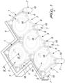
- the reference numeral 1 designates an infilling element for formwork 2 for the building sector, having a dome-like shape so as to form arc-like openings 3 which can be arranged between the perimetric walls 4 that delimit the crawl space 5.
- the formwork 2 has legs 6 supported by tubular elements 7 which are arranged vertically on the ground.
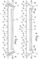
- the infilling element 1 has a flat base 8 that is longer than the dimension of the base diameter of the opening 3 (i.e., greater than the measurement between the free lower ends of the opening 3), the longitudinal ends 9a, 9b of which are substantially shaped complementarily to the lateral surface 10 of the tubular element 7.
- each one of said tubular elements 7 there are means for temporary engagement with the upper end of each one of said tubular elements 7, such means being constituted by a fork 11 which is shaped like an inverted letter C, between the wings 12a, 12b of which it is possible to insert said upper end of each one of said tubular elements 7.
- a wing 14 of chosen height protrudes at the outer longitudinal edge 13 of the base 8 along the entire length and in the direction of said tubular element 7.
- a first tab 15 protrudes longitudinally, on the opposite side with respect to said wing 14, proximate to the longitudinal ends 9a, 9b of the flat base 8, has a curved shape that is substantially complementary to the opening 3 and is provided with a first upper perimetric edge 16 provided with a lip 17 for engaging the second perimetric edge 18 of the opening 3 which is advantageously shaped like a letter C directed upward.
- connection of the infilling element 1 to the formwork 2 occurs by superimposing the first perimetric edge 16 on the outermost wing 19 of the second perimetric edge 18.
- protrusions 20a, 20b, 20c, 20d for connection between the flat base 8 and the ends of the first tab 15 that begin to protrude from it proximate to the longitudinal ends 9a, 9b.
- the infilling element 1 is furthermore provided with a plurality of second tabs 21, which are substantially mutually identical and protrude from the outer longitudinal edge 13 of the base 8 on the opposite side with respect to said wing 14.
- the plurality of second tabs 21 has such an inclination that their upper third perimetric edge 22 protrudes in the opposite direction with respect to the first tab 15, so as to achieve the function of a gasket in case of resting contact of the infilling element 1 against said walls 4, given the possibility of each one of the second tabs 21 to adapt to the not always flat shape of the part of said wall 4 against which it is rested.
- the plurality of second tabs 21 protrudes beyond the longitudinal ends 9a, 9b of the flat base 8.
- each one of the longitudinal ends 9a, 9b of the flat base 8 there is furthermore a pre-cut 23 which connects the outer longitudinal edge 13 of the flat base 8 to the wing 12b of the fork 11.
- the pre-cuts 23 are arranged with such an inclination as to produce, in case of breakage thereof, a decrease in the radius of curvature of the longitudinal ends 9a, 9b.
- the invention allows, during the laying of disposable formwork which rests on tubular elements which are arranged vertically on the ground, to obtain an excellent engagement and at the same time allow optimum and easy filling of the tube by means of the concrete, preventing at the same time said concrete from passing between the formwork and the perimetric wall that delimits the casting area.
- the invention allows furthermore, during the laying of disposable formwork, to achieve an optimum closure to the passage of concrete, absorbing any differences in length of said invention due to the use of recycled plastic material, which does not always have the same uniform shrinkage, absorbing at the same time any irregularities and protrusions usually present on the wall against which the tubular support will be arranged.
- the invention also allows to obtain an optimum closure, in the series arrangement, between said infilling elements and allows the user, during the laying of disposable formwork, to be adapted rapidly and easily if a closure of a protruding corner toward the flooring through 270 degrees is observed.
Landscapes
- Engineering & Computer Science (AREA)
- Architecture (AREA)
- Civil Engineering (AREA)
- Structural Engineering (AREA)
- Physics & Mathematics (AREA)
- Electromagnetism (AREA)
- Forms Removed On Construction Sites Or Auxiliary Members Thereof (AREA)
- Catalysts (AREA)
Claims (9)
- Élément de remplissage (1) pour coffrage (2) dans le secteur de la construction, ayant une forme de type dôme de sorte à former des ouvertures de type arc (3) qui peuvent être agencées entre les parois périmétriques (4) qui délimitent le vide sanitaire (5) et des pieds (6) supportés par des éléments tubulaires (7) qui sont agencés verticalement sur le sol, ledit élément de remplissage (1) ayant une base plate (8) à proximité des extrémités longitudinales (9a, 9b) desquelles font saillie vers le haut une première languette (15), qui a une forme complémentaire de ladite ouverture (3) et est pourvue d'une lèvre (17) pour mettre en prise le premier bord périmétrique (16) de ladite ouverture (3), et au moins une seconde languette (21), qui sert de garniture en cas de repos contre lesdites parois (4), lesdites extrémités longitudinales (9a, 9b) de ladite base plate (8) ayant une forme de type arc,
caractérisé en ce que ladite base plate (8) est plus longue que la dimension du diamètre de base de ladite ouverture (3), les extrémités longitudinales (9a, 9b) de celle-ci ayant une forme complémentaire de la surface latérale (10) dudit élément tubulaire (7), au niveau desdites extrémités longitudinales (9a, 9b) où se trouvent des moyens pour une mise en prise temporaire avec l'extrémité supérieure de chacun desdits éléments tubulaires (7), lesdits moyens étant constitués d'une fourche (11) qui a la forme d'une lettre C inversée entre les ailettes (12a, 12b) de laquelle il est possible d'insérer ladite extrémité supérieure de chacun desdits éléments tubulaires (7). - Élément de remplissage selon la revendication 1, caractérisé en ce qu'une ailette (14) de hauteur choisie fait saillie au niveau du bord longitudinal externe (13) de ladite base plate (8) tout au long de la longueur et dans la direction dudit élément tubulaire (7).
- Élément de remplissage selon la revendication 2, caractérisé en ce que la première languette (15) fait saillie longitudinalement, sur le côté opposé par rapport à ladite ailette (14), à proximité desdites extrémités longitudinales (9a, 9b) de ladite base plate (8) et a une forme incurvée qui est sensiblement complémentaire de ladite ouverture (3) et est pourvue d'un premier bord périmétrique supérieur (16) pourvu de la lèvre (17) pour mettre en prise le deuxième bord périmétrique (18) de ladite ouverture (3) et a la forme d'une lettre C dirigée vers le haut.
- Élément de remplissage selon une ou plusieurs des revendications précédentes, caractérisé en ce que sa liaison audit coffrage (2) se produit en superposant ledit premier bord périmétrique (16) sur une ailette la plus à l'extérieur (19) dudit deuxième bord périmétrique (18).
- Élément de remplissage selon une ou plusieurs des revendications précédentes, caractérisé en ce qu'il existe deux paires de saillies (20a, 20b, 20c, 20d) permettant la liaison entre ladite base plate (8) et les extrémités de ladite première languette (15) qui commencent à faire saillie à partir de celle-ci à proximité desdites extrémités longitudinales (9a, 9b).
- Élément de remplissage selon une ou plusieurs des revendications précédentes, caractérisé en ce qu'il a une pluralité de secondes languettes (21) qui sont sensiblement mutuellement identiques et font saillie à partir dudit bord longitudinal externe (13) de ladite base (8) sur le côté opposé par rapport à ladite ailette (14).
- Élément de remplissage selon la revendication 6, caractérisé en ce que ladite pluralité de secondes languettes (21) ont une inclinaison telle que leur troisième bord périmétrique supérieur (22) fait saillie dans la direction opposée par rapport à ladite première languette (15) de sorte à remplir la fonction d'une garniture dans le cas de contact de repos dudit élément de remplissage (1) contre lesdites parois (4) étant donné la possibilité de chacune desdites secondes languettes (21) de s'adapter à la forme de la partie de ladite paroi (4) contre laquelle elle repose.
- Élément de remplissage selon la revendication 6 ou 7, caractérisé en ce que ladite pluralité de secondes languettes (21) fait saillie au-delà desdites extrémités longitudinales (9a, 9b) de ladite base plate (8).
- Élément de remplissage selon une ou plusieurs des revendications précédentes, caractérisé en ce qu'à chacune desdites extrémités longitudinales (9a, 9b) de ladite base plate (8), se trouve une prédécoupe (23) qui relie ledit bord longitudinal externe (13) de ladite base plate (8) à ladite ailette (12b) de ladite fourche (11), lesdites prédécoupes (23) sont agencées avec une inclinaison de nature à produire, dans le cas de rupture de celui-ci, une diminution du rayon de courbure desdites extrémités longitudinales (9a, 9b).
Applications Claiming Priority (1)
| Application Number | Priority Date | Filing Date | Title |
|---|---|---|---|
| IT102019000011574A IT201900011574A1 (it) | 2019-07-12 | 2019-07-12 | Elemento di tamponamento per casseri per l’edilizia |
Publications (3)
| Publication Number | Publication Date |
|---|---|
| EP3763894A1 EP3763894A1 (fr) | 2021-01-13 |
| EP3763894B1 true EP3763894B1 (fr) | 2023-07-26 |
| EP3763894C0 EP3763894C0 (fr) | 2023-07-26 |
Family
ID=68582156
Family Applications (1)
| Application Number | Title | Priority Date | Filing Date |
|---|---|---|---|
| EP20182066.9A Active EP3763894B1 (fr) | 2019-07-12 | 2020-06-24 | Élément de matériau de remplissage pour coffrage dans le secteur de la construction |
Country Status (4)
| Country | Link |
|---|---|
| EP (1) | EP3763894B1 (fr) |
| ES (1) | ES2960715T3 (fr) |
| IT (1) | IT201900011574A1 (fr) |
| MA (1) | MA53880A (fr) |
Family Cites Families (6)
| Publication number | Priority date | Publication date | Assignee | Title |
|---|---|---|---|---|
| US2602323A (en) | 1949-05-02 | 1952-07-08 | Johannes C Leemhuis | Floor structure |
| IT1310542B1 (it) * | 1999-03-03 | 2002-02-18 | Valerio Pontarolo | Elemento modulare per vespaio e solaio |
| IT248146Y1 (it) | 1999-10-12 | 2002-12-10 | Daliform S R L | Cassero perfezionato per la costruzione di pavimenti, solai o simili |
| IT1315093B1 (it) | 2000-05-16 | 2003-02-03 | Valerio Pontarolo | Accessorio per elementi modulari di supporto ed aerazione per vespai,solai, pavimenti o simili manufatti edili |
| WO2015138427A1 (fr) * | 2014-03-12 | 2015-09-17 | Miskovich Joseph S | Unité de conduit de construction modulaire |
| IT201700020417A1 (it) * | 2017-02-23 | 2017-05-23 | Pontarolo Eng Spa | Struttura modulare di supporto per pavimenti. |
-
2019
- 2019-07-12 IT IT102019000011574A patent/IT201900011574A1/it unknown
-
2020
- 2020-06-24 ES ES20182066T patent/ES2960715T3/es active Active
- 2020-06-24 MA MA053880A patent/MA53880A/fr unknown
- 2020-06-24 EP EP20182066.9A patent/EP3763894B1/fr active Active
Also Published As
| Publication number | Publication date |
|---|---|
| ES2960715T3 (es) | 2024-03-06 |
| MA53880A (fr) | 2021-08-18 |
| EP3763894C0 (fr) | 2023-07-26 |
| EP3763894A1 (fr) | 2021-01-13 |
| IT201900011574A1 (it) | 2021-01-12 |
Similar Documents
| Publication | Publication Date | Title |
|---|---|---|
| US8770890B2 (en) | Module and assembly for managing the flow of water | |
| US10584487B2 (en) | Modular system for assembling a transpiring, disposable heat-insulation shuttering mould / formwork used for surface casting | |
| US8689507B2 (en) | Waterproofing system for a basement or similar structure | |
| EP1611302B1 (fr) | Modele de construction de piscine modulaire | |
| EP3763894B1 (fr) | Élément de matériau de remplissage pour coffrage dans le secteur de la construction | |
| WO2016077890A1 (fr) | Élément de construction | |
| US11879246B2 (en) | Module and method for managing water and other fluids | |
| US2948993A (en) | Drain construction for walls | |
| ITMI20130607A1 (it) | Cassero a perdere per la realizzazione di vespai aerati e vespaio aerato comprendente tale cassero | |
| AU2019101738B4 (en) | A void forming module and system therefor | |
| US8517712B2 (en) | Adjustable mold and associated method for making a drainage channel | |
| TWI541408B (zh) | 透水鋪面強化裝置 | |
| EP1972735B1 (fr) | Système d'éléments de plancher et procédé pour la fabrication d'éléments de plancher, et procédé pour la fabrication d'une construction de plancher utilisant les éléments de plancher | |
| KR102851197B1 (ko) | 배수성이 향상된 역류방지형 여와 | |
| EP4650542A1 (fr) | Dispositif pour l'obtention de plaques sanitaires ventilées thermiquement isolées | |
| US20260049488A1 (en) | System for Forming Ventilated Crawl Spaces or Interspaces or Elevated Platforms Composed by Dome-Shaped Formwork Elements Supported on Supporting Tubes Resting on a Foundation or on a Surface | |
| AU2018204382B2 (en) | Building Components | |
| GB2385071A (en) | Building foundation with insulating members | |
| KR20250025825A (ko) | 이중구조와 다공성재질의 수분저장용컵이 특징인 조경용 배수판 제조방법 | |
| AU2005240674A1 (en) | Cavity former | |
| IT202100010508A1 (it) | Sistema di elementi modulari per la realizzazione di solai nervati sopraelevati e/o aerati | |
| IT201800009303A1 (it) | Dispositivo per l’edilizia | |
| AU3397999A (en) | Slab beam footing formwork | |
| WO2003046307A1 (fr) | Element modulaire et procede pour isoler et ventiler un toit | |
| NZ715336A (en) | Mould |
Legal Events
| Date | Code | Title | Description |
|---|---|---|---|
| PUAI | Public reference made under article 153(3) epc to a published international application that has entered the european phase |
Free format text: ORIGINAL CODE: 0009012 |
|
| STAA | Information on the status of an ep patent application or granted ep patent |
Free format text: STATUS: THE APPLICATION HAS BEEN PUBLISHED |
|
| AK | Designated contracting states |
Kind code of ref document: A1 Designated state(s): AL AT BE BG CH CY CZ DE DK EE ES FI FR GB GR HR HU IE IS IT LI LT LU LV MC MK MT NL NO PL PT RO RS SE SI SK SM TR |
|
| AX | Request for extension of the european patent |
Extension state: BA ME |
|
| STAA | Information on the status of an ep patent application or granted ep patent |
Free format text: STATUS: REQUEST FOR EXAMINATION WAS MADE |
|
| 17P | Request for examination filed |
Effective date: 20210712 |
|
| RAV | Requested validation state of the european patent: fee paid |
Extension state: MA Effective date: 20210712 Extension state: TN Effective date: 20210712 |
|
| RAX | Requested extension states of the european patent have changed |
Extension state: BA Payment date: 20210712 Extension state: ME Payment date: 20210712 |
|
| RBV | Designated contracting states (corrected) |
Designated state(s): AL AT BE BG CH CY CZ DE DK EE ES FI FR GB GR HR HU IE IS IT LI LT LU LV MC MK MT NL NO PL PT RO RS SE SI SK SM TR |
|
| RIC1 | Information provided on ipc code assigned before grant |
Ipc: E04F 15/12 20060101ALI20230119BHEP Ipc: E04B 5/48 20060101ALI20230119BHEP Ipc: E04B 5/36 20060101ALI20230119BHEP Ipc: E04B 5/32 20060101AFI20230119BHEP |
|
| GRAP | Despatch of communication of intention to grant a patent |
Free format text: ORIGINAL CODE: EPIDOSNIGR1 |
|
| STAA | Information on the status of an ep patent application or granted ep patent |
Free format text: STATUS: GRANT OF PATENT IS INTENDED |
|
| INTG | Intention to grant announced |
Effective date: 20230306 |
|
| RIN1 | Information on inventor provided before grant (corrected) |
Inventor name: SERAFIN, ANTONIO Inventor name: SERAFIN, GIOVANNI Inventor name: ALBERTINI, ANTIMO RICCARDO |
|
| GRAS | Grant fee paid |
Free format text: ORIGINAL CODE: EPIDOSNIGR3 |
|
| GRAA | (expected) grant |
Free format text: ORIGINAL CODE: 0009210 |
|
| STAA | Information on the status of an ep patent application or granted ep patent |
Free format text: STATUS: THE PATENT HAS BEEN GRANTED |
|
| AK | Designated contracting states |
Kind code of ref document: B1 Designated state(s): AL AT BE BG CH CY CZ DE DK EE ES FI FR GB GR HR HU IE IS IT LI LT LU LV MC MK MT NL NO PL PT RO RS SE SI SK SM TR |
|
| REG | Reference to a national code |
Ref country code: CH Ref legal event code: EP |
|
| REG | Reference to a national code |
Ref country code: IE Ref legal event code: FG4D |
|
| REG | Reference to a national code |
Ref country code: DE Ref legal event code: R096 Ref document number: 602020014325 Country of ref document: DE |
|
| U01 | Request for unitary effect filed |
Effective date: 20230823 |
|
| U07 | Unitary effect registered |
Designated state(s): AT BE BG DE DK EE FI FR IT LT LU LV MT NL PT SE SI Effective date: 20230831 |
|
| REG | Reference to a national code |
Ref country code: LT Ref legal event code: MG9D |
|
| PG25 | Lapsed in a contracting state [announced via postgrant information from national office to epo] |
Ref country code: GR Free format text: LAPSE BECAUSE OF FAILURE TO SUBMIT A TRANSLATION OF THE DESCRIPTION OR TO PAY THE FEE WITHIN THE PRESCRIBED TIME-LIMIT Effective date: 20231027 |
|
| PG25 | Lapsed in a contracting state [announced via postgrant information from national office to epo] |
Ref country code: IS Free format text: LAPSE BECAUSE OF FAILURE TO SUBMIT A TRANSLATION OF THE DESCRIPTION OR TO PAY THE FEE WITHIN THE PRESCRIBED TIME-LIMIT Effective date: 20231126 |
|
| PG25 | Lapsed in a contracting state [announced via postgrant information from national office to epo] |
Ref country code: RS Free format text: LAPSE BECAUSE OF FAILURE TO SUBMIT A TRANSLATION OF THE DESCRIPTION OR TO PAY THE FEE WITHIN THE PRESCRIBED TIME-LIMIT Effective date: 20230726 Ref country code: NO Free format text: LAPSE BECAUSE OF FAILURE TO SUBMIT A TRANSLATION OF THE DESCRIPTION OR TO PAY THE FEE WITHIN THE PRESCRIBED TIME-LIMIT Effective date: 20231026 Ref country code: IS Free format text: LAPSE BECAUSE OF FAILURE TO SUBMIT A TRANSLATION OF THE DESCRIPTION OR TO PAY THE FEE WITHIN THE PRESCRIBED TIME-LIMIT Effective date: 20231126 Ref country code: HR Free format text: LAPSE BECAUSE OF FAILURE TO SUBMIT A TRANSLATION OF THE DESCRIPTION OR TO PAY THE FEE WITHIN THE PRESCRIBED TIME-LIMIT Effective date: 20230726 Ref country code: GR Free format text: LAPSE BECAUSE OF FAILURE TO SUBMIT A TRANSLATION OF THE DESCRIPTION OR TO PAY THE FEE WITHIN THE PRESCRIBED TIME-LIMIT Effective date: 20231027 |
|
| PG25 | Lapsed in a contracting state [announced via postgrant information from national office to epo] |
Ref country code: PL Free format text: LAPSE BECAUSE OF FAILURE TO SUBMIT A TRANSLATION OF THE DESCRIPTION OR TO PAY THE FEE WITHIN THE PRESCRIBED TIME-LIMIT Effective date: 20230726 |
|
| REG | Reference to a national code |
Ref country code: ES Ref legal event code: FG2A Ref document number: 2960715 Country of ref document: ES Kind code of ref document: T3 Effective date: 20240306 |
|
| REG | Reference to a national code |
Ref country code: DE Ref legal event code: R097 Ref document number: 602020014325 Country of ref document: DE |
|
| PG25 | Lapsed in a contracting state [announced via postgrant information from national office to epo] |
Ref country code: SM Free format text: LAPSE BECAUSE OF FAILURE TO SUBMIT A TRANSLATION OF THE DESCRIPTION OR TO PAY THE FEE WITHIN THE PRESCRIBED TIME-LIMIT Effective date: 20230726 Ref country code: RO Free format text: LAPSE BECAUSE OF FAILURE TO SUBMIT A TRANSLATION OF THE DESCRIPTION OR TO PAY THE FEE WITHIN THE PRESCRIBED TIME-LIMIT Effective date: 20230726 Ref country code: CZ Free format text: LAPSE BECAUSE OF FAILURE TO SUBMIT A TRANSLATION OF THE DESCRIPTION OR TO PAY THE FEE WITHIN THE PRESCRIBED TIME-LIMIT Effective date: 20230726 Ref country code: SK Free format text: LAPSE BECAUSE OF FAILURE TO SUBMIT A TRANSLATION OF THE DESCRIPTION OR TO PAY THE FEE WITHIN THE PRESCRIBED TIME-LIMIT Effective date: 20230726 |
|
| PLBE | No opposition filed within time limit |
Free format text: ORIGINAL CODE: 0009261 |
|
| STAA | Information on the status of an ep patent application or granted ep patent |
Free format text: STATUS: NO OPPOSITION FILED WITHIN TIME LIMIT |
|
| 26N | No opposition filed |
Effective date: 20240429 |
|
| U20 | Renewal fee for the european patent with unitary effect paid |
Year of fee payment: 5 Effective date: 20240620 |
|
| PG25 | Lapsed in a contracting state [announced via postgrant information from national office to epo] |
Ref country code: MC Free format text: LAPSE BECAUSE OF FAILURE TO SUBMIT A TRANSLATION OF THE DESCRIPTION OR TO PAY THE FEE WITHIN THE PRESCRIBED TIME-LIMIT Effective date: 20230726 |
|
| REG | Reference to a national code |
Ref country code: CH Ref legal event code: PL |
|
| GBPC | Gb: european patent ceased through non-payment of renewal fee |
Effective date: 20240624 |
|
| PG25 | Lapsed in a contracting state [announced via postgrant information from national office to epo] |
Ref country code: IE Free format text: LAPSE BECAUSE OF NON-PAYMENT OF DUE FEES Effective date: 20240624 |
|
| PG25 | Lapsed in a contracting state [announced via postgrant information from national office to epo] |
Ref country code: CH Free format text: LAPSE BECAUSE OF NON-PAYMENT OF DUE FEES Effective date: 20240630 |
|
| PG25 | Lapsed in a contracting state [announced via postgrant information from national office to epo] |
Ref country code: GB Free format text: LAPSE BECAUSE OF NON-PAYMENT OF DUE FEES Effective date: 20240624 |
|
| U20 | Renewal fee for the european patent with unitary effect paid |
Year of fee payment: 6 Effective date: 20250620 |
|
| PGFP | Annual fee paid to national office [announced via postgrant information from national office to epo] |
Ref country code: ES Payment date: 20250707 Year of fee payment: 6 |
|
| VS25 | Lapsed in a validation state [announced via postgrant information from nat. office to epo] |
Ref country code: MA Free format text: FAILURE TO ELECT DOMICILE IN THE NATIONAL COUNTRY Effective date: 20231027 |
|
| PG25 | Lapsed in a contracting state [announced via postgrant information from national office to epo] |
Ref country code: CY Free format text: LAPSE BECAUSE OF FAILURE TO SUBMIT A TRANSLATION OF THE DESCRIPTION OR TO PAY THE FEE WITHIN THE PRESCRIBED TIME-LIMIT; INVALID AB INITIO Effective date: 20200624 |
|
| PG25 | Lapsed in a contracting state [announced via postgrant information from national office to epo] |
Ref country code: HU Free format text: LAPSE BECAUSE OF FAILURE TO SUBMIT A TRANSLATION OF THE DESCRIPTION OR TO PAY THE FEE WITHIN THE PRESCRIBED TIME-LIMIT; INVALID AB INITIO Effective date: 20200624 |