EP3763938B1 - Verfahren zur verbindung von zwei windturbinenschaufelteilen, verfahren zur herstellung einer windturbine und verfahren zum verbinden von zwei formteilen - Google Patents
Verfahren zur verbindung von zwei windturbinenschaufelteilen, verfahren zur herstellung einer windturbine und verfahren zum verbinden von zwei formteilen Download PDFInfo
- Publication number
- EP3763938B1 EP3763938B1 EP19185181.5A EP19185181A EP3763938B1 EP 3763938 B1 EP3763938 B1 EP 3763938B1 EP 19185181 A EP19185181 A EP 19185181A EP 3763938 B1 EP3763938 B1 EP 3763938B1
- Authority
- EP
- European Patent Office
- Prior art keywords
- wind turbine
- markers
- turbine blade
- blade portion
- blade
- Prior art date
- Legal status (The legal status is an assumption and is not a legal conclusion. Google has not performed a legal analysis and makes no representation as to the accuracy of the status listed.)
- Active
Links
Images


Classifications
-
- F—MECHANICAL ENGINEERING; LIGHTING; HEATING; WEAPONS; BLASTING
- F03—MACHINES OR ENGINES FOR LIQUIDS; WIND, SPRING, OR WEIGHT MOTORS; PRODUCING MECHANICAL POWER OR A REACTIVE PROPULSIVE THRUST, NOT OTHERWISE PROVIDED FOR
- F03D—WIND MOTORS
- F03D13/00—Assembly, mounting or commissioning of wind motors; Arrangements specially adapted for transporting wind motor components
- F03D13/10—Assembly of wind motors; Arrangements for erecting wind motors
-
- F—MECHANICAL ENGINEERING; LIGHTING; HEATING; WEAPONS; BLASTING
- F03—MACHINES OR ENGINES FOR LIQUIDS; WIND, SPRING, OR WEIGHT MOTORS; PRODUCING MECHANICAL POWER OR A REACTIVE PROPULSIVE THRUST, NOT OTHERWISE PROVIDED FOR
- F03D—WIND MOTORS
- F03D1/00—Wind motors with rotation axis substantially parallel to the air flow entering the rotor
- F03D1/06—Rotors
- F03D1/0608—Rotors characterised by their aerodynamic shape
- F03D1/0633—Rotors characterised by their aerodynamic shape of the blades
-
- B—PERFORMING OPERATIONS; TRANSPORTING
- B22—CASTING; POWDER METALLURGY
- B22C—FOUNDRY MOULDING
- B22C9/00—Moulds or cores; Moulding processes
- B22C9/06—Permanent moulds for shaped castings
-
- B—PERFORMING OPERATIONS; TRANSPORTING
- B29—WORKING OF PLASTICS; WORKING OF SUBSTANCES IN A PLASTIC STATE IN GENERAL
- B29C—SHAPING OR JOINING OF PLASTICS; SHAPING OF MATERIAL IN A PLASTIC STATE, NOT OTHERWISE PROVIDED FOR; AFTER-TREATMENT OF THE SHAPED PRODUCTS, e.g. REPAIRING
- B29C65/00—Joining or sealing of preformed parts, e.g. welding of plastics materials; Apparatus therefor
- B29C65/78—Means for handling the parts to be joined, e.g. for making containers or hollow articles, e.g. means for handling sheets, plates, web-like materials, tubular articles, hollow articles or elements to be joined therewith; Means for discharging the joined articles from the joining apparatus
- B29C65/7802—Positioning the parts to be joined, e.g. aligning, indexing or centring
- B29C65/7805—Positioning the parts to be joined, e.g. aligning, indexing or centring the parts to be joined comprising positioning features
- B29C65/7817—Positioning the parts to be joined, e.g. aligning, indexing or centring the parts to be joined comprising positioning features in the form of positioning marks
-
- B—PERFORMING OPERATIONS; TRANSPORTING
- B29—WORKING OF PLASTICS; WORKING OF SUBSTANCES IN A PLASTIC STATE IN GENERAL
- B29C—SHAPING OR JOINING OF PLASTICS; SHAPING OF MATERIAL IN A PLASTIC STATE, NOT OTHERWISE PROVIDED FOR; AFTER-TREATMENT OF THE SHAPED PRODUCTS, e.g. REPAIRING
- B29C66/00—General aspects of processes or apparatus for joining preformed parts
- B29C66/01—General aspects dealing with the joint area or with the area to be joined
- B29C66/05—Particular design of joint configurations
- B29C66/10—Particular design of joint configurations particular design of the joint cross-sections
- B29C66/11—Joint cross-sections comprising a single joint-segment, i.e. one of the parts to be joined comprising a single joint-segment in the joint cross-section
- B29C66/114—Single butt joints
- B29C66/1142—Single butt to butt joints
-
- B—PERFORMING OPERATIONS; TRANSPORTING
- B29—WORKING OF PLASTICS; WORKING OF SUBSTANCES IN A PLASTIC STATE IN GENERAL
- B29C—SHAPING OR JOINING OF PLASTICS; SHAPING OF MATERIAL IN A PLASTIC STATE, NOT OTHERWISE PROVIDED FOR; AFTER-TREATMENT OF THE SHAPED PRODUCTS, e.g. REPAIRING
- B29C66/00—General aspects of processes or apparatus for joining preformed parts
- B29C66/50—General aspects of joining tubular articles; General aspects of joining long products, i.e. bars or profiled elements; General aspects of joining single elements to tubular articles, hollow articles or bars; General aspects of joining several hollow-preforms to form hollow or tubular articles
- B29C66/51—Joining tubular articles, profiled elements or bars; Joining single elements to tubular articles, hollow articles or bars; Joining several hollow-preforms to form hollow or tubular articles
- B29C66/54—Joining several hollow-preforms, e.g. half-shells, to form hollow articles, e.g. for making balls, containers; Joining several hollow-preforms, e.g. half-cylinders, to form tubular articles
-
- B—PERFORMING OPERATIONS; TRANSPORTING
- B29—WORKING OF PLASTICS; WORKING OF SUBSTANCES IN A PLASTIC STATE IN GENERAL
- B29C—SHAPING OR JOINING OF PLASTICS; SHAPING OF MATERIAL IN A PLASTIC STATE, NOT OTHERWISE PROVIDED FOR; AFTER-TREATMENT OF THE SHAPED PRODUCTS, e.g. REPAIRING
- B29C66/00—General aspects of processes or apparatus for joining preformed parts
- B29C66/90—Measuring or controlling the joining process
- B29C66/98—Determining the joining area by using markings on at least one of the parts to be joined
-
- B—PERFORMING OPERATIONS; TRANSPORTING
- B29—WORKING OF PLASTICS; WORKING OF SUBSTANCES IN A PLASTIC STATE IN GENERAL
- B29D—PRODUCING PARTICULAR ARTICLES FROM PLASTICS OR FROM SUBSTANCES IN A PLASTIC STATE
- B29D99/00—Subject matter not provided for in other groups of this subclass
- B29D99/0025—Producing blades or the like, e.g. blades for turbines, propellers, or wings
- B29D99/0028—Producing blades or the like, e.g. blades for turbines, propellers, or wings hollow blades
-
- F—MECHANICAL ENGINEERING; LIGHTING; HEATING; WEAPONS; BLASTING
- F03—MACHINES OR ENGINES FOR LIQUIDS; WIND, SPRING, OR WEIGHT MOTORS; PRODUCING MECHANICAL POWER OR A REACTIVE PROPULSIVE THRUST, NOT OTHERWISE PROVIDED FOR
- F03D—WIND MOTORS
- F03D1/00—Wind motors with rotation axis substantially parallel to the air flow entering the rotor
- F03D1/06—Rotors
- F03D1/065—Rotors characterised by their construction elements
- F03D1/0675—Rotors characterised by their construction elements of the blades
- F03D1/0677—Longitudinally segmented blades; Connectors therefor
-
- F—MECHANICAL ENGINEERING; LIGHTING; HEATING; WEAPONS; BLASTING
- F03—MACHINES OR ENGINES FOR LIQUIDS; WIND, SPRING, OR WEIGHT MOTORS; PRODUCING MECHANICAL POWER OR A REACTIVE PROPULSIVE THRUST, NOT OTHERWISE PROVIDED FOR
- F03D—WIND MOTORS
- F03D9/00—Adaptations of wind motors for special use; Combinations of wind motors with apparatus driven thereby; Wind motors specially adapted for installation in particular locations
- F03D9/20—Wind motors characterised by the driven apparatus
- F03D9/25—Wind motors characterised by the driven apparatus the apparatus being an electrical generator
-
- B—PERFORMING OPERATIONS; TRANSPORTING
- B29—WORKING OF PLASTICS; WORKING OF SUBSTANCES IN A PLASTIC STATE IN GENERAL
- B29K—INDEXING SCHEME ASSOCIATED WITH SUBCLASSES B29B, B29C OR B29D, RELATING TO MOULDING MATERIALS OR TO MATERIALS FOR MOULDS, REINFORCEMENTS, FILLERS OR PREFORMED PARTS, e.g. INSERTS
- B29K2105/00—Condition, form or state of moulded material or of the material to be shaped
- B29K2105/06—Condition, form or state of moulded material or of the material to be shaped containing reinforcements, fillers or inserts
- B29K2105/08—Condition, form or state of moulded material or of the material to be shaped containing reinforcements, fillers or inserts of continuous length, e.g. cords, rovings, mats, fabrics, strands or yarns
-
- B—PERFORMING OPERATIONS; TRANSPORTING
- B29—WORKING OF PLASTICS; WORKING OF SUBSTANCES IN A PLASTIC STATE IN GENERAL
- B29K—INDEXING SCHEME ASSOCIATED WITH SUBCLASSES B29B, B29C OR B29D, RELATING TO MOULDING MATERIALS OR TO MATERIALS FOR MOULDS, REINFORCEMENTS, FILLERS OR PREFORMED PARTS, e.g. INSERTS
- B29K2307/00—Use of elements other than metals as reinforcement
- B29K2307/04—Carbon
-
- B—PERFORMING OPERATIONS; TRANSPORTING
- B29—WORKING OF PLASTICS; WORKING OF SUBSTANCES IN A PLASTIC STATE IN GENERAL
- B29K—INDEXING SCHEME ASSOCIATED WITH SUBCLASSES B29B, B29C OR B29D, RELATING TO MOULDING MATERIALS OR TO MATERIALS FOR MOULDS, REINFORCEMENTS, FILLERS OR PREFORMED PARTS, e.g. INSERTS
- B29K2309/00—Use of inorganic materials not provided for in groups B29K2303/00 - B29K2307/00, as reinforcement
- B29K2309/08—Glass
-
- B—PERFORMING OPERATIONS; TRANSPORTING
- B29—WORKING OF PLASTICS; WORKING OF SUBSTANCES IN A PLASTIC STATE IN GENERAL
- B29L—INDEXING SCHEME ASSOCIATED WITH SUBCLASS B29C, RELATING TO PARTICULAR ARTICLES
- B29L2031/00—Other particular articles
- B29L2031/08—Blades for rotors, stators, fans, turbines or the like, e.g. screw propellers
- B29L2031/082—Blades, e.g. for helicopters
- B29L2031/085—Wind turbine blades
-
- F—MECHANICAL ENGINEERING; LIGHTING; HEATING; WEAPONS; BLASTING
- F05—INDEXING SCHEMES RELATING TO ENGINES OR PUMPS IN VARIOUS SUBCLASSES OF CLASSES F01-F04
- F05B—INDEXING SCHEME RELATING TO WIND, SPRING, WEIGHT, INERTIA OR LIKE MOTORS, TO MACHINES OR ENGINES FOR LIQUIDS COVERED BY SUBCLASSES F03B, F03D AND F03G
- F05B2230/00—Manufacture
- F05B2230/60—Assembly methods
- F05B2230/604—Assembly methods using positioning or alignment devices for aligning or centering, e.g. pins
-
- F—MECHANICAL ENGINEERING; LIGHTING; HEATING; WEAPONS; BLASTING
- F05—INDEXING SCHEMES RELATING TO ENGINES OR PUMPS IN VARIOUS SUBCLASSES OF CLASSES F01-F04
- F05B—INDEXING SCHEME RELATING TO WIND, SPRING, WEIGHT, INERTIA OR LIKE MOTORS, TO MACHINES OR ENGINES FOR LIQUIDS COVERED BY SUBCLASSES F03B, F03D AND F03G
- F05B2240/00—Components
- F05B2240/20—Rotors
- F05B2240/30—Characteristics of rotor blades, i.e. of any element transforming dynamic fluid energy to or from rotational energy and being attached to a rotor
- F05B2240/302—Segmented or sectional blades
-
- Y—GENERAL TAGGING OF NEW TECHNOLOGICAL DEVELOPMENTS; GENERAL TAGGING OF CROSS-SECTIONAL TECHNOLOGIES SPANNING OVER SEVERAL SECTIONS OF THE IPC; TECHNICAL SUBJECTS COVERED BY FORMER USPC CROSS-REFERENCE ART COLLECTIONS [XRACs] AND DIGESTS
- Y02—TECHNOLOGIES OR APPLICATIONS FOR MITIGATION OR ADAPTATION AGAINST CLIMATE CHANGE
- Y02E—REDUCTION OF GREENHOUSE GAS [GHG] EMISSIONS, RELATED TO ENERGY GENERATION, TRANSMISSION OR DISTRIBUTION
- Y02E10/00—Energy generation through renewable energy sources
- Y02E10/70—Wind energy
- Y02E10/72—Wind turbines with rotation axis in wind direction
-
- Y—GENERAL TAGGING OF NEW TECHNOLOGICAL DEVELOPMENTS; GENERAL TAGGING OF CROSS-SECTIONAL TECHNOLOGIES SPANNING OVER SEVERAL SECTIONS OF THE IPC; TECHNICAL SUBJECTS COVERED BY FORMER USPC CROSS-REFERENCE ART COLLECTIONS [XRACs] AND DIGESTS
- Y02—TECHNOLOGIES OR APPLICATIONS FOR MITIGATION OR ADAPTATION AGAINST CLIMATE CHANGE
- Y02P—CLIMATE CHANGE MITIGATION TECHNOLOGIES IN THE PRODUCTION OR PROCESSING OF GOODS
- Y02P70/00—Climate change mitigation technologies in the production process for final industrial or consumer products
- Y02P70/50—Manufacturing or production processes characterised by the final manufactured product
Definitions
- the present invention relates to a method for connecting two wind turbine blade portions, a method for producing a wind turbine, and a method for connecting two molded portions.
- Modern wind turbine rotor blades are built from fiberreinforced plastics.
- a rotor blade typically comprises an airfoil having a rounded leading edge and a sharp trailing edge.
- the rotor blade is connected with its blade root to a hub of the wind turbine. Further, the rotor blade is connected to the hub by means of a pitch bearing that allows a pitch movement of the rotor blade. Long rotor blades experience high wind forces and are, thus, subjected to heavy loads.
- Rotor blades may be made of two half-shells connected to each other. As rotor blades become longer, it may be advantageous to manufacture a rotor blade divided into two or more segments along a longitudinal axis (i.e. longitudinal segments) of the blade. Such blade segments are also known as spanwise segments. Further, such spanwise segments may be casted individually and connected together after casting.
- EP 2 432 972 B1 shows a method for assembling spanwise segments of a wind turbine blade.
- WO 2018/215457 A1 discloses a method of assembling a wind turbine blade from wind turbine blade elements.
- the wind turbine elements are equipped with alignment means in form of lasers and optical sensors.
- the lasers are mounted on the first element, and the optical sensors are mounted on the second element.
- one blade element may be fixed while the other blade element is moved to achieve suitable alignment as required by the sensor system.
- US 2017/043542 A1 discloses a system and apparatus for the manufacture of a wind turbine blade where portions of a blade, preferably blade half shells, are formed in suitable molds, before transferring them to a post-molding station where post-molding operations can be performed.
- the blade shells are formed in the mold to have integrated flanges which facilitate easy handling of the blade shells during subsequent manufacturing operations.
- a blade cradle of a post-molding station to receive a wind turbine blade shell, where a lifting jack apparatus can be located within the blade cradle structure for the application of a lifting force to a surface of a blade shell received in the cradle, to facilitate access to all sections of the surface of the blade shell.
- a method for connecting two wind turbine blade portions comprises the steps of: a) providing a first wind turbine blade portion and a second wind turbine blade portion, b) providing a plurality of first markers on the first blade portion and providing a plurality of second markers on the second blade portion, c) determining of target positions of the first markers and the second markers, d) aligning the wind turbine blade portions to each other and comparing actual positions of the first markers and the second markers with the target positions, and e) connecting the wind turbine blade portions together.
- each blade portion comprises two blade shells arranged opposite and connected to each other.
- Providing markers on the blade portion means that the markers are set. Setting the markers may mean that physical markers are connected to the blade portion, created on the blade portion or digital markers are allocated to the blade portion. Aligning means that one of the blade portions or both are moved until the blade portions match as intended.
- the first blade portion comprises an outer surface at which the first markers are provided.
- the second blade portion comprises an outer surface at which the second markers are provided.
- the first markers and the second markers are arranged along a longitudinal direction of the blade.
- at least three, four, five, six, seven, eight, nine, ten or more first markers are provided in step b).
- at least three, four, five, six, seven, eight, nine, ten or more second markers are provided in step b).
- the wind turbine blade portions are side by side in longitudinal direction of the blade when aligned to each other.
- the first wind turbine blade portion is molded by means of a first mold and the second wind turbine blade portion is molded by means of a second mold.
- the first and the second blade portions are casted. Molding the blade by means of at least two molds has the advantage that longer blades may by manufactured.
- the first mold is a multi-part, in particular two-part, mold and/or the second mold is a multi-part, in particular two-part, mold. This has the advantage that the blade portions may be accessible after molding without removing the blade portion from the lower part of the mold which carries the mold.
- the first mold comprises a hollow space having a negative form of the first blade portion and/or the second mold comprises a hollow space having a negative form of the second blade portion.
- step b) is executed when the first wind turbine blade portion is in the first mold and/or the second wind turbine blade portion is in the second mold.
- step b) is executed during molding or afterwards.
- the first blade portion lies in the first mold and/or the second blade portion lies in the second mold when step b) is executed. Therefore, a large contact surface between the respective blade portion and the respective mold is provided.
- initial positions of the first and the second markers are determined during or immediately after step b).
- the initial positions are measured and recorded.
- an ideal shape of the blade portion may be reproduced even after handling or manipulating the same.
- the target positions of the markers are determined by means of the initial positions of the first and the second markers.
- the initial positions of the first markers relative to each other are set as target positions of the first markers.
- the initial positions of the second markers relative to each other are set as target positions of the second markers.
- the target positions of the first and the second markers are determined by setting a relation between the initial position of the first markers relative to the initial positions of the second markers.
- the target positions are determined by means of computer generated positions.
- the initial positions can be combined with computer generated positions of the markers for obtaining the target positions of the first and the second markers.
- the actual positions of the first and/or the second markers are detected by means of detecting means during step d).
- the detecting means comprise a sensor, in particular sensors, and/or a camera, in particular cameras.
- Step d) is executed by means of digital image correlation.
- Digital image correlation and tracking is an optical method that employs tracking and image registration techniques for accurate 2D and 3D measurements of changes in images. This method can be used to measure full-field displacement and strains. Compared to strain gages and extensometers, the amount of information gathered about the fine details of deformation during mechanical tests is increased due to the ability to provide e.g. both local and average data using digital image correlation. This has the advantage that a real time measurement and alignment can be executed.
- the carrying device may comprise a first support structure, in particular a first trolley or yoke, configured to support the first blade portion at one contact surface and a second support structure, in particular a second trolley or yoke, configured to support the first blade portion at another contact surface.
- first and the second support structures are configured to move in longitudinal direction of the blade relative to each other when supporting the first blade portion.
- the second blade portion is fixed.
- the carrying device is configured to move the first blade portion in longitudinal direction of the blade and/or in height direction and/or in a side direction which is perpendicular to the longitudinal direction.
- the carrying device is configured to rotate or tilt the first blade portion around the longitudinal direction and/or the height direction and/or the side direction.
- first and the second support structures comprise a lifting system for lifting the blade portion.
- first and the second support structures comprise a tilt system for tilting and/or twisting the blade portion.
- three, four, five, six or more support structures, in particular a trolleys or yokes, are provided for supporting the first blade portion.
- the carrying device is configured to move the second wind turbine blade portion in at least 3, 4, 5 or 6 degrees of freedom relative to the first wind turbine blade portion.
- the carrying device may comprise a third support structure, in particular a third trolley or yoke, configured to support the second blade portion at one contact surface and a fourth support structure, in particular a fourth trolley or yoke, configured to support the second blade portion at another contact surface.
- the third and the fourth support structures are configured to move in longitudinal direction of the blade relative to each other when supporting the second blade portion.
- the third and the fourth support structures comprise a lifting system for lifting the second blade portion.
- the third and the fourth support structures comprise a tilt system for tilting and/or twisting the second blade portion.
- three, four, five, six or more support structures, in particular trolleys or yokes, are provided for supporting the second blade portion.
- step d) and/or e) leading edges of the first and the second wind turbine blade portions face downward or upward.
- the first and the second markers are digitally generated points and/or concretely provided on the respective wind turbine blade portion.
- Digitally generated points have the advantage that setting such points can be executed e.g. automatically.
- markers i.e. physical markers
- markers have the advantage that such points may be visible without equipment.
- first wind turbine blade portion and the second wind turbine blade portion are longitudinal segments of the wind turbine blade.
- an angle between connecting surfaces of the wind turbine blade portions and a longitudinal axis of the wind turbine blade is at least 45°, in particular 90°.
- a method for producing a wind turbine comprises the steps of: a2) connecting two wind turbine blade portions according to such a method for connecting two wind turbine blade portions such that a wind turbine blade is provided, and b2) connecting the wind turbine blade to a hub of the wind turbine.
- the method comprises further the steps of providing a tower, a nacelle and a hub of the wind turbine.
- Wind turbine presently refers to an apparatus converting the wind's kinetic energy into rotational energy, which may again be converted to electrical energy by the apparatus.
- a method for connecting two molded portions comprises the steps of: a3) molding a first portion by means of a first mold and a second portion by means of a second mold, b3) providing first markers on the first portion when the first portion is in the first mold and second markers on the second portion when the second portion is in the second mold, and c3) connecting the first and the second portions together by means of the first and the second markers.
- first and the second portions are substantially stressless and, thus, undeformed when providing the markers. Therefore, a shape accuracy of two connected portions can be improved.
- the first and the second portion may be molded by means of casting.
- Providing the markers on the first portion means that the markers are set.
- the first portion lies in the first mold and/or the second portion lies in the second mold during step b3). Therefore, a large contact surface between the respective portion and the respective mold is provided.
- the first and the second portions are connected to form a component.
- the component e.g. may be a wind turbine blade or any other component.
- the first mold is a multi-part, in particular two-part, mold and/or the second mold is a multi-part, in particular two-part, mold.
- the first mold comprises a hollow space having a negative form of the first portion and/or the second mold comprises a hollow space having a negative form of the second portion.
- Fig. 1 shows a wind turbine 1.
- the wind turbine 1 comprises a rotor 2 connected to a generator (not shown) arranged inside a nacelle 3.
- the nacelle 3 is arranged at an upper end of a tower 4 of the wind turbine 1.
- the rotor 2 comprises three blades 5 (i.e. wind turbine blades).
- the blades 5 are connected to a hub 6 of the wind turbine 1.
- Rotors 2 of this kind may have diameters ranging from, for example, 30 to 300 meters or even more.
- the blades 5 are subjected to high wind loads.
- the blades 5 need to be lightweight.
- blades 5 in modern wind turbines 1 are manufactured from fiberreinforced composite materials, e.g. by means of casting. Oftentimes, glass or carbon fibers in the form of unidirectional fiber mats are used.
- Such blades 5 may also include woods and other reinforcement materials.
- Fig. 2 shows the blade 5.
- the blade 5 comprises an aerodynamically designed portion 7 which is shaped for optimum exploitation of the wind energy and a blade root 8 for connecting the blade 5 to the hub 6. Further, the blade 5 comprises a blade tip 9 which faces away from the blade root 8. The blade 5 extends in a longitudinal direction L which points from the blade root 8 towards the blade tip 9.
- the blade 5 has a length M which, for example, may be between 15 to 100 m or even more.
- the wind turbine blade 5 comprises a leading edge 10 and a trailing edge 11.
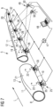
- Fig. 3 shows a perspective view of a blade portion 12 (also referred as first blade portion) and a blade portion 13 (also referred as second blade portion).
- the blade portion 12 comprises the blade tip 9 and the blade portion 13 comprises the blade root 8.
- the blade portion 12 comprises a connecting surface 23 and the blade portion 13 comprises a connecting surface 24.
- the blade portions 12, 13 are configured to be connected at together the connecting surfaces 23, 24.
- the connecting surfaces 23, 24 run essentially perpendicular to the longitudinal direction L.
- the blade portions 12, 13 are longitudinal segments of the blade 5 (see e.g. Fig. 2 ).
- the blade portion 12 is casted by means of a mold 14 (also referred as first mold) and the blade portion 13 is casted by means of a mold 15 (also referred as second mold).
- the mold 14 is a multi-part mold comprising a lower mold part 16 and an upper mold part (not shown).
- the upper mold part may be removed after molding the blade portion 12 as shown in Fig. 3 .
- the mold 15 is a multi-part mold comprising a lower mold part 17 and an upper mold part (not shown).
- the mold 14 comprises a hollow space 18 having a negative form of the blade portion 12.
- the mold 15 comprises a hollow space (not shown) having a negative form of the blade portion 13.
- an outer surface 19 of the blade portion 12 is exposed.
- Markers 20 also referred as first markers
- an outer surface 21 of the blade portion 13 is exposed.
- Markers 22 also referred as second markers
- the markers 20, 22 can be set when the blade portions 12, 13 lie in the molds 14, 15. Therefore, a large contact surface between the blade portions 12, 13 and the molds 14, 15 is provided. This has the advantage that the blade portions 12, 13 are substantially stressless and, thus, undeformed.
- initial positions of the markers 20, 22 may be determined, e.g. by means of measuring and recording the same. Further, target positions of the markers 20, 22 may be determined by setting a relation between the initial position of the markers 20 relative to the initial positions of the markers 22.
- the target positions are determined by means of computer generated positions.
- the initial positions can be combined with computer generated positions of the markers 20, 22 for obtaining the target positions of the markers 20, 22.
- the markers 20, 22 may be digitally generated points and/or concretely provided or created on the surface 19, 21.
- 2 - 30, 3 - 10, 3 - 7, or 4 to 5 markers 20 are provided.
- 2 - 30, 3 - 10, 3 - 7, or 4 to 5 markers 22 are provided.
- the markers 20 and/or the markers 22 may be arranged in at least two rows along the longitudinal direction L.
- Fig. 4 shows a perspective view of the blade portions 12, 13.
- the blade portions 12, 13 are carried by a carrying device 25.
- the carrying device 25 is configured to move the blade portion 12 in at least 3, 4, 5 or 6 degrees of freedom relative to the blade portion 13.
- the carrying device 25 is configured to move the blade portion 12 in longitudinal direction L and/or in height direction H and/or in side direction Y which is perpendicular to the height direction H and the longitudinal direction L.
- the carrying device 25 is configured to rotate or tilt the blade portion 12 around the longitudinal direction L and/or the height direction H and/or the side direction Y.
- the carrying device 25 may comprise a support structure 26, in particular a trolley or yoke, configured to support the blade portion 12 at one contact surface 27 and a support structure 28, in particular a trolley or yoke, configured to support the blade portion 12 at another contact surface 29.
- a support structure 26, in particular a trolley or yoke configured to support the blade portion 12 at one contact surface 27
- a support structure 28, in particular a trolley or yoke configured to support the blade portion 12 at another contact surface 29.
- more support structures 30, 31, 32, in particular trolleys or yokes are provided for supporting the blade portion 12.
- the carrying device 25 may also be configured to move the blade portion 13 in at least 3, 4, 5 or 6 degrees of freedom relative to the blade portion 12.
- the carrying device 25 is configured to move the blade portion 13 in longitudinal direction L and/or in height direction H and/or in side direction Y which is perpendicular to the height direction.
- the carrying device 25 is configured to rotate or tilt the blade portion 13 around the longitudinal direction L and/or the height direction H and/or the side direction Y.
- the carrying device 25 may comprise a support structure 33, in particular a trolley or yoke, configured to support the blade portion 13 at one contact surface 34 and a support structure 35, in particular a trolley or yoke, configured to support the blade portion 13 at another contact surface 36.
- Fig. 5 shows a perspective view of the support structure 26 of the carrying device 25.
- the support structure 26 comprises a frame 37 to which wheels 38 are connected. Further, a motor 39 may be provided for driving the support structure 26 by means of the motor 39.
- the support structure 26 is, thus, configured to move in longitudinal direction L (see e.g. Fig. 7 ) .
- the support structure 26 comprises a receptacle 40 for receiving the blade portion 12.
- the receptacle 40 interacts with the contact surface 27 of the blade portion 12 (see Fig. 4 ) by means of arc shaped surfaces 41 which are provided at, in particular movable, holding shells 42, 43.
- Each shell 42, 43 may be arc shaped.
- the holding shells 42, 43 may be arranged side by side forming a V-shape or U-shape.
- Fig. 6 shows a schematical side view of the carrying device 26.
- the support structure 26 comprise a lifting system 44, in particular a lifting platform, for lifting the receptacle 40 and the blade portion 12 (see e.g. Fig. 7 ) in height direction H.
- the lifting system 44 may comprise a hydraulic or pneumatic mechanism (not shown) or an electric motor for lifting.
- actuators 45 for adjusting a tilt angle ⁇ of each shell 42, 43 may be provided.
- the actuators 45 may be hydraulic, pneumatic or electric actuators.
- the actuators 45 and the shells 42, 43 may be comprised by a tilt system 46 for tilting and/or twisting the blade portion 12. All support structures 26, 28, 30, 31, 30, 33, 35 may be designed as described for support structure 26.
- Fig. 7 shows a perspective view of the blade portions 12, 13 when aligning the same to each other.
- the carrying device 25 comprises a control unit 47 to which all support structures 26, 28, 30, 31, 30, 33, 35 are (e.g. electrically and/or by means of communication means) connected. Further, the control unit 47 may be connected to a computer 48. Furthermore, detecting means 49 may be provide for detecting the actual positions of the markers 20, 22. This has the advantage that an exact alignment between the blade portions 12, 13 can be controlled.
- the detecting means comprise sensors and/or a cameras 50, in particular exactly two cameras 50.
- the detecting means 49 may be connected to the computer 48 and/or the control unit 47.
- digital image correlation is applied for measuring the actual positions of the markers 20, 21 and/or a movement of the markers 20, 21.
- the leading edges 10 of the blade portions 12, 13 face downward.
- the leading edges 10 of the blade portions 12, 13 may face upward.
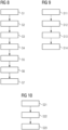
- Fig. 8 shows a block diagram of a method for connecting two blade portions 12, 13.
- a step S1 the blade portion 12 and the blade portion 13 are provided.
- the blade portions may be provided by means of casting.
- a step S2 a plurality of markers 20 are provided on the blade portion 12 and a plurality of markers 22 are provided on the blade portion 13.
- initial positions e.g. when the blade portions lie in the molds 14, 15, see Fig. 3
- the markers 20, 22 are provided at predetermined positions at the blade portions 12, 13.
- step S4 target positions of the markers 20, 22 are determined. This can be executed by means of calculating the target positions for a connected blade 5, wherein the initial positions obtained in step S3 may be used as input values.
- step S5 detecting means 49 are provided for detecting actual positions of the markers 20, 22.
- a step S6 the blade portions 12, 13 are aligned to each other and the actual positions of the markers 20, 22 are compared with the target positions until an acceptable deviation is obtained.
- a step S7 the blade portions 12, 13 are connected together. In particular, the actual positions of the markers 20, 21 are detected by the detecting means 49 during step S7.
- Fig. 9 shows a block diagram of a method for producing a wind turbine.
- the blade 5 which is ready to mount is provided, wherein the blade 5 is provided by the method for connecting two wind turbine blade portions 12, 13 (see Fig. 8 ).
- the tower 4 is provided and sited.
- a nacelle 3 and a hub 6 are connected to the tower 4.
- a blade 5 is connected to the hub 6 of the wind turbine 1.
- Fig. 10 shows a block diagram of a method for connecting two molded portions 12, 13.
- a portion 12 is molded by means of a mold 14 and a portion 13 is molded by means of a mold 15.
- markers 20 are provided (e.g. set) on the portion 12 when the portion 12 is (e.g. lies) in the mold 14 and markers 22 are provided (e.g. set) on the portion 13 when the portion 13 is (e.g. lies) in the mold 15.
- portions 12, 13 are connected together by means of the markers 20, 22 to form a component, in particular a blade 5. Therefore, a shape accuracy of two connected portions can be improved.
Landscapes
- Engineering & Computer Science (AREA)
- Mechanical Engineering (AREA)
- Life Sciences & Earth Sciences (AREA)
- Sustainable Development (AREA)
- Sustainable Energy (AREA)
- Chemical & Material Sciences (AREA)
- Combustion & Propulsion (AREA)
- General Engineering & Computer Science (AREA)
- Power Engineering (AREA)
- Physics & Mathematics (AREA)
- Fluid Mechanics (AREA)
- Wind Motors (AREA)
Claims (13)
- Verfahren zum Verbinden zweier Windturbinenschaufelteile (12, 13), wobei das Verfahren die folgenden Schritte umfasst:a) Bereitstellen (S1) eines ersten Windturbinenschaufelteils (12) und eines zweiten Windturbinenschaufelteils (13),b) Bereitstellen (S2) einer Vielzahl von ersten Markierungen (20) auf dem ersten Schaufelteil (12) und Bereitstellen einer Vielzahl von zweiten Markierungen (22) auf dem zweiten Schaufelteil (13),c) Bestimmen (S4) der Soll-Positionen der ersten Markierungen (20) und der zweiten Markierungen (22),d) Ausrichten (S6) der Windturbinenschaufelteile (12, 13) zueinander und Vergleichen der Ist-Positionen der ersten Markierungen (20) und der zweiten Markierungen (21) mit den Soll-Positionen, wobei Schritt d) mittels digitaler Bildkorrelation ausgeführt wird, unde) Verbinden (S7) der Windturbinenschaufelteile (12, 13) miteinander.
- Verfahren nach Anspruch 1,
wobei in Schritt a) das erste Windturbinenschaufelteil (12) mittels einer ersten Form (14) und das zweite Windturbinenschaufelteil (13) mittels einer zweiten Form (15) geformt wird. - Verfahren nach Anspruch 2,
wobei Schritt b) ausgeführt wird, wenn sich das erste Windturbinenschaufelteil (12) in der ersten Form (14) und/oder das zweite Windturbinenschaufelteil (13) in der zweiten Form (15) befindet. - Verfahren nach einem der Ansprüche 1 - 3,
wobei die Anfangspositionen der ersten und der zweiten Markierung (20, 22) während oder unmittelbar nach Schritt b) bestimmt werden. - Verfahren nach Anspruch 4,
wobei die Soll-Positionen der ersten Markierungen (20) und/oder der zweiten Markierungen (22) anhand der Anfangspositionen der ersten Markierungen (20) und/oder der zweiten Markierungen (22) bestimmt werden. - Verfahren nach Anspruch 5,
wobei die Soll-Positionen der ersten Markierungen (20) und der zweiten Markierungen (22) durch Einstellen einer Beziehung zwischen der Anfangsposition der ersten Markierungen (20) relativ zu den Anfangspositionen der zweiten Markierungen (22) bestimmt werden. - Verfahren nach einem der Ansprüche 1 - 6,
wobei die Ist-Positionen der ersten und/oder der zweiten Markierungen (20, 22) während des Schritts d) mithilfe von Erfassungsmitteln (49) erfasst werden. - Verfahren nach einem der Ansprüche 1 - 7,
wobei Schritt d) mittels einer Tragevorrichtung (25) ausgeführt wird, die dazu ausgelegt ist, das erste Windturbinenschaufelteil (12) in mindestens 3, 4, 5 oder 6 Freiheitsgraden relativ zu dem zweiten Windturbinenschaufelteil (13) zu bewegen. - Verfahren nach Anspruch 8,
wobei die Tragevorrichtung (25) dazu ausgelegt ist, das zweite Windturbinenschaufelteil (13) in mindestens 3, 4, 5 oder 6 Freiheitsgraden relativ zu dem ersten Windturbinenschaufelteil (12) zu bewegen. - Verfahren nach einem der Ansprüche 1 - 9,
wobei in Schritt d) und/oder e) die Vorderkanten (10) des ersten und des zweiten Windturbinenschaufelteils (12, 13) nach unten oder nach oben weisen. - Verfahren nach einem der Ansprüche 1 - 10,
wobei die ersten und die zweite Markierungen (20, 22) digital erzeugte Punkte sind und/oder konkret auf dem jeweiligen Windturbinenschaufelteil (12, 13) erzeugt werden. - Verfahren nach einem der Ansprüche 1 - 11,
wobei das erste Windturbinenschaufelteil (12) und das zweite Windturbinenschaufelteil (13) Längssegmente einer Windturbinenschaufel (5) sind. - Verfahren zur Herstellung einer Windturbine (1), wobei das Verfahren die folgenden Schritte umfasst:a2) Verbinden (S11) zweier Windturbinenschaufelteile (12, 13) gemäß dem Verfahren nach einem der Ansprüche 1 - 12, sodass eine Windturbinenschaufel (5) bereitgestellt wird, undb2) Verbinden (S14) der Windturbinenschaufel (5) mit einer Nabe (6) der Windturbine (1).
Priority Applications (6)
| Application Number | Priority Date | Filing Date | Title |
|---|---|---|---|
| EP19185181.5A EP3763938B1 (de) | 2019-07-09 | 2019-07-09 | Verfahren zur verbindung von zwei windturbinenschaufelteilen, verfahren zur herstellung einer windturbine und verfahren zum verbinden von zwei formteilen |
| PL19185181.5T PL3763938T3 (pl) | 2019-07-09 | 2019-07-09 | Sposób łączenia dwóch części łopatki turbiny wiatrowej, sposób produkcji turbiny wiatrowej oraz sposób łączenia dwóch części formowanych |
| DK19185181.5T DK3763938T3 (da) | 2019-07-09 | 2019-07-09 | Fremgangsmåde til sammensætning af to vindmøllerotorbladsdele, fremgangsmåde til fremstilling af en vindmølle og fremgangsmåde til sammensætning af to formdele |
| US16/916,479 US12297801B2 (en) | 2019-07-09 | 2020-06-30 | Method for connecting two wind turbine blade portions, method for producing a wind turbine, and method for connecting two molded portions |
| TW109122738A TWI758769B (zh) | 2019-07-09 | 2020-07-06 | 用於連接兩個風力渦輪機葉片部分的方法、用於製造風力渦輪機的方法以及用於連接兩個模製部分的方法 |
| CN202010656806.1A CN112211777B (zh) | 2019-07-09 | 2020-07-09 | 用于连接两个风力涡轮机叶片部分、制造风力涡轮机以及连接两个模制部分的方法 |
Applications Claiming Priority (1)
| Application Number | Priority Date | Filing Date | Title |
|---|---|---|---|
| EP19185181.5A EP3763938B1 (de) | 2019-07-09 | 2019-07-09 | Verfahren zur verbindung von zwei windturbinenschaufelteilen, verfahren zur herstellung einer windturbine und verfahren zum verbinden von zwei formteilen |
Publications (2)
| Publication Number | Publication Date |
|---|---|
| EP3763938A1 EP3763938A1 (de) | 2021-01-13 |
| EP3763938B1 true EP3763938B1 (de) | 2024-09-11 |
Family
ID=67220715
Family Applications (1)
| Application Number | Title | Priority Date | Filing Date |
|---|---|---|---|
| EP19185181.5A Active EP3763938B1 (de) | 2019-07-09 | 2019-07-09 | Verfahren zur verbindung von zwei windturbinenschaufelteilen, verfahren zur herstellung einer windturbine und verfahren zum verbinden von zwei formteilen |
Country Status (6)
| Country | Link |
|---|---|
| US (1) | US12297801B2 (de) |
| EP (1) | EP3763938B1 (de) |
| CN (1) | CN112211777B (de) |
| DK (1) | DK3763938T3 (de) |
| PL (1) | PL3763938T3 (de) |
| TW (1) | TWI758769B (de) |
Families Citing this family (4)
| Publication number | Priority date | Publication date | Assignee | Title |
|---|---|---|---|---|
| EP3808543A1 (de) * | 2019-10-18 | 2021-04-21 | Siemens Gamesa Renewable Energy A/S | Verfahren und system zur montage von schaufelteilen einer windturbinenschaufel |
| EP4066987A1 (de) * | 2021-04-01 | 2022-10-05 | Siemens Gamesa Renewable Energy A/S | Verfahren zur herstellung einer windturbinenschaufel |
| CN117072372B (zh) * | 2023-08-30 | 2025-12-19 | 中电投张北风力发电有限公司 | 风电叶片涡流发生器安装辅助工装及其使用方法 |
| EP4563813A1 (de) * | 2023-11-30 | 2025-06-04 | LM Wind Power A/S | Schaufelhandhabungsanordnung zum bewegen einer windturbinenschaufel zwischen verschiedenen orten |
Citations (1)
| Publication number | Priority date | Publication date | Assignee | Title |
|---|---|---|---|---|
| KR20140001636A (ko) * | 2012-06-28 | 2014-01-07 | 삼성중공업 주식회사 | 풍력발전기용 블레이드 설치장치 및 이를 이용한 풍력발전기용 블레이드 설치방법 |
Family Cites Families (15)
| Publication number | Priority date | Publication date | Assignee | Title |
|---|---|---|---|---|
| US8240962B2 (en) * | 2007-12-28 | 2012-08-14 | General Electric Company | Integrated shipping fixture and assembly method for jointed wind turbine blades |
| WO2010135737A1 (en) | 2009-05-22 | 2010-11-25 | Modular Wind Energy, Inc. | Systems and methods for transporting and assembling segmented wind turbine blades |
| EP2305998B1 (de) * | 2009-09-29 | 2016-06-15 | Vestas Wind Systems A/S | Form zur Herstellung von Windturbinenschaufeln |
| RU94936U1 (ru) * | 2010-02-04 | 2010-06-10 | Открытое Акционерное Общество "Российские Железные Дороги" | Система контроля деформации рельсовых плетей бесстыкового железнодорожного пути |
| DE102010002230B4 (de) * | 2010-02-23 | 2014-11-27 | Senvion Se | Verfahren und Vorrichtung zum Anbringen einer Referenzmarkierung an einem Rotorblatt für eine Windenergieanlage |
| DK2481559T3 (da) * | 2011-02-01 | 2019-07-29 | Siemens Gamesa Renewable Energy As | Forberedelse af en vindmøllevinge til korrekt positionering i et efterfølgende samlingstrin |
| CN102629700A (zh) | 2012-04-28 | 2012-08-08 | 无锡合志科技有限公司 | 一种使用锂电池材料的通用电池结构 |
| KR101707278B1 (ko) | 2013-02-25 | 2017-02-15 | 가부시키가이샤 스크린 홀딩스 | 패턴 형성 장치 및 패턴 형성 방법 및 얼라이먼트 장치 및 얼라이먼트 방법 |
| EP2969915B1 (de) * | 2013-03-14 | 2018-09-12 | Stratec Consumables GmbH | Mikrofluidische vorrichtung |
| JP6234074B2 (ja) * | 2013-06-07 | 2017-11-22 | オリンパス株式会社 | 半導体装置、固体撮像装置、および撮像装置 |
| BR112016024391B1 (pt) * | 2014-04-24 | 2021-07-06 | Lm Wp Patent Holding A/S | sistema e método para fabricação de pá de turbina eólica |
| US10668673B2 (en) * | 2015-05-18 | 2020-06-02 | Flightware, Inc. | Systems and methods for automated composite layup quality assurance |
| CN110177933B (zh) * | 2016-11-21 | 2021-11-12 | Lm风力发电国际技术有限公司 | 用于建立分段的或模块化的风力涡轮机叶片的方法和系统、以及用于联结风力涡轮机叶片的段的移动工厂 |
| DE102016123188A1 (de) * | 2016-12-01 | 2018-06-07 | Dr. Ing. H.C. F. Porsche Aktiengesellschaft | Justierbarer Laderoboter |
| WO2018215457A1 (en) * | 2017-05-22 | 2018-11-29 | Lm Wind Power International Technology Ii Aps | Wind turbine blade and method of assembly of blade elements to form a wind turbine blade |
-
2019
- 2019-07-09 EP EP19185181.5A patent/EP3763938B1/de active Active
- 2019-07-09 DK DK19185181.5T patent/DK3763938T3/da active
- 2019-07-09 PL PL19185181.5T patent/PL3763938T3/pl unknown
-
2020
- 2020-06-30 US US16/916,479 patent/US12297801B2/en active Active
- 2020-07-06 TW TW109122738A patent/TWI758769B/zh active
- 2020-07-09 CN CN202010656806.1A patent/CN112211777B/zh active Active
Patent Citations (1)
| Publication number | Priority date | Publication date | Assignee | Title |
|---|---|---|---|---|
| KR20140001636A (ko) * | 2012-06-28 | 2014-01-07 | 삼성중공업 주식회사 | 풍력발전기용 블레이드 설치장치 및 이를 이용한 풍력발전기용 블레이드 설치방법 |
Also Published As
| Publication number | Publication date |
|---|---|
| DK3763938T3 (da) | 2024-11-04 |
| EP3763938A1 (de) | 2021-01-13 |
| TWI758769B (zh) | 2022-03-21 |
| CN112211777B (zh) | 2025-09-16 |
| US20210010460A1 (en) | 2021-01-14 |
| PL3763938T3 (pl) | 2024-12-09 |
| US12297801B2 (en) | 2025-05-13 |
| CN112211777A (zh) | 2021-01-12 |
| TW202113226A (zh) | 2021-04-01 |
Similar Documents
| Publication | Publication Date | Title |
|---|---|---|
| US12297801B2 (en) | Method for connecting two wind turbine blade portions, method for producing a wind turbine, and method for connecting two molded portions | |
| CN101868620B (zh) | 用于测量风能设备的中空部件从基准位置偏移的方法和系统 | |
| EP2935875B1 (de) | Scherungsnetzausrichtungsverfahren für eine turbinenschaufel | |
| CN104245266B (zh) | 供风轮机叶片的模具壳体用的模具壳体段、模具壳体以及使用该模具壳体段的方法 | |
| US11794379B2 (en) | Turning system for wind turbine blade parts | |
| JP2017115787A (ja) | 風力発電設備のメンテナンス方法および無人飛行機 | |
| EP3468759B1 (de) | Schaufelform zur herstellung eines schaufelhüllenteils einer windturbinenschaufel und zugehöriges verfahren | |
| US10328640B2 (en) | Wind turbine blade manufacturing system and method | |
| US20200332762A1 (en) | A wind turbine blade comprising a root end structure with a pultruded element having a transition portion | |
| EP1508691A1 (de) | Windkraftanlage mit waagerechter Welle und Verfahren zur Messung des Aufwärtsströmungswinkels | |
| WO2017110743A1 (ja) | 大型構造物のメンテナンス方法および風力発電設備のメンテナンス方法ならびに無人飛行機 | |
| CN119895144A (zh) | 用于调准风力设施的转子叶片的叶片负荷测量系统的计算机实现的方法和设备、具有带有应变传感器的至少一个转子叶片的风力设施和计算机可读的存储介质 | |
| US7966865B2 (en) | Method for balancing radical projections detached from a rotating assembly | |
| CN112955310A (zh) | 检测系统、方法及其检测装置 | |
| US20210016533A1 (en) | Moulding station for shear web production and a manufacturing method thereof | |
| CN117433695B (zh) | 一种风力发电机叶片载荷的标定方法 | |
| EP4563813A1 (de) | Schaufelhandhabungsanordnung zum bewegen einer windturbinenschaufel zwischen verschiedenen orten | |
| EP4491383A1 (de) | Positionierung von holmkappen in klingenformen | |
| TWI818472B (zh) | 用於製造風力渦輪機葉片的方法 | |
| EP4186683B1 (de) | System und verfahren zum zusammenbau der schale einer windturbinenschaufel | |
| EP4582236A1 (de) | Verfahren zum positionieren eines vorformteils zur herstellung eines windturbinen- oder vorformelements | |
| CN121241200A (zh) | 一种用于将风力涡轮机转子叶片安装到毂的方法 | |
| US20230025179A1 (en) | Method for manufacturing a wind turbine blade and an apparatus for manufacturing a wind turbine blade | |
| DK202170372A1 (en) | System and method for performing nondestructive scans of a wind turbine blade |
Legal Events
| Date | Code | Title | Description |
|---|---|---|---|
| PUAI | Public reference made under article 153(3) epc to a published international application that has entered the european phase |
Free format text: ORIGINAL CODE: 0009012 |
|
| STAA | Information on the status of an ep patent application or granted ep patent |
Free format text: STATUS: THE APPLICATION HAS BEEN PUBLISHED |
|
| AK | Designated contracting states |
Kind code of ref document: A1 Designated state(s): AL AT BE BG CH CY CZ DE DK EE ES FI FR GB GR HR HU IE IS IT LI LT LU LV MC MK MT NL NO PL PT RO RS SE SI SK SM TR |
|
| STAA | Information on the status of an ep patent application or granted ep patent |
Free format text: STATUS: REQUEST FOR EXAMINATION WAS MADE |
|
| 17P | Request for examination filed |
Effective date: 20210713 |
|
| RBV | Designated contracting states (corrected) |
Designated state(s): AL AT BE BG CH CY CZ DE DK EE ES FI FR GB GR HR HU IE IS IT LI LT LU LV MC MK MT NL NO PL PT RO RS SE SI SK SM TR |
|
| STAA | Information on the status of an ep patent application or granted ep patent |
Free format text: STATUS: EXAMINATION IS IN PROGRESS |
|
| 17Q | First examination report despatched |
Effective date: 20220921 |
|
| GRAP | Despatch of communication of intention to grant a patent |
Free format text: ORIGINAL CODE: EPIDOSNIGR1 |
|
| STAA | Information on the status of an ep patent application or granted ep patent |
Free format text: STATUS: GRANT OF PATENT IS INTENDED |
|
| RIC1 | Information provided on ipc code assigned before grant |
Ipc: B29L 31/08 20060101ALI20240313BHEP Ipc: B29C 65/00 20060101ALI20240313BHEP Ipc: B29C 65/78 20060101ALI20240313BHEP Ipc: F03D 1/06 20060101AFI20240313BHEP |
|
| INTG | Intention to grant announced |
Effective date: 20240328 |
|
| RIN1 | Information on inventor provided before grant (corrected) |
Inventor name: NIELSEN, MOGENS Inventor name: HENRICHSEN, SOEREN RANDRUP DAUGAARD |
|
| GRAS | Grant fee paid |
Free format text: ORIGINAL CODE: EPIDOSNIGR3 |
|
| GRAA | (expected) grant |
Free format text: ORIGINAL CODE: 0009210 |
|
| STAA | Information on the status of an ep patent application or granted ep patent |
Free format text: STATUS: THE PATENT HAS BEEN GRANTED |
|
| AK | Designated contracting states |
Kind code of ref document: B1 Designated state(s): AL AT BE BG CH CY CZ DE DK EE ES FI FR GB GR HR HU IE IS IT LI LT LU LV MC MK MT NL NO PL PT RO RS SE SI SK SM TR |
|
| REG | Reference to a national code |
Ref country code: GB Ref legal event code: FG4D |
|
| REG | Reference to a national code |
Ref country code: CH Ref legal event code: EP |
|
| REG | Reference to a national code |
Ref country code: DE Ref legal event code: R096 Ref document number: 602019058603 Country of ref document: DE |
|
| REG | Reference to a national code |
Ref country code: IE Ref legal event code: FG4D |
|
| REG | Reference to a national code |
Ref country code: DK Ref legal event code: T3 Effective date: 20241029 |
|
| REG | Reference to a national code |
Ref country code: NL Ref legal event code: FP |
|
| REG | Reference to a national code |
Ref country code: LT Ref legal event code: MG9D |
|
| PG25 | Lapsed in a contracting state [announced via postgrant information from national office to epo] |
Ref country code: NO Free format text: LAPSE BECAUSE OF FAILURE TO SUBMIT A TRANSLATION OF THE DESCRIPTION OR TO PAY THE FEE WITHIN THE PRESCRIBED TIME-LIMIT Effective date: 20241211 |
|
| PG25 | Lapsed in a contracting state [announced via postgrant information from national office to epo] |
Ref country code: GR Free format text: LAPSE BECAUSE OF FAILURE TO SUBMIT A TRANSLATION OF THE DESCRIPTION OR TO PAY THE FEE WITHIN THE PRESCRIBED TIME-LIMIT Effective date: 20241212 Ref country code: FI Free format text: LAPSE BECAUSE OF FAILURE TO SUBMIT A TRANSLATION OF THE DESCRIPTION OR TO PAY THE FEE WITHIN THE PRESCRIBED TIME-LIMIT Effective date: 20240911 |
|
| PG25 | Lapsed in a contracting state [announced via postgrant information from national office to epo] |
Ref country code: BG Free format text: LAPSE BECAUSE OF FAILURE TO SUBMIT A TRANSLATION OF THE DESCRIPTION OR TO PAY THE FEE WITHIN THE PRESCRIBED TIME-LIMIT Effective date: 20240911 |
|
| PG25 | Lapsed in a contracting state [announced via postgrant information from national office to epo] |
Ref country code: LV Free format text: LAPSE BECAUSE OF FAILURE TO SUBMIT A TRANSLATION OF THE DESCRIPTION OR TO PAY THE FEE WITHIN THE PRESCRIBED TIME-LIMIT Effective date: 20240911 |
|
| PG25 | Lapsed in a contracting state [announced via postgrant information from national office to epo] |
Ref country code: HR Free format text: LAPSE BECAUSE OF FAILURE TO SUBMIT A TRANSLATION OF THE DESCRIPTION OR TO PAY THE FEE WITHIN THE PRESCRIBED TIME-LIMIT Effective date: 20240911 |
|
| PG25 | Lapsed in a contracting state [announced via postgrant information from national office to epo] |
Ref country code: RS Free format text: LAPSE BECAUSE OF FAILURE TO SUBMIT A TRANSLATION OF THE DESCRIPTION OR TO PAY THE FEE WITHIN THE PRESCRIBED TIME-LIMIT Effective date: 20241211 Ref country code: ES Free format text: LAPSE BECAUSE OF FAILURE TO SUBMIT A TRANSLATION OF THE DESCRIPTION OR TO PAY THE FEE WITHIN THE PRESCRIBED TIME-LIMIT Effective date: 20240911 |
|
| PG25 | Lapsed in a contracting state [announced via postgrant information from national office to epo] |
Ref country code: RS Free format text: LAPSE BECAUSE OF FAILURE TO SUBMIT A TRANSLATION OF THE DESCRIPTION OR TO PAY THE FEE WITHIN THE PRESCRIBED TIME-LIMIT Effective date: 20241211 Ref country code: NO Free format text: LAPSE BECAUSE OF FAILURE TO SUBMIT A TRANSLATION OF THE DESCRIPTION OR TO PAY THE FEE WITHIN THE PRESCRIBED TIME-LIMIT Effective date: 20241211 Ref country code: LV Free format text: LAPSE BECAUSE OF FAILURE TO SUBMIT A TRANSLATION OF THE DESCRIPTION OR TO PAY THE FEE WITHIN THE PRESCRIBED TIME-LIMIT Effective date: 20240911 Ref country code: HR Free format text: LAPSE BECAUSE OF FAILURE TO SUBMIT A TRANSLATION OF THE DESCRIPTION OR TO PAY THE FEE WITHIN THE PRESCRIBED TIME-LIMIT Effective date: 20240911 Ref country code: GR Free format text: LAPSE BECAUSE OF FAILURE TO SUBMIT A TRANSLATION OF THE DESCRIPTION OR TO PAY THE FEE WITHIN THE PRESCRIBED TIME-LIMIT Effective date: 20241212 Ref country code: FI Free format text: LAPSE BECAUSE OF FAILURE TO SUBMIT A TRANSLATION OF THE DESCRIPTION OR TO PAY THE FEE WITHIN THE PRESCRIBED TIME-LIMIT Effective date: 20240911 Ref country code: ES Free format text: LAPSE BECAUSE OF FAILURE TO SUBMIT A TRANSLATION OF THE DESCRIPTION OR TO PAY THE FEE WITHIN THE PRESCRIBED TIME-LIMIT Effective date: 20240911 Ref country code: BG Free format text: LAPSE BECAUSE OF FAILURE TO SUBMIT A TRANSLATION OF THE DESCRIPTION OR TO PAY THE FEE WITHIN THE PRESCRIBED TIME-LIMIT Effective date: 20240911 |
|
| REG | Reference to a national code |
Ref country code: AT Ref legal event code: MK05 Ref document number: 1722882 Country of ref document: AT Kind code of ref document: T Effective date: 20240911 |
|
| PG25 | Lapsed in a contracting state [announced via postgrant information from national office to epo] |
Ref country code: IS Free format text: LAPSE BECAUSE OF FAILURE TO SUBMIT A TRANSLATION OF THE DESCRIPTION OR TO PAY THE FEE WITHIN THE PRESCRIBED TIME-LIMIT Effective date: 20250111 Ref country code: PT Free format text: LAPSE BECAUSE OF FAILURE TO SUBMIT A TRANSLATION OF THE DESCRIPTION OR TO PAY THE FEE WITHIN THE PRESCRIBED TIME-LIMIT Effective date: 20250113 |
|
| PG25 | Lapsed in a contracting state [announced via postgrant information from national office to epo] |
Ref country code: RO Free format text: LAPSE BECAUSE OF FAILURE TO SUBMIT A TRANSLATION OF THE DESCRIPTION OR TO PAY THE FEE WITHIN THE PRESCRIBED TIME-LIMIT Effective date: 20240911 Ref country code: SM Free format text: LAPSE BECAUSE OF FAILURE TO SUBMIT A TRANSLATION OF THE DESCRIPTION OR TO PAY THE FEE WITHIN THE PRESCRIBED TIME-LIMIT Effective date: 20240911 |
|
| PG25 | Lapsed in a contracting state [announced via postgrant information from national office to epo] |
Ref country code: EE Free format text: LAPSE BECAUSE OF FAILURE TO SUBMIT A TRANSLATION OF THE DESCRIPTION OR TO PAY THE FEE WITHIN THE PRESCRIBED TIME-LIMIT Effective date: 20240911 Ref country code: AT Free format text: LAPSE BECAUSE OF FAILURE TO SUBMIT A TRANSLATION OF THE DESCRIPTION OR TO PAY THE FEE WITHIN THE PRESCRIBED TIME-LIMIT Effective date: 20240911 |
|
| PG25 | Lapsed in a contracting state [announced via postgrant information from national office to epo] |
Ref country code: CZ Free format text: LAPSE BECAUSE OF FAILURE TO SUBMIT A TRANSLATION OF THE DESCRIPTION OR TO PAY THE FEE WITHIN THE PRESCRIBED TIME-LIMIT Effective date: 20240911 |
|
| PG25 | Lapsed in a contracting state [announced via postgrant information from national office to epo] |
Ref country code: IT Free format text: LAPSE BECAUSE OF FAILURE TO SUBMIT A TRANSLATION OF THE DESCRIPTION OR TO PAY THE FEE WITHIN THE PRESCRIBED TIME-LIMIT Effective date: 20240911 Ref country code: SK Free format text: LAPSE BECAUSE OF FAILURE TO SUBMIT A TRANSLATION OF THE DESCRIPTION OR TO PAY THE FEE WITHIN THE PRESCRIBED TIME-LIMIT Effective date: 20240911 |
|
| REG | Reference to a national code |
Ref country code: DE Ref legal event code: R097 Ref document number: 602019058603 Country of ref document: DE |
|
| PLBE | No opposition filed within time limit |
Free format text: ORIGINAL CODE: 0009261 |
|
| STAA | Information on the status of an ep patent application or granted ep patent |
Free format text: STATUS: NO OPPOSITION FILED WITHIN TIME LIMIT |
|
| PGFP | Annual fee paid to national office [announced via postgrant information from national office to epo] |
Ref country code: NL Payment date: 20250724 Year of fee payment: 7 |
|
| 26N | No opposition filed |
Effective date: 20250612 |
|
| PG25 | Lapsed in a contracting state [announced via postgrant information from national office to epo] |
Ref country code: SE Free format text: LAPSE BECAUSE OF FAILURE TO SUBMIT A TRANSLATION OF THE DESCRIPTION OR TO PAY THE FEE WITHIN THE PRESCRIBED TIME-LIMIT Effective date: 20240911 |
|
| PGFP | Annual fee paid to national office [announced via postgrant information from national office to epo] |
Ref country code: DE Payment date: 20250728 Year of fee payment: 7 Ref country code: DK Payment date: 20250725 Year of fee payment: 7 |
|
| PGFP | Annual fee paid to national office [announced via postgrant information from national office to epo] |
Ref country code: GB Payment date: 20250722 Year of fee payment: 7 |
|
| PGFP | Annual fee paid to national office [announced via postgrant information from national office to epo] |
Ref country code: FR Payment date: 20250725 Year of fee payment: 7 |
|
| PGFP | Annual fee paid to national office [announced via postgrant information from national office to epo] |
Ref country code: PL Payment date: 20250616 Year of fee payment: 7 |
|
| REG | Reference to a national code |
Ref country code: CH Ref legal event code: H13 Free format text: ST27 STATUS EVENT CODE: U-0-0-H10-H13 (AS PROVIDED BY THE NATIONAL OFFICE) Effective date: 20260224 |
|
| PG25 | Lapsed in a contracting state [announced via postgrant information from national office to epo] |
Ref country code: LU Free format text: LAPSE BECAUSE OF NON-PAYMENT OF DUE FEES Effective date: 20250709 |
|
| REG | Reference to a national code |
Ref country code: BE Ref legal event code: MM Effective date: 20250731 |
|
| PG25 | Lapsed in a contracting state [announced via postgrant information from national office to epo] |
Ref country code: BE Free format text: LAPSE BECAUSE OF NON-PAYMENT OF DUE FEES Effective date: 20250731 |