EP3763939B1 - Système et procédé permettant de déterminer le désalignement de lacet d'une éolienne terrestre à axe horizontal - Google Patents
Système et procédé permettant de déterminer le désalignement de lacet d'une éolienne terrestre à axe horizontal Download PDFInfo
- Publication number
- EP3763939B1 EP3763939B1 EP20465522.9A EP20465522A EP3763939B1 EP 3763939 B1 EP3763939 B1 EP 3763939B1 EP 20465522 A EP20465522 A EP 20465522A EP 3763939 B1 EP3763939 B1 EP 3763939B1
- Authority
- EP
- European Patent Office
- Prior art keywords
- computing unit
- nacelle
- angle
- wind
- turbine
- Prior art date
- Legal status (The legal status is an assumption and is not a legal conclusion. Google has not performed a legal analysis and makes no representation as to the accuracy of the status listed.)
- Active
Links
Images

Classifications
-
- F—MECHANICAL ENGINEERING; LIGHTING; HEATING; WEAPONS; BLASTING
- F03—MACHINES OR ENGINES FOR LIQUIDS; WIND, SPRING, OR WEIGHT MOTORS; PRODUCING MECHANICAL POWER OR A REACTIVE PROPULSIVE THRUST, NOT OTHERWISE PROVIDED FOR
- F03D—WIND MOTORS
- F03D7/00—Controlling wind motors
- F03D7/02—Controlling wind motors the wind motors having rotation axis substantially parallel to the air flow entering the rotor
- F03D7/0204—Controlling wind motors the wind motors having rotation axis substantially parallel to the air flow entering the rotor for orientation in relation to wind direction
-
- F—MECHANICAL ENGINEERING; LIGHTING; HEATING; WEAPONS; BLASTING
- F03—MACHINES OR ENGINES FOR LIQUIDS; WIND, SPRING, OR WEIGHT MOTORS; PRODUCING MECHANICAL POWER OR A REACTIVE PROPULSIVE THRUST, NOT OTHERWISE PROVIDED FOR
- F03D—WIND MOTORS
- F03D17/00—Monitoring or testing of wind motors, e.g. diagnostics
-
- Y—GENERAL TAGGING OF NEW TECHNOLOGICAL DEVELOPMENTS; GENERAL TAGGING OF CROSS-SECTIONAL TECHNOLOGIES SPANNING OVER SEVERAL SECTIONS OF THE IPC; TECHNICAL SUBJECTS COVERED BY FORMER USPC CROSS-REFERENCE ART COLLECTIONS [XRACs] AND DIGESTS
- Y02—TECHNOLOGIES OR APPLICATIONS FOR MITIGATION OR ADAPTATION AGAINST CLIMATE CHANGE
- Y02E—REDUCTION OF GREENHOUSE GAS [GHG] EMISSIONS, RELATED TO ENERGY GENERATION, TRANSMISSION OR DISTRIBUTION
- Y02E10/00—Energy generation through renewable energy sources
- Y02E10/70—Wind energy
- Y02E10/72—Wind turbines with rotation axis in wind direction
Definitions
- the invention is related to the field of wind turbines.
- the invention is related to a system and method for determining the wind yaw misalignment of a horizontal axis on-shore wind turbine, to a computer program and to a computing unit for carrying the method.
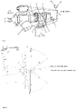
- the main components of an on-shore wind turbine are as follows, with reference to Fig.1 .
- the on-shore wind turbines are of two types: horizontal axis wind turbines, when the two shafts, namely the low- and high-speed shaft are parallel to the ground and vertical axis wind turbines, when the two shafts are perpendicular to the ground.
- turbine or “wind turbine”, used alternatively, shall refer to the horizontal axis on-shore wind turbines.
- in front of the turbine relates to the position in front of the rotor blades that is the direction from where the wind blows, said wind being called “inflow wind” whereas the term “behind the turbine” refers to the position opposite to the rotor blades that is the direction from where the wind blows away from the turbine.
- the wind turbines use the so-called “yaw mechanism” alternatively called “yawing” or “yaw alignment”, all terms designating a process by which an actuator is used to turn the nacelle of the wind turbine with the rotor to the wind.
- the expression “re-align the wind turbine with the wind” is used in this invention to define the situation when the nacelle is aligned such that it is parallel with the wind.
- the yaw mechanism is operated by an actuator, said actuator being operated in turn either by the turbine computing unit or by the anemometer.
- misalignment refers to the relative change of the direction of the nacelle in respect to the direction of the wind. Ideally, when the nacelle is aligned with the wind, the misalignment is of 0°.
- wind direction stands for the horizontal component of the wind essentially at the hub height
- wind speed stands for the horizontal component of the wind essentially at the hub height
- the term "essentially at the hub height” refers to the hub height measured vertically from the ground to the horizontal axis of the rotor hub with a tolerance + of up to 3 meters due to the usual dimensions of the rotor hub and due to usual location of the ensemble anemometer and wind vane opposite the rotor hub in respect to the rotor shaft and above said rotor shaft.
- the wind yaw misalignment is determined by the ensemble anemometer and wind vane.
- Modern anemometers carry out an average of the misalignment for a pre-determined yaw interval of time and, if said average is above a pre-determined misalignment threshold, send instructions either to the turbine computing unit or directly to the actuator, in order to re-align the wind turbine with the wind.
- the main errors using lidar for the determination of the misalignment of the wind turbine as observed by the inventors refer to the GPS orientation of the internal compass of the lidar and to the fact that in some locations the GPS signal was systematically weak.
- the problem solved by the invention is to improve the accuracy of the determination of the wind yaw misalignment of a horizontal axis on-shore wind turbine.
- a system for determining the wind yaw misalignment of a horizontal axis on-shore wind turbine T comprising the wind turbine T, said wind turbine T comprising a plurality of rotor blades 1, a rotor hub 2 situated at a hub height HH, a rotor shaft 3 having a rotor shaft 3 horizontal axis, a nacelle 4, a tower 5 having a tower base: wherein said wind turbine T further comprises a pair of target points X and Y on the external surface of the nacelle 4 on its side facing the ground arranged such that their geographical positions are determinable by a topographic station S, and such that the segment XY connecting the target points X and Y corresponds to the longitudinal axis of said side of the nacelle 4 facing the ground, target point X being placed at the extremity of the nacelle 4 opposed to the plurality of rotor blades 1 and target point Y being placed in the immediate vicinity of the tower 5;
- a method for determining the wind yaw misalignment of the horizontal axis on-shore wind turbine T using the system according to the invention comprising the following steps to be carried out during the duration ⁇ t: S1 Determining for a n number of times, by the lidar measuring and computing unit LMCU of the ground-based lidar L, of the angle ⁇ of the wind direction in respect to the Geographical North at essentially the hub height HH,
- a computer program comprising instructions which, when the program is executed by the external computing unit EC of the system causes the computer to carry out the steps of the method from step 2 until step 7 inclusive.
- the external computing unit EC of the system having stored thereon the computer program of the third aspect of the invention.
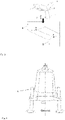
- the system according to the invention comprises the following components, with reference to Fig.2 : a horizontal axis wind turbine T, a ground-based lidar L, a topographic station S, an external computing unit EC, and a communication network N.
- the ground-based lidar L and topographic station S are referred to collectively as input apparatus.
- the turbine T may be any horizontal axis on-shore wind turbine, provided that it is specially configured for the invention as it will be detailed below.
- the wind turbine T comprises a plurality of rotor blades 1, a rotor hub 2 situated at a hub height HH, a rotor shaft 3, a nacelle 4, a tower 5 having a tower base.
- the terms “value” and “determination” are used interchangeably to define in general the result of the determinations of the input apparatus.
- the terms “measurement” refers to the current understanding of the word whereas the term “determination” refers to some computation based on the measurement.
- the terms “instant value” or “instant determination” refer to a value determined at a specific moment of time.
- the turbine T has special configurations.
- the turbine T has a reference position before the measurements and determinations take place, in which the rotor shaft 3 has a rotor shaft 3 horizontal axis reference position.
- the lidar L and the topographic station S are placed in corresponding reference positions using as reference the rotor shaft 3 horizontal axis reference position.
- the wind turbine T is configured to comprise a pair of target points X and Y on the external surface of the nacelle 4 on its side facing the ground arranged such that their geographical positions are determinable by the topographic station S, and such that the segment XY connecting the target points X and Y corresponds to the longitudinal axis of said side facing the ground of the nacelle 4, target point X being placed at the extremity of the nacelle 4 opposed to the plurality of rotor blades 1 and target point Y being placed in the immediate vicinity of the tower 5.
- immediate vicinity refers to a tolerance + of up to 1 meter from the contact point between the nacelle 4 and the tower 5 due to the usual dimensions of the tower 5.
- the lidar L is configured in the invention for the measurement of the wind speed v at essentially the hub height HH, hereafter referred to for simplicity as the wind speed v , and for determining the direction of the wind in respect to the North.
- Using the lidar L as a component of the system according to the invention has the advantage of accurate measurement of the wind speed v , respectively determination of wind direction and the advantage of easy and rapid installation.
- the ground-based lidar L of the system according to the invention hereafter referred to as the lidar L, is mounted on the ground with its axis oriented vertically as shown in Fig. 4 .
- lidar L on the ground instead of placing in on top of the nacelle 4, as customary in the state of art, has the advantage of limiting the impact of disturbances to the measurements by the lidar L due to the interference with the permanent rotation of the blades 1.
- a lidar reference position B the lidar L is placed on the ground in front of the turbine T reference position on the projection on the ground of the rotor shaft 3 horizontal axis reference position, at a distance d 1 from the projection on the ground C1 of an extreme point C of the rotor hub 2 such making an angle ⁇ i between the projection on the ground of the rotor shaft 3 horizontal axis reference position and the projection on the ground of the rotor shaft 3 horizontal axis corresponding to each of the plurality of positions i, when the nacelle 4 moves depending on the wind direction to a plurality of positions i on each side of the projection on the ground of the rotor shaft 3 horizontal axis reference position.
- Fig. 2 shows only one of the positions i from the plurality.
- the lidar L comprises a lidar measuring and computing unit LMCU that includes a lidar high-precision clock.
- the lidar measuring and computing unit LMCU is configured to determine a wind speed v and an angle ⁇ of the wind direction in respect to the Geographical North at essentially the hub height HH.
- the lidar measuring and computing unit LMCU is configured to send via the telecommunication network N to the external computing unit EC the results of the determinations together with a lidar time stamp corresponding to each determination.
- the application of the lidar time stamp to each determination is according to prior art.
- the interval between two successive determinations is called granularity.
- the granularity of the determinations of the lidar L is between 3s and 15s, inclusively, its value does not limit the scope of the invention as it is given for illustrative purpose only.
- the advantage of placing the lidar L as detailed above is that it ensures optimization of the capacity of the lidar L to determine the angle ⁇ of the wind direction and the wind speed v.
- the topographic station S comprises a topographic station measuring and computing unit SMCU having two configurations.
- the first configuration is to determine at least the geographical position of the pair of target points X and Y.
- Some topographic station measuring and computing units SMCU are able to determine, based on the geographical position of the pair of target points X and Y, an angle ⁇ of the orientation of the nacelle 4 made by the segment XY with the North.
- the second configuration is to send the results of determinations together with a topographic station time stamp corresponding to each determination.
- the topographic station S may be either manual, or automated.
- the topographic station measuring and computing unit SMCU includes a theodolite incorporating an electronic distance measurement device and a topographic station global positioning system for orientation of the topographic station S to the North before its use using the current national reference system. The orientation of the topographic station S to the North is carried out according to prior art.
- the ground topographic station S is placed in either of two topographic station reference positions D' and D" behind the rotor hub 2 and laterally in respect to the projection on the ground of the rotor shaft 3 horizontal axis reference position at a distance d 2 from the base of the tower 5, such that, when the nacelle 4 is movable depending on the wind direction:
- the possible positions D' and D" are situated on two imaginary circle sectors having the radius d 2 the center being the base of the tower 5. When it comes to the measurement of the distance d 2 , a tolerance of up to 2m is accepted.
- the determination of the geographical position of the pair of the target points X and Y of the nacelle 4 is made according to prior art.
- the granularity of the determinations that is the interval between two successive determinations m by the topographic station measuring and computing unit SMCU depends on the type of the topographic station S. According to prior art, if the topographic station S is manual, the granularity of interest for the invention typically ranges between 8-15 minutes, whereas if the topographic station S is automated, the granularity typically ranges between 10 and 20s. The afore-mentioned values of granularity are given for illustrative purposes only, they do not limit the scope of the invention.
- the external computing unit EC is a computing machine such as a computer or a plurality of computers located remotely from one another, communicating within a computer communication system.
- the first configuration of the external computing unit EC is to receive input data via the telecommunication network N:
- the external computing unit EC may unify, if necessary, the units of measurement of the angles from the input data, and may to sort same on a time-stamp basis. For example, the external computing unit EC may use as reference for the sorting of the input data the lidar time stamps, based known level of precision the lidar high-precision clock.
- the unification of units of measurement of the angles may be necessary because the input apparatus may have different ways of expressing the measure of the angles: some of them may measure angles in degrees, other in radians, number of digits may be different, the direction of measuring of the angles may be different, etc.
- Another configuration of the external computing unit EC is to determine an angle ⁇ of the orientation of the nacelle 4 in respect to the Geographical North based the geographical position of the pair of target points X and Y, and to store each determination.
- the angle ⁇ of the orientation of the nacelle 4 is made by the segment XY, whose geographical position is determined by the topographic station measuring and computing unit SMCU and the geographical North. From the way the points X and Y are defined, it stems that the orientation of the segment XY in respect to the North corresponds to the orientation of the nacelle 4 to the North.
- This configuration of the external computing unit EC depends on ability of the topographic station measuring and computing unit SMCU to determine the angle ⁇ , namely:
- Another configuration of the external computing unit EC is to apply a validation condition to the angle ⁇ of the wind direction and to determine an adjusted angle ⁇ adj of the wind direction for each of the validated values of the angle ⁇ using a first compass rose condition, and to store the result of this step.
- Another configuration of the external computing unit EC is to average the adjusted angle ⁇ adj of the wind direction and the wind speed v, to verify if the averaged wind speed v avg is comprised within a predetermined interval of wind speeds v 1 - v 2 for which wind yaw misalignment can be determined, and to store the averaged angle ⁇ avg of the wind direction and the averaged wind speed v avg .
- Another configuration of the external computing unit EC is to determine a wind yaw misalignment ⁇ of the turbine T in respect to the wind direction and to store each determination.
- the last configuration of the external computing unit EC is to determine, at the expiry of a duration ⁇ t, an averaged wind yaw misalignment ⁇ avg of the turbine T in respect to the wind direction corresponding to said duration ⁇ t, to store the averaged misalignment ⁇ avg and to compare said average misalignment ⁇ avg with a pre-determined misalignment threshold.
- the telecommunication network N is configured to ensure communication between the external computing unit EC and the lidar measuring and computing unit LMCU and the topographic station measuring and computing unit SMCU.
- the granularity of determinations of the topographic station measuring and computing unit SMCU is larger than a pre-determined time-interval threshold. This is in particular the case when manual topographic station S is used.
- the pre-determined time-interval threshold depends on the granularity of the determinations of the lidar L.
- the granularity of the determinations of the topographic station measuring and computing unit SMCU should not be larger than 150% of the granularity of the determinations of the lidar L.
- the pre-determined time-interval threshold for the determinations of the angle ⁇ of the orientation of the nacelle 4 is 150% x 10s, that is 15s.
- the system further comprises a third input apparatus, namely a turbine computing unit TCU of the turbine T, said turbine computing unit TCU configured to determine an averaged angle ⁇ avg of position of the nacelle 4 in respect to the Geographical North and configured to send the result of the determinations to the external computing unit EC.
- a third input apparatus namely a turbine computing unit TCU of the turbine T, said turbine computing unit TCU configured to determine an averaged angle ⁇ avg of position of the nacelle 4 in respect to the Geographical North and configured to send the result of the determinations to the external computing unit EC.
- Turbine computing unit TCU exists in the absence of the invention, but it is part of the system only if the above condition regarding the pre-determined time-interval threshold is met.
- the granularity of the determinations of the turbine measuring unit TMU is between 8s and 15s, inclusively, its value does not limit the scope of the invention.
- the turbine measuring unit TMU may be, for example, an ultrasonic anemometer.
- the external computing unit EC has further configurations:
- the telecommunication network N is further configured to ensure communication between the external computing unit EC and the turbine computing unit TCU.
- the distance d 1 depends on two parameters: an angle ⁇ of emission of the laser beam spinning around the vertical axis AB of the lidar L on one hand, and the hub height HH on the other hand.
- the laser beam is emitted through spin mirror(s) permanently spinning around the vertical axis AB of the lidar L, the emission of said laser beam is made at the angle of ⁇ .
- the scanning process determines a cone having an angle of 2 ⁇ and the cone origin in point B where the lidar L is placed in the lidar reference position B.
- d 1 max tg ⁇ ⁇ 2 ⁇ HH
- the value of 2 used in the second equation is a constant depending on the characteristics of the lidar L.
- Both minimum and maximum values of the distance d 1 may be rounded. A tolerance of up to 5% is accepted. In the example above d1 min can be rounded up to 60m, whereas d 1max can be rounded to 115m.
- the maximum distance d 2max depends on the possibility that the topographic station measuring and computing unit SMCU determines the geographical position of the points X and Y. Typically the maximum distance d 2max is around 500m for the minimum configuration required for the topographic station S, however its value is not limiting the invention.
- the advantage of placing the topographic station S as described above is that it ensures optimization of the topographic station measuring and computing unit SMCU to determine at least the geographical position of the pair of target points X and Y.
- Both the lidar L and the topographic station S are maintained in their respective corresponding fixed position during the measurements and determinations.
- the external computing unit EC may be placed anywhere in respect to the turbine T, lidar L and topographic station S as long as it is connected via the telecommunication network N to the lidar L and the topographic station S and, respectively in the preferred embodiment using the turbine computing unit TCU to said turbine computing unit TCU.
- the system according to the invention is configured such that the external computing unit EC be able to determine wind yaw misalignment ⁇ avg of the turbine T in respect to the wind direction based on the determinations received from the ground-based topographic station (S), and ground-based lidar L.
- a method for determining the wind yaw misalignment of the horizontal axis on-shore wind turbine T using the system according to the invention comprises seven steps to be carried out during the duration ⁇ t.
- v 1 and v 2 depend on the characteristics of the turbine T, such as but not limited to the size and weight of the turbine T, the hub height HH, the degree of flexibility of the nacelle 4.
- the method is applied for each turbine T for the duration ⁇ t when both the lidar L and the topographic station S are mounted, each in its corresponding reference position at the beginning of the duration ⁇ t, and when the lidar L and the topographic station S are connected via the telecommunication network N to the external computer EC.
- both the lidar L and the topographic station S remain fixed, whereas the nacelle 4 moves depending on the wind direction to a plurality of positions i on each side of the projection on the ground of the rotor shaft 3 horizontal axis reference position.
- the lidar measuring and computing unit LMCU of the ground-based lidar L determines for a n number of times during the duration ⁇ t the angle ⁇ of the wind direction in respect to the Geographical North at essentially the hub height HH.
- the lidar measuring and computing unit LMCU determines the wind speed v at essentially the hub height HH and sends the results of determinations to the external computing unit EC via the telecommunication network N;
- the topographic station measuring and computing unit SMCU determines for a m number of times during the duration ⁇ t, including at the start of said duration ⁇ t, the at least the geographical position of the pair of target points X and Y, and sends the results of determinations together to the external computing unit EC via the telecommunication network N.
- the number m of determinations of the angle ⁇ of the orientation of the nacelle 4 takes place uniformly spanning across the entire duration ⁇ t.
- step 2 of the method the external computing unit EC receives the input data via the telecommunication network N: the angle ⁇ of the wind direction, and the at least geographical position of the pair of target points X and Y.
- the external computing unit EC unifies, if necessary, the units of measurement of the angles, then stores said input data and sorts same on a time-stamp basis using for example as reference the lidar time stamps.
- step 3 of the method the external computing unit EC determines the angle ⁇ of the orientation of the nacelle 4 in respect to the Geographical North based the geographical position of the pair of target points X and Y, and stores the result of this step.
- the external computing unit EC retrieves in this step same angle ⁇ of the orientation of the nacelle 4 as received from the topographic station measuring and computing unit SMCU;
- the external computing unit EC determines in this step the angle ⁇ of the orientation of the nacelle 4 using the geographical position of the pair of target points X and Y received from the topographic station measuring and computing unit SMCU.
- the determined angle ⁇ of the orientation of the nacelle 4 represents an accurate determination of the real orientation of the nacelle 4 in respect to the North, based on the known precision of determinations by the topographic stations in general.
- step 4 of the method the external computing unit EC applies a validation condition by checking if the angle ⁇ of the wind direction has a value which is comprised within the values of a closed interval defined by the pre-determined maximum value ⁇ max of the angle ⁇ i , on each of the sides of the rotor shaft 3 horizontal axis reference position, selects only the values of the angle ⁇ of the wind direction that satisfy said validation condition, and determines an adjusted angle ⁇ adj of the wind direction for each of the validated values using a first compass rose condition, and stores the result of this step.
- the angle of 40° rather than the angle of 320°, this is why adjustment of the angles ⁇ of the wind direction is necessary.
- the errors of determination of the values of the angle ⁇ of the wind direction as received in S2 may occur because of the change of the relative position of the nacelle 4 in respect to the position of the lidar L over the duration ⁇ t, for example the lidar L may be behind the nacelle 4.
- the determinations of the angle ⁇ of the wind direction by the lidar measuring and computing unit LMCU are influenced by the position of the lidar L in respect to the nacelle 4 during the measurements on which determinations of the angle ⁇ of the wind direction are based.
- the inventors came to the conclusion that minimum measurement and determination errors are obtained if the angle ⁇ i on both sides of the rotor shaft 3 horizontal axis does not exceed the maximum pre-determined value ⁇ max . For limiting measurement and determination errors only those instant values of the angle ⁇ of the wind direction determined while the lidar L is in front of the turbine T are validated.
- ⁇ max 30°
- the relative position of the nacelle 4 during the measurements must not exceed 30° in both sides of the rotor shaft 3 horizontal axis in order to validate the values of the angle ⁇ of the wind direction
- the relative position of the lidar L in respect to the nacelle 4 over the duration ⁇ t can be determined knowing the lidar reference position B and the orientation of the nacelle 4 as determined angle ⁇ .
- the lidar reference position B the lidar L is oriented towards North (0°).
- Different compass rose conditions may be set to accommodate specific conditions related to the characteristics of the turbine T such as but not limited to the size and weight of the turbine T, the hub height HH, the degree of flexibility of the nacelle 4, and of the lidar L.
- the first compass rose condition aims to select only those values having absolute values that is modulus of values between 0° and 180°.
- step 5 of the method the external computing unit EC averages for the averaging duration ⁇ tt, where ⁇ tt ⁇ ⁇ t the adjusted angle ⁇ adj of the wind direction, using the values determined in S4 as well as the wind speed v , resulting the averaged angle ⁇ avg of the wind direction and the averaged wind speed v avg .
- the averaging duration ⁇ tt typically ranges between 2-5 min inclusively.
- the external computing unit EC verifies if the averaged wind speed v avg is comprised within the predetermined interval of wind speeds v 1 - v 2 for which the steps 8 to 12 method are applied. If the averaged wind speed v avg is outside the predetermined interval of wind speeds v 1 - v 2 , steps 6 of the method is not applied as long as the averaged wind speed v avg is outside the predetermined interval of wind speeds v 1 - v 2 . However the first four steps of the method are still carried out until the averaged wind speed v avg is comprised again within the predetermined interval of wind speeds v 1 - v 2 .
- the external computing unit EC stores the result of this step.
- the external computing unit EC stores the result of this step.
- step 7 of the method the external computing unit EC determines at the expiry of the duration ⁇ t, the averaged wind yaw misalignment ⁇ avg of the turbine T in respect to the wind direction corresponding to said duration ⁇ t.
- Said averaged wind yaw misalignment ⁇ avg of the turbine T is calculated as an arithmetic mean of the plurality of wind yaw misalignments ⁇ during the duration ⁇ t.
- the averaged wind yaw misalignment ⁇ avg is stored and compared with the pre-determined misalignment threshold in order to check if re-alignment into the wind of the turbine T must be carried out. Should the averaged wind yaw misalignment ⁇ avg of the turbine T be higher than said pre-determined misalignment threshold an action must be taken to re-align the turbine T into the wind, said action being outside the scope of this invention.
- the averaged wind yaw misalignment ⁇ avg of the turbine T as a result of the method according to the invention has the advantage of representing a more accurate determination of the wind yaw misalignment of the turbine T as compared to prior art, because it is determined as an average of a plurality of values of the wind yaw misalignment ⁇ of the turbine T, and each of the values of the wind yaw misalignment ⁇ being determined based on values of the angle ⁇ of the wind direction that are both adjusted to flatten the peak instant values and averaged.
- granularity of determinations of the topographic station measuring and computing unit SMCU is smaller than or equal to the pre-determined time-interval threshold that depends on the granularity of the determinations of the lidar L, it is accurate to use the plurality of instant values of the angle ⁇ of the orientation of the nacelle 4 for the determination of averaged wind yaw misalignment ⁇ avg of the turbine T, because the constant movement of the nacelle 4 is not expected to change radically in sub-minute intervals of times, thus no significant peaks nor errors are expected.
- an adjusted angle ⁇ adj of the orientation of the nacelle 4 is used in S6 instead of the angle ⁇ of the orientation of the nacelle 4.
- the method includes an additional sub-step in step 1 and an additional sub-step in step 2:
- the turbine computing unit TCU determines the averaged angles ⁇ avg of position of the nacelle 4 in respect to the Geographical North and sends same to the external computing unit EC via the telecommunication network N.
- the external computing unit EC receives from the turbine computing unit TCU of the averaged angle ⁇ avg of position of the nacelle 4 via the telecommunication network N;
- the method includes three new steps between S5 and S6.
- the nacelle correction angle k is the difference between the angle ⁇ of the orientation of the nacelle 4 determined by the topographic station S, and respectively the averaged angle ⁇ avg of position of the nacelle 4 by the turbine computing unit TCU reflecting the difference of accuracy when making determinations by the two input apparatus, the topographic station S and the turbine computing unit TCU.
- determination m i of the angle ⁇ of the orientation of the nacelle 4 takes place at 9.00 and the subsequent determination m i+1 of the angle ⁇ of the orientation of the nacelle 4 takes place at 9.15, in this time interval of 15 minutes, the averaged angle ⁇ avg of position of the nacelle 4 has a plurality of instant values, whereas the angle ⁇ of the orientation of the nacelle 4 has a single value, that is the value determined at 9.00. This is why the nacelle correction angles k are averaged.
- the determination of the averaged correction angle k avg of the nacelle 4 may be carried out in different ways taking into account various factors such as but not limited to:
- the averaged correction angle k avg of the nacelle 4 is calculated as an arithmetic mean of the plurality of nacelle correction angles k from the start of the method and up to and including the instant determination of the nacelle correction angle k.
- step 5.2 the external computing unit EC determines a corrected angle ⁇ k of position of the nacelle 4, said corrected angle ⁇ k representing the result of the correction of the averaged angle ⁇ avg of position of the nacelle 4 with the nacelle averaged correction angle k avg , and stores the result of this step.
- the external computing unit EC applies a validation condition by checking if the corrected angle ⁇ k of position of the nacelle 4 has a value which is comprised within the values of a closed interval defined by the pre-determined maximum value ⁇ max of the angle ⁇ i , on each of the sides of the rotor shaft 3 horizontal axis reference position, in order to select only the values of the corrected angle ⁇ k of position of the nacelle 4 that satisfy said validation condition, and determines an adjusted angle ⁇ adj of the position of the nacelle 4 using a second compass rose condition, and stores the result of this step.
- the adjustment is made by applying the second compass rose condition that may be different than the first compass rose condition. Therefore, using the same example as in S5.1.2 the application of the second compass rose condition is illustrated below:
- the averaged wind yaw misalignment ⁇ avg of the turbine T as disclosed in the preferred embodiment has the advantage of making best use of the capabilities of each of the three input apparatus: the lidar L, the topographic station S and the turbine T reducing in this way the impact of the inherent errors of design of the system of determining azimuthal direction by the computer of the turbine T.
- step 5.1 the averaged correction angle k avg represents another advantage of the invention because it allows to adapt the method and the system of the invention to the characteristics of each of the three input apparatus in order to obtain the highest yield of the production of energy of said turbine T.
- a computer program comprising instructions which, when the program is executed by the external computing unit EC of the system causes the computer to carry out the steps of the method from step 2 until step 7 inclusive.
- the external computing unit EC of the system having stored thereon the computer program for carrying out the steps of the method from step 4 until step 7 inclusive.
Landscapes
- Engineering & Computer Science (AREA)
- Life Sciences & Earth Sciences (AREA)
- Sustainable Development (AREA)
- Sustainable Energy (AREA)
- Chemical & Material Sciences (AREA)
- Combustion & Propulsion (AREA)
- Mechanical Engineering (AREA)
- General Engineering & Computer Science (AREA)
- Wind Motors (AREA)
- Optical Radar Systems And Details Thereof (AREA)
Claims (11)
- Système pour déterminer le désalignement vent-lacet d'une éolienne terrestre à axe horizontal (T) comprenant l'éolienne (T), ladite éolienne (T) comprenant une pluralité de pales de rotor (1), un moyeu de rotor (2) situé au niveau d'une hauteur de moyeu (HH), un arbre de rotor (3) ayant un axe horizontal d'arbre de rotor (3), une nacelle (4), une tour (5) ayant une base de tour, caractérisé en ce que :- ladite éolienne (T) comprend en outre une paire de points cibles X et Y sur la surface externe de la nacelle (4) sur son côté faisant face au sol agencés de manière que leurs positions géographiques peuvent être déterminées par une station topographique (S), et de manière que le segment XY reliant les points cibles X et Y correspond à l'axe longitudinal dudit côté de la nacelle (4) faisant face au sol, le point cible X étant placé à l'extrémité de la nacelle (4) opposée à la pluralité de pales de rotor (1) et le point cible Y étant placé dans le voisinage immédiat de la tour (5) ;dans lequel la turbine (T) présente une position de référence de turbine, dans laquelle l'arbre de rotor (3) présente une position de référence d'axe horizontal d'arbre de rotor (3),dans lequel le système comprend en outre :- un lidar terrestre (L), monté avec son axe orienté verticalement, le lidar (L) comprenant une unité de mesure et de calcul de lidar (LMCU), ladite unité de mesure et de calcul de lidar (LMCU) configurée :- pour déterminer un angle θ de la direction du vent par rapport au Nord géographique essentiellement au niveau de la hauteur du moyeu (HH) ;- pour déterminer une vitesse v du vent essentiellement au niveau de la hauteur du moyeu (HH) ;- pour envoyer via le réseau de télécommunication (N) à l'unité de calcul externe (EC) les résultats des déterminations ;dans lequel le lidar (L) présente une position de référence de lidar (B), dans laquelle le lidar (L) est placé sur le sol devant la turbine (T) dans une position de référence de turbine sur la projection sur le sol de la position de référence d'axe horizontal d'arbre de rotor (3), à une distance d1 de la projection sur le sol (C1) d'un point extrême (C) du moyeu de rotor (2), etdans lequel la nacelle (4) peut être déplacée en fonction de la direction du vent à une pluralité de positions i de chaque côté de la projection sur le sol de la position de référence d'axe horizontal d'arbre de rotor (3), formant un angle αi entre la projection sur le sol de la position de référence d'axe horizontal d'arbre de rotor (3) et la projection sur le sol de l'axe horizontal d'arbre de rotor (3) correspondant à chacune de la pluralité de positions i ;- la station topographique terrestre (S), comprenant une unité de mesure et de calcul de station topographique (SMCU), l'unité de mesure et de calcul de station topographique (SMCU) configurée :- pour déterminer au moins la position géographique de la paire de points cibles X et Y ;- pour envoyer via le réseau de télécommunication (N) à l'unité de calcul externe (EC) les résultats des déterminations ;dans lequel la station topographique terrestre (S) est placée dans l'une ou l'autre de deux positions de référence de station topographique (D)' et (D)" derrière le moyeu de rotor (2) et latéralement par rapport à la projection sur le sol de l'axe horizontal de position de référence d'arbre de rotor (3) à une distance d2 de la base de la tour (5), de manière que, lorsque la nacelle (4) est mobile en fonction de la direction du vent :• les pales de rotor (1) n'interfèrent pas avec le faisceau laser de l'unité de mesure et de calcul de station topographique (SMCU), et• l'unité de mesure et de calcul de station topographique (SMCU) peut déterminer la position géographique de la paire de points cibles X et Y de la nacelle (4) lors du mouvement de ladite nacelle (4) vers la pluralité de positions i,- l'unité de calcul externe (EC) configurée :- pour recevoir les données d'entrée via le réseau de télécommunication (N) :- l'angle θ de la direction du vent depuis l'unité de mesure et de calcul de lidar (LMCU) ;- la position géographique de la paire de points cibles X et Y, depuis l'unité de mesure et de calcul de station topographique (SMCU) ;
et pour stocker les données d'entrée reçues ;- pour déterminer un angle ε de l'orientation de la nacelle (4) par rapport au Nord géographique sur la base de la position géographique de la paire de points cibles X et Y, et pour stocker chaque détermination ;- pour déterminer un angle θadj ajusté de la direction du vent ;- pour effectuer une moyenne de l'angle θadj ajusté de la direction du vent et de la vitesse v du vent, pour vérifier si la vitesse v avg du vent moyennée est comprise dans un intervalle prédéterminé de vitesses du vent v 1 - v 2 pour lequel un désalignement vent-lacet peut être déterminé, et pour stocker l'angle θavg moyenné de la direction du vent et la vitesse v avg du vent moyennée ;- pour déterminer un désalignement vent-lacet σ de la turbine T par rapport à la direction du vent et pour stocker chaque détermination ;- pour déterminer un désalignement vent-lacet σavg moyenné de la turbine (T) par rapport à la direction du vent correspondant à une durée Δt, pour stocker le désalignement σavg moyenné et pour comparer ledit désalignement σavg moyen avec un seuil de désalignement prédéterminé,- le réseau de télécommunication N configuré :- pour assurer la communication entre l'unité de calcul externe (EC) et l'unité de mesure et de calcul de lidar (LMCU) et la station topographique (S),dans lequel le système est configuré de manière que l'unité de calcul externe (EC) peut déterminer le désalignement vent-lacet σavg de la turbine (T) par rapport à la direction du vent sur la base des déterminations reçues à partir de la station topographique terrestre (S) et du lidar terrestre (L). - Système selon la revendication 1 dans lequel si la granularité de déterminations de l'unité de mesure et de calcul de station topographique (SMCU) est supérieure à un seuil d'intervalle de temps prédéterminé, le système comprend en outre une unité de calcul de turbine (TCU) de la turbine (T), ladite unité de calcul de turbine (TCU) configurée pour déterminer un angle ωavg moyenné de position de la nacelle (4) par rapport au Nord géographique et configurée pour envoyer le résultat des déterminations au réseau de télécommunication N,- l'unité de calcul externe (EC) est configurée en outre :- pour recevoir via le réseau de télécommunication (N) l'angle ωavg moyenné de la position de la nacelle (4) ;- pour déterminer un angle de correction kavg moyenné de la nacelle (4), pour corriger la position de ladite nacelle (4), et pour stocker chaque détermination ;- pour déterminer un angle εk corrigé de la position de la nacelle (4) par rapport au Nord géographique, et pour stocker chaque détermination,- pour déterminer un angle εadj ajusté de l'orientation de la nacelle (4) par rapport au Nord géographique, et pour stocker chaque détermination,- le réseau de télécommunication N est configuré en outre :- pour assurer la communication entre l'unité de calcul externe (EC) et l'unité de calcul de turbine (TCU).
- Système selon la revendication 2, dans lequel l'unité de mesure de turbine (TMU) est un anémomètre à ultrasons.
- Système selon les revendications 1 ou 2, ou 3 dans lequel la distance d1 dépend de la valeur d'un angle λ d'émission du faisceau laser tournant autour de l'axe vertical (AB) du lidar (L), et de la valeur de la hauteur de moyeu (HH), en utilisant les équations :


- Système selon l'une quelconque des revendications 1 à 4, dans lequel la distance d2 dépend de la hauteur de moyeu (HH) et de la capacité de l'unité de mesure et de calcul de station topographique (SMCU) à déterminer la position géographique des points X et Y, en utilisant l'équation :

- Procédé pour déterminer le désalignement vent-lacet de l'éolienne terrestre à axe horizontal (T) en utilisant le système selon l'une quelconque des revendications 1 à 5, caractérisé en ce qu' il comprend les étapes suivantes à réaliser dans la durée Δt :S1 détermination pour un nombre n de fois, par l'unité de mesure et de calcul de lidar (LMCU) du lidar terrestre (L), de l'angle θ de la direction du vent par rapport au Nord géographique essentiellement au niveau de la hauteur de moyeu (HH),détermination par l'unité de mesure et de calcul de lidar (LMCU), de la vitesse v du vent essentiellement au niveau de la hauteur de moyeu (HH), etenvoi, par l'unité de mesure et de calcul de lidar (LMCU), des résultats de déterminations à l'unité de calcul externe (EC) via le réseau de télécommunication (N) ;détermination pour un nombre m de fois, par l'unité de mesure et de calcul de station topographique (SMCU), d'au moins la position géographique de la paire de points cibles X et Y, etenvoi des résultats de déterminations à l'unité de calcul externe (EC) via le réseau de télécommunication (N),S2 réception par l'unité de calcul externe (EC) des données d'entrée via le réseau de télécommunication (N) : de l'angle θ de la direction du vent, et d'au moins la position géographique de la paire de points cibles X et Y, et stockage de données d'entrée reçues,S3 détermination par l'unité de calcul externe (EC) de l'angle ε de l'orientation de la nacelle (4) par rapport au Nord géographique sur la base de la position géographique de la paire de points cibles X et Y, et stockage du résultat de cette étape,S4 application d'un état de validation en vérifiant si l'angle θ de la direction du vent présente une valeur qui est comprise dans les valeurs d'un intervalle fermé défini par la valeur maximale prédéterminée αmax de l'angle αi, de chacun des côtés de la position de référence de l'axe horizontal d'arbre de rotor (3),sélection uniquement des valeurs de l'angle θ de la direction du vent qui satisfont ledit état de validation,détermination d'un angle θadj ajusté de la direction du vent pour chacune des valeurs validées en utilisant un premier état de la rose des vents, et stockage du résultat de cette étape,S5 établissement d'une moyenne par l'unité de calcul externe (EC) pour une durée de moyennage Δtt, où Δtt < Δt, de l'angle θadj ajusté de la direction du vent et de la vitesse v du vent, résultant en l'angle θadj moyenné de la direction du vent et de la vitesse v avg du vent moyennée,vérification du fait que la vitesse v avg du vent moyennée est comprise dans un intervalle prédéterminé de vitesses du vent v 1 - v 2 pour lequel les étapes suivantes de procédé sont appliquées, et stockage du résultat de cette étape,S6 détermination par l'unité de calcul externe (EC) du désalignement vent-lacet σ de la turbine (T) par rapport à la direction du vent comme une différence entre l'angle θadj moyenné de la direction du vent et l'angle ε de l'orientation de la nacelle (4), en utilisant l'équation :

stockage du résultat de cette étape,S7 détermination par l'unité de calcul externe (EC) à l'expiration de la durée Δt, du désalignement vent-lacet σavg moyenné de la turbine (T) par rapport à la direction du vent correspondant à ladite durée Δt comme une moyenne arithmétique de la pluralité de valeurs de désalignement vent-lacet σ dans la durée Δt, de stockage du désalignement σavg moyenné de la turbine (T) comme résultat du procédé et de comparaison dudit désalignement σavg moyen avec le seuil de désalignement prédéterminé pour vérifier si le réalignement dans le vent de la turbine (T) doit être réalisé. - Procédé selon la revendication 6, dans lequel si la granularité de déterminations de l'unité de mesure et de calcul de station topographique (SMCU) est supérieure à un seuil d'intervalle de temps prédéterminé, dans le but d'améliorer la précision de la détermination du désalignement de lacet σ de la turbine (T), un angle εadj ajusté de l'orientation de la nacelle (4) est utilisé dans S6 au lieu de l'angle ε de l'orientation de la nacelle (4), le procédé incluant :i. une sous-étape additionnelle dans l'étape 1 :
S1A détermination des angles ωavg moyennés de position de la nacelle 4 par rapport au Nord géographique par l'unité de calcul de turbine TCU et envoi de ceux-ci à l'unité de calcul externe EC via le réseau de télécommunication N,ii. une sous-étape additionnelle dans l'étape 2 :
S2A réception par l'unité de calcul externe (EC) à partir de l'unité de calcul de turbine (TCU) de l'angle ωavg moyenné de position de la nacelle (4) via le réseau de télécommunication (N),iii. trois étapes additionnelles entre l'étape 5 et l'étape 6 pour déterminer l'angle εadj ajusté :S5.1. détermination par l'unité de calcul externe (EC) d'un angle de correction kavg moyenné de la nacelle 4, pour la correction de la position de ladite nacelle 4 par rapport au Nord géographique, comme une moyenne d'une pluralité d'angles de correction k de nacelle, chacun des angles de correction k de nacelle étant déterminé en utilisant l'équation : S.5.2 détermination par l'unité de calcul externe (EC) d'un angle εk corrigé de position de la nacelle (4), ledit angle εk corrigé représentant le résultat de la correction de l'angle ωavg moyenné de position de la nacelle 4 avec l'angle de correction kavg moyenné de nacelle, en utilisant l'équation :
 S.5.3 application d'un état de validation en vérifiant si l'angle εk corrigé de la nacelle (4) présente une valeur qui est comprise dans les valeurs d'un intervalle fermé défini par la valeur maximale prédéterminée αmax de l'angle αi, sur chacun des côtés de la position de référence de l'axe horizontal d'arbre de rotor 3,sélection uniquement des valeurs de l'angle εk corrigé de la nacelle (4) qui satisfont ledit état de validation,détermination d'un angle εadj ajusté de la position de la nacelle (4) en utilisant un second état de la rose des vents, et stockage du résultat de cette étape,iv. utilisation de l'angle εadj ajusté au lieu de l'angle ε de l'orientation de la nacelle (4) dans S6 pour la détermination du désalignement vent-lacet σ en utilisant l'équation :
stockage du résultat de cette étape. - Procédé selon la revendication 6 dans lequel pour chaque détermination instantanée de l'angle de correction k de nacelle, l'angle de correction kavg moyenné de la nacelle (4) est calculé comme une moyenne arithmétique de la pluralité d'angles de correction k de nacelle à partir du début du procédé jusqu'à, et incluant, ladite détermination instantanée respective de l'angle de correction k de nacelle.
- Programme informatique comprenant des instructions qui, lorsque le programme est exécuté par l'unité de calcul externe (EC) du système selon l'une quelconque des revendications 1 à 5, amènent l'ordinateur à réaliser les étapes du procédé de l'étape 2 jusqu'à l'étape 7 incluse, selon l'une quelconque des revendications 6 à 8.
- Unité de calcul externe (EC) du système selon l'une quelconque des revendications 1 à 5 ayant stocké dessus le programme informatique selon la revendication 9.
- Unité de calcul externe (EC), selon la revendication 10, dans lequel ladite unité de calcul externe (EC) est l'unité de calcul de turbine (TCU).
Priority Applications (13)
| Application Number | Priority Date | Filing Date | Title |
|---|---|---|---|
| EP20465522.9A EP3763939B1 (fr) | 2020-04-29 | 2020-04-29 | Système et procédé permettant de déterminer le désalignement de lacet d'une éolienne terrestre à axe horizontal |
| PL20465522.9T PL3763939T3 (pl) | 2020-04-29 | 2020-04-29 | Układ i sposób do wyznaczania niewspółosiowości odchylenia wiatru lądowej turbiny wiatrowej z osią poziomą |
| LTEP20465522.9T LT3763939T (lt) | 2020-04-29 | 2020-04-29 | Sausumos vėjo turbinos horizontaliosios ašies vėjo pokrypio išsiderinimo nustatymo sistema ir būdas |
| ES20465522T ES2923754T3 (es) | 2020-04-29 | 2020-04-29 | Sistema y método para determinar la desalineación de guiñada del viento de una turbina eólica terrestre de eje horizontal |
| PT204655229T PT3763939T (pt) | 2020-04-29 | 2020-04-29 | Sistema e método para determinar o desalinhamento de uma turbina eólica terrestre de eixo horizontal relativamente ao vento incidente |
| HUE20465522A HUE059767T2 (hu) | 2020-04-29 | 2020-04-29 | Rendszer és eljárás vízszintes tengelyû szárazföldi szélturbina szélirány eltérésének meghatározására |
| MDE20210474T MD3763939T2 (ro) | 2020-04-29 | 2020-04-29 | Sistem și metoda pentru determinarea abaterii poziției nacelei unei turbinei eoliene terestre cu axă orizontală |
| RS20220733A RS63498B1 (sr) | 2020-04-29 | 2020-04-29 | Sistem i metod za određivanje neusklađenosti sa pravcem vetra sa horizontalnom osom na kopnenoj vetroturbini |
| DK20465522.9T DK3763939T3 (da) | 2020-04-29 | 2020-04-29 | System og fremgangsmåde til bestemmelse af vindkrøjefejlstillingen af en horisontalakset landvindmølle |
| HRP20220973TT HRP20220973T1 (hr) | 2020-04-29 | 2020-04-29 | Sustav i postupak za određivanje skretanja vjetra horizontalne osi kopnene vjetroturbine |
| SI202030082T SI3763939T1 (sl) | 2020-04-29 | 2020-04-29 | Sistem in postopek za ugotavljanje napačne usmerjenosti kopenske vetrne turbine z vodoravno osjo |
| AU2021202544A AU2021202544B1 (en) | 2020-04-29 | 2021-04-26 | System and method for determining the wind yaw misalignment of a horizontal axis on-shore wind turbine |
| CY20221100600T CY1125537T1 (el) | 2020-04-29 | 2022-09-08 | Συστημα και μεθοδος για τον προσδιορισμο της γωνιακης οριζοντιας αποκλισης ευθυγραμμισης ανεμου μιας επιγειας ανεμογεννητριας οριζοντιου αξονα |
Applications Claiming Priority (1)
| Application Number | Priority Date | Filing Date | Title |
|---|---|---|---|
| EP20465522.9A EP3763939B1 (fr) | 2020-04-29 | 2020-04-29 | Système et procédé permettant de déterminer le désalignement de lacet d'une éolienne terrestre à axe horizontal |
Publications (3)
| Publication Number | Publication Date |
|---|---|
| EP3763939A1 EP3763939A1 (fr) | 2021-01-13 |
| EP3763939A9 EP3763939A9 (fr) | 2021-03-03 |
| EP3763939B1 true EP3763939B1 (fr) | 2022-06-29 |
Family
ID=70736776
Family Applications (1)
| Application Number | Title | Priority Date | Filing Date |
|---|---|---|---|
| EP20465522.9A Active EP3763939B1 (fr) | 2020-04-29 | 2020-04-29 | Système et procédé permettant de déterminer le désalignement de lacet d'une éolienne terrestre à axe horizontal |
Country Status (13)
| Country | Link |
|---|---|
| EP (1) | EP3763939B1 (fr) |
| AU (1) | AU2021202544B1 (fr) |
| CY (1) | CY1125537T1 (fr) |
| DK (1) | DK3763939T3 (fr) |
| ES (1) | ES2923754T3 (fr) |
| HR (1) | HRP20220973T1 (fr) |
| HU (1) | HUE059767T2 (fr) |
| LT (1) | LT3763939T (fr) |
| MD (1) | MD3763939T2 (fr) |
| PL (1) | PL3763939T3 (fr) |
| PT (1) | PT3763939T (fr) |
| RS (1) | RS63498B1 (fr) |
| SI (1) | SI3763939T1 (fr) |
Families Citing this family (6)
| Publication number | Priority date | Publication date | Assignee | Title |
|---|---|---|---|---|
| CN113236486B (zh) * | 2021-05-21 | 2022-06-28 | 广东电网有限责任公司 | 风机朝向调节机构及风力发电装置 |
| CN113653609B (zh) * | 2021-09-17 | 2022-04-19 | 中节能风力发电股份有限公司 | 风电机组风向标故障识别方法、系统、设备和存储介质 |
| CN113847199B (zh) * | 2021-10-27 | 2023-05-09 | 中国华能集团清洁能源技术研究院有限公司 | 一种基于机载雷达在线偏航系统的偏航优化控制方法 |
| CN114003045B (zh) * | 2021-12-30 | 2022-04-15 | 成都星宇融科电力电子股份有限公司 | 一种光电跟踪仪的目标跟踪方法、终端、可读存储介质 |
| CN114413876A (zh) * | 2022-01-14 | 2022-04-29 | 中车山东风电有限公司 | 一种风机机舱物理位置测量方法及装置 |
| CN119103023B (zh) * | 2024-10-28 | 2025-08-22 | 广东电网有限责任公司 | 一种海上风电系统的数据采集装置 |
Family Cites Families (6)
| Publication number | Priority date | Publication date | Assignee | Title |
|---|---|---|---|---|
| GB2481789A (en) * | 2010-06-30 | 2012-01-11 | Vestas Wind Sys As | Reducing yaw error in wind turbines |
| DK2599993T3 (en) * | 2011-12-01 | 2016-06-06 | Siemens Ag | A method for determining krøjningsvinklen of a component of a wind turbine |
| GB2523375A (en) * | 2014-02-24 | 2015-08-26 | Sgurrenergy Ltd | Method and system for improving energy capture efficiency from an energy capture device |
| DK178403B1 (en) * | 2014-07-17 | 2016-02-08 | Tsp Wind Technologies Shanghai Co Ltd | Wind turbine generator yaw correction system and Method for operating WTG yaw correction system |
| EP3181896A1 (fr) * | 2015-12-18 | 2017-06-21 | Siemens Aktiengesellschaft | Étalonnage d'un système de lacet d'une éolienne |
| DK3455494T3 (da) * | 2016-05-12 | 2021-07-12 | Oersted Wind Power As | Estimering af giringsskævhed for en vindturbine |
-
2020
- 2020-04-29 MD MDE20210474T patent/MD3763939T2/ro unknown
- 2020-04-29 ES ES20465522T patent/ES2923754T3/es active Active
- 2020-04-29 HR HRP20220973TT patent/HRP20220973T1/hr unknown
- 2020-04-29 PT PT204655229T patent/PT3763939T/pt unknown
- 2020-04-29 HU HUE20465522A patent/HUE059767T2/hu unknown
- 2020-04-29 EP EP20465522.9A patent/EP3763939B1/fr active Active
- 2020-04-29 PL PL20465522.9T patent/PL3763939T3/pl unknown
- 2020-04-29 RS RS20220733A patent/RS63498B1/sr unknown
- 2020-04-29 SI SI202030082T patent/SI3763939T1/sl unknown
- 2020-04-29 DK DK20465522.9T patent/DK3763939T3/da active
- 2020-04-29 LT LTEP20465522.9T patent/LT3763939T/lt unknown
-
2021
- 2021-04-26 AU AU2021202544A patent/AU2021202544B1/en active Active
-
2022
- 2022-09-08 CY CY20221100600T patent/CY1125537T1/el unknown
Also Published As
| Publication number | Publication date |
|---|---|
| RS63498B1 (sr) | 2022-09-30 |
| LT3763939T (lt) | 2022-11-10 |
| HRP20220973T1 (hr) | 2022-11-11 |
| PL3763939T3 (pl) | 2022-09-26 |
| EP3763939A1 (fr) | 2021-01-13 |
| EP3763939A9 (fr) | 2021-03-03 |
| DK3763939T3 (da) | 2022-09-12 |
| ES2923754T3 (es) | 2022-09-30 |
| MD3763939T2 (ro) | 2022-11-30 |
| CY1125537T1 (el) | 2026-02-25 |
| PT3763939T (pt) | 2022-08-12 |
| SI3763939T1 (sl) | 2022-10-28 |
| HUE059767T2 (hu) | 2022-12-28 |
| AU2021202544B1 (en) | 2021-10-28 |
Similar Documents
| Publication | Publication Date | Title |
|---|---|---|
| EP3763939B1 (fr) | Système et procédé permettant de déterminer le désalignement de lacet d'une éolienne terrestre à axe horizontal | |
| US11136966B1 (en) | System and method for determining the wind yaw misalignment of a horizontal axis on-shore wind turbine | |
| EP1559910B1 (fr) | Eolienne à axe horizontal et procédé pour contrôller une éolienne à axe horizontal | |
| US8901763B2 (en) | Apparatus and method for reducing yaw error in wind turbines | |
| Mittelmeier et al. | Determination of optimal wind turbine alignment into the wind and detection of alignment changes with SCADA data | |
| CN101349240B (zh) | 用于风力涡轮机偏航控制的方法 | |
| US11680556B2 (en) | Methods and systems of advanced yaw control of a wind turbine | |
| KR20200024243A (ko) | 풍력 터빈의 적어도 하나의 요 각도를 재교정하기 위한 컴퓨터 구현 방법, 각각의 시스템, 윈드 파크 최적화를 위한 컴퓨터 구현 방법, 그리고 각각의 윈드 파크 | |
| US20140186176A1 (en) | Method of detecting a degree of yaw error of a wind turbine | |
| US11560874B2 (en) | Method for determining a yaw position offset of a wind turbine | |
| AU2014210190A1 (en) | Method for measuring a rotor blade angle | |
| KR101778912B1 (ko) | 풍력발전기의 요 정렬오차 보정장치 | |
| EP4232706B1 (fr) | Contrôle d'orientation d'éolienne à rotors multiples | |
| US20250052230A1 (en) | Method and device of calibrating a yaw system of a wind turbine | |
| CN112855438A (zh) | 一种风电机组偏航对风动态补偿的方法 | |
| US12135014B2 (en) | Method and device for determining a rotor orientation of a rotor of a wind turbine | |
| EP3870843A1 (fr) | Correction d'une caractéristique de vent mesurée d'une éolienne | |
| EP4573283B1 (fr) | Détermination précise de la position angulaire d'une nacelle d'éolienne | |
| US20250059955A1 (en) | Method and device of calibrating a yaw system of a wind turbine to reduce fatigue and increase power | |
| EP4653695A1 (fr) | Procédé d'atténuation d'un défaut d'alignement d'une nacelle d'une éolienne et éolienne | |
| CN112145358A (zh) | 风力发电机组及其风玫瑰图的校准方法 | |
| CN112943562A (zh) | 风力发电机组的叶片、检测装置及方法 | |
| DK201770590A1 (en) | PITCH ALIGNMENT ERROR DETECTION |
Legal Events
| Date | Code | Title | Description |
|---|---|---|---|
| REG | Reference to a national code |
Ref country code: HR Ref legal event code: TUEP Ref document number: P20220973T Country of ref document: HR |
|
| PUAI | Public reference made under article 153(3) epc to a published international application that has entered the european phase |
Free format text: ORIGINAL CODE: 0009012 |
|
| STAA | Information on the status of an ep patent application or granted ep patent |
Free format text: STATUS: THE APPLICATION HAS BEEN PUBLISHED |
|
| AK | Designated contracting states |
Kind code of ref document: A1 Designated state(s): AL AT BE BG CH CY CZ DE DK EE ES FI FR GB GR HR HU IE IS IT LI LT LU LV MC MK MT NL NO PL PT RO RS SE SI SK SM TR |
|
| AX | Request for extension of the european patent |
Extension state: BA ME |
|
| STAA | Information on the status of an ep patent application or granted ep patent |
Free format text: STATUS: REQUEST FOR EXAMINATION WAS MADE |
|
| 17P | Request for examination filed |
Effective date: 20210409 |
|
| RAV | Requested validation state of the european patent: fee paid |
Extension state: KH Effective date: 20210409 Extension state: MA Effective date: 20210409 Extension state: MD Effective date: 20210409 Extension state: TN Effective date: 20210409 |
|
| RAX | Requested extension states of the european patent have changed |
Extension state: BA Payment date: 20210409 Extension state: ME Payment date: 20210409 |
|
| RBV | Designated contracting states (corrected) |
Designated state(s): AL AT BE BG CH CY CZ DE DK EE ES FI FR GB GR HR HU IE IS IT LI LT LU LV MC MK MT NL NO PL PT RO RS SE SI SK SM TR |
|
| STAA | Information on the status of an ep patent application or granted ep patent |
Free format text: STATUS: EXAMINATION IS IN PROGRESS |
|
| 17Q | First examination report despatched |
Effective date: 20210702 |
|
| RAP3 | Party data changed (applicant data changed or rights of an application transferred) |
Owner name: OVIDIU DEVELOPMENT S.A. |
|
| GRAP | Despatch of communication of intention to grant a patent |
Free format text: ORIGINAL CODE: EPIDOSNIGR1 |
|
| STAA | Information on the status of an ep patent application or granted ep patent |
Free format text: STATUS: GRANT OF PATENT IS INTENDED |
|
| INTG | Intention to grant announced |
Effective date: 20211221 |
|
| GRAJ | Information related to disapproval of communication of intention to grant by the applicant or resumption of examination proceedings by the epo deleted |
Free format text: ORIGINAL CODE: EPIDOSDIGR1 |
|
| STAA | Information on the status of an ep patent application or granted ep patent |
Free format text: STATUS: EXAMINATION IS IN PROGRESS |
|
| GRAP | Despatch of communication of intention to grant a patent |
Free format text: ORIGINAL CODE: EPIDOSNIGR1 |
|
| STAA | Information on the status of an ep patent application or granted ep patent |
Free format text: STATUS: GRANT OF PATENT IS INTENDED |
|
| INTC | Intention to grant announced (deleted) | ||
| INTG | Intention to grant announced |
Effective date: 20220321 |
|
| GRAS | Grant fee paid |
Free format text: ORIGINAL CODE: EPIDOSNIGR3 |
|
| GRAA | (expected) grant |
Free format text: ORIGINAL CODE: 0009210 |
|
| STAA | Information on the status of an ep patent application or granted ep patent |
Free format text: STATUS: THE PATENT HAS BEEN GRANTED |
|
| AK | Designated contracting states |
Kind code of ref document: B1 Designated state(s): AL AT BE BG CH CY CZ DE DK EE ES FI FR GB GR HR HU IE IS IT LI LT LU LV MC MK MT NL NO PL PT RO RS SE SI SK SM TR |
|
| REG | Reference to a national code |
Ref country code: CH Ref legal event code: EP |
|
| REG | Reference to a national code |
Ref country code: AT Ref legal event code: REF Ref document number: 1501512 Country of ref document: AT Kind code of ref document: T Effective date: 20220715 |
|
| REG | Reference to a national code |
Ref country code: IE Ref legal event code: FG4D |
|
| REG | Reference to a national code |
Ref country code: DE Ref legal event code: R096 Ref document number: 602020003784 Country of ref document: DE |
|
| REG | Reference to a national code |
Ref country code: SE Ref legal event code: TRGR |
|
| REG | Reference to a national code |
Ref country code: PT Ref legal event code: SC4A Ref document number: 3763939 Country of ref document: PT Date of ref document: 20220812 Kind code of ref document: T Free format text: AVAILABILITY OF NATIONAL TRANSLATION Effective date: 20220805 |
|
| REG | Reference to a national code |
Ref country code: FI Ref legal event code: FGE |
|
| REG | Reference to a national code |
Ref country code: NL Ref legal event code: FP |
|
| REG | Reference to a national code |
Ref country code: DK Ref legal event code: T3 Effective date: 20220905 |
|
| REG | Reference to a national code |
Ref country code: RO Ref legal event code: EPE |
|
| REG | Reference to a national code |
Ref country code: ES Ref legal event code: FG2A Ref document number: 2923754 Country of ref document: ES Kind code of ref document: T3 Effective date: 20220930 |
|
| REG | Reference to a national code |
Ref country code: NO Ref legal event code: T2 Effective date: 20220629 |
|
| REG | Reference to a national code |
Ref country code: EE Ref legal event code: FG4A Ref document number: E022625 Country of ref document: EE Effective date: 20220801 |
|
| REG | Reference to a national code |
Ref country code: GR Ref legal event code: EP Ref document number: 20220401804 Country of ref document: GR Effective date: 20221010 |
|
| REG | Reference to a national code |
Ref country code: SK Ref legal event code: T3 Ref document number: E 40449 Country of ref document: SK |
|
| REG | Reference to a national code |
Ref country code: HR Ref legal event code: T1PR Ref document number: P20220973 Country of ref document: HR |
|
| REG | Reference to a national code |
Ref country code: MD Ref legal event code: VAGR Ref document number: 3763939 Country of ref document: MD Date of ref document: 20221130 Kind code of ref document: T2 |
|
| REG | Reference to a national code |
Ref country code: HU Ref legal event code: AG4A Ref document number: E059767 Country of ref document: HU |
|
| PG25 | Lapsed in a contracting state [announced via postgrant information from national office to epo] |
Ref country code: SM Free format text: LAPSE BECAUSE OF FAILURE TO SUBMIT A TRANSLATION OF THE DESCRIPTION OR TO PAY THE FEE WITHIN THE PRESCRIBED TIME-LIMIT Effective date: 20220629 |
|
| REG | Reference to a national code |
Ref country code: DE Ref legal event code: R097 Ref document number: 602020003784 Country of ref document: DE |
|
| PLBE | No opposition filed within time limit |
Free format text: ORIGINAL CODE: 0009261 |
|
| STAA | Information on the status of an ep patent application or granted ep patent |
Free format text: STATUS: NO OPPOSITION FILED WITHIN TIME LIMIT |
|
| REG | Reference to a national code |
Ref country code: HR Ref legal event code: ODRP Ref document number: P20220973 Country of ref document: HR Payment date: 20230315 Year of fee payment: 4 |
|
| VSFP | Annual fee paid to validation state [announced via postgrant information from national office to epo] |
Ref country code: MD Payment date: 20230314 Year of fee payment: 4 |
|
| 26N | No opposition filed |
Effective date: 20230330 |
|
| P01 | Opt-out of the competence of the unified patent court (upc) registered |
Effective date: 20230426 |
|
| REG | Reference to a national code |
Ref country code: AT Ref legal event code: UEP Ref document number: 1501512 Country of ref document: AT Kind code of ref document: T Effective date: 20220629 |
|
| PG25 | Lapsed in a contracting state [announced via postgrant information from national office to epo] |
Ref country code: MC Free format text: LAPSE BECAUSE OF FAILURE TO SUBMIT A TRANSLATION OF THE DESCRIPTION OR TO PAY THE FEE WITHIN THE PRESCRIBED TIME-LIMIT Effective date: 20220629 |
|
| PG25 | Lapsed in a contracting state [announced via postgrant information from national office to epo] |
Ref country code: MC Free format text: LAPSE BECAUSE OF FAILURE TO SUBMIT A TRANSLATION OF THE DESCRIPTION OR TO PAY THE FEE WITHIN THE PRESCRIBED TIME-LIMIT Effective date: 20220629 |
|
| VSFP | Annual fee paid to validation state [announced via postgrant information from national office to epo] |
Ref country code: MD Payment date: 20240302 Year of fee payment: 5 |
|
| REG | Reference to a national code |
Ref country code: HR Ref legal event code: ODRP Ref document number: P20220973 Country of ref document: HR Payment date: 20240306 Year of fee payment: 5 |
|
| PGFP | Annual fee paid to national office [announced via postgrant information from national office to epo] |
Ref country code: PT Payment date: 20250318 Year of fee payment: 6 |
|
| PGFP | Annual fee paid to national office [announced via postgrant information from national office to epo] |
Ref country code: BG Payment date: 20250318 Year of fee payment: 6 |
|
| PGFP | Annual fee paid to national office [announced via postgrant information from national office to epo] |
Ref country code: SI Payment date: 20250314 Year of fee payment: 6 |
|
| PGFP | Annual fee paid to national office [announced via postgrant information from national office to epo] |
Ref country code: CZ Payment date: 20250314 Year of fee payment: 6 |
|
| PGFP | Annual fee paid to national office [announced via postgrant information from national office to epo] |
Ref country code: SK Payment date: 20250328 Year of fee payment: 6 Ref country code: IT Payment date: 20250317 Year of fee payment: 6 |
|
| PGFP | Annual fee paid to national office [announced via postgrant information from national office to epo] |
Ref country code: RS Payment date: 20250319 Year of fee payment: 6 |
|
| PGFP | Annual fee paid to national office [announced via postgrant information from national office to epo] |
Ref country code: TR Payment date: 20250319 Year of fee payment: 6 |
|
| REG | Reference to a national code |
Ref country code: HR Ref legal event code: ODRP Ref document number: P20220973 Country of ref document: HR Payment date: 20250313 Year of fee payment: 6 |
|
| VSFP | Annual fee paid to validation state [announced via postgrant information from national office to epo] |
Ref country code: MD Payment date: 20250312 Year of fee payment: 6 |
|
| PGFP | Annual fee paid to national office [announced via postgrant information from national office to epo] |
Ref country code: DE Payment date: 20250313 Year of fee payment: 6 |
|
| PGFP | Annual fee paid to national office [announced via postgrant information from national office to epo] |
Ref country code: ES Payment date: 20250528 Year of fee payment: 6 |
|
| PGFP | Annual fee paid to national office [announced via postgrant information from national office to epo] |
Ref country code: HU Payment date: 20250317 Year of fee payment: 6 |
|
| PGFP | Annual fee paid to national office [announced via postgrant information from national office to epo] |
Ref country code: AL Payment date: 20250409 Year of fee payment: 6 |
|
| PGFP | Annual fee paid to national office [announced via postgrant information from national office to epo] |
Ref country code: CH Payment date: 20250501 Year of fee payment: 6 |
|
| PGFP | Annual fee paid to national office [announced via postgrant information from national office to epo] |
Ref country code: RO Payment date: 20250317 Year of fee payment: 6 Ref country code: AT Payment date: 20250319 Year of fee payment: 6 |
|
| VS25 | Lapsed in a validation state [announced via postgrant information from nat. office to epo] |
Ref country code: MA Free format text: FAILURE TO ELECT DOMICILE IN THE NATIONAL COUNTRY Effective date: 20220930 |
|
| REG | Reference to a national code |
Ref country code: HU Ref legal event code: HC9C Owner name: OVIDIU DEVELOPMENT S.A., RO |
|
| PGFP | Annual fee paid to national office [announced via postgrant information from national office to epo] |
Ref country code: MK Payment date: 20250319 Year of fee payment: 6 |
|
| PGFP | Annual fee paid to national office [announced via postgrant information from national office to epo] |
Ref country code: CY Payment date: 20250328 Year of fee payment: 6 |
|
| PGFP | Annual fee paid to national office [announced via postgrant information from national office to epo] |
Ref country code: SE Payment date: 20260313 Year of fee payment: 7 |
|
| REG | Reference to a national code |
Ref country code: LU Ref legal event code: PD Owner name: PPC RENEWABLES ROMANIA SRL; LU Free format text: FORMER OWNER: OVIDIU DEVELOPMENT S.A. Effective date: 20260313 |
|
| PGFP | Annual fee paid to national office [announced via postgrant information from national office to epo] |
Ref country code: GB Payment date: 20260313 Year of fee payment: 7 Ref country code: LT Payment date: 20260312 Year of fee payment: 7 |
|
| PGFP | Annual fee paid to national office [announced via postgrant information from national office to epo] |
Ref country code: NO Payment date: 20260316 Year of fee payment: 7 Ref country code: DK Payment date: 20260323 Year of fee payment: 7 Ref country code: IE Payment date: 20260312 Year of fee payment: 7 |
|
| PGFP | Annual fee paid to national office [announced via postgrant information from national office to epo] |
Ref country code: HR Payment date: 20260311 Year of fee payment: 7 |
|
| VSFP | Annual fee paid to validation state [announced via postgrant information from national office to epo] |
Ref country code: MD Payment date: 20260312 Year of fee payment: 7 |
|
| PGFP | Annual fee paid to national office [announced via postgrant information from national office to epo] |
Ref country code: FI Payment date: 20260312 Year of fee payment: 7 Ref country code: LU Payment date: 20260312 Year of fee payment: 7 Ref country code: BE Payment date: 20260312 Year of fee payment: 7 |
|
| PGFP | Annual fee paid to national office [announced via postgrant information from national office to epo] |
Ref country code: NL Payment date: 20260312 Year of fee payment: 7 |
|
| REG | Reference to a national code |
Ref country code: FI Ref legal event code: PCE Owner name: PPC RENEWABLES ROMANIA S.R.L., RO |
|
| PGFP | Annual fee paid to national office [announced via postgrant information from national office to epo] |
Ref country code: IS Payment date: 20260318 Year of fee payment: 7 Ref country code: FR Payment date: 20260323 Year of fee payment: 7 |
|
| PGFP | Annual fee paid to national office [announced via postgrant information from national office to epo] |
Ref country code: GR Payment date: 20260312 Year of fee payment: 7 Ref country code: PL Payment date: 20260327 Year of fee payment: 7 |
|
| PGFP | Annual fee paid to national office [announced via postgrant information from national office to epo] |
Ref country code: EE Payment date: 20260316 Year of fee payment: 7 Ref country code: LV Payment date: 20260312 Year of fee payment: 7 |