EP3763969A1 - Ventil - Google Patents
Ventil Download PDFInfo
- Publication number
- EP3763969A1 EP3763969A1 EP19185075.9A EP19185075A EP3763969A1 EP 3763969 A1 EP3763969 A1 EP 3763969A1 EP 19185075 A EP19185075 A EP 19185075A EP 3763969 A1 EP3763969 A1 EP 3763969A1
- Authority
- EP
- European Patent Office
- Prior art keywords
- valve
- stop
- spindle
- valve according
- gear unit
- Prior art date
- Legal status (The legal status is an assumption and is not a legal conclusion. Google has not performed a legal analysis and makes no representation as to the accuracy of the status listed.)
- Granted
Links
Images


Classifications
-
- F—MECHANICAL ENGINEERING; LIGHTING; HEATING; WEAPONS; BLASTING
- F16—ENGINEERING ELEMENTS AND UNITS; GENERAL MEASURES FOR PRODUCING AND MAINTAINING EFFECTIVE FUNCTIONING OF MACHINES OR INSTALLATIONS; THERMAL INSULATION IN GENERAL
- F16H—GEARING
- F16H25/00—Gearings comprising primarily only cams, cam-followers and screw-and-nut mechanisms
- F16H25/18—Gearings comprising primarily only cams, cam-followers and screw-and-nut mechanisms for conveying or interconverting oscillating or reciprocating motions
- F16H25/20—Screw mechanisms
- F16H25/2015—Means specially adapted for stopping actuators in the end position; Position sensing means
-
- F—MECHANICAL ENGINEERING; LIGHTING; HEATING; WEAPONS; BLASTING
- F16—ENGINEERING ELEMENTS AND UNITS; GENERAL MEASURES FOR PRODUCING AND MAINTAINING EFFECTIVE FUNCTIONING OF MACHINES OR INSTALLATIONS; THERMAL INSULATION IN GENERAL
- F16K—VALVES; TAPS; COCKS; ACTUATING-FLOATS; DEVICES FOR VENTING OR AERATING
- F16K31/00—Actuating devices; Operating means; Releasing devices
- F16K31/44—Mechanical actuating means
- F16K31/50—Mechanical actuating means with screw-spindle or internally threaded actuating means
- F16K31/508—Mechanical actuating means with screw-spindle or internally threaded actuating means the actuating element being rotatable, non-rising, and driving a non-rotatable axially-sliding element
-
- F—MECHANICAL ENGINEERING; LIGHTING; HEATING; WEAPONS; BLASTING
- F16—ENGINEERING ELEMENTS AND UNITS; GENERAL MEASURES FOR PRODUCING AND MAINTAINING EFFECTIVE FUNCTIONING OF MACHINES OR INSTALLATIONS; THERMAL INSULATION IN GENERAL
- F16K—VALVES; TAPS; COCKS; ACTUATING-FLOATS; DEVICES FOR VENTING OR AERATING
- F16K7/00—Diaphragm valves or cut-off apparatus, e.g. with a member deformed, but not moved bodily, to close the passage ; Pinch valves
- F16K7/12—Diaphragm valves or cut-off apparatus, e.g. with a member deformed, but not moved bodily, to close the passage ; Pinch valves with flat, dished, or bowl-shaped diaphragm
Definitions
- the invention relates to a valve, in particular a diaphragm valve, with a valve element and with an actuating device connected to the valve element for its actuation, which has a first gear unit with a threaded spindle, a spindle nut and an end stop, which end stop consists of at least two mutually facing stop surfaces of the threaded spindle (6) and spindle nut forms.
- a valve namely diaphragm valve, according to the preamble of claim 1 is from WO02 / 093056A1 known.
- this valve has a gear unit with an end stop to limit the movement of the valve element.
- This end stop is formed between two mutually facing stop surfaces on the opposite end faces of the threaded spindle and spindle nut.
- Such an end stop can protect the valve element against damage and thus increase the stability of the valve, often requires a not inconsiderable expenditure of force to loosen the stop surfaces that have accumulated on one another - which reduces the manageability of the valve.
- the invention has therefore set itself the task of making available a valve, based on the prior art described at the beginning, which with simpler and safe handling can also guarantee a particularly high level of stability.
- the invention solves the problem posed by the features of claim 1.
- a stop that is mechanically particularly resilient can be created in that the threaded spindle forms a radially outwardly facing stop with the first stop surface and the spindle nut forms a radially inwardly facing counterstop with the second stop surface.
- a breakaway force or breakaway torque can be kept low when the valve is operated - which not only facilitates the handling of the valve, but also correct operation of the valve ensures.
- the latter is achieved in particular in that a user, due to a comparatively low breakaway force or low breakaway torque, is prevented from applying a high force load against the actuation direction that is correct in the respective end position.
- the valve according to the invention can therefore be distinguished not only by simple and safe handling, but also by high stability.
- the first stop surface is preferably inclined, in particular normal, to the end face of the threaded spindle in order to further reduce the breakaway force or the breakaway torque between the threaded spindle and the spindle nut.
- a first stop surface designed in this way protects the threaded spindle against tensile loads in the end stop, which can reduce the risk of damage to the toothing between the threaded spindle and spindle nut or increase the stability of the valve.
- the aforementioned advantage can also be achieved if the second stop surface is inclined, in particular normal, to the end face of the spindle nut.
- the structural relationships on the first gear unit can be further simplified if the surface normals of the first and second stop surfaces run tangentially to the spindle axis.
- first and second stop surfaces are flat, singularities in the surface pressure between the stop surfaces can be avoided and a constant breakaway force or torque can be made possible over the service life of the valve. It is thus possible to ensure constant handling conditions for the user, in particular constant haptics when the valve is operated - which contributes to reducing operating errors and increasing the service life of the valve.
- the valve preferably has a membrane as the valve element.
- the construction can be further simplified if the threaded spindle is connected to the membrane for its actuation.
- the actuating device has a drive, in particular a manual drive, which drives the first gear unit, the actuating device is to be further simplified in terms of structural complexity.
- the first gear unit according to the invention with the comparatively low breakaway force or torque can contribute to the structural simplification of the overload protection.
- the overload protection comprises two gear wheels coupled to one another via an axial tooth system and at least one spring element, which spring element presses the first, axially displaceable gear wheel onto the other second gear wheel and thus keeps the axial tooth system in engagement against the disengaging forces exerted by the axial tooth system.
- the release forces are preferably different depending on the direction of rotation of the drive due to asymmetrical axial teeth in order to enable the force or torque to be limited to different degrees in the different directions of movement, in particular directions of rotation, on the drive, in particular manual drive.
- the second gear unit preferably connects to the first gear unit, which can ensure a compact design of the valve.
- a valve 1 which has a membrane 2.1 as valve element 2, which is actuated via an actuating device 3.
- the actuating device 3 has a manual drive 4.1 as the drive 4, which is connected to a first gear unit 5.
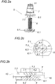
- This gear unit 5 comprises a threaded spindle 6, a spindle nut 7 and a first end stop 8 - as shown in FIG Fig. 1 in conjunction with the Figure 2b recognizable - the threaded spindle 6 is indirectly connected to the membrane 2.1 for its actuation and thus, depending on the position of the membrane 2.1, closes or opens a liquid channel 20 by lifting the membrane from the valve seat 21 on the valve body 22.
- the end stop 8 is formed between two mutually facing stop surfaces 8.1, 8.2 of the threaded spindle 6 and the spindle nut 7 - and limits the stroke of the membrane 2.1 to protect it.
- the need for a comparatively low breakaway torque or a comparatively low breakaway force is ensured by the threaded spindle 6 forming a radially outwardly pointing stop 6.1 with the first stop surface 8.1 and the spindle nut 7 forming a radially inwardly pointing counter-stop 7.1 with the second stop surface 8.2 - as for example after the Figures 2a and 2b evident.
- the stop 6.1 thus extends radially away from the spindle axis 11, i.e. shows a longitudinal extension outward - the course or the longitudinal extension of the counter-stop 7.1 is radially inward from the spindle nut 7, to the spindle axis 11.
- the first and second stop surfaces 8.1, 8.2, which are flat, are arranged normal to the end face 6.2 and 7.2 of the threaded spindle 6 and spindle nut 7, respectively. Furthermore, the surface normals 6.3, 7.3 run tangentially to the spindle axis 11, as shown in FIG Figure 2b in sync with Figure 2c can be seen. The surface normals 6.3, 7.3 are each normal to the spindle axis 11, viewed in the radial direction from the spindle axis 11.
- the valve 1 also has a second gear unit 12, which is provided between the manual drive 4.1 and the spindle nut 7 of the first gear unit 5 and thus lies in front of the first gear unit 5 on the drive side. This is because this second gear unit 12 includes an overload protection 13 for the membrane 2.1.
- the overload protection 13 has two gear wheels 15, 16 coupled via an axial toothing 14 and four spring elements 17.1, 17.2, 17.3, 17.4.
- the spring elements 17.1, 17.2, 17.3, 17.4 press the first gear wheel 15, which is axially displaceable, onto the other second gear wheel 16.
- the axial toothing 14 is asymmetrical.
- the two tooth flanks of each tooth 15.1, 15.2, 16.1 of the axial toothing 14 have a different pitch, i.e. different partial flank angles ⁇ 1, ⁇ 2, which means that the disengagement forces F R1 , F R2 are different depending on the direction of rotation 17 of the manual drive 4.1 .
- the direction of rotation of the valve 1 can thus also be reliably conveyed to a user - and he can thus haptically determine whether the threaded spindle 6 is at the end stop 8.
Landscapes
- Engineering & Computer Science (AREA)
- General Engineering & Computer Science (AREA)
- Mechanical Engineering (AREA)
- Mechanically-Actuated Valves (AREA)
Abstract
Description
- Die Erfindung betrifft ein Ventil, insbesondere Membranventil, mit einem Ventilelement und mit einer mit dem Ventilelement zu dessen Betätigung verbundenen Betätigungseinrichtung, die eine erste Getriebeeinheit mit einer Gewindespindel, einer Spindelmutter und einem Endanschlag aufweist, welcher Endanschlag sich aus mindestens zwei einander zugewandten Anschlagflächen von Gewindespindel (6) und Spindelmutter bildet.
- Ein Ventil, nämlich Membranventil, nach dem Oberbegriff des Anspruchs 1 ist aus der
WO02/093056A1 - Zudem ist der vergleichsweise hohe Kraftaufwand zur Betätigung des Ventils aus der Endposition heraus dahingehend problematisch, dass dieser den Benutzer durchaus veranlassen könnte, in eine inkorrekte Richtung zu drehen. Mit einem Überdrehen der Betätigungseinrichtung und der dadurch gegebenen Gefahr einer mechanischen Überlastung ist zu rechnen - was die Standfestigkeit des Ventils verringert.
- Die Erfindung hat sich daher die Aufgabe gestellt, ausgehend vom eingangs geschilderten Stand der Technik, ein Ventil zur Verfügung zu stellen, welches bei einfacher und sicherer Handhabbarkeit auch eine besonders hohe Standfestigkeit garantieren kann.
- Die Erfindung löst die gestellte Aufgabe durch die Merkmale des Anspruchs 1.
- Ein mechanisch besonders belastbarer Anschlag kann geschaffen werden, indem die Gewindespindel einen radial nach außen weisenden Anschlag mit der ersten Anschlagfläche ausbildet und die Spindelmutter einen radial nach innen weisenden Gegenanschlag mit der zweiten Anschlagfläche ausbildet.
- Sind zudem bei aufeinander aufgelaufenen Anschlagflächen im Endanschlag die einander gegenüberliegenden Stirnflächen von Gewindespindel und Spindelmutter relativ zueinander kontaktfrei, kann beim Betätigen des Ventils eine Losbrechkraft oder ein Losbrechmoment gering gehalten werden - was nicht nur die Handhabung des Ventils erleichtert, sondern auch eine korrekte Betätigung des Ventils sicherstellt. Letztgenanntes wird insbesondere dadurch erreicht, dass ein Benutzer aufgrund einer vergleichsweise niedrigen Losbrechkraft oder niedrigem Losbrechmoment davon abgehalten wird, hohe Kraftbelastung entgegen der, in der jeweiligen Endposition korrekten Betätigungsrichtung aufzubringen. Das erfindungsgemäße Ventil kann sich daher nicht nur durch einfache und sichere Handhabbarkeit, sondern auch durch hohe Standfestigkeit auszeichnen.
- Vorzugsweise ist die erste Anschlagfläche geneigt, insbesondere normal, zur Stirnfläche der Gewindespindel angeordnet, um die Losbrechkraft oder das Losbrechmoment zwischen Gewindespindel und Spindelmutter weiter zu verringern. Zudem schützt eine derart gestaltete erste Anschlagfläche die Gewindespindel gegenüber Zugbelastungen im Endanschlag, was eine Beschädigungsgefahr an der Verzahnung zwischen Gewindespindel und Spindelmutter vermindern bzw. die Standfestigkeit des Ventils erhöhen kann.
- Vorstehend genannter Vorteil ist auch erreichbar, wenn die zweite Anschlagfläche geneigt, insbesondere normal, zur Stirnfläche der Spindelmutter angeordnet ist.
- Die Konstruktionsverhältnisse an der ersten Getriebeeinheit können weiter vereinfacht werden, wenn die Flächennormalen der ersten und zweiten Anschlagfläche tangential zur Spindelachse verlaufen.
- Sind die erste und zweite Anschlagfläche eben ausgebildet, können Singularitäten in der Flächenpressung zwischen den Anschlagflächen vermieden und auch eine konstante Losbrechkraft oder -moment über die Lebensdauer des Ventils ermöglicht werden. Es ist so möglich, für den Benutzer gleichbleibende Bedingungen der Handhabung, insbesondere eine gleichbleibende Haptik bei Betätigung des Ventils sicherzustellen - was zur Verringerung von Fehlbedienung und zur Erhöhung der Lebensdauer des Ventils beiträgt.
- Vorzugsweise weist das Ventil eine Membran als Ventilelement auf.
- Die Konstruktion kann weiter vereinfacht werden, wenn die Gewindespindel mit der Membran zu deren Betätigung verbunden ist.
- Weist die Betätigungseinrichtung einen Antrieb, insbesondere Handantrieb, auf, der die erste Getriebeeinheit antreibt, ist die Betätigungseinrichtung im konstruktiven Aufwand weiter zu vereinfachen.
- Weist das Ventil eine antriebsseitig vor der ersten Getriebeeinheit angeordnete, zweite Getriebeeinheit mit einem Überlastungsschutz auf, kann die erfindungsgemäße erste Getriebeeinheit mit der vergleichsweise geringen Losbrechkraft oder - moment zur konstruktiven Vereinfachung des Überlastungsschutzes beitragen. Dies insbesondere, wenn der Überlastungsschutz zwei über eine Axialverzahnung miteinander gekoppelte Getrieberäder und mindestens ein Federelement umfasst, welches Federelement das erste, axial verschiebbare Getrieberad auf das andere zweite Getrieberad andrückt und damit die Axialverzahnung gegen die, von der Axialverzahnung ausgeübten Ausrückkräfte in Eingriff hält.
- Vorzugsweise sind die Ausrückkräfte durch asymmetrische Axialverzahnung je nach Drehrichtung des Antriebs unterschiedlich hoch, um die in den unterschiedlichen Bewegungsrichtungen, insbesondere Drehrichtungen, am Antrieb, insbesondere Handantrieb, unterschiedlich hohe Begrenzung der Kraft bzw. des Drehmoments zu ermöglichen.
- Vorzugsweise schließt die zweite Getriebeeinheit an die erste Getriebeeinheit an, was für eine kompakte Ausführung des Ventils sorgen kann.
- Dies ist umso mehr erreichbar, wenn das zweite Getrieberad auf der Spindelmutter sitzt.
- In den Figuren ist beispielsweise der Erfindungsgegenstand anhand einer Ausführungsvariante näher dargestellt. Es zeigen
- Fig. 1
- eine teilweise aufgerissene Seitenansicht auf ein Ventil,
- Fig. 2a
- eine Explosionsansicht auf die erste Getriebeeinheit des nach
Fig. 1 dargestellten Ventils, - Fig. 2b
- eine aufgerissene Seitenansicht auf die erste Getriebeeinheit des nach
Fig. 1 dargestellten Ventils, - Fig. 2c
- eine Schnittansicht nach II-II auf die erste Getriebeeinheit des nach
Fig. 1 dargestellten Ventils, - Fig. 3a
- eine Explosionsansicht auf die zweite Getriebeeinheit des nach
Fig. 1 dargestellten Ventils und - Fig. 3b
- eine Detailsicht auf die zweite Getriebeeinheit des nach
Fig. 1 dargestellten Ventils. - Nach
Fig. 1 wird beispielsweise ein Ventil 1 dargestellt, das als Ventilelement 2 eine Membran 2.1 aufweist, welche über eine Betätigungseinrichtung 3 betätigt wird. Hierzu weist die Betätigungseinrichtung 3 einen Handantrieb 4.1 als Antrieb 4 auf, der mit einer ersten Getriebeeinheit 5 verbunden ist. - Diese Getriebeeinheit 5 umfasst ein Gewindespindel 6, eine Spindelmutter 7 und einen ersten Endanschlag 8 - wie anhand der
Fig. 1 in Zusammenschau mit derFig. 2b erkennbar -, wobei die Gewindespindel 6 mit der Membran 2.1 zu deren Betätigung indirekt verbunden ist und damit je nach Lage der Membran 2.1 einen Flüssigkeitskanal 20 sperrt oder öffnet, indem die Membran vom Ventilsitz 21 am Ventilkörper 22 abgehoben wird. - Der Endanschlag 8 bildet sich zwischen zwei einander zugewandten Anschlagflächen 8.1, 8.2 von Gewindespindel 6 und Spindelmutter 7 aus - und beschränkt den Hub der Membran 2.1 zu deren Schutz.
- Der Bedarf eines vergleichsweise geringen Losbrechmoment oder einer vergleichsweise geringen Losbrechkraft werden sichergestellt, indem die Gewindespindel 6 einen radial nach außen weisenden Anschlag 6.1 mit der ersten Anschlagfläche 8.1 ausbildet und die Spindelmutter 7 einen radial nach innen weisenden Gegenanschlag 7.1 mit der zweiten Anschlagfläche 8.2 ausbildet - wie beispielsweise nach den
Figuren 2a und 2b ersichtlich. Der Anschlag 6.1 ist somit von der Spindelachse 11 radial weg verlaufend, zeigt also eine Längserstreckung nach außen - der Verlauf bzw. die Längserstreckung des Gegenanschlags 7.1 ist von der Spindelmutter 7 radial nach innen, zur Spindelachse 11. - Zudem weisen bei aufeinander aufgelaufenen Anschlagflächen 8.1, 8.2 im Endanschlag 8 die einander gegenüberliegenden Stirnflächen 6.2, 7.2 von Gewindespindel 6 und Spindelmutter 7 einen axialen Abstand 10 zueinander auf - was dafür sorgt, dass diese Stirnflächen 6.2, 7.2 zueinander kontaktfrei sind. Damit wird der Flächenkontakt zwischen Gewindespindel 6 und Spindelmutter 7 besonders gering gehalten, wodurch Losbrechmomente reduziert und die Betätigung des Ventils erleichtert wird.
- Die erste und zweite Anschlagfläche 8.1, 8.2, welche eben ausgebildet sind, sind normal zur Stirnfläche 6.2 bzw. 7.2 der Gewindespindel 6 bzw. Spindelmutter 7 angeordnet. Des Weiteren verlaufen die Flächennormalen 6.3, 7.3 tangential zur Spindelachse 11, wie dies nach
Fig. 2b in Zusammenschau mitFig. 2c zu erkennen ist. So stehen die Flächennormalen 6.3, 7.3 in radialer Richtung von der Spindelachse 11 aus gesehen jeweils normal auf die Spindelachse 11. - Das Ventil 1 weist zudem eine zweite Getriebeeinheit 12 auf, die zwischen Handantrieb 4.1 und Spindelmutter 7 der ersten Getriebeeinheit 5 vorgesehen ist und damit antriebsseitig vor der ersten Getriebeeinheit 5 liegt. Dies deshalb, weil diese zweite Getriebeeinheit 12 einen Überlastungsschutz 13 für die Membran 2.1 umfasst.
- Der Überlastungsschutz 13 weist zwei über eine Axialverzahnung 14 gekoppelte Getrieberäder 15, 16 und vier Federelemente 17.1, 17.2, 17.3, 17.4 auf. Die Federelemente 17.1, 17.2, 17.3, 17.4 drücken das erste Getrieberad 15, welches axial verschiebbar ist, auf das andere zweite Getrieberad 16.
- Damit wird die Axialverzahnung 14 gegen, von der Axialverzahnung 14 ausgeübten Ausrückkräfte FR1, FR2 in Eingriff gehalten, ermöglicht aber bei erhöhten Ausrückkräften FR1, FR2, also Kräften welche die Federkraft FF der Federelemente 17.1, 17.2, 17.3, 17.4 übersteigen, ein Durchrutschen der Axialverzahnung 14. Damit kann bei aufeinander aufgelaufenen Anschlagflächen 8.1, 8.2 im Endanschlag 8 eine Überlastung der Wirkverbindung zur Membran 2.1 hin verhindert werden.
- Wie in
Fig. 3b weiter zu erkennen, ist die Axialverzahnung 14 asymmetrisch ausgeführt. So weisen die beiden Zahnflanken jedes Zahns 15.1, 15.2, 16.1 der Axialverzahnung 14 eine unterschiedliche Steigung, also unterschiedliche Teilflankenwinkel α1, α2, auf, was dazu führt, dass die Ausrückkräfte FR1, FR2 je nach Drehrichtung 17 des Handantriebs 4.1 unterschiedlich hoch ausfallen. Einem Benutzer kann damit am Ventil 1 auch die Drehrichtung zuverlässig vermittelt werden - und dieser so haptisch feststellen, ob sich die Gewindespindel 6 am Endanschlag 8 befindet.
Claims (12)
- Ventil, insbesondere Membranventil, mit einem Ventilelement (2) und mit einer mit dem Ventilelement (2) zu dessen Betätigung verbundenen Betätigungseinrichtung (3), die eine erste Getriebeeinheit (5) mit einer Gewindespindel (6), einer Spindelmutter (7) und einem Endanschlag (8) aufweist, welcher Endanschlag (8) sich aus mindestens zwei einander zugewandten Anschlagflächen (8.1, 8.2) von Gewindespindel (6) und Spindelmutter (7) bildet, dadurch gekennzeichnet, dass die Gewindespindel (6) einen radial nach außen weisenden Anschlag (6.1) mit der ersten Anschlagfläche (8.1) ausbildet und die Spindelmutter (7) einen radial nach innen weisenden Gegenanschlag (7.2) mit der zweiten Anschlagfläche (8.2) ausbildet, wobei bei aufeinander aufgelaufenen Anschlagflächen (8.1, 8.2) im Endanschlag (8) die einander gegenüberliegenden Stirnflächen (6.2, 7.2) von Gewindespindel (6) und Spindelmutter (7) zueinander kontaktfrei sind.
- Ventil nach Anspruch 1, dadurch gekennzeichnet, dass die erste Anschlagfläche (8.1) geneigt, insbesondere normal, zur Stirnfläche (6.2) der Gewindespindel (6) angeordnet ist.
- Ventil nach Anspruch 1 oder 2, dadurch gekennzeichnet, dass die zweite Anschlagfläche (8.2) geneigt, insbesondere normal, zur Stirnfläche (7.2) der Spindelmutter (7) angeordnet ist.
- Ventil nach Anspruch 1, 2 oder 3, dadurch gekennzeichnet, dass die Flächennormalen (6.3, 7.3) der ersten und zweiten Anschlagfläche (8.1, 8.2) tangential zur Spindelachse (11) verlaufen.
- Ventil nach einem der Ansprüche 1 bis 4, dadurch gekennzeichnet, dass die erste und zweite Anschlagfläche (8.1, 8.2) eben ausgebildet sind.
- Ventil nach einem der Ansprüche 1 bis 5, dadurch gekennzeichnet, dass das Ventil eine Membran (2.1) als Ventilelement (2) aufweist.
- Ventil nach Anspruch 6, dadurch gekennzeichnet, dass die Gewindespindel (6) mit der Membran (2.1) zu deren Betätigung verbunden ist.
- Ventil nach einem der Ansprüche 1 bis 7, dadurch gekennzeichnet, dass die Betätigungseinrichtung (3) einen Antrieb (4), insbesondere Handantrieb (4.1), aufweist, der die erste Getriebeeinheit (5) antreibt.
- Ventil nach einem der Ansprüche 1 bis 8, dadurch gekennzeichnet, dass das Ventil (1) eine antriebsseitig vor der ersten Getriebeeinheit (5) angeordnete, zweite Getriebeeinheit (12) mit einem Überlastungsschutz (13) aufweist, wobei der Überlastungsschutz (13) zwei über eine Axialverzahnung (14) miteinander gekoppelte Getrieberäder (15, 16) und mindestens ein Federelement (17.1, 17.2, 17.3, 17.4) umfasst, welches Federelement (17.1, 17.2, 17.3, 17.4) das erste, axial verschiebbare Getrieberad (15) auf das andere zweite Getrieberad (16) andrückt und damit die Axialverzahnung (14) gegen die, von der Axialverzahnung (14) ausgeübten Ausrücckräfte (FR1, FR2) in Eingriff hält.
- Ventil nach Anspruch 9, dadurch gekennzeichnet, dass durch asymmetrische Axialverzahnung (14) die Ausrückkräfte (FR1, FR2) je nach Drehrichtung (17) des Antriebs (4) unterschiedlich hoch sind.
- Ventil nach Anspruch 9 oder 10, dadurch gekennzeichnet, dass die zweite Getriebeeinheit (12) an die erste Getriebeeinheit (5) anschließt.
- Ventil nach Anspruch 11, dadurch gekennzeichnet, dass das zweite Getrieberad (16) auf der Spindelmutter (7) sitzt.
Priority Applications (2)
| Application Number | Priority Date | Filing Date | Title |
|---|---|---|---|
| EP19185075.9A EP3763969B1 (de) | 2019-07-08 | 2019-07-08 | Ventil |
| ES19185075T ES2963298T3 (es) | 2019-07-08 | 2019-07-08 | Válvula |
Applications Claiming Priority (1)
| Application Number | Priority Date | Filing Date | Title |
|---|---|---|---|
| EP19185075.9A EP3763969B1 (de) | 2019-07-08 | 2019-07-08 | Ventil |
Publications (2)
| Publication Number | Publication Date |
|---|---|
| EP3763969A1 true EP3763969A1 (de) | 2021-01-13 |
| EP3763969B1 EP3763969B1 (de) | 2023-08-23 |
Family
ID=67220664
Family Applications (1)
| Application Number | Title | Priority Date | Filing Date |
|---|---|---|---|
| EP19185075.9A Active EP3763969B1 (de) | 2019-07-08 | 2019-07-08 | Ventil |
Country Status (2)
| Country | Link |
|---|---|
| EP (1) | EP3763969B1 (de) |
| ES (1) | ES2963298T3 (de) |
Cited By (1)
| Publication number | Priority date | Publication date | Assignee | Title |
|---|---|---|---|---|
| CN115231462A (zh) * | 2021-04-23 | 2022-10-25 | 德国日本电产电机与驱动器有限公司 | 用于电动高度调整的执行器和高度可调台 |
Citations (6)
| Publication number | Priority date | Publication date | Assignee | Title |
|---|---|---|---|---|
| US3029660A (en) * | 1959-11-05 | 1962-04-17 | Beaver Prec Products Inc | Ball screw with stop means |
| US5851003A (en) * | 1996-05-31 | 1998-12-22 | Fujikoki Corporation | Motor operated valve |
| WO2002093056A1 (de) | 2001-05-15 | 2002-11-21 | Danfoss Trata D.O.O. | Ventilantrieb |
| EP2278199A1 (de) * | 2009-07-23 | 2011-01-26 | Miodrag Stanic | Verbessertes Absperrventil |
| US20110315906A1 (en) * | 2010-06-25 | 2011-12-29 | Fujikoki Corporation | Female screw member, motor operated valve using the same, and method for producing female screw member for motor operated valve |
| DE202014100716U1 (de) * | 2014-02-18 | 2014-03-10 | Bürkert Werke GmbH | Handbetätigtes Ventil |
-
2019
- 2019-07-08 ES ES19185075T patent/ES2963298T3/es active Active
- 2019-07-08 EP EP19185075.9A patent/EP3763969B1/de active Active
Patent Citations (6)
| Publication number | Priority date | Publication date | Assignee | Title |
|---|---|---|---|---|
| US3029660A (en) * | 1959-11-05 | 1962-04-17 | Beaver Prec Products Inc | Ball screw with stop means |
| US5851003A (en) * | 1996-05-31 | 1998-12-22 | Fujikoki Corporation | Motor operated valve |
| WO2002093056A1 (de) | 2001-05-15 | 2002-11-21 | Danfoss Trata D.O.O. | Ventilantrieb |
| EP2278199A1 (de) * | 2009-07-23 | 2011-01-26 | Miodrag Stanic | Verbessertes Absperrventil |
| US20110315906A1 (en) * | 2010-06-25 | 2011-12-29 | Fujikoki Corporation | Female screw member, motor operated valve using the same, and method for producing female screw member for motor operated valve |
| DE202014100716U1 (de) * | 2014-02-18 | 2014-03-10 | Bürkert Werke GmbH | Handbetätigtes Ventil |
Cited By (2)
| Publication number | Priority date | Publication date | Assignee | Title |
|---|---|---|---|---|
| CN115231462A (zh) * | 2021-04-23 | 2022-10-25 | 德国日本电产电机与驱动器有限公司 | 用于电动高度调整的执行器和高度可调台 |
| CN115231462B (zh) * | 2021-04-23 | 2024-03-19 | 德国日本电产电机与驱动器有限公司 | 用于电动高度调整的执行器和高度可调台 |
Also Published As
| Publication number | Publication date |
|---|---|
| ES2963298T3 (es) | 2024-03-26 |
| EP3763969B1 (de) | 2023-08-23 |
Similar Documents
| Publication | Publication Date | Title |
|---|---|---|
| EP1853436B1 (de) | Stirnverzahnung für eine antreibbare radnabe | |
| DE60032892T2 (de) | Schnellösemutter | |
| EP2649329B1 (de) | Schraube mit einem schraubenkopf, einem schraubenschaft und einem konischen, gewellten flansch | |
| DE102010011820A1 (de) | Planetenwälzgewindetrieb | |
| DE202009002062U1 (de) | Drehmoment-Stecknuss | |
| DE102014110439A1 (de) | Rotor für einen Elektromotor | |
| DE19648581B4 (de) | Scheibenbremse mit Feststellbremsfunktion | |
| EP1298353A2 (de) | Zahnradpaarung und deren Verwendung | |
| EP0208979B1 (de) | Überlastsicherung | |
| EP3763969B1 (de) | Ventil | |
| WO2012072394A1 (de) | Aktuator | |
| EP3143294B1 (de) | Vorrichtung zum sichern eines spannelements gegen ungewolltes lösen | |
| DE102008005454B4 (de) | Scheibenbremse mit Rutschkupplung für die Nachstelleinrichtung | |
| DE102022106921A1 (de) | Doppelkupplungsgetriebe mit Verschleißnachstellung | |
| EP2333354B1 (de) | Schraub- oder Nietverbindung | |
| EP2459905A1 (de) | Dichtring und anordnung mit einem dichtring | |
| EP1945957B1 (de) | Vorrichtung zum sichern einer welle-nabe-verbindung zweier wellen | |
| DE4102420A1 (de) | Handwerkzeugmaschine, insbesondere winkelschleifmaschine | |
| DE2736329C3 (de) | Überlastkupplung | |
| EP2052900B1 (de) | Getriebeanordnung | |
| DE2917331C3 (de) | Direktantrieb für Tiefbohrmeißel o.dgl. in einem Rohrloch arbeitende Werkzeuge | |
| EP2292945B1 (de) | Scheibenbremse mit Rutschkupplung für die Nachstelleinrichtung | |
| EP0009544B1 (de) | Überlastkupplung | |
| DE102021125484B4 (de) | Schubgestänge für einen Linearaktuator und Linearaktuator mit einem Schubgestänge | |
| DE3030878A1 (de) | Kupplungsausruecklager |
Legal Events
| Date | Code | Title | Description |
|---|---|---|---|
| PUAI | Public reference made under article 153(3) epc to a published international application that has entered the european phase |
Free format text: ORIGINAL CODE: 0009012 |
|
| STAA | Information on the status of an ep patent application or granted ep patent |
Free format text: STATUS: THE APPLICATION HAS BEEN PUBLISHED |
|
| AK | Designated contracting states |
Kind code of ref document: A1 Designated state(s): AL AT BE BG CH CY CZ DE DK EE ES FI FR GB GR HR HU IE IS IT LI LT LU LV MC MK MT NL NO PL PT RO RS SE SI SK SM TR |
|
| AX | Request for extension of the european patent |
Extension state: BA ME |
|
| STAA | Information on the status of an ep patent application or granted ep patent |
Free format text: STATUS: REQUEST FOR EXAMINATION WAS MADE |
|
| 17P | Request for examination filed |
Effective date: 20210713 |
|
| RBV | Designated contracting states (corrected) |
Designated state(s): AL AT BE BG CH CY CZ DE DK EE ES FI FR GB GR HR HU IE IS IT LI LT LU LV MC MK MT NL NO PL PT RO RS SE SI SK SM TR |
|
| GRAP | Despatch of communication of intention to grant a patent |
Free format text: ORIGINAL CODE: EPIDOSNIGR1 |
|
| RIC1 | Information provided on ipc code assigned before grant |
Ipc: F16D 43/202 20060101ALN20221215BHEP Ipc: F16K 7/12 20060101ALN20221215BHEP Ipc: F16K 31/50 20060101ALI20221215BHEP Ipc: F16H 25/20 20060101AFI20221215BHEP |
|
| STAA | Information on the status of an ep patent application or granted ep patent |
Free format text: STATUS: GRANT OF PATENT IS INTENDED |
|
| INTG | Intention to grant announced |
Effective date: 20230119 |
|
| GRAJ | Information related to disapproval of communication of intention to grant by the applicant or resumption of examination proceedings by the epo deleted |
Free format text: ORIGINAL CODE: EPIDOSDIGR1 |
|
| STAA | Information on the status of an ep patent application or granted ep patent |
Free format text: STATUS: REQUEST FOR EXAMINATION WAS MADE |
|
| GRAS | Grant fee paid |
Free format text: ORIGINAL CODE: EPIDOSNIGR3 |
|
| STAA | Information on the status of an ep patent application or granted ep patent |
Free format text: STATUS: GRANT OF PATENT IS INTENDED |
|
| GRAP | Despatch of communication of intention to grant a patent |
Free format text: ORIGINAL CODE: EPIDOSNIGR1 |
|
| INTC | Intention to grant announced (deleted) | ||
| P01 | Opt-out of the competence of the unified patent court (upc) registered |
Effective date: 20230526 |
|
| RIC1 | Information provided on ipc code assigned before grant |
Ipc: F16D 43/202 20060101ALN20230601BHEP Ipc: F16K 7/12 20060101ALN20230601BHEP Ipc: F16K 31/50 20060101ALI20230601BHEP Ipc: F16H 25/20 20060101AFI20230601BHEP |
|
| INTG | Intention to grant announced |
Effective date: 20230613 |
|
| GRAA | (expected) grant |
Free format text: ORIGINAL CODE: 0009210 |
|
| STAA | Information on the status of an ep patent application or granted ep patent |
Free format text: STATUS: THE PATENT HAS BEEN GRANTED |
|
| AK | Designated contracting states |
Kind code of ref document: B1 Designated state(s): AL AT BE BG CH CY CZ DE DK EE ES FI FR GB GR HR HU IE IS IT LI LT LU LV MC MK MT NL NO PL PT RO RS SE SI SK SM TR |
|
| REG | Reference to a national code |
Ref country code: GB Ref legal event code: FG4D Free format text: NOT ENGLISH |
|
| REG | Reference to a national code |
Ref country code: CH Ref legal event code: EP |
|
| REG | Reference to a national code |
Ref country code: IE Ref legal event code: FG4D Free format text: LANGUAGE OF EP DOCUMENT: GERMAN |
|
| REG | Reference to a national code |
Ref country code: DE Ref legal event code: R096 Ref document number: 502019009024 Country of ref document: DE |
|
| REG | Reference to a national code |
Ref country code: LT Ref legal event code: MG9D |
|
| REG | Reference to a national code |
Ref country code: NL Ref legal event code: MP Effective date: 20230823 |
|
| PG25 | Lapsed in a contracting state [announced via postgrant information from national office to epo] |
Ref country code: GR Free format text: LAPSE BECAUSE OF FAILURE TO SUBMIT A TRANSLATION OF THE DESCRIPTION OR TO PAY THE FEE WITHIN THE PRESCRIBED TIME-LIMIT Effective date: 20231124 |
|
| PG25 | Lapsed in a contracting state [announced via postgrant information from national office to epo] |
Ref country code: IS Free format text: LAPSE BECAUSE OF FAILURE TO SUBMIT A TRANSLATION OF THE DESCRIPTION OR TO PAY THE FEE WITHIN THE PRESCRIBED TIME-LIMIT Effective date: 20231223 |
|
| PG25 | Lapsed in a contracting state [announced via postgrant information from national office to epo] |
Ref country code: SE Free format text: LAPSE BECAUSE OF FAILURE TO SUBMIT A TRANSLATION OF THE DESCRIPTION OR TO PAY THE FEE WITHIN THE PRESCRIBED TIME-LIMIT Effective date: 20230823 Ref country code: RS Free format text: LAPSE BECAUSE OF FAILURE TO SUBMIT A TRANSLATION OF THE DESCRIPTION OR TO PAY THE FEE WITHIN THE PRESCRIBED TIME-LIMIT Effective date: 20230823 Ref country code: PT Free format text: LAPSE BECAUSE OF FAILURE TO SUBMIT A TRANSLATION OF THE DESCRIPTION OR TO PAY THE FEE WITHIN THE PRESCRIBED TIME-LIMIT Effective date: 20231226 Ref country code: NO Free format text: LAPSE BECAUSE OF FAILURE TO SUBMIT A TRANSLATION OF THE DESCRIPTION OR TO PAY THE FEE WITHIN THE PRESCRIBED TIME-LIMIT Effective date: 20231123 Ref country code: NL Free format text: LAPSE BECAUSE OF FAILURE TO SUBMIT A TRANSLATION OF THE DESCRIPTION OR TO PAY THE FEE WITHIN THE PRESCRIBED TIME-LIMIT Effective date: 20230823 Ref country code: LV Free format text: LAPSE BECAUSE OF FAILURE TO SUBMIT A TRANSLATION OF THE DESCRIPTION OR TO PAY THE FEE WITHIN THE PRESCRIBED TIME-LIMIT Effective date: 20230823 Ref country code: LT Free format text: LAPSE BECAUSE OF FAILURE TO SUBMIT A TRANSLATION OF THE DESCRIPTION OR TO PAY THE FEE WITHIN THE PRESCRIBED TIME-LIMIT Effective date: 20230823 Ref country code: IS Free format text: LAPSE BECAUSE OF FAILURE TO SUBMIT A TRANSLATION OF THE DESCRIPTION OR TO PAY THE FEE WITHIN THE PRESCRIBED TIME-LIMIT Effective date: 20231223 Ref country code: HR Free format text: LAPSE BECAUSE OF FAILURE TO SUBMIT A TRANSLATION OF THE DESCRIPTION OR TO PAY THE FEE WITHIN THE PRESCRIBED TIME-LIMIT Effective date: 20230823 Ref country code: GR Free format text: LAPSE BECAUSE OF FAILURE TO SUBMIT A TRANSLATION OF THE DESCRIPTION OR TO PAY THE FEE WITHIN THE PRESCRIBED TIME-LIMIT Effective date: 20231124 Ref country code: FI Free format text: LAPSE BECAUSE OF FAILURE TO SUBMIT A TRANSLATION OF THE DESCRIPTION OR TO PAY THE FEE WITHIN THE PRESCRIBED TIME-LIMIT Effective date: 20230823 |
|
| PG25 | Lapsed in a contracting state [announced via postgrant information from national office to epo] |
Ref country code: PL Free format text: LAPSE BECAUSE OF FAILURE TO SUBMIT A TRANSLATION OF THE DESCRIPTION OR TO PAY THE FEE WITHIN THE PRESCRIBED TIME-LIMIT Effective date: 20230823 |
|
| REG | Reference to a national code |
Ref country code: ES Ref legal event code: FG2A Ref document number: 2963298 Country of ref document: ES Kind code of ref document: T3 Effective date: 20240326 |
|
| PG25 | Lapsed in a contracting state [announced via postgrant information from national office to epo] |
Ref country code: SM Free format text: LAPSE BECAUSE OF FAILURE TO SUBMIT A TRANSLATION OF THE DESCRIPTION OR TO PAY THE FEE WITHIN THE PRESCRIBED TIME-LIMIT Effective date: 20230823 Ref country code: RO Free format text: LAPSE BECAUSE OF FAILURE TO SUBMIT A TRANSLATION OF THE DESCRIPTION OR TO PAY THE FEE WITHIN THE PRESCRIBED TIME-LIMIT Effective date: 20230823 Ref country code: EE Free format text: LAPSE BECAUSE OF FAILURE TO SUBMIT A TRANSLATION OF THE DESCRIPTION OR TO PAY THE FEE WITHIN THE PRESCRIBED TIME-LIMIT Effective date: 20230823 Ref country code: DK Free format text: LAPSE BECAUSE OF FAILURE TO SUBMIT A TRANSLATION OF THE DESCRIPTION OR TO PAY THE FEE WITHIN THE PRESCRIBED TIME-LIMIT Effective date: 20230823 Ref country code: CZ Free format text: LAPSE BECAUSE OF FAILURE TO SUBMIT A TRANSLATION OF THE DESCRIPTION OR TO PAY THE FEE WITHIN THE PRESCRIBED TIME-LIMIT Effective date: 20230823 Ref country code: SK Free format text: LAPSE BECAUSE OF FAILURE TO SUBMIT A TRANSLATION OF THE DESCRIPTION OR TO PAY THE FEE WITHIN THE PRESCRIBED TIME-LIMIT Effective date: 20230823 |
|
| REG | Reference to a national code |
Ref country code: DE Ref legal event code: R097 Ref document number: 502019009024 Country of ref document: DE |
|
| PLBE | No opposition filed within time limit |
Free format text: ORIGINAL CODE: 0009261 |
|
| STAA | Information on the status of an ep patent application or granted ep patent |
Free format text: STATUS: NO OPPOSITION FILED WITHIN TIME LIMIT |
|
| 26N | No opposition filed |
Effective date: 20240524 |
|
| PG25 | Lapsed in a contracting state [announced via postgrant information from national office to epo] |
Ref country code: SI Free format text: LAPSE BECAUSE OF FAILURE TO SUBMIT A TRANSLATION OF THE DESCRIPTION OR TO PAY THE FEE WITHIN THE PRESCRIBED TIME-LIMIT Effective date: 20230823 |
|
| PG25 | Lapsed in a contracting state [announced via postgrant information from national office to epo] |
Ref country code: BG Free format text: LAPSE BECAUSE OF FAILURE TO SUBMIT A TRANSLATION OF THE DESCRIPTION OR TO PAY THE FEE WITHIN THE PRESCRIBED TIME-LIMIT Effective date: 20230823 |
|
| PG25 | Lapsed in a contracting state [announced via postgrant information from national office to epo] |
Ref country code: BG Free format text: LAPSE BECAUSE OF FAILURE TO SUBMIT A TRANSLATION OF THE DESCRIPTION OR TO PAY THE FEE WITHIN THE PRESCRIBED TIME-LIMIT Effective date: 20230823 |
|
| PG25 | Lapsed in a contracting state [announced via postgrant information from national office to epo] |
Ref country code: MC Free format text: LAPSE BECAUSE OF FAILURE TO SUBMIT A TRANSLATION OF THE DESCRIPTION OR TO PAY THE FEE WITHIN THE PRESCRIBED TIME-LIMIT Effective date: 20230823 |
|
| PG25 | Lapsed in a contracting state [announced via postgrant information from national office to epo] |
Ref country code: LU Free format text: LAPSE BECAUSE OF NON-PAYMENT OF DUE FEES Effective date: 20240708 |
|
| PG25 | Lapsed in a contracting state [announced via postgrant information from national office to epo] |
Ref country code: LU Free format text: LAPSE BECAUSE OF NON-PAYMENT OF DUE FEES Effective date: 20240708 |
|
| PG25 | Lapsed in a contracting state [announced via postgrant information from national office to epo] |
Ref country code: BE Free format text: LAPSE BECAUSE OF NON-PAYMENT OF DUE FEES Effective date: 20240731 |
|
| REG | Reference to a national code |
Ref country code: BE Ref legal event code: MM Effective date: 20240731 |
|
| PG25 | Lapsed in a contracting state [announced via postgrant information from national office to epo] |
Ref country code: IE Free format text: LAPSE BECAUSE OF NON-PAYMENT OF DUE FEES Effective date: 20240708 |
|
| PGFP | Annual fee paid to national office [announced via postgrant information from national office to epo] |
Ref country code: ES Payment date: 20250819 Year of fee payment: 7 |
|
| PGFP | Annual fee paid to national office [announced via postgrant information from national office to epo] |
Ref country code: DE Payment date: 20250722 Year of fee payment: 7 |
|
| PGFP | Annual fee paid to national office [announced via postgrant information from national office to epo] |
Ref country code: IT Payment date: 20250731 Year of fee payment: 7 |
|
| PGFP | Annual fee paid to national office [announced via postgrant information from national office to epo] |
Ref country code: GB Payment date: 20250718 Year of fee payment: 7 |
|
| PGFP | Annual fee paid to national office [announced via postgrant information from national office to epo] |
Ref country code: FR Payment date: 20250723 Year of fee payment: 7 Ref country code: AT Payment date: 20250721 Year of fee payment: 7 |
|
| PGFP | Annual fee paid to national office [announced via postgrant information from national office to epo] |
Ref country code: CH Payment date: 20250801 Year of fee payment: 7 |
|
| PG25 | Lapsed in a contracting state [announced via postgrant information from national office to epo] |
Ref country code: CY Free format text: LAPSE BECAUSE OF FAILURE TO SUBMIT A TRANSLATION OF THE DESCRIPTION OR TO PAY THE FEE WITHIN THE PRESCRIBED TIME-LIMIT; INVALID AB INITIO Effective date: 20190708 |
|
| PG25 | Lapsed in a contracting state [announced via postgrant information from national office to epo] |
Ref country code: HU Free format text: LAPSE BECAUSE OF FAILURE TO SUBMIT A TRANSLATION OF THE DESCRIPTION OR TO PAY THE FEE WITHIN THE PRESCRIBED TIME-LIMIT; INVALID AB INITIO Effective date: 20190708 |