EP3764199B1 - Procédés, appareils et programmes informatiques pour commander une interface utilisateur - Google Patents
Procédés, appareils et programmes informatiques pour commander une interface utilisateur Download PDFInfo
- Publication number
- EP3764199B1 EP3764199B1 EP19186015.4A EP19186015A EP3764199B1 EP 3764199 B1 EP3764199 B1 EP 3764199B1 EP 19186015 A EP19186015 A EP 19186015A EP 3764199 B1 EP3764199 B1 EP 3764199B1
- Authority
- EP
- European Patent Office
- Prior art keywords
- hand
- user interface
- movement
- distance
- distance sensor
- Prior art date
- Legal status (The legal status is an assumption and is not a legal conclusion. Google has not performed a legal analysis and makes no representation as to the accuracy of the status listed.)
- Active
Links
Images





Classifications
-
- G—PHYSICS
- G06—COMPUTING OR CALCULATING; COUNTING
- G06F—ELECTRIC DIGITAL DATA PROCESSING
- G06F3/00—Input arrangements for transferring data to be processed into a form capable of being handled by the computer; Output arrangements for transferring data from processing unit to output unit, e.g. interface arrangements
- G06F3/01—Input arrangements or combined input and output arrangements for interaction between user and computer
- G06F3/017—Gesture based interaction, e.g. based on a set of recognized hand gestures
-
- G—PHYSICS
- G06—COMPUTING OR CALCULATING; COUNTING
- G06F—ELECTRIC DIGITAL DATA PROCESSING
- G06F3/00—Input arrangements for transferring data to be processed into a form capable of being handled by the computer; Output arrangements for transferring data from processing unit to output unit, e.g. interface arrangements
- G06F3/01—Input arrangements or combined input and output arrangements for interaction between user and computer
- G06F3/03—Arrangements for converting the position or the displacement of a member into a coded form
- G06F3/0304—Detection arrangements using opto-electronic means
-
- G—PHYSICS
- G06—COMPUTING OR CALCULATING; COUNTING
- G06F—ELECTRIC DIGITAL DATA PROCESSING
- G06F3/00—Input arrangements for transferring data to be processed into a form capable of being handled by the computer; Output arrangements for transferring data from processing unit to output unit, e.g. interface arrangements
- G06F3/01—Input arrangements or combined input and output arrangements for interaction between user and computer
- G06F3/03—Arrangements for converting the position or the displacement of a member into a coded form
- G06F3/041—Digitisers, e.g. for touch screens or touch pads, characterised by the transducing means
- G06F3/042—Digitisers, e.g. for touch screens or touch pads, characterised by the transducing means by opto-electronic means
- G06F3/0425—Digitisers, e.g. for touch screens or touch pads, characterised by the transducing means by opto-electronic means using a single imaging device like a video camera for tracking the absolute position of a single or a plurality of objects with respect to an imaged reference surface, e.g. video camera imaging a display or a projection screen, a table or a wall surface, on which a computer generated image is displayed or projected
Definitions
- Examples relate to methods, apparatuses and computer programs for controlling a user interface, more specifically, but not exclusively, to concepts for controlling a user interface in which the user interface is projected onto a hand (or another part of the user's body).
- buttons or levers have been used to operate machines, such as simple push buttons. In order to be able to operate more complex systems, these buttons were gradually combined into so-called keyboards, as they are still used today to operate computers. But other input devices, such as mice, are also used to operate user interfaces.
- touchscreens touch-sensitive display devices
- the user can directly manipulate the user interface with a finger or a stylus (i.e. a pen for operating touchscreens).
- these input options all have the disadvantage that their implementations require a certain amount of space or have unfavorable ergonomics: For example, keyboards and mice require a large area on which they can be accommodated, while touchscreens are in many cases ergonomically questionable, for example in screens that are arranged almost vertically in front of the user.
- US patent application US 2013/086531 A1 relates to a command issuing device, which uses a projection device to project a user interface on the fingers of the user. The user can tap the respective fingers with another finger to control the user interface.
- JP 2018 073170 A a user interface is projected onto a palm of a user. A user interface element may be selected moving the hand relative to the user interface. The selection is confirmed by forming a fist.
- US patent application US 2012/1 13223 A1 relates to user interaction in augmented reality. Similar to the previous examples, a user interface is projected onto the hand of a user and controlled by bending the digit on which a menu item of the user interface is projected.
- JP 2012 089079 A a user interface is projected onto a hand of an occupant of a vehicle. Different menu items may be selected by swiping the hand horizontally. The selection is confirmed by pinching two fingers together.
- a rotational movement of the hand is determined and used to control the user interface.
- Embodiments of the present disclosure are based on the insight that a hand can be used to both display the user interface and (at the same time) control the user interface by detecting a movement of the hand.
- the user interface is projected onto the hand of a user.
- the movement of the hand is recorded via a distance sensor, i.e. the movement of the hand that is orthogonal to a depth axis between the distance sensor and the hand.
- movements along the depth axis can be detected, enabling intuitive control of the user interface.
- another part of the body such as an arm/forearm or a leg/shank, may be used both as projection surface and entity controlling the user interface.
- the movement of the other body part may be recorded and used to control the user interface.
- Embodiments of the present disclosure provide a method for controlling a user interface.
- the method comprises projecting a user interface onto a hand of a user.
- the method comprises determining three-dimensional distance information of a distance between the hand and a distance sensor.
- the method comprises controlling the user interface based on the movement of at least parts of the hand.
- the user interface is controlled based on the rotational movement.
- the method may comprise determining a movement of the hand orthogonal to a depth axis between the distance sensor and the hand.
- the user interface may be controlled based on the movement of the hand orthogonal to the depth axis. This allows intuitive control of the user interface via movements in an x/y plane being orthogonal to the z-axis/depth axis.
- the movement of the hand orthogonal to the depth axis may be used to select one of a plurality of choices.
- movements along two axes are possible in the x/y plane, choices along these two axes can be selected efficiently.
- the selection of the choice may be visualized by a selection field in the user interface.
- the movement of the hand orthogonal to the depth axis may control the user interface such that the selection field is shifted in accordance with the movement of the hand so that a position of the selection field on the hand remains substantially constant and the selection field shifts relative to the plurality of choices.
- the movement of the hand orthogonal to the depth axis may control the user interface such that the plurality of choices are shifted according to the movement of the hand so that a position of the plurality of choices on the hand remains substantially constant and the plurality of choices are shifted relative to the selection field.
- Determining the movement of at least parts of the hand comprises determining a rotational, and optionally a curvature movement, of at least parts of the hand.
- the user interface is controlled based on the rotational movement, and optionally based on the curvature movement.
- the determination of rotational or curvature movement can be enabled or improved by determining a hand movement in the depth axis.
- the rotational or curvature movements can be used to control the user interface.
- At least two choices of the user interface may be projected onto at least two fingers. One of the at least two choices may be selected if the corresponding finger is bent. This enables a direct relationship between the choice and the part of the hand that is to be pressed to select the choice.
- one of the at least two choices is selected if the corresponding finger may be touched by another finger on which no choice is projected.
- the corresponding finger may be touched with a thumb of the hand or with a finger of another hand.
- determining the movement of at least portions of the hand comprises determining a movement of the entire hand along a depth axis between the hand and the distance sensor.
- the user interface may be controlled based on the movement of the entire hand along the depth axis. This may enable further gestures.
- a movement of the entire hand along the depth axis in the direction of the distance sensor may change or activate an element of the user interface.
- the movement of the entire hand along the depth axis (e.g. toward the distance sensor) may correspond to the "click" of a mouse.
- Determining the three-dimensional distance information may further comprise determining three-dimensional distance information of a distance between a further hand and the distance sensor.
- the method may comprise determining a movement of the further hand based on the three-dimensional distance information of the distance between the further hand and the distance sensor.
- the controlling of the user interface may be further based on the movement of the further hand. An intuitive selection can be made by using the further hand.
- the three-dimensional distance information of the distance between the hand and the distance sensor comprises a plurality of distance values for different portions of the hand.
- the movement of at least parts of the hand may be determined based on the plurality of distance values. This enables or improves the detection of the movement of individual parts of the hand.
- the method may further comprise providing an acoustic feedback based on the controlling of the user interface. This may provide the user with an improved feedback on the abstract operation of the user interface by hand.
- the method comprises providing a control signal to the user interface to effect the controlling of the user interface.
- the controlling of the user interface may be visualized by the user interface.
- the control signal may be used to visualize and apply the interaction between the hand and the user interface.
- the method may further comprise determining whether a palm or a back of the hand faces the distance sensor, and activating the user interface if the palm is brought to face the distance sensor by a rotational movement of the hand.
- a hand rotation can be used to activate the user interface by intuitively switching between a hand side that is only used passively and a side of the hand that is actively used.
- the method may comprise detecting whether the hand is opened or closed based on the movement of at least parts of the hand.
- the method may comprise activating the user interface if the hand being opened is detected and deactivating the user interface if the hand being closed is detected.
- the method illustrated above refers to the overall system of distance sensor, projection device, processing module and user interface.
- the method is illustrated with respect to an execution of the method by a processing module, such as a processor.
- the method may further comprise providing a display signal to a projection device to cause the projection of the user interface onto the hand of a user.
- the method may further comprise receiving a distance measurement signal from a distance sensor, wherein the three-dimensional distance information of the distance between the hand and the distance sensor is determined based on the distance measurement signal.
- the method may further comprise providing a control signal to the user interface to effect the controlling of the user interface based on the movement of at least parts of the hand.
- Embodiments of the present disclosure provide a computer program having a program code for performing the further method, when the computer program is executed on a computer, a processor, or a programmable hardware component.
- Embodiments of the present disclosure provide an apparatus for controlling a user interface.
- the apparatus comprises at least one interface for communicating with a projection device and with a distance sensor.
- the apparatus comprises a processing module configured to provide a display signal to the projection device to cause a projection of the user interface onto a hand of a user.
- the processing module is configured to receive a distance measurement signal from the distance sensor.
- the processing module is configured to determine three-dimensional distance information of a distance between the hand and the distance sensor based on the distance measurement signal.
- the processing module is configured to determine a movement of at least parts of the hand based on the three-dimensional distance information.
- Determining the movement of at least parts of the hand comprises determining a rotational movement of the hand around a rotation axis of the hand when the hand is rotated by rotation of the wrist and/or upper arm.
- the processing module is configured to provide a control signal to the user interface to effect the controlling of the user interface based on the movement of at least parts of the hand.
- the user interface is controlled based on the rotational movement.
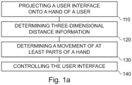
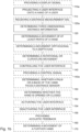
- Figs. 1a to 1c show flow charts of embodiments of a method for controlling a user interface.
- the method of Figures 1a and 1b relate to an overall system in which a projection device, a distance sensor and a processing module are combined to perform the method.
- the method comprises projecting 110 a user interface onto a hand of a user (or more general, a body part of the user).
- the method comprises determining 120 three-dimensional distance information of a distance between the hand (or body part) and a distance sensor.
- the method comprises determining 130 a movement of at least parts of the hand (or body part) based on the three-dimensional distance information.
- the method comprises controlling 140 the user interface based on the movement of at least parts of the hand (or body part).
- the method may be performed by a system comprising the projection device, the distance sensor and the processing module.
- the method comprises providing 110a a display signal to a projection device to cause a projection of the user interface onto a hand (or body part) of a user.
- the method comprises receiving 120a a distance measurement signal from a distance sensor.
- the method comprises determining 120 three-dimensional distance information of a distance between the hand (or body part) and the distance sensor based on the distance measurement signal.
- the method further comprises Determining 130 a movement of at least parts of the hand (or body part) based on the three-dimensional distance information.
- the method comprises providing 140a a control signal to the user interface to effect the controlling of the user interface based on the movement of at least parts of the hand (or body part).
- the method of Fig. 1c represents an implementation of the method of Figs. 1a and 1b , in which the processing steps are carried out by the processing module, for example in conjunction with at least one interface. Accordingly, characteristics and additional features of the method are Fig. 1a and 1b may also apply to the method of Fig. 1c .
- Fig. 1d shows a block diagram of an embodiment of an apparatus for controlling a user interface 20.
- the apparatus 10 comprises at least one interface 12 for communicating with a projection device 16 and with a distance sensor 18.
- the apparatus 10 comprises a processing module 14 that is coupled to the at least one interface 12.
- the processing module 14 may be configured to perform the method of Fig. 1c , e.g. in conjunction with the at least one interface 12.
- the pressing module 14 is configured to provide a display signal to the projection device 16 to cause a projection of the user interface onto a hand (or body part) of a user.
- the processing module is configured to receive a distance measurement signal from the distance sensor 18.
- the processing module 14 is configured to determine three-dimensional distance information of a distance between the hand (or body part) and the distance sensor based on the distance measurement signal.
- the processing module 14 is configured to determine a movement of at least parts of the hand (or body part) based on the three-dimensional distance information.
- the processing module is configured to provide a control signal to the user interface to effect the controlling of the user interface based on the movement of at least parts of the hand (or body part).
- Fig. 1d further shows a system comprising the projection device 16, the distance sensor 18 and the apparatus 10.
- Embodiments relate to with methods, computer programs, and devices for controlling a user interface.
- the user interface is a visual user interface, i.e. it may be perceived by the user's eyes, and it is modifiable, i.e. the user interface changes, for example based on an input by the user or based on events of an operating system.
- the method may comprise providing 110a a display signal to the projection device to cause (i.e. effect) a projection of the user interface onto the hand of the user.
- This display signal may include, for example, video and/or control information adapted to project the display signal on the user interface.
- the projection device may be located above the user's hand, such as in a floor lamp, ceiling lamp, ceiling of a room (e.g. of an office, living room, public space, restaurant etc.) or vehicle (e.g. a car, a train car or a bus), or on a wall or electronic device such as a monitor.
- the user interface may be projected by the projection device (from above) onto a surface of the user's hand.
- the distance sensor may also be placed above the user's hand, such as the projection unit/parallel to the projection unit. Alternatively, the distance sensor may be located below the user's hand.
- the projection of the user interface onto the user's hand may depend on the distance between the user's hand and the projection device.
- the user interface has a fixed target size that may be adjusted based on the distance between the user's hand and the projection device, for example to achieve a given absolute size (e.g. 8x10 cm) or a given size relative to the hand (e.g. 50%/60%/70%/80% of an area of the back of the hand or the inside of the hand) of the user interface.
- the projection of the user interface onto the user's hand may be adjusted based on the distance to ensure that the user interface is "sharp" on the hand, for example by adjusting the focus distance, or by correcting for perspective distortions that occur due to the shape or orientation of the hand.
- the projection may use dynamic projection mapping based on the three-dimensional distance information.
- dynamic projection mapping a projection is dynamically mapped onto a non-rigid surface, e.g. based on an adjustment of the projection based of the shape, deformation and/or orientation of the surface (i.e. the hand).
- the method may comprise adjusting the projection of the user interface based on the three-dimensional distance information, for example to achieve a given absolute size or a given size relative to the hand, to focus the projection, or to adjust or correct a perspective of the projection.
- the focusing of the projection may be achieved by changing the focal distance based on the three-dimensional distance information. This may e.g. be foregone if a focus-free laser projection of is used, e.g. if the projector is a focus-free laser projector.
- the absolute or relative size of the user interface may be changed by changing the image angle based on three-dimensional distance information.
- the perspective of the projection may be adjusted or corrected by performing a perspective transformation (or even a freeform transformation) that takes into account a shape and/or orientation of the hand, e.g. based on the three-dimensional distance information.
- the projection may be adjusted orthogonally to the depth axis based on a movement of the hand, i.e. a target direction of the projection may be adjusted orthogonally to the depth axis depending on the movement of the hand, e.g. based on the three-dimensional distance information.
- the position of the hand of the user may change while the user interface is manipulated. For example, while the user may stay substantially in the same place, e.g. on a seat of a vehicle or on a seat at a desk, the position of his hand may change during the projection of the user interface on the hand of the user. Accordingly, to project the user interface onto the hand of the user, a position of the hand may be tracked.
- the method may comprise determining a position of the hand based on the three-dimensional distance information. Based on the position of the hand, the projection may be adjusted. In other words, the method may comprise adjusting the projection based on the position of the hand, e.g. so that the user interface is projected onto the hand if the position of the hand is changed.
- the projection device may be a wide-angle projection device, e.g. having a projection angle of more than 30°, that projects a wider projection onto a general area the hand of the user may be located in.
- the projection may be adjusted by adjusting an area of the wider projection that is used for the user interface, based on the position of the hand.
- a narrow-angle projection device e.g. having a projection angle of at most 30°, may be used, that projects a smaller projection onto the hand.
- the projection may be adjusted by tilting the projection device or by tilting a mirror reflecting the projection based on the position of the hand (e.g. as shown in Fig. 2a ).
- the method comprises determining 120 the three-dimensional distance information of the distance between the hand and the distance sensor. For example, to determine the three-dimensional distance information, a distance measurement signal may be received (i.e. obtained) from the distance sensor. In other words, the method may comprise receiving 120a the distance measurement signal from the distance sensor.
- the three-dimensional distance information may be determined based on the distance measurement signal.
- the distance sensor may be a so-called Time-of-Flight (ToF) based distance sensor, such as a time-of-flight-based distance sensor that is based on modulated light or a time-of-flight-based distance sensor that is based on ultrasound.
- ToF Time-of-Flight
- the distance sensor may be an optical distance sensor, such as a time-of-flight distance sensor based on modulated light, a distance sensor based on structured light, or a LIDAR-based distance sensor (Light Detection and Ranging).
- the distance measurement signal may include raw data or pre-processed data from the corresponding distance sensor; determining the three-dimensional distance information may comprise processing the raw data or pre-processed sensor data.
- the distance information is three-dimensional, i.e. the distance information distinguishes not only distances between the distance sensor and the hand in the depth axis, but also orthogonally to the depth axis. If, for example, the depth axis (also z-axis) is defined by the axis between the hand and the distance sensor, a lateral plane defined by an x-axis and a y-axis spans orthogonal to the depth axis. Within the lateral plane, which is orthogonal to the depth axis, the distance information distinguishes between different positions on the lateral plane, i.e. the movement of the hand is not only determined relative to the depth axis, but also orthogonal to it.
- the three-dimensional distance information of the distance between the hand and the distance sensor may comprise a plurality of distance values for different portions of the hand.
- the movement of at least parts of the hand may be determined 130 based on the plurality of distance values.
- the plurality of distance values may be used not only to capture the movement of the hand "as a whole" relative to the depth axis, but also to individually determine the movement of the portions/parts of the hand.
- determining 120 the three-dimensional distance information may further comprise determining three-dimensional distance information of a distance between the further hand and the distance sensor.
- the three-dimensional distance information of the distance between the further hand and the distance sensor may be determined similar to the three-dimensional distance information of the distance between the hand (on which the user interface is projected) and the distance sensor.
- the method comprises determining 130 a movement of at least parts of the hand based on the three-dimensional distance information.
- the movement of at least parts of the hand may be caused by a movement of the entire hand in the lateral plane or along the depth axis, by a rotation of the hand, by a curvature movement (of parts) of the hand.
- the movement of at least parts of the hand along the depth axis includes not only a movement of the entire hand, but (any) movement of the hand. For example, when the hand is curved, parts of the hand are moved along the depth axis (as well as orthogonally to it), while other parts remain rigid.
- the entire hand (apart from the rotation axis) is moved along the depth axis (in motion around the rotation axis) and the lateral plane.
- the rotation axis may correspond to the natural rotation axis of the hand (i.e. the hand is rotated by rotation of the wrist and/or upper arm).
- the method may comprise determining 170 a movement of the further hand based on the three-dimensional distance information of the distance between the further hand and the distance sensor. The movement of the further hand may be determined similar to the movement of the hand.
- the method may comprise determining 132 a movement of the hand orthogonal to the depth axis between the distance sensor and the hand.
- the projection device and the distance sensor are arranged in close proximity, so that the depth axis between the distance sensor and the hand substantially corresponds to the depth axis between the projection device and the hand.
- the "depth axis between the distance sensor and the hand" may also be interpreted as "depth axis between the projection device and the hand”.
- the depth axis may be an axis that forms the center of the projection of the user interface.
- the movement of the hand orthogonal to the depth axis may be defined as a lateral movement, i.e.
- the movement of the hand orthogonal to the depth axis may occur on the lateral plane (a x/y-plane) that spans orthogonal to the depth axis.
- the movement of the hand orthogonal to the depth axis may correspond to a movement of the (entire) hand on the lateral plane.
- the movement of the hand orthogonal to the depth axis may be determined by tracking the hand within the three-dimensional distance information, i.e. by tracking a movement of the entire hand on the lateral plane.
- determining the movement of at least parts of the hand may comprise determining 134 a rotational or curvature movement of at least parts of the hand.
- determining the rotational or curvature motion may involve tracking a distance of a plurality of portions of the hand to detect a rotational or curvature motion of the plurality of motions (such as about an axis of rotation or relative to a base of the hand).
- a three-dimensional distance value may be determined for each section. Over several points in time, the respective three-dimensional distance value may be compared with the corresponding distance value of a previous point in time in order to determine a difference between the distance values.
- a calculation may be performed to determine whether the three-dimensional distance values change in a way caused by rotation or curvature of the hand (or caused by movement of the entire hand along one of the axes).
- a plane may be formed over the plurality of distance values (e.g. by interpolation), and the rotation of the hand may be determined by detecting a change in the position of the plane.
- the plane may be divided into several portions of the plane. If a position or orientation of the portion of the plane changes, a curvature movement may be determined.
- the plurality of distance values may be used as input values for a neural network (i.e. a machine-learning model), wherein the neural network is trained to determine the rotational movement and/or curvature movement of the hand based on distance values.
- a movement of the entire hand along the depth axis may also be determined, such as an up or down movement of the hand (if the distance sensor is located below or above the hand).
- determining 130 the movement of at least portions of the hand may comprise determining 136 a movement of the entire hand along the depth axis, e.g. the depth axis between the hand and the distance sensor or between the hand and the projection device.
- an average value of the plurality of distance values may be calculated.
- the movement of the entire hand along the depth axis may be determined based on the average value of the plurality of distance values.
- the movement of the entire hand along the depth axis along the depth axis may be registered (i.e. taken into account) if it exceeds a distance threshold value within a specified period of time (e.g. more than 1 cm within 0.5 s).
- a distance threshold value e.g. more than 1 cm within 0.5 s.
- the movement of the entire hand along the depth axis along the depth axis may be registered (i.e. taken into account) if there is no (or only a small) rotational movement and/or no (or only a small) curvature movement.
- the method comprises controlling 140 the user interface based on the movement of at least parts of the hand.
- the user interface may be controlled based on the movement orthogonal to the depth axis, based on rotational or curvature movement and/or based on the movement of the entire hand along the depth axis. Additionally, the controlling 140 of the user interface may further be based on the movement of the further hand.
- the method may comprise providing 140a a control signal to the user interface to effect the controlling of the user interface.
- the user interface may, for example, be generated by an operating system of the processing module.
- the control signal may be provided to and interpreted by the operating system.
- the user interface may be controlled based on the control signal.
- a corresponding visual representation of the user interface may be generated, which is projected onto the user's hand via the projection device.
- the display signal may be generated based on the controlling of the user interface and the display signal may be provided to the projection device.
- the projection device may be a projector such as a video projector such as an LCD-based projector (Liquid Crystal Display) or a DLP-based projector (Digital Light Processing).
- the projection device may be compact. Accordingly, the projection device may be a mini projector or a pico projector.
- the projector may be a narrow-field projector, and the projection may be projected on the hand via a rotatable mirror, or the projector may be a wide-angle projector and areas outside the projection of the user interface may be blacked out.
- the controlling of the user interface may be visualized through the user interface.
- the user interface may include one or more descriptions (i.e. labels), one or more graphical elements, one or more choices, one or more selection fields and/or one or more visual indicators.
- choices may be visualized as text or in the form of icons (i.e. pictograms).
- Descriptions may be visualized as text.
- Visual indicators, such as selection fields, may be visualized by colored frames or by frames highlighted by their light intensity. The selection of a choice may be visualized by a selection field in the user interface.
- the visualizations may be displayed by the projection of the user interface on the hand.
- the particular movement may be used to control the user interface. It may be assumed that the movement is converted into a control instruction (of the control signal) for the user interface, i.e. an abstract movement is processed and the control instruction is generated based on the movement (possibly context-dependent). Both the movements and the effects on the user interface are described abstractly, but it should always be understood that the respective movement is detected, a corresponding control instruction based on the detected movement is generated, this control instruction being suitable for controlling the user interface accordingly.
- the user interface may be controlled based on the movement of the hand orthogonal to the depth axis (i.e. the movement of the hand in the lateral plane).
- the movement of the hand in the lateral plane to move a first item of the user interface relative to one or more second items, e.g. by either keeping the first item at a fixed position relative to the hand (i.e. hand-fixed) and the one or more second items at a fixed position relative to a global coordinate space (e.g. world-fixed or coordinate system-fixed), or by keeping the first item at a fixed position relative to the global coordinate space and the one or more second items at a fixed position relative to the hand.
- a paradigm may be used to select one of a plurality of choices.
- the movement of the hand orthogonal to the depth axis may be used to select one of a plurality of choices.
- the first item may be a selection field and the one or more second items may be a plurality of choices.
- the selection of the choice may be visualized by a selection field in the user interface.
- the first item i.e. the selection field
- the one or more second items i.e. the plurality of choices
- the movement of the hand orthogonal to the depth axis may control the user interface such (i.e. may effect the controlling of the user interface such) that the selection field is shifted in accordance with the movement of the hand, so that a position of the selection field on the hand remains substantially constant (i.e.
- the first item i.e. the selection field
- the one or more second items i.e. the plurality of choices
- the movement of the hand orthogonal to the depth axis may control the user interface such (i.e. may effect the controlling of the user interface such) that the plurality of choices are shifted according to the movement of the hand so that a position of the plurality of choices on the hand remains substantially constant (i.e.
- the selection field may be a "magnetic" selection field, i.e. the selection field may remain with one choice of the plurality of choices until a threshold is crossed, after which the selection field crosses over to the next choice.
- a linear movement of the selection field may be used.
- the selection field might e.g. bounce back or be compressed to indicate the edge of the user interface (an affordance for indicating the limits of the user interface to the user).
- the curvature or rotation movement of the hand may be used to control the user interface.
- a choice may be made from a variety of choices.
- a curvature of a finger for example, may be used to control the user interface.
- at least two choices of the user interface may be projected onto at least two fingers.
- the at least two choices may be projected onto at least two fingers of the group of an index finger, a middle finger, a ring finger and a small finger.
- One of at least two choices may be selected if the corresponding finger is bent (i.e. if a curvature of the corresponding finger has been determined via the three-dimensional distance information).
- the choice may be selected, for example, if the bending of the corresponding finger exceeds a predefined degree of curvature.
- one of the at least two choices may be selected if the corresponding finger is touched by another finger on which no choice is projected, e.g. another finger of the same hand (e.g. the thumb) or a finger of the further hand. If the choice is deemed selected, this may be indicated by a visual indication, e.g. by highlighting the corresponding choice in the projection of the user interface. A choice may be highlighted using bigger fonts, brighter or different colors, a higher color intensity, an animation, and/or a border surrounding the choice (or a combination thereof). This visual indication may also be used in other embodiments.
- the user interface may be controlled based on the movement of the entire hand along (i.e. substantially parallel to) the depth axis. For example, by moving the entire hand along the depth axis in the direction of the distance sensor, an element of the user interface may be activated, e.g. a selection may be confirmed. For example, a selection may be confirmed by thrusting the hand upwards along the depth axis (e.g. in the direction of the distance sensor).
- an element of the user interface may be changed, such as a selection of the plurality of choices, or a numeric value may be changed gradually or according to a specified interval (depending on the distance of the entire hand from the distance sensor).
- predefined gestures may also be used to perform predefined actions, such as activating or deactivating the user interface.
- One way is to detect whether the inside or outside of the hand is turned upwards.
- the method may comprise determining 150 whether a palm or a back of the hand faces the distance sensor.
- the method may comprise activating 154 the user interface if the palm is brought to face the distance sensor by a rotational movement of the hand.
- the method may comprise deactivating 156 the user interface if the back of the hand is brought to face the distance sensor by a rotational movement of the hand.
- the activation/deactivation may be based on whether the hand is opened or closed.
- the method may comprise detecting 152 whether the hand is opened or closed based on the movement of at least parts of the hand.
- the method may comprise activating 154 the user interface if the hand being opened is detected and deactivating 156 the user interface if the hand being closed is detected.
- the method may further comprise providing 160 an acoustic feedback based on the controlling of the user interface (e.g. via an acoustic output device), e.g. by providing an audio signal to the acoustic output device.
- the at least one interface 12 may be coupled to an acoustic output device, i.e. the system may comprise the acoustic output device.
- the acoustic feedback may, for example, take place each time the user interface is controlled, or (only) when a choice is selected or confirmed. For example, a (discreet) acoustic hint may be output.
- the method may comprise projecting a user interface onto a body part of a user.
- the method may comprise determining three-dimensional distance information of a distance between the body part and a distance sensor.
- the method may comprise determining a movement of at least parts of the body part based on the three-dimensional distance information.
- the method may comprise controlling the user interface based on the movement of at least parts of the body part.
- the body part may be an arm (e.g. a forearm) or a leg or shank of the user. Additional aspects that were previously described in connection with the hand of the user, may also be applied more generally to the body part of the user, e.g. the arm (e.g. a forearm) or a leg or shank of the user.
- the at least one interface 12 may correspond to one or more inputs and/or outputs for receiving and/or transmitting information, which may be in digital (bit) values according to a specified code, within a module, between modules or between modules of different entities.
- the at least one interface 12 may comprise interface circuitry configured to receive and/or transmit information.
- the processing module 14 may be implemented using one or more processing units, one or more processing devices, any means for processing, such as a processor, a computer or a programmable hardware component being operable with accordingly adapted software.
- a processor any means for processing
- the described function of the processing module 14 may as well be implemented in software, which is then executed on one or more programmable hardware components.
- Such hardware components may comprise a general purpose processor, a Digital Signal Processor (DSP), a micro-controller, etc.
- DSP Digital Signal Processor
- Embodiments of the present disclosure provide a protected User Interface (UI).
- the projected user interface may be targeted for use in a vehicle, e.g. by for rear seat passengers or in public transportation vehicles, but is not limited for such use.
- the projected user interface may be used in architecture, such as buildings, homes, offices, restaurants etc.)
- the projected UI might comprise no physical UI / mechatronics.
- the user interface may be at hand, an inspiring, intuitive and modern UI and may feature one-handed controllability.
- state of the art illumination of the space may be used.
- the projection may follow the hand. This can either be achieved by (physically) adjusting a direction of a narrow-angle projection being output from a projector, as shown in Fig. 2a , or by using a wide-angle projection which is only partially used, as shown in Fig. 2b .
- Figs. 2a and 2b show schematic diagrams of embodiments of a projection device for projecting a user interface.
- a smaller projector i.e. projection device 16 is used (e.g. a narrow-angle projector), together with a x/y rotatable mirror 210, to enable multiple projection areas 220; 230 for different positions of the hand 200, which can be used by rotating the mirror 210.
- a sensor e.g. a distance sensor
- the projection user interface (the sun icon) follows the movement of the hand 200 digitally (pixel-based) and mechanically (mirror-based).
- a wide-angle projector 16 is used to create a larger projection field 240, which might only be partially used at a position of the hand 200.
- a wide-angle projector 16 might require no mechanics, as it follows the hand (only) digitally (pixel-based), and might use simpler mapping software. Due to the large projection field, a larger projector (for the same brightness) may be required, and a lower resolution may be achieved.
- a sensor e.g. a distance sensor 18 is used to track the movement of the hand 200.
- Various functionality may be controlled and/or shown via the user interface.
- a genre may be selected, a volume may be changed or tracks may be skipped.
- a navigation section an estimated time of arrival may be shown.
- a climate control section a temperature may be adjusted.
- a fragrance section a type and intensity of the fragrance may be adjusted.
- a seat adjustment section a back rest angle and a seat position may be adjusted.
- a light section a reading light or an ambient light may be activated or adjusted.
- the sections entertainment, navigation, climate control, fragrance, seat adjustment and light may also be controlled indirectly via a mood section, in which a mood or intensity may be selected.
- a call may be accepted or rejected, or a recent contact may be selected.
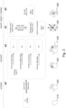
- Fig. 3 shows an overview of a hand movement-based control of a user interface.
- a user-initiated user interface is shown.
- the hand When the hand is closed 310, the user interface is in a standby state.
- the hand To activate user interface, the hand may be opened 320, to deactivate the user interface, the hand may be closed 310.
- an acoustic feedback may be provided.
- the hand Once the hand is open, it may be used to navigate among the sections (e.g. among choices of a plurality of choices), where the last functionality or a context-specific functionality (such as changing volume after the music changes substantially, accessing navigation in case of a traffic jam etc.) may pre-selected after activation.
- the choices may be projected on different fingers of the hand, and they may be activated by bending the respective finger, touching the finger with the thumb of the same hand 330 or touching the finger with a finger of another hand 340.
- function F1 may be selected
- function F2 may be selected
- function F3 may be selected
- function F4 may be selected.
- an acoustic feedback may be provided.
- a movement 350 of the hand along the x-,y- or z-axis may be used to adjust a setting, select a choice or confirm a setting or choice. For example, by lifting the hand (a movement along the z-axis/depth-axis) a value may be increased or an item may be pressed, by lowering the hand (along the z-axis/depth-axis) the value may be decreased or the item may be released.
- an x/y-movement i.e. orthogonal to the z-axis/depth axis
- an item may be selected.
- an item By tapping an item with the other hand 360, an item may be started/executed. After each performed action, an acoustic feedback may be provided.
- Fig. 4 shows a schematic diagram of an activation of a user interface. This is an example of a system-initiated UI/notification.
- a symbol e.g. a pictogram or an animation, such as sparkling particles
- the closed hand/back side of the hand or alternatively on the arm rest.
- any user may move his/her hand to the projection of the symbol, thereby taking control of the user interface.
- an acoustic notification may be provided.
- a description of the event (“incoming call / first name last name") 422 and options that are available (accept 424a/424b and decline 426a/426b) may be projected on the palm of the hand (424a/426a) or on two fingers (424b/426b).
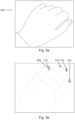
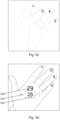
- Figs. 5a to 5j show schematic drawings of a hand movement-based control of a user interface.
- various states of the user interface are shown.
- the hand is closed (left symbol has solid lines) or opened (right symbol has solid lines).
- the projection of the user interface is shown 500.
- the hand is closed, which deactivates the user interface.
- the user interface is activated on the hand (as seen in figs 5b to 5i ).
- a plurality of choices 510 to 514 are projected on the fingers of the hand (starting from the index finger to the little finger: Favorites, Entertainment, climate Control and Seat Adjustment).
- the section favorites is selected by touching the index finger with the thumb.
- the different sections/domains are indicated by icons. Icons, for example for different domains can be projected on the hand, for example on the fingertips. They can be selected by touching the icons on the fingertips with the thumb (or a finger of the other hand).
- the entertainment section is selected by touching the middle finger with the thumb.
- a plurality of choices of the entertainment section are shown, e.g. volume 526 or skip track 524.
- a currently selected choice is highlighted by selection field 522.
- Selecting several items or buttons (i.e. choices) can be achieved with a horizontal movement, for example sideways (as shown) or front and back.
- a "magnetic snap cursor" (the selection field 522) may be absolutely fixated to the coordinate system and the UI items may be fixated to the hand moved across the UI item.
- the cursor "snaps" on one of the three items (skip forward, volume, skip backward). For example, in Fig.
- the hand is moved to the left, so the items/choices move to the left, and the selection field remains fixed to the coordinate system.
- Fig. Sg the hand is moved to the right, choices/items move to the right, and selection field remains fixed to the coordinate system.
- a 2D movement in x/y direction can be done to achieve a "non-snappy", smooth mouse cursor like control. Confirming a selection (like a "click") can be done with vertical movement.
- all UI items can be touched, shifted, selected and clicked like on a touchscreen with a finger of the other hand. Every action can be supported by a unique sound, so-called earcons.
- Fig. 5g the climate control section selected by touching the ring finger with the thumb.
- the climate control section in Fig. 5h , the selection field 528 is shown over the plurality of choices representing different temperatures.
- a vertical hand movement can be executed.
- Visual hints for example a scale, can be projected on the hand for discoverability and affordability.
- the seat adjustment section is selected by touching the little finger with the thumb.
- Fig. 5j shows an indication of availability, e.g. a notification, on the closed hand.
- Hints visual, acoustical
- Hints can provide UI discoverability and affordability.
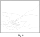
- Fig. 6 shows a further schematic drawing of a hand movement-based control of a user interface.
- a call notification is projected onto the hand, comprising a projection of a red receiver and a projection of a green receiver, which may be selected by tapping on them with the other hand.
- the projected user interface or the controlling of the projected user interface may comprise one or more additional optional features corresponding to one or more aspects of the proposed concept or one or more examples described above or below.
- Examples may further be or relate to a computer program having a program code for performing one or more of the above methods, when the computer program is executed on a computer or processor. Steps, operations or processes of various above-described methods may be performed by programmed computers or processors. Examples may also cover program storage devices such as digital data storage media, which are machine, processor or computer readable and encode machine-executable, processor-executable or computer-executable programs of instructions. The instructions perform or cause performing some or all of the acts of the above-described methods.
- the program storage devices may comprise or be, for instance, digital memories, magnetic storage media such as magnetic disks and magnetic tapes, hard drives, or optically readable digital data storage media.
- FIG. 1 may also cover computers, processors or control units programmed to perform the acts of the above-described methods or (field) programmable logic arrays ((F)PLAs) or (field) programmable gate arrays ((F)PGAs), programmed to perform the acts of the above-described methods.
- a functional block denoted as "means for " performing a certain function may refer to a circuit that is configured to perform a certain function.
- a "means for s.th.” may be implemented as a "means configured to s.th.”, such as a device or a circuit configured to the respective task.
- Functions of various elements shown in the figures may be implemented in the form of dedicated hardware, such as “a signal provider”, “a signal processing unit”, “a processor”, “a controller”, etc. as well as hardware capable of executing software in association with appropriate software.
- a processor the functions may be provided by a single dedicated processor, by a single shared processor, or by a plurality of individual processors, some of which or all of which may be shared.
- processor or “controller” is by far not limited to hardware exclusively capable of executing software, but may include digital signal processor (DSP) hardware, network processor, application specific integrated circuit (ASIC), field programmable gate array (FPGA), read only memory (ROM) for storing software, random access memory (RAM), and nonvolatile storage.
- DSP digital signal processor
- ASIC application specific integrated circuit
- FPGA field programmable gate array
- ROM read only memory
- RAM random access memory
- nonvolatile storage Other hardware, conventional and/or custom, may also be included.
- a block diagram may, for instance, illustrate a high-level circuit diagram implementing the principles of the disclosure.
- a flow chart, a flow diagram, a state transition diagram, a pseudo code, and the like may represent various processes, operations or steps, which may, for instance, be substantially represented in computer readable medium and so executed by a computer or processor, whether or not such computer or processor is explicitly shown.
- Methods disclosed in the specification or in the claims may be implemented by a device having means for performing each of the respective acts of these methods.
Landscapes
- Engineering & Computer Science (AREA)
- General Engineering & Computer Science (AREA)
- Theoretical Computer Science (AREA)
- Human Computer Interaction (AREA)
- Physics & Mathematics (AREA)
- General Physics & Mathematics (AREA)
- Multimedia (AREA)
- User Interface Of Digital Computer (AREA)
- Position Input By Displaying (AREA)
Claims (18)
- Procédé pour commander une interface utilisateur, le procédé comprenant les étapes consistant à :projeter (110) une interface utilisateur sur une main d'un utilisateur ;déterminer (120) une information de distance tridimensionnelle d'une distance entre la main et un capteur de distance ;déterminer (130) un mouvement d'au moins certaines parties de la main sur la base de l'information de distance tridimensionnelle, la détermination du mouvement d'au moins certaines parties de la main comprenant la détermination (134) d'un mouvement de rotation de la main autour d'un axe de rotation de la main lorsque la main tourne par rotation du poignet et/ou de l'avant-bras ; etcommander (140) l'interface utilisateur sur la base du mouvement d'au moins certaines parties de la main, l'interface utilisateur étant commandée sur la base du mouvement de rotation.
- Procédé selon la revendication 1, le procédé comprenant la détermination (132) d'un mouvement de la main orthogonal à un axe de profondeur entre le capteur de distance et la main, l'interface utilisateur étant commandée sur la base du mouvement de la main orthogonal à l'axe de profondeur.
- Procédé selon la revendication 2, dans lequel le mouvement de la main orthogonal à l'axe de profondeur est utilisé pour sélectionner un choix parmi une pluralité de choix.
- Procédé selon la revendication 3, dans lequel la sélection du choix est visualisée par un champ de sélection dans l'interface utilisateur, dans lequel le mouvement de la main orthogonal à l'axe de profondeur commande l'interface utilisateur de telle façon que le champ de sélection se déplace en fonction du mouvement de la main afin qu'une position du champ de sélection sur la main reste sensiblement constante et que le champ de sélection se déplace par rapport à la pluralité de choix.
- Procédé selon la revendication 3, dans lequel la sélection du choix est visualisée par un champ de sélection dans l'interface utilisateur, dans lequel le mouvement de la main orthogonal à l'axe de profondeur commande l'interface utilisateur de telle façon que la pluralité de choix se déplace en fonction du mouvement de la main afin qu'une position de la pluralité de choix sur la main reste sensiblement constante et que la pluralité de choix se déplace par rapport au champ de sélection.
- Procédé selon l'une des revendications 1 à 3, dans lequel la détermination du mouvement d'au moins certaines parties de la main comprend la détermination (134) d'un mouvement de courbure d'au moins certaines parties de la main, dans lequel l'interface utilisateur est commandée sur la base du mouvement de courbure.
- Procédé selon la revendication 6, dans lequel au moins deux choix de l'interface utilisateur sont projetés (110) sur au moins deux doigts, dans lequel un des au moins deux choix est sélectionné si le doigt correspondant est plié.
- Procédé selon la revendication 6, dans lequel un des au moins deux choix est sélectionné si le doigt correspondant est touché par un autre doigt sur lequel aucun choix n'est projeté.
- Procédé selon l'une des revendications 1 à 8, dans lequel la détermination (130) du mouvement d'au moins certaines parties de la main comprend la détermination (136) d'un mouvement de l'ensemble de la main le long d'un axe de profondeur entre la main et le capteur de distance, dans lequel l'interface utilisateur est commandée sur la base du mouvement de l'ensemble de la main le long de l'axe de profondeur.
- Procédé selon la revendication 9, dans lequel un mouvement de l'ensemble de la main le long de l'axe de profondeur dans la direction du capteur de distance modifie ou active un élément de l'interface utilisateur.
- Procédé selon l'une des revendications 1 à 10, dans lequel la détermination (120) de l'information de distance tridimensionnelle comprend également la détermination d'une information de distance tridimensionnelle d'une distance entre une autre main et le capteur de distance, le procédé comprenant la détermination (170) d'un mouvement de l'autre main sur la base de l'information de distance tridimensionnelle de la distance entre l'autre main et le capteur de distance, dans lequel la commande (140) de l'interface utilisateur s'effectue également sur la base du mouvement de l'autre main.
- Procédé selon l'une des revendications 1 à 11, dans lequel l'information de distance tridimensionnelle de la distance entre la main et le capteur de distance comprend une pluralité de valeurs de distance relatives à différentes parties de la main, dans lequel le mouvement d'au moins certaines parties de la main est déterminé (130) sur la base de la pluralité de valeurs de distance.
- Procédé selon l'une des revendications 1 à 12, comprenant également la fourniture (160) d'un retour acoustique sur la base de la commande de l'interface utilisateur.
- Procédé selon l'une des revendications 1 à 13, le procédé comprenant la fourniture (140a) d'un signal de commande à l'interface utilisateur pour effectuer la commande de l'interface utilisateur, dans lequel la commande de l'interface utilisateur est visualisée par l'interface utilisateur.
- Procédé selon la revendication 1, le procédé comprenant l'étape consistant à déterminer (150) si c'est la paume ou le dos de la main qui fait face au capteur de distance, et à activer (154) l'interface utilisateur si la paume est amenée face au capteur de distance par un mouvement de rotation de la main, et/ou le procédé comprenant l'étape consistant à déterminer (152) si la main est ouverte ou fermée sur la base du mouvement d'au moins certaines parties de la main, le procédé comprenant l'activation (154) de l'interface utilisateur s'il est détecté que la main est ouverte et la désactivation (156) de l'interface utilisateur s'il est détecté que la main est fermée.
- Procédé selon l'une des revendications 1 à 15, le procédé comprenant également la fourniture (110a) d'un signal d'affichage à un dispositif de projection pour causer la projection de l'interface utilisateur sur la main d'un utilisateur, la réception (120a) d'un signal de mesure de distance en provenance d'un capteur de distance, l'information de distance tridimensionnelle de la distance entre la main et le capteur de distance étant déterminée (120) sur la base du signal de mesure de distance, et la fourniture (140a) d'un signal de commande à l'interface utilisateur pour effectuer la commande de l'interface utilisateur sur la base du mouvement d'au moins certaines parties de la main.
- Programme d'ordinateur ayant un code de programme pour réaliser le procédé selon la revendication 16, lorsque le programme d'ordinateur s'exécute sur un ordinateur, un processeur ou un composant matériel programmable.
- Appareil (10) pour commander une interface utilisateur (20), l'appareil (10) comprenant :au moins une interface (12) pour communiquer avec un dispositif de projection (16) et avec un capteur de distance (18) ; etun module de traitement (14), configuré pour :fournir un signal d'affichage au dispositif de projection (16) pour causer une projection de l'interface utilisateur sur une main d'un utilisateur,recevoir un signal de mesure de distance en provenance du capteur de distance (18),déterminer une information de distance tridimensionnelle d'une distance entre la main et le capteur de distance sur la base du signal de mesure de distance,déterminer un mouvement d'au moins certaines parties de la main sur la base de l'information de distance tridimensionnelle, la détermination du mouvement d'au moins certaines parties de la main comprenant la détermination d'un mouvement de rotation de la main autour d'un axe de rotation de la main lorsque la main tourne par rotation du poignet et/ou de l'avant-bras ; etfournir un signal de commande à l'interface utilisateur pour effectuer la commande de l'interface utilisateur sur la base du mouvement d'au moins certaines parties de la main, l'interface utilisateur étant commandée sur la base du mouvement de rotation.
Priority Applications (1)
| Application Number | Priority Date | Filing Date | Title |
|---|---|---|---|
| EP19186015.4A EP3764199B1 (fr) | 2019-07-12 | 2019-07-12 | Procédés, appareils et programmes informatiques pour commander une interface utilisateur |
Applications Claiming Priority (1)
| Application Number | Priority Date | Filing Date | Title |
|---|---|---|---|
| EP19186015.4A EP3764199B1 (fr) | 2019-07-12 | 2019-07-12 | Procédés, appareils et programmes informatiques pour commander une interface utilisateur |
Publications (2)
| Publication Number | Publication Date |
|---|---|
| EP3764199A1 EP3764199A1 (fr) | 2021-01-13 |
| EP3764199B1 true EP3764199B1 (fr) | 2024-11-20 |
Family
ID=67262161
Family Applications (1)
| Application Number | Title | Priority Date | Filing Date |
|---|---|---|---|
| EP19186015.4A Active EP3764199B1 (fr) | 2019-07-12 | 2019-07-12 | Procédés, appareils et programmes informatiques pour commander une interface utilisateur |
Country Status (1)
| Country | Link |
|---|---|
| EP (1) | EP3764199B1 (fr) |
Families Citing this family (1)
| Publication number | Priority date | Publication date | Assignee | Title |
|---|---|---|---|---|
| US20250103144A1 (en) * | 2023-09-26 | 2025-03-27 | Humane, Inc. | Gestures for navigating and selecting items using a laser projected ephemeral user interface |
Family Cites Families (4)
| Publication number | Priority date | Publication date | Assignee | Title |
|---|---|---|---|---|
| JP5271331B2 (ja) * | 2010-10-22 | 2013-08-21 | 株式会社ホンダアクセス | 車両用入出力装置 |
| US20120113223A1 (en) * | 2010-11-05 | 2012-05-10 | Microsoft Corporation | User Interaction in Augmented Reality |
| JP5624530B2 (ja) * | 2011-09-29 | 2014-11-12 | 株式会社東芝 | コマンド発行装置、方法及びプログラム |
| JP6210466B1 (ja) * | 2016-10-31 | 2017-10-11 | パナソニックIpマネジメント株式会社 | 情報入力装置 |
-
2019
- 2019-07-12 EP EP19186015.4A patent/EP3764199B1/fr active Active
Also Published As
| Publication number | Publication date |
|---|---|
| EP3764199A1 (fr) | 2021-01-13 |
Similar Documents
| Publication | Publication Date | Title |
|---|---|---|
| US12265690B2 (en) | Devices, methods, and graphical user interfaces for displaying applications in three-dimensional environments | |
| EP4193244B1 (fr) | Dispositifs, procédés et interfaces graphiques utilisateur pour interagir avec des environnements tridimensionnels | |
| EP2972669B1 (fr) | Contrôle de geste d'interface d'utilisateur basé sur la profondeur | |
| US20250077060A1 (en) | Techniques for manipulating computer graphical objects | |
| CN110045825B (zh) | 用于车辆交互控制的手势识别系统 | |
| US11714540B2 (en) | Remote touch detection enabled by peripheral device | |
| US20190073040A1 (en) | Gesture and motion based control of user interfaces | |
| US20100171696A1 (en) | Motion actuation system and related motion database | |
| US20140375587A1 (en) | Method of controlling virtual object or view point on two dimensional interactive display | |
| WO2018222248A1 (fr) | Procédé et dispositif de détection de plans et/ou d'arbres quaternaires destinés à être utilisés en tant que substrat virtuel | |
| US20230106627A1 (en) | Devices, Methods, And Graphical User Interfaces for Interacting with Three-Dimensional Environments | |
| CN102681760A (zh) | 信息处理设备、信息处理方法和计算机程序 | |
| WO2015099731A1 (fr) | Commande tactile multipoint à distance | |
| Esteves et al. | One-handed input for mobile devices via motion matching and orbits controls | |
| US11531158B2 (en) | Optical faceplate for a two dimensional display and a display system | |
| EP3764199B1 (fr) | Procédés, appareils et programmes informatiques pour commander une interface utilisateur | |
| US20240270072A1 (en) | A User Interface for a Vehicle, a Vehicle, and a Method for Operating a User Interface for a Vehicle | |
| EP4439241A1 (fr) | Opération de pointeur sans contact améliorée pendant des activités de frappe à l'aide d'un dispositif informatique | |
| EP4439258A1 (fr) | Commutation de mode entre des activités de pointage sans contact et de frappe à l'aide d'un dispositif informatique | |
| WO2026004614A1 (fr) | Système de traitement d'informations et procédé de traitement d'informations | |
| WO2025033165A1 (fr) | Dispositif de traitement d'informations, dispositif d'entrée, système de traitement d'informations et procédé de traitement d'informations | |
| Duarte et al. | Gesture interaction in cooperation scenarios | |
| WO2025146728A1 (fr) | Dispositif de traitement d'informations, programme de traitement d'informations et procédé de traitement d'informations |
Legal Events
| Date | Code | Title | Description |
|---|---|---|---|
| PUAI | Public reference made under article 153(3) epc to a published international application that has entered the european phase |
Free format text: ORIGINAL CODE: 0009012 |
|
| STAA | Information on the status of an ep patent application or granted ep patent |
Free format text: STATUS: THE APPLICATION HAS BEEN PUBLISHED |
|
| AK | Designated contracting states |
Kind code of ref document: A1 Designated state(s): AL AT BE BG CH CY CZ DE DK EE ES FI FR GB GR HR HU IE IS IT LI LT LU LV MC MK MT NL NO PL PT RO RS SE SI SK SM TR |
|
| AX | Request for extension of the european patent |
Extension state: BA ME |
|
| STAA | Information on the status of an ep patent application or granted ep patent |
Free format text: STATUS: REQUEST FOR EXAMINATION WAS MADE |
|
| 17P | Request for examination filed |
Effective date: 20210317 |
|
| RBV | Designated contracting states (corrected) |
Designated state(s): AL AT BE BG CH CY CZ DE DK EE ES FI FR GB GR HR HU IE IS IT LI LT LU LV MC MK MT NL NO PL PT RO RS SE SI SK SM TR |
|
| STAA | Information on the status of an ep patent application or granted ep patent |
Free format text: STATUS: EXAMINATION IS IN PROGRESS |
|
| 17Q | First examination report despatched |
Effective date: 20220412 |
|
| P01 | Opt-out of the competence of the unified patent court (upc) registered |
Effective date: 20230503 |
|
| RIN1 | Information on inventor provided before grant (corrected) |
Inventor name: LIU, ZANE Inventor name: MOK, BRIAN Inventor name: ILIFFE-MOON, ETIENNE Inventor name: EICHHORN, JULIAN |
|
| GRAP | Despatch of communication of intention to grant a patent |
Free format text: ORIGINAL CODE: EPIDOSNIGR1 |
|
| STAA | Information on the status of an ep patent application or granted ep patent |
Free format text: STATUS: GRANT OF PATENT IS INTENDED |
|
| INTG | Intention to grant announced |
Effective date: 20240812 |
|
| GRAS | Grant fee paid |
Free format text: ORIGINAL CODE: EPIDOSNIGR3 |
|
| GRAA | (expected) grant |
Free format text: ORIGINAL CODE: 0009210 |
|
| STAA | Information on the status of an ep patent application or granted ep patent |
Free format text: STATUS: THE PATENT HAS BEEN GRANTED |
|
| AK | Designated contracting states |
Kind code of ref document: B1 Designated state(s): AL AT BE BG CH CY CZ DE DK EE ES FI FR GB GR HR HU IE IS IT LI LT LU LV MC MK MT NL NO PL PT RO RS SE SI SK SM TR |
|
| REG | Reference to a national code |
Ref country code: GB Ref legal event code: FG4D |
|
| REG | Reference to a national code |
Ref country code: CH Ref legal event code: EP |
|
| REG | Reference to a national code |
Ref country code: DE Ref legal event code: R096 Ref document number: 602019062141 Country of ref document: DE |
|
| REG | Reference to a national code |
Ref country code: IE Ref legal event code: FG4D |
|
| P02 | Opt-out of the competence of the unified patent court (upc) changed |
Free format text: CASE NUMBER: APP_64719/2024 Effective date: 20241206 |
|
| REG | Reference to a national code |
Ref country code: LT Ref legal event code: MG9D |
|
| REG | Reference to a national code |
Ref country code: NL Ref legal event code: MP Effective date: 20241120 |
|
| PG25 | Lapsed in a contracting state [announced via postgrant information from national office to epo] |
Ref country code: PT Free format text: LAPSE BECAUSE OF FAILURE TO SUBMIT A TRANSLATION OF THE DESCRIPTION OR TO PAY THE FEE WITHIN THE PRESCRIBED TIME-LIMIT Effective date: 20250320 Ref country code: HR Free format text: LAPSE BECAUSE OF FAILURE TO SUBMIT A TRANSLATION OF THE DESCRIPTION OR TO PAY THE FEE WITHIN THE PRESCRIBED TIME-LIMIT Effective date: 20241120 Ref country code: IS Free format text: LAPSE BECAUSE OF FAILURE TO SUBMIT A TRANSLATION OF THE DESCRIPTION OR TO PAY THE FEE WITHIN THE PRESCRIBED TIME-LIMIT Effective date: 20250320 |
|
| PG25 | Lapsed in a contracting state [announced via postgrant information from national office to epo] |
Ref country code: NL Free format text: LAPSE BECAUSE OF FAILURE TO SUBMIT A TRANSLATION OF THE DESCRIPTION OR TO PAY THE FEE WITHIN THE PRESCRIBED TIME-LIMIT Effective date: 20241120 Ref country code: FI Free format text: LAPSE BECAUSE OF FAILURE TO SUBMIT A TRANSLATION OF THE DESCRIPTION OR TO PAY THE FEE WITHIN THE PRESCRIBED TIME-LIMIT Effective date: 20241120 |
|
| REG | Reference to a national code |
Ref country code: AT Ref legal event code: MK05 Ref document number: 1744169 Country of ref document: AT Kind code of ref document: T Effective date: 20241120 |
|
| PG25 | Lapsed in a contracting state [announced via postgrant information from national office to epo] |
Ref country code: BG Free format text: LAPSE BECAUSE OF FAILURE TO SUBMIT A TRANSLATION OF THE DESCRIPTION OR TO PAY THE FEE WITHIN THE PRESCRIBED TIME-LIMIT Effective date: 20241120 |
|
| PG25 | Lapsed in a contracting state [announced via postgrant information from national office to epo] |
Ref country code: ES Free format text: LAPSE BECAUSE OF FAILURE TO SUBMIT A TRANSLATION OF THE DESCRIPTION OR TO PAY THE FEE WITHIN THE PRESCRIBED TIME-LIMIT Effective date: 20241120 |
|
| PG25 | Lapsed in a contracting state [announced via postgrant information from national office to epo] |
Ref country code: NO Free format text: LAPSE BECAUSE OF FAILURE TO SUBMIT A TRANSLATION OF THE DESCRIPTION OR TO PAY THE FEE WITHIN THE PRESCRIBED TIME-LIMIT Effective date: 20250220 |
|
| PG25 | Lapsed in a contracting state [announced via postgrant information from national office to epo] |
Ref country code: GR Free format text: LAPSE BECAUSE OF FAILURE TO SUBMIT A TRANSLATION OF THE DESCRIPTION OR TO PAY THE FEE WITHIN THE PRESCRIBED TIME-LIMIT Effective date: 20250221 Ref country code: AT Free format text: LAPSE BECAUSE OF FAILURE TO SUBMIT A TRANSLATION OF THE DESCRIPTION OR TO PAY THE FEE WITHIN THE PRESCRIBED TIME-LIMIT Effective date: 20241120 Ref country code: LV Free format text: LAPSE BECAUSE OF FAILURE TO SUBMIT A TRANSLATION OF THE DESCRIPTION OR TO PAY THE FEE WITHIN THE PRESCRIBED TIME-LIMIT Effective date: 20241120 |
|
| PG25 | Lapsed in a contracting state [announced via postgrant information from national office to epo] |
Ref country code: PL Free format text: LAPSE BECAUSE OF FAILURE TO SUBMIT A TRANSLATION OF THE DESCRIPTION OR TO PAY THE FEE WITHIN THE PRESCRIBED TIME-LIMIT Effective date: 20241120 |
|
| PG25 | Lapsed in a contracting state [announced via postgrant information from national office to epo] |
Ref country code: RS Free format text: LAPSE BECAUSE OF FAILURE TO SUBMIT A TRANSLATION OF THE DESCRIPTION OR TO PAY THE FEE WITHIN THE PRESCRIBED TIME-LIMIT Effective date: 20250220 |
|
| PG25 | Lapsed in a contracting state [announced via postgrant information from national office to epo] |
Ref country code: SM Free format text: LAPSE BECAUSE OF FAILURE TO SUBMIT A TRANSLATION OF THE DESCRIPTION OR TO PAY THE FEE WITHIN THE PRESCRIBED TIME-LIMIT Effective date: 20241120 |
|
| PG25 | Lapsed in a contracting state [announced via postgrant information from national office to epo] |
Ref country code: DK Free format text: LAPSE BECAUSE OF FAILURE TO SUBMIT A TRANSLATION OF THE DESCRIPTION OR TO PAY THE FEE WITHIN THE PRESCRIBED TIME-LIMIT Effective date: 20241120 |
|
| PG25 | Lapsed in a contracting state [announced via postgrant information from national office to epo] |
Ref country code: EE Free format text: LAPSE BECAUSE OF FAILURE TO SUBMIT A TRANSLATION OF THE DESCRIPTION OR TO PAY THE FEE WITHIN THE PRESCRIBED TIME-LIMIT Effective date: 20241120 |
|
| PG25 | Lapsed in a contracting state [announced via postgrant information from national office to epo] |
Ref country code: RO Free format text: LAPSE BECAUSE OF FAILURE TO SUBMIT A TRANSLATION OF THE DESCRIPTION OR TO PAY THE FEE WITHIN THE PRESCRIBED TIME-LIMIT Effective date: 20241120 |
|
| PG25 | Lapsed in a contracting state [announced via postgrant information from national office to epo] |
Ref country code: SK Free format text: LAPSE BECAUSE OF FAILURE TO SUBMIT A TRANSLATION OF THE DESCRIPTION OR TO PAY THE FEE WITHIN THE PRESCRIBED TIME-LIMIT Effective date: 20241120 |
|
| PG25 | Lapsed in a contracting state [announced via postgrant information from national office to epo] |
Ref country code: CZ Free format text: LAPSE BECAUSE OF FAILURE TO SUBMIT A TRANSLATION OF THE DESCRIPTION OR TO PAY THE FEE WITHIN THE PRESCRIBED TIME-LIMIT Effective date: 20241120 |
|
| PG25 | Lapsed in a contracting state [announced via postgrant information from national office to epo] |
Ref country code: IT Free format text: LAPSE BECAUSE OF FAILURE TO SUBMIT A TRANSLATION OF THE DESCRIPTION OR TO PAY THE FEE WITHIN THE PRESCRIBED TIME-LIMIT Effective date: 20241120 |
|
| REG | Reference to a national code |
Ref country code: DE Ref legal event code: R097 Ref document number: 602019062141 Country of ref document: DE |
|
| PG25 | Lapsed in a contracting state [announced via postgrant information from national office to epo] |
Ref country code: SE Free format text: LAPSE BECAUSE OF FAILURE TO SUBMIT A TRANSLATION OF THE DESCRIPTION OR TO PAY THE FEE WITHIN THE PRESCRIBED TIME-LIMIT Effective date: 20241120 |
|
| PLBE | No opposition filed within time limit |
Free format text: ORIGINAL CODE: 0009261 |
|
| STAA | Information on the status of an ep patent application or granted ep patent |
Free format text: STATUS: NO OPPOSITION FILED WITHIN TIME LIMIT |
|
| PGFP | Annual fee paid to national office [announced via postgrant information from national office to epo] |
Ref country code: DE Payment date: 20250702 Year of fee payment: 7 |
|
| PGFP | Annual fee paid to national office [announced via postgrant information from national office to epo] |
Ref country code: GB Payment date: 20250724 Year of fee payment: 7 |
|
| PGFP | Annual fee paid to national office [announced via postgrant information from national office to epo] |
Ref country code: FR Payment date: 20250723 Year of fee payment: 7 |
|
| 26N | No opposition filed |
Effective date: 20250821 |
|
| REG | Reference to a national code |
Ref country code: CH Ref legal event code: H13 Free format text: ST27 STATUS EVENT CODE: U-0-0-H10-H13 (AS PROVIDED BY THE NATIONAL OFFICE) Effective date: 20260224 |
|
| PG25 | Lapsed in a contracting state [announced via postgrant information from national office to epo] |
Ref country code: LU Free format text: LAPSE BECAUSE OF NON-PAYMENT OF DUE FEES Effective date: 20250712 |
|
| REG | Reference to a national code |
Ref country code: BE Ref legal event code: MM Effective date: 20250731 |
|
| PG25 | Lapsed in a contracting state [announced via postgrant information from national office to epo] |
Ref country code: BE Free format text: LAPSE BECAUSE OF NON-PAYMENT OF DUE FEES Effective date: 20250731 |
|
| PG25 | Lapsed in a contracting state [announced via postgrant information from national office to epo] |
Ref country code: CH Free format text: LAPSE BECAUSE OF NON-PAYMENT OF DUE FEES Effective date: 20250731 |